RU2635751C2 - System and method for inspecting underwater pipelines - Google Patents
System and method for inspecting underwater pipelines Download PDFInfo
- Publication number
- RU2635751C2 RU2635751C2 RU2011152497A RU2011152497A RU2635751C2 RU 2635751 C2 RU2635751 C2 RU 2635751C2 RU 2011152497 A RU2011152497 A RU 2011152497A RU 2011152497 A RU2011152497 A RU 2011152497A RU 2635751 C2 RU2635751 C2 RU 2635751C2
- Authority
- RU
- Russia
- Prior art keywords
- module
- determining
- pipeline
- magnetic
- defect
- Prior art date
Links
Images


Classifications
-
- F—MECHANICAL ENGINEERING; LIGHTING; HEATING; WEAPONS; BLASTING
- F17—STORING OR DISTRIBUTING GASES OR LIQUIDS
- F17D—PIPE-LINE SYSTEMS; PIPE-LINES
- F17D5/00—Protection or supervision of installations
- F17D5/02—Preventing, monitoring, or locating loss
- F17D5/06—Preventing, monitoring, or locating loss using electric or acoustic means
-
- F—MECHANICAL ENGINEERING; LIGHTING; HEATING; WEAPONS; BLASTING
- F17—STORING OR DISTRIBUTING GASES OR LIQUIDS
- F17D—PIPE-LINE SYSTEMS; PIPE-LINES
- F17D1/00—Pipe-line systems
- F17D1/02—Pipe-line systems for gases or vapours
- F17D1/04—Pipe-line systems for gases or vapours for distribution of gas
-
- F—MECHANICAL ENGINEERING; LIGHTING; HEATING; WEAPONS; BLASTING
- F17—STORING OR DISTRIBUTING GASES OR LIQUIDS
- F17D—PIPE-LINE SYSTEMS; PIPE-LINES
- F17D1/00—Pipe-line systems
- F17D1/08—Pipe-line systems for liquids or viscous products
-
- F—MECHANICAL ENGINEERING; LIGHTING; HEATING; WEAPONS; BLASTING
- F17—STORING OR DISTRIBUTING GASES OR LIQUIDS
- F17D—PIPE-LINE SYSTEMS; PIPE-LINES
- F17D3/00—Arrangements for supervising or controlling working operations
- F17D3/01—Arrangements for supervising or controlling working operations for controlling, signalling, or supervising the conveyance of a product
-
- G—PHYSICS
- G01—MEASURING; TESTING
- G01N—INVESTIGATING OR ANALYSING MATERIALS BY DETERMINING THEIR CHEMICAL OR PHYSICAL PROPERTIES
- G01N27/00—Investigating or analysing materials by the use of electric, electrochemical, or magnetic means
- G01N27/72—Investigating or analysing materials by the use of electric, electrochemical, or magnetic means by investigating magnetic variables
- G01N27/82—Investigating or analysing materials by the use of electric, electrochemical, or magnetic means by investigating magnetic variables for investigating the presence of flaws
- G01N27/83—Investigating or analysing materials by the use of electric, electrochemical, or magnetic means by investigating magnetic variables for investigating the presence of flaws by investigating stray magnetic fields
- G01N27/87—Investigating or analysing materials by the use of electric, electrochemical, or magnetic means by investigating magnetic variables for investigating the presence of flaws by investigating stray magnetic fields using probes
Abstract
Description
ОБЛАСТЬ ИЗОБРЕТЕНИЯFIELD OF THE INVENTION
В общих чертах настоящее изобретение относится к системе и способу инспектирования подводных трубопроводов.In general terms, the present invention relates to a system and method for inspecting subsea pipelines.
УРОВЕНЬ ТЕХНИКИBACKGROUND
Трубопроводы, например, те, которые используются в нефтяной и газовой промышленности, требуют регулярных проверок и технического обслуживания, прежде чем случится дорогостоящая авария. Традиционный способ оценки технического состояния трубопровода обычно включает дефектоскопию с использованием внутритрубного инспектирования для определения местоположения и оценки параметров отдельных дефектов металла, объединения дефектов в группы (кластеры), с использованием метода экспертной оценки (без указания правил объединения), расчета уровня напряженно-деформированного состояния в кластерных зонах для оценки их опасности, и расчета допустимого рабочего давления и оценки факторов качества ремонта для кластеров коррозионного происхождения на основе остаточной толщины стенки трубы с дефектами типа «потеря металла» (коррозия).Pipelines, such as those used in the oil and gas industry, require regular inspections and maintenance before a costly accident occurs. The traditional method of assessing the technical condition of a pipeline usually involves flaw detection using in-line inspection to determine the location and estimate the parameters of individual metal defects, group defects into groups (clusters), using an expert assessment method (without specifying the union rules), and calculate the level of stress-strain state in cluster zones to assess their danger, and to calculate the allowable working pressure and assess the quality factors of repair for clusters of corrosion origin based on the residual wall thickness of the pipe with defects such as “metal loss” (corrosion).
Однако имеются некоторые ограничения для вышеуказанного способа. Например, внутритрубное инспектирование с использованием интеллектуальных внутритрубных дефектоскопов недоступно для целого ряда объектов, которые не подлежат внутритрубному инспектированию или требует значительных расходов для подготовки объекта для прогона внутритрубного дефектоскопа. Если способ внутритрубного инспектирования подходит для решения первой задачи (непосредственно дефектоскопии), то он менее применим для оценки сравнительной степени опасности дефектов (например, путем ранжирования), или для расчета работоспособности участков трубопровода с различными дефектами. Кроме того, традиционные расчеты заключаются только в оценке опасности групп дефектов (кластеров), таких как "потеря металла" (коророзия). Задача оценки скорости коррозии (прогноз коррозии или мониторинг) не решена и, как правило, эту задачу решают повторным прогоном инструментов-дефектоскопов.However, there are some limitations to the above method. For example, in-pipe inspection using intelligent in-line flaw detectors is not available for a number of objects that are not subject to in-pipe inspection or require significant costs to prepare an object for running an in-line flaw detector. If the in-line inspection method is suitable for solving the first problem (directly by flaw detection), then it is less applicable for assessing the comparative degree of danger of defects (for example, by ranking), or for calculating the operability of pipeline sections with various defects. In addition, traditional calculations consist only in assessing the danger of groups of defects (clusters), such as “metal loss” (corrosion). The task of assessing the corrosion rate (corrosion forecast or monitoring) has not been solved and, as a rule, this problem is solved by repeated runs of flaw detectors.
Кроме того, в приведенном выше традиционном способе не дается оценка стабильности трещин, то есть не дается прогноз скорости развития трещиноподобных дефектов, особенно в продольном направлении трубопровода. Также не дается оценка опасности других типов дефектов (например, сварных швов) из-за условий эксплуатации, так как оценка деградации свойств металла из-за агрессивных условий и аномалий напряженно-деформированного состояния не проводится. Например, есть участки трубопровода с провисами, изгибами, напряжениями /растяжениями/кручениями, то есть участки с потерей устойчивости трубопровода, например, из-за промывов во время сильных дождей, оползней, обрывов, оврагов и зон сейсмической активности. Кроме того, главная проблема - степень концентрации напряжений на отдельно взятом участке трубопровода - не решается, она должна учитываться инженерами из департамента целостности трубопроводов компании/оператора, например, путем экспертной оценки.In addition, the above traditional method does not assess the stability of cracks, that is, does not give a forecast of the rate of development of crack-like defects, especially in the longitudinal direction of the pipeline. The hazard assessment of other types of defects (for example, welds) due to operating conditions is also not given, since degradation of the properties of the metal due to aggressive conditions and stress-strain anomalies is not assessed. For example, there are sections of the pipeline with sagging, bending, stresses / tensile / torsion, that is, sections with loss of stability of the pipeline, for example, due to leaching during heavy rains, landslides, breaks, ravines and zones of seismic activity. In addition, the main problem - the degree of stress concentration in a particular section of the pipeline - is not solved, it should be taken into account by engineers from the pipeline integrity department of the company / operator, for example, by expert assessment.
В качестве альтернативы указанному выше способу предлагается способ магнитометрический томографии (МТМ - magnetometric tomography method). Способ магнитометрический томографии (МТМ) является бесконтактным методом неразрушающего контроля и технической диагностики на основе дистанционного сканирования магнитного поля ферромагнитных трубопроводов в системе ортогональных координат. Кроме того, применяется ручная обработка и калибровка для определения местоположения участков с дефектами металла различных типов, чтобы выделить тип наиболее опасных дефектов и оценить работоспособность дефектных участков в зависимости от степени концентрации механических напряжений.As an alternative to the above method, a magnetometric tomography method (MTM - magnetometric tomography method) is proposed. The method of magnetometric tomography (MTM) is a non-contact method of non-destructive testing and technical diagnostics based on remote scanning of the magnetic field of ferromagnetic pipelines in an orthogonal coordinate system. In addition, manual processing and calibration are used to determine the location of areas with metal defects of various types in order to identify the type of the most dangerous defects and evaluate the performance of defective areas depending on the degree of concentration of mechanical stresses.
Однако в настоящее время способ магнитометрический томографии (МТМ) применяется только для наземных обследований. Кроме того, современные возможности магнитометра лимитированы максимальным расстоянием при работе, равным 20 диаметров трубы. Таким образом, такие традиционные способы магнитометрический томографии (МТМ) не подходят для многих морских (то есть подводных) трубопроводов, которые могут быть расположены на значительных глубинах. Скорость инспекции также ограничена 2 метрами в секунду (м/с), и запись расстояния, как правило, производится вручную. Кроме того, анализ собранных данных производится в большинстве случаев вручную, т.е. этот способ тоже полагается на экспертную оценку.However, at present, the method of magnetometric tomography (MTM) is used only for ground surveys. In addition, the modern capabilities of the magnetometer are limited by the maximum working distance equal to 20 pipe diameters. Thus, such traditional methods of magnetometric tomography (MTM) are not suitable for many offshore (i.e., underwater) pipelines that can be located at significant depths. Inspection speed is also limited to 2 meters per second (m / s), and distance is usually recorded manually. In addition, the analysis of the collected data is performed in most cases manually, i.e. this method also relies on expert judgment.
Поэтому существует необходимость для создания системы и способа для инспектирования подводных трубопроводов, которые бы стремились решить по крайней мере некоторые из указанных проблемTherefore, there is a need to create a system and method for inspecting subsea pipelines that would seek to solve at least some of these problems
СУЩНОСТЬ ИЗОБРЕТЕНИЯSUMMARY OF THE INVENTION
Таким образом, настоящее изобретение направлено на систему и способ для инспектирования подводного трубопровода, которое сделает возможным проинспектировать трубопровод на континентальном шельфе с глубиной 200 м и более с точным определением местоположения зоны дефекта и его типа.Thus, the present invention is directed to a system and method for inspecting an underwater pipeline, which will make it possible to inspect the pipeline on the continental shelf with a depth of 200 m or more with the exact determination of the location of the defect zone and its type.
Задачей настоящего изобретения является предложить систему для инспектирования подводного трубопровода, содержащую погружаемый под воду модуль, использующий способ магнитной томографии, далее модуль МТМ, перемещаемый для определения дефекта в непосредственной близости от трубопровода вдоль подводного трубопровода, и средство для определения положения погружаемого под воду модуля МТМ и тем самым определения местоположения дефекта.An object of the present invention is to provide a system for inspecting an underwater pipeline, comprising a module immersed under water using a magnetic tomography method, then an MTM module moved to determine a defect in the immediate vicinity of the pipeline along the underwater pipeline, and means for determining the position of the MTM module immersed under water and thereby determining the location of the defect.
В одном аспекте настоящего изобретения в системе средство для определения местоположения погружаемого под воду модуля МТМ содержит средство для определения положения погружаемого под воду модуля МТМ относительно надводного судна; и средство для определения абсолютного положения надводного судна.In one aspect of the present invention, in a system, means for determining the location of an MTM module submerged under water comprises means for determining the position of the MTM module submerged under water relative to a surface vessel; and means for determining the absolute position of the surface ship.
В другом аспекте настоящего изобретения в системе средство для определения положения погружаемого под воду модуля МТМ относительно надводного судна содержит по меньшей мере одно из следующего: одометр, Допплеровский лаг для измерения скорости, акселерометр с микроэлектромеханической системой (акселерометр MEMS), соединенные с погружаемым под воду модулем МТМ.In another aspect of the present invention, in the system, the means for determining the position of the MTM module submerged relative to the surface vessel comprises at least one of the following: an odometer, a Doppler log for measuring speed, an accelerometer with a microelectromechanical system (MEMS accelerometer) connected to the submerged module MTM.
Еще в одном аспекте настоящего изобретения средство для определения абсолютного положения надводного судна содержит приемник системы глобального позиционирования GPS.In another aspect of the present invention, the means for determining the absolute position of a surface vessel comprises a GPS global positioning system receiver.
Еще в одном аспекте настоящего изобретения в системе временные отметки данных от погружаемого под воду модуля МТМ и средства для определения положения погружаемого под воду модуля МТМ синхронизированы на основе временного сигнала системы GPS.In yet another aspect of the present invention, in a system, time stamps of data from an MTM module submerged and means for determining the position of an MTM submerged module are synchronized based on a GPS time signal.
Еще в одном аспекте настоящего изобретения система дополнительно содержит средство для определения категории дефекта на основе, по меньшей мере, распределения плотности напряженности магнитного поля вдоль оси трубопровода в зоне аномалии.In another aspect of the present invention, the system further comprises means for determining the category of defect based on at least the distribution of the density of the magnetic field along the axis of the pipeline in the anomaly zone.
Еще в одном аспекте настоящего изобретения в системе средство для определения категории дефекта ранжирует дефект на первую, вторую и третью категории, соответствующие немедленному ремонту, планируемому ремонту и без ремонта, соответственно.In yet another aspect of the present invention, in a system, a means for determining a defect category ranks a defect in the first, second, and third categories corresponding to immediate repair, planned repair, and without repair, respectively.
Еще в одном аспекте настоящего изобретения система дополнительно содержит средство для определения безопасного рабочего давления трубопровода.In yet another aspect of the present invention, the system further comprises means for determining a safe operating pressure of the pipeline.
Еще в одном аспекте настоящего изобретения система дополнительно содержит средство для определения продолжительности безопасной работы трубопровода.In another aspect of the present invention, the system further comprises means for determining the duration of safe operation of the pipeline.
Еще в одном аспекте настоящего изобретен в системе погружаемый под воду модуль МТМ установлен на дистанционно управляемом аппарате (ROV).In yet another aspect of the present invention, a submersible MTM module is installed in a system on a remotely controlled apparatus (ROV).
Еще в одном аспекте настоящего изобретения в системе погружаемый под воду модуль МТМ размещен по меньшей мере на расстоянии 1 м от двигателей дистанционно управляемого аппарата (ROV).In yet another aspect of the present invention, an MTM module submerged in the system is located at least 1 m from the engines of a remote-controlled apparatus (ROV).
Другой задачей настоящего изобретения является предложить способ инспектирования подводных трубопроводов, содержащий шаги: обнаружение дефектов вдоль подводного трубопровода с использованием погружаемого под воду модуля, использующего способ магнитной томографии (модуль МТМ), в непосредственной близости от подводного трубопровода; и определение положения погружаемого под воду модуля МТМ и тем самым определение местоположения дефекта.Another objective of the present invention is to propose a method for inspecting underwater pipelines, comprising the steps of: detecting defects along the underwater pipeline using a submerged module using the magnetic tomography method (MTM module), in the immediate vicinity of the underwater pipeline; and determining the position of the MTM module immersed in water and thereby determining the location of the defect.
В одном аспекте настоящего изобретения в заявленном способе шаг определения положения погружаемого под воду модуля МТМ содержит: определение положения погружаемого под воду модуля МТМ относительно надводного судна; и определение абсолютного положения надводного судна.In one aspect of the present invention, in the inventive method, the step of determining the position of the MTM module submerged under water comprises: determining the position of the MTM module submerged under water relative to the surface vessel; and determining the absolute position of the surface ship.
В другом аспекте настоящего изобретения способ дополнительно содержит синхронизацию временных отметок данных от погружаемого под воду модуля МТМ и от оборудования для определения положения погружаемого под воду модуля МТМ на основе временного сигнала системы GPS.In another aspect of the present invention, the method further comprises synchronizing time stamps of data from the MTM module submerged and from equipment for determining the position of the MTM submerged module based on a GPS time signal.
В другом аспекте настоящего изобретения способ дополнительно содержит определение категории дефекта на основе, по меньшей мере, распределения плотности напряженности магнитного поля вдоль оси трубопровода в зоне аномалии.In another aspect of the present invention, the method further comprises determining the category of defect based on at least the distribution of the density of the magnetic field along the axis of the pipeline in the anomaly zone.
В другом аспекте настоящего изобретения способ дополнительно содержит ранжирование дефекта на первую, вторую и третью категории, соответствующие немедленному ремонту, планируемому ремонту и без ремонта.In another aspect of the present invention, the method further comprises ranking the defect in the first, second and third categories corresponding to immediate repair, planned repair and without repair.
Еще в одном аспекте настоящего изобретения способ дополнительно содержит определение безопасного рабочего давления трубопровода.In another aspect of the present invention, the method further comprises determining a safe operating pressure of the pipeline.
Еще в одном аспекте настоящего изобретения способ дополнительно содержит определение продолжительности безопасной работы трубопровода.In another aspect of the present invention, the method further comprises determining the duration of safe operation of the pipeline.
Настоящее изобретение делает возможным определить точное местоположение погружаемого под воду модуля МТМ на трубопроводе, когда вы перемещаете его под водой вдоль трубопровода и таким образом точно определить местоположение дефекта, если дефект зарегистрирован.The present invention makes it possible to determine the exact location of the MTM module submerged in the water in the pipeline when you move it underwater along the pipeline and thus accurately determine the location of the defect if the defect is registered.
КРАТКОЕ ОПИСАНИЕ ЧЕРТЕЖЕЙBRIEF DESCRIPTION OF THE DRAWINGS
Примеры осуществления изобретения будут более понятны и достаточно очевидны специалистам из последующего описания, которое используется только в качестве примера, и в сочетании с рисунками, на которых:Examples of the invention will be more clear and fairly obvious to specialists from the following description, which is used only as an example, and in combination with the drawings, in which:
на Фиг. 1 показана схема, иллюстрирующая реализацию системы для инспектирования подводных трубопроводов в соответствии с настоящим изобретением;in FIG. 1 is a diagram illustrating an implementation of a system for inspecting subsea pipelines in accordance with the present invention;
на Фиг. 2 показана блок-схема, иллюстрирующая коммуникационные интерфейсы системы на Фиг. 1;in FIG. 2 is a block diagram illustrating the communication interfaces of the system of FIG. one;
на Фиг. 3 показана блок-схема, иллюстрирующая расположение компонентов системы на дистанционно управляемом аппарате (ROV), который представлен на Фиг. 1 в соответствии с примером осуществления изобретения;in FIG. 3 is a block diagram illustrating the arrangement of system components on a remotely controlled apparatus (ROV), which is shown in FIG. 1 in accordance with an example embodiment of the invention;
на Фиг. 4 показано трехмерное изображение примера реализации подводного блока, который представлен на Фиг. 3 в соответствии с примером осуществления изобретения;in FIG. 4 shows a three-dimensional image of an example implementation of an underwater unit, which is shown in FIG. 3 in accordance with an example embodiment of the invention;
на Фиг. 5 показана схема, иллюстрирующая работу системы на Фиг. 1, в соответствии с примером осуществления изобретения;in FIG. 5 is a diagram illustrating the operation of the system of FIG. 1, in accordance with an example embodiment of the invention;
на Фиг. 6 показана блок-схема, иллюстрирующая способ инспектирования подводного трубопровода в соответствии с примером осуществления изобретения;in FIG. 6 is a flowchart illustrating a method for inspecting a subsea pipeline in accordance with an embodiment of the invention;
на Фиг. 7 показана блок-схема, иллюстрирующая вычислительное устройство для реализации способа и системы в соответствии с примером осуществления.in FIG. 7 is a block diagram illustrating a computing device for implementing a method and system in accordance with an embodiment.
ПОДРОБНОЕ ОПИСАНИЕDETAILED DESCRIPTION
На Фиг. 1 показан рисунок, иллюстрирующий пример реализации системы 100 для инспектирования подводного трубопровода 130 в соответствии с примером осуществления. На Фиг. 2 представлена блок-схема, иллюстрирующая коммуникационные интерфейсы системы, которая показана на Фиг. 1.In FIG. 1 is a drawing illustrating an example implementation of a
В данном примере осуществления изобретения, система 100 состоит из блока управления 102, расположенного на борту судна 110 и подводного блока 112, который крепится к дистанционно управляемому аппарату 120 (ROV), который находится в непосредственной близости, но не в контакте с подводным трубопроводом 130. Дистанционно управляемый аппарат 120, как правило, привязан к надводному судну 110 с помощью отрывного кабеля или троса 106, как то будет решено специалистами. Оператор (не показан) на борту надводного судна 110 может контролировать движение дистанционно управляемого аппарата 120 (ROV) вдоль подводного трубопровода 130. Надводное судно 110 в данном примере осуществления изобретения способно принимать сигналы (например, времени и местоположения) от спутниковой глобальной системы позиционирования 140 (GPS). Кроме того, надводное судно 110 и подводный блок имеют соответствующее оборудование навигации и оборудование отслеживания 104, 114. Оборудование навигации и отслеживания 104 включает в себя навигационное оборудование системы GPS для надводного судна 110, а также оборудование для отслеживания дистанционно управляемого аппарата 120 (ROV).In this embodiment, the
Как показано на Фиг. 2, подводный блок 112 включает в себя встроенный компьютер 214, соединенный с сетевым концентратором 212 дистанционно управляемого аппарата 120 (ROV) (Фиг.1). Сетевой концентратор 212 дистанционно управляемого аппарата 120 (ROV) имеет связь с блоком управления 102 через сетевой концентратор 202. Блок управления 102 дополнительно содержит контроллер 204 и вычислительное устройство в виде персонального компьютера (PC) 208. Контроллер 204 имеет связь с приемником таймера 206 системы GPS и навигационным оборудованием 104 надводного судна 110. Интерфейсы между соответствующими компонентами, как описано выше, включают, но не ограничиваются, блоки RS-485, RS-232, RS-422 и Ethernet, на усмотрение специалистов в данной области.As shown in FIG. 2, the
Некоторые части описания, которое следует далее, явно или неявно представлены в виде алгоритмов и функциональных или символических представлений действий с данными в памяти компьютера. Эти описания алгоритмов и функциональные или символические представления являются средствами, которыми оперируют специалисты в области обработки данных, чтобы наиболее эффективно передать содержание своей работы для других специалистов. Здесь алгоритм, как обычно, задуман для автоматического согласованная последовательности шагов, ведущей к желаемому результату. Шаги заключаются в физической обработке физических величин, таких, как электрические, магнитные или оптические сигналы, которые могут храниться, передаваться, комбинироваться, сравниваться и подвергаться другой обработке.Some parts of the description that follows is presented explicitly or implicitly in the form of algorithms and functional or symbolic representations of actions with data in the computer's memory. These descriptions of algorithms and functional or symbolic representations are the means by which specialists in the field of data processing operate in order to most effectively transfer the content of their work to other specialists. Here, the algorithm, as usual, is conceived for an automatically consistent sequence of steps leading to the desired result. The steps are to physically process physical quantities, such as electrical, magnetic, or optical signals that can be stored, transmitted, combined, compared, and otherwise processed.
Если специально не указано иное, и, как видно из следующего описания, будет правильно, что протяжении настоящего описания, обсуждения с использованием таких терминов, как "сканирование", "расчет", "определение", "замена", "генерация", "инициализации", "вывод", или подобных, относятся к действиям и процессам в компьютерной системе или аналогичном электронном устройстве, которые обрабатывают и преобразуют данные, представленные в виде физических величин, в рамках компьютерной системы в другие данные, аналогично представленные в виде физических величин в компьютерной системе или других устройствах для сохранения информации, передачи информации и отображения информации.Unless specifically indicated otherwise, and as can be seen from the following description, it will be correct that throughout the present description, discussions using terms such as "scan", "calculation", "definition", "replacement", "generation", " initializations "," output ", or the like, refer to actions and processes in a computer system or similar electronic device that process and transform data presented in the form of physical quantities within a computer system into other data similarly presented in the form of physical values in a computer system or other devices for storing information, transmitting information and displaying information.
Данное описание также раскрывает устройство для проведения действий способа. Такое устройство может быть специально построено для данных целей, или может состоять из общецелевого компьютера или другого устройства, выборочно активированного или измененного (реконфигурированного) с помощью компьютерной программы, хранящейся в данном компьютере. Алгоритмы и изображения, представленные здесь, по сути не связаны с каким-либо конкретным компьютером или другим устройством. Различные механизмы общего назначения могут быть использованы с программами в соответствии с указаниями в настоящем описании. В качестве альтернативного варианта может быть целесообразным создание более специализированной аппаратуры для выполнения требуемых операций способа. Структура обычного общецелевого компьютера приведена ниже.This description also discloses a device for carrying out the actions of the method. Such a device can be specially built for these purposes, or it can consist of a general-purpose computer or other device, selectively activated or modified (reconfigured) using a computer program stored in this computer. The algorithms and images presented here are essentially not related to any particular computer or other device. Various general-purpose mechanisms may be used with programs as described herein. Alternatively, it may be appropriate to create more specialized equipment to perform the required process operations. The structure of a conventional general purpose computer is shown below.
Кроме того, настоящее описание также неявно раскрывает компьютерную программу, благодаря которой специалисту в данной области понятно, что отдельные шаги способа, описанного здесь, могут быть осуществлены с помощью встроенной компьютерной программы. Здесь не планируется, что компьютерная программа должна быть ограничена каким-либо отдельным языком программирования и использованием только этого языка. Будет хорошо, если будут использоваться множество языков программирования и шифрования для реализации указаний в представленном описании. Кроме того, здесь не подразумевается, что компьютерная программа должна быть ограничена какой-либо частной управляющей логикой. Есть много других вариантов компьютерных программ, которые могут использовать различные управляющие логики, не отступая от духа или объема изобретения.In addition, the present description also implicitly discloses a computer program, by which a person skilled in the art will understand that the individual steps of the method described herein can be carried out using an embedded computer program. It is not planned here that a computer program should be limited to any particular programming language and the use of only that language. It will be good if many programming and encryption languages are used to implement the instructions in the description provided. Furthermore, it is not meant here that the computer program should be limited to any particular control logic. There are many other variants of computer programs that can use various control logic without departing from the spirit or scope of the invention.
Кроме того, один или больше шагов компьютерной программы может быть выполнен скорее параллельно, чем последовательно. Такая компьютерная программа может быть сохранена на любой считываемой компьютером среде. Считываемая компьютером среда может включать устройства хранения, такие как магнитные или оптические диски, микросхемы памяти, или другие устройства хранения, подходящие для того, чтобы взаимодействовать с обычным целевым компьютером. Считываемая компьютером среда может также включать среду со встроенной программой, такую, как представленные в системе Интернет, или беспроводной средой, такой, какая представлена в системе мобильного телефона GSM. Компьютерная программа, когда она загружена и приведена в действие на таком общецелевом компьютере, эффективно воздействует на устройство, которое осуществляет шаги представленного способа.In addition, one or more steps of a computer program may be executed in parallel rather than sequentially. Such a computer program may be stored on any computer-readable medium. A computer-readable medium may include storage devices such as magnetic or optical disks, memory chips, or other storage devices suitable for communicating with a conventional target computer. The computer-readable medium may also include an environment with a firmware program, such as that presented on the Internet, or a wireless environment, such as that presented on a GSM mobile phone system. A computer program, when it is downloaded and activated on such a general-purpose computer, effectively acts on a device that implements the steps of the presented method.
Если вернуться к Фиг. 1 и 2, в данном примере осуществления подводный блок 112 воспринимает и регистрирует магнитное поле (например, в единицах микроТесла (μТ) по оси X, оси Y и оси Z соответственно), создаваемое напряженной стенкой трубы, во время движения дистанционно управляемого аппарата 120 (ROV) вдоль трубопровода 130. В этом примере осуществления изобретения данные магнитного поля регистрируются обычно приблизительно каждые 2 сантиметра (см) на протяжении всей длины, используя для контроля пройденного расстояния по крайней мере один из приборов, например, одометр, Доплеровский лаг для регистрации скорости и акселерометры с микроэлектромеханическими системами (MEMS). Подводный блок 112 не производит считывания магнитометрических данных на одном и том же участке, если дистанционно управляемый аппарат 120 (ROV) не перемещается.Returning to FIG. 1 and 2, in this embodiment, the
Кроме того, в данном примере осуществления изобретения временной сигнал системы GPS, полученный Приемником 206 таймера GPS, предоставляется всем компонентам системы 100, включая подводный блок 112, таким образом, что все данные системы 100 синхронизированы со временем GPS. Например, отметки времени в навигационном журнале надводного судна 110 совпадают с теми, которые находятся в магнитометрическом журнале подводного блока 112.In addition, in this embodiment, the GPS system time signal received by the
На Фиг. 3 показана блок-схема, иллюстрирующая размещение компонентов на дистанционно управляемом аппарате 120 (ROV) Фиг. 1 в соответствии с примером осуществления изобретения. Как показано на Фиг. 3, подводный блок 112 помещен в водонепроницаемую капсулу и установлен на дистанционно управляемом аппарате 120 (ROV). Подводный блок 112 включает в себя подводный модуль 302, использующий способ магнитной томографии (модуль МТМ) (например, модель МБС СКИФ-04, производимый предприятием Транскор-К) для определения и регистрации данных магнитного поля, и оборудование 114 для навигации и позиционирования для регистрации данных о местоположении.In FIG. 3 is a block diagram illustrating component placement on a remotely controlled apparatus 120 (ROV) FIG. 1 in accordance with an example embodiment of the invention. As shown in FIG. 3, the
На Фиг. 4 представлено покомпонентное изображение подводного блока 112 на Фиг. 3 согласно примеру осуществления изобретения. В дополнение к подводному модулю МТМ 302 и оборудованию 114 для навигации и позиционирования подводный блок 112 включает встроенный компьютер 214 (как это показано на Фиг. 2), электропитание в форме батарей 402 и водонепроницаемый корпус 404, образующий капсулу. Корпус 404 обычно изготавливается из неферромагнитного материала. Кроме того, предпочтительно в данном примере осуществления изобретения подводный блок 112 расположен по крайней мере приблизительно на расстоянии 1 метра (m) от двигателей дистанционно управляемого аппарата 120 (ROV), чтобы минимизировать эхо.In FIG. 4 is an exploded view of the
На Фиг. 5 представлено схематическое изображение, иллюстрирующее работу системы 100 на Фиг. 1 согласно примеру осуществления изобретения. Как показано на Фиг. 5, входные сигналы оборудования 114 для навигации и позиционирования (Фиг. 1) в данном примере осуществления изобретения включают временной импульс 502 системы GPS, который получает Приемник Таймера GPS 206 (Фиг. 2), и который синхронизирован по всей системе 100, данные 504 Допплеровского лага регистрации скорости и данные 506 акселерометра MEMS. Данные 504 Допплеровского лага регистрации скорости, которые обычно выражены в см/с, конвертируются в данные 508 расстояния (например, в см), используя функциональный элемент 510, например, используя встроенный компьютер 214 (Фиг. 2). Точно так же данные 506 акселерометра MEMS, которые обычно, как ускорение, измеряются в м/с2, конвертируются в данные 512 расстояния (например, в см) через последовательные функциональные элементы 514, 516. Временной импульс 502 и данные расстояния 508, 512 передаются затем фильтру Калмана 518 для того, чтобы произвести единственный импульс расстояния 520, например, импульс для 2-х см, с соответствующими временными данными 522. Квалифицированному специалисту понятно, что в данном примере осуществления изобретения фильтр Калмана 518 имеет способность выбрать лучшие показания от двух или больше источников (то есть входных сигналов).In FIG. 5 is a schematic diagram illustrating the operation of the
В то же самое время в этом примере осуществления погружаемый под воду модуль МТМ 302, который обнаруживает и записывает магнитное поле, излучаемое стенкой трубы, с интервалом приблизительно 2 см, генерирует магнитометрические данные 524, соответствующие вышеупомянутым импульсу расстояния 520 и временным данным 522. Импульс расстояния 520, временные данные 522 и магнитометрические данные 524 передаются на блок управления 102 (Фиг. 1) для дальнейшей обработки, например, вычисления местоположения любого дефекта/аномалии, расчета серьезности такого дефекта/аномалии.At the same time, in this embodiment, the
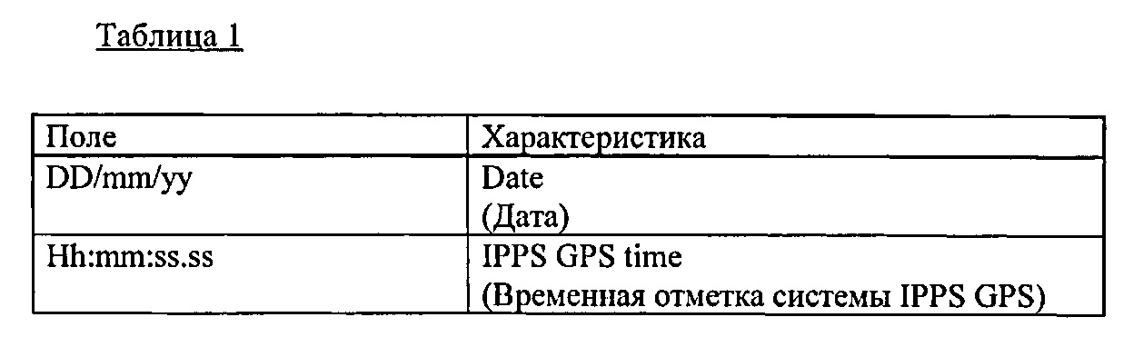
Система 100 по этому примеру осуществления способна работать в режиме «онлайн» (работа с сетью в режиме реального времени) или в режиме «оффлайн» (автономная работа без подключения к сети). В режиме «онлайн» система 100 принимает и магнитометрические данные с временной меткой GPS и навигационные данные в режиме реального времени. В режиме «оффлайн» система 100 в режиме реального времени принимает магнитометрические данные, но навигационные данные принимает только после того, как исследование завершено, например, с использованием съемного устройства, такого как флэш-накопитель с универсальной последовательной шиной (флэш-накопитель USB). Обычно навигационные данные включают в себя по меньшей мере абсолютные координаты дистанционно управляемого аппарата 120 (ROV) (и, следовательно, подводного блока 112 и любых дефектов / аномалий) с временными метками GPS, и данные километровых отметок (КР / kilometer post) - расстояние, пройденное дистанционно управляемым аппаратом 120 (ROV) вдоль трубопровода, начиная с момента движения. В этом примере осуществления изобретения навигационные данные предоставляются в кодах американского стандартного кода для обмена информацией (ASCII). Магнитометрические данные и навигационные данные сохраняются совместно в базе данных персонального компьютера PC 208 управляющего блока 102 (Фиг. 2) для последующей обработки.The
В таблице 1 представлены элементы навигационных данных для данного примера осуществления.Table 1 presents the navigation data elements for this embodiment.

В таблице 2 представлены элементы магнитометрических данных согласно примеру осуществления изобретения.Table 2 presents the elements of magnetometric data according to an example embodiment of the invention.

В качестве примера, компьютер PC 208 рассчитывает координаты дистанционно управляемого аппарата 120 (ROV) относительно надводного судна 110 для конкретной временной отметки на основе навигационных данных дистанционно управляемого аппарата 120 (ROV). Затем эти координаты соединяются с абсолютными координатами надводного судна ПО, принятыми со спутника GPS, для этой же временной отметки, чтобы определить абсолютные координаты дистанционно управляемого аппарата 120 (ROV). Если обнаружены аномалии в магнитометрических данных для этой же временной отметки, такая аномалия связывается с координатой, которая была определена. Согласно примеру осуществления изобретения, считывая и обрабатывая все данные, собранные в инспекционной проверке, определяются местоположения потенциальных дефектов, которые соответствуют аномалиям в магнитометрических данных.As an example, the
Кроме того, согласно примеру осуществления изобретения, система способна оценить степень опасности дефекта, путем расчета безопасного рабочего давления трубопровода, и путем расчета продолжительности безопасной работы трубопровода. Интегральный индекс F степени опасности дефекта, который принимает во внимание протяженность магнитной аномалии, амплитуду и конфигурацию распределения вектора интенсивности магнитного поля, превышающие фоновые значения, рассчитываются, согласно примеру осуществления изобретения, на основе следующей формулы:In addition, according to an example embodiment of the invention, the system is able to assess the degree of danger of a defect by calculating the safe working pressure of the pipeline, and by calculating the duration of safe operation of the pipeline. The integral index F of the degree of danger of the defect, which takes into account the extent of the magnetic anomaly, the amplitude and the distribution configuration of the magnetic field intensity vector in excess of the background values, are calculated, according to an example embodiment of the invention, based on the following formula:

где А означает корректирующий коэффициент, характеризующий влияние дефектов трубопровода на изменение магнитного поля, и обычно определяется после процедуры калибровки; Qaн, Qф (А/м) означают соответственно плотность распределения напряженности магнитного поля вдоль оси трубопровода в аномальной зоне и в "calm" фоновой зоны. Обычно плотность определяется на длине участка кривой. В данном изобретении кривая является геометрическим местом точек интенсивности магнитного поля в пространстве соответственно:where A means a correction factor characterizing the effect of pipeline defects on a change in the magnetic field, and is usually determined after the calibration procedure; Q an , Q f (A / m) mean respectively the distribution density of the magnetic field along the axis of the pipeline in the anomalous zone and in the "calm" background zone. Typically, the density is determined over the length of the curve. In this invention, the curve is a geometric locus of points of intensity of the magnetic field in space, respectively:

где dHx, dHy, dHz означают значения вектора изменения напряженности магнитного поля (А/м2) соответственно.where dH x , dH y , dH z mean the values of the vector of variation of the magnetic field strength (A / m 2 ), respectively.
В данном изобретении, Qaн и Qф рассчитывают путем интегрирования dQ по длине аномалии и фоновым зонам соответственно.In the present invention, Q an and Q f are calculated by integrating dQ over the length of the anomaly and background zones, respectively.
Рассчитанные значения индекса F сохраняют, например, в базе данных обнаруженных дефектов, а также в виде графиков распределения аномалий. Таблица 3 предоставляет ранжирование мест (то есть местоположений) с магнитными аномалиями на основе степени их опасности. На месте с первым рангом по опасности, ремонтно-восстановительные работы выполняются в первую очередь. На месте со вторым рангом по опасности планируются плановые ремонтно-восстановительные работы. На месте с третьим рангом по опасности работа трубопровода разрешается без ремонтно-восстановительных работ.The calculated values of the index F are stored, for example, in a database of detected defects, as well as in the form of graphs of the distribution of anomalies. Table 3 provides a ranking of places (i.e., locations) with magnetic anomalies based on their severity. On the spot with the first hazard rank, repair work is carried out first. Planned repair and restoration work is planned at a place with a second hazard rank. In a place with a third hazard rank, the operation of the pipeline is permitted without repair work.

Дополнительно, в данном примере осуществления изобретения безопасное давление для работы трубопровода Psafe рассчитывают на основе относительной степени опасности дефекта.Additionally, in this embodiment, the safe pressure for the operation of the P safe pipeline is calculated based on the relative severity of the defect.
Для секций с дефектами с первым рангом по опасности (т.е. 0≤F≤0,2),For sections with defects with a first hazard rank (i.e. 0≤F≤0,2),

Для секций с дефектами со вторым рангом по опасности (т.е. 0,2≤F≤For defective sections with a second hazard rank (i.e. 0.2≤F≤
0,55):0.55):

Для секций с дефектами с третьим рангом по опасности (т.е. F≥0,55):For sections with defects with a third hazard rank (i.e., F≥0.55):
![]()
![]()
где Рoper означает давление в трубопроводе на момент инспектирования, измеренное в мегапаскалях (МРа); Pdesign означает проектное давление в трубопроводе (в МРа); и Psafe означает безопасное рабочее давление в трубопроводе (в МРа).where P oper means the pressure in the pipeline at the time of inspection, measured in megapascals (MPa); P design means design pressure in the pipeline (in MPa); and P safe means safe working pressure in the pipeline (in MPa).
Если рассчитанное значение безопасного рабочего давления Psafe превышает проектное давление Pdesign, трубопровод предпочтительно работает при проектном давлении. Оценка технического состояния трубопровода может также выполняться на основе коэффициента безопасного давления «CSP», где:If the calculated value of the safe working pressure P safe exceeds the design pressure P design , the pipeline preferably works at the design pressure. The assessment of the technical condition of the pipeline can also be carried out on the basis of the safe pressure coefficient "CSP", where:

Согласно примеру осуществления изобретения, при CSP≥1, дефект определяется как критический и подлежащим первоочередному ремонту.According to an exemplary embodiment of the invention, with CSP≥1, a defect is defined as critical and needs to be repaired first.
Для кратковременной работы трубопровода максимально допустимое рабочее давление Рmax (известное также как МАОР), согласно примеру осуществления изобретения, рассчитывают:For short-term operation of the pipeline, the maximum allowable working pressure P max (also known as MAOP), according to an example embodiment of the invention, is calculated:
![]()
![]()
где τ означает коэффициент кратковременного увеличения давления, который определяется проектной организацией и, согласно примеру осуществления изобретения, может изменяться в диапазоне от 1,1 до 1,15.where τ means the coefficient of short-term pressure increase, which is determined by the design organization and, according to an example embodiment of the invention, can vary in the range from 1.1 to 1.15.
Согласно примеру осуществления изобретения, продолжительность безопасной работы трубопровода (т.е., безаварийной работы) - Tsafe рассчитывают из условия, что трубопровод работает при расчетном безопасном давлении, как описано выше с учетом уравнений (3)-(6). После выполнения ремонта всех обнаруженных дефектов продолжительность безопасной работы трубопровода устанавливают не более 90% от расчетного значения. Для каждого обнаруженного дефекта согласно примеру осуществления изобретения расчеты выполняют с использованием следующей формулы:According to an embodiment of the invention, the duration of safe operation of the pipeline (i.e., trouble-free operation) - T safe is calculated from the condition that the pipeline operates at the calculated safe pressure, as described above, taking into account equations (3) - (6). After performing repair of all detected defects, the duration of the safe operation of the pipeline is set to no more than 90% of the calculated value. For each detected defect according to an example embodiment of the invention, the calculations are performed using the following formula:
![]()
![]()
где Кр означает коэффициент, учитывающий давление в трубопроводе; KF означает коэффициент, учитывающий степень опасности дефекта; и Kt означает коэффициент, который принимает во внимание продолжительность работы трубопровода.where K p means a coefficient taking into account the pressure in the pipeline; K F means coefficient taking into account the degree of danger of the defect; and K t means a coefficient that takes into account the duration of the pipeline.
Например, если трубопровод работает при проектном давлении, то Кр=1, в ином случаее:For example, if the pipeline operates at design pressure, then K p = 1, otherwise:

Кроме того, ![]()
![]()
Kt учитывает влияние рабочих факторов, в частности, вероятность разрушения трубопровода в первые 3 года эксплуатации из-за строительно-монтажных дефектов и из-за коррозионного разрушения после 5-7 лет эксплуатации.K t takes into account the influence of working factors, in particular, the probability of pipeline destruction in the first 3 years of operation due to construction defects and due to corrosion damage after 5-7 years of operation.
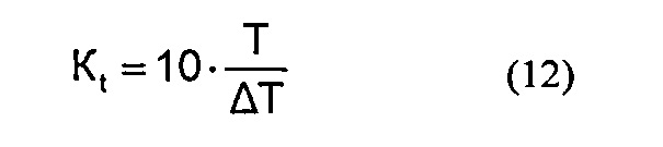
где Т означает нормативную продолжительность эксплуатации трубопровода (измеряемую в годах), a ΔT означает продолжительность работы трубопровода, начиная с момента ввода его в эксплуатацию (измеряется в годах).where T means the standard operating time of the pipeline (measured in years), and ΔT means the duration of the pipeline, starting from the moment it was put into operation (measured in years).
На Фиг. 6 показана блок-схема 600, иллюстрирующая способ инспектирования подводного трубопровода в соответствии с осуществлением изобретения. На шаге 602, дефект вдоль подводного трубопровода обнаруживают с использованием погружаемого под воду модуля МТМ (модуль, использующий способ магнитной томографии), расположенного рядом с подводным трубопроводом. На шаге 604, определяют местоположение погружаемого под воду модуля МТМ, определяя тем самым местоположение этого дефекта.In FIG. 6 is a
Согласно примеру осуществления изобретения, предлагаемые способ и система могут дать преимущественную возможность для трубопроводов, в которых нельзя использовать внутритрубную дефектоскопию с побережья. Даже для подводных трубопроводов, которые могут использовать внутритрубную дефектоскопию, необходимость предварительной подготовки трубопровода для инспектирования (то есть - очистка внутренней полости трубопровода, проверка геометрии перед прогоном диагностического модуля-дефектоскопа, размещение опорных точек, намагничивание металла трубопровода) преимущественно может быть уменьшена. Также не требуется дополнительное оборудование для запуска дефектоскопа / приема дефектоскопа. Таким образом, по сравнению с известными способами, такими как использование интеллектуального дефектоскопа, может быть уменьшена стоимость.According to an example embodiment of the invention, the proposed method and system can provide an advantageous opportunity for pipelines in which in-line flaw detection from the coast cannot be used. Even for subsea pipelines that can use in-line flaw detection, the need for preliminary preparation of the pipeline for inspection (i.e. cleaning the internal cavity of the pipeline, checking the geometry before running the diagnostic flaw detector module, locating reference points, magnetizing the metal of the pipeline) can mainly be reduced. Also, additional equipment is not required to run the flaw detector / flaw detector. Thus, in comparison with known methods, such as using an intelligent flaw detector, the cost can be reduced.
Дополнительно, согласно примеру осуществления изобретения, способ и система могут иметь высокую чувствительность, в связи с бесконтактной регистрацией магнитного поля трубопровода и фильтрацией значимого сигнала над помехой. Это означает, что дефекты металла, вызванные напряженно-деформированным состоянием, обычно не теряются во время инспектирования. Преимущественно, в настоящем изобретении регистрируется изменение магнитного поля целой дефектной секции, а не отдельного дефекта. То есть, согласно примеру осуществления изобретения, способ и система могут предоставить количественную оценку концентратора напряжений F для всех взаимосвязанных дефектов регистрируемой магнитной аномалии (или аномалии напряженно-деформированного состояния, получаемой из кластера).Additionally, according to an example embodiment of the invention, the method and system can have high sensitivity, in connection with the non-contact detection of the magnetic field of the pipeline and filtering a significant signal over the noise. This means that metal defects caused by a stress-strain state are usually not lost during inspection. Advantageously, in the present invention, a change in the magnetic field of an entire defective section, rather than a single defect, is detected. That is, according to an example embodiment of the invention, the method and system can provide a quantitative assessment of the stress concentrator F for all interconnected defects of the detected magnetic anomaly (or anomaly of the stress-strain state obtained from the cluster).
Кроме того, согласно примеру осуществления изобретения, способ и система могут иметь преимущественно единственный дефектоскоп для инспектирования трубопроводов разного размера, и дает возможность оценить степень опасности дефектов разного типа на основе унифицированного количественного индекса F значения концентратора напряжений. Предпочтительно, это дает возможность выполнить оценку факторов качества ремонта (EFR) для дефектов типа «потеря металла», и других типов, таких как: «трещино-подобные» дефекты, дефекты сварных швов, «нарушение сплошности», «изменения геометрии» и т.д. Поэтому, возможно выполнить расчеты ремонтопригодности для всех типов дефектов, а не только дефектов типа «потеря металла» (коррозия).In addition, according to an exemplary embodiment of the invention, the method and system can have a predominantly single flaw detector for inspecting pipelines of different sizes, and makes it possible to assess the degree of danger of defects of different types on the basis of a unified quantitative index F of the voltage concentrator value. Preferably, this makes it possible to evaluate repair quality factors (EFR) for defects such as “loss of metal” and other types, such as: “crack-like” defects, defects in welds, “discontinuity”, “geometry changes”, etc. .d. Therefore, it is possible to perform maintainability calculations for all types of defects, and not just defects such as “metal loss” (corrosion).
В данном изобретении способ и система могут быть реализованы с помощью вычислительной системы, схематически показанной на Фиг. 7. Она может быть реализована как программное обеспечение, такое как компьютерная программа, выполняющаяся в вычислительной системе 700, и выдача команд вычислительной системе 700, чтобы выполнять способ по настоящему изобретению.In the present invention, the method and system can be implemented using the computer system shown schematically in FIG. 7. It can be implemented as software, such as a computer program running on a
Вычислительная система 700 содержит вычислительный модуль 702 модули ввода, такие как клавиатура 704 и мышь 706 и множество устройств вывода, таких как дисплей 708 и принтер 710.
Вычислительный модуль соединен с вычислительной сетью 712 с помощью приемлемого приемопередатчика 714, чтобы получить доступ, например, к Интернету и другим сетевым системам, таким как локальная сеть (LAN), или глобальная сеть (WAN).The computing module is connected to the
Вычислительный модуль 702 в настоящем изобретении включает в себя процессор 718, оперативное запоминающее устройство (RAM) 720 и постоянное запоминающее устройство (ROM) 722. Вычислительный модуль 702 также включает в себя ряд входных / выходных (I/O) интерфейсов, например, I/O интерфейс 724 к дисплею 708, и I/O интерфейс 726 к клавиатуре 704.
Элементы вычислительного модуля 702 обычно обмениваются информацией через встроенную шину 728 способами, известными специалистам из уровня техники.Elements of the
Прикладные программы обычно поставляются пользователям вычислительной системы 700 в кодированном виде на средствах для хранения данных, таких как диски CD-ROM, или носителях флэш-памяти и считываются с использованием соответствующих дисководов для носителей данных устройства 730 для хранения данных. Прикладная программа считывается и управляется при ее использовании процессором 718. Промежуточное хранение данных программы может быть выполнено с использование оперативного запоминающего устройства (RAM) 720.Applications are typically provided to users of
Специалистам должно быть понятно, что в настоящем изобретении могут быть сделаны многочисленные изменения и/или модификации, по сравнению с показанными в конкретных примерах осуществления, без отхода от духа и объема изобретения. Поэтому настоящее изобретение должно рассматриваться без ограничений во всех аспектах, которые должны быть описаны.Professionals should be clear that in the present invention can be made numerous changes and / or modifications, compared with those shown in specific embodiments, without departing from the spirit and scope of the invention. Therefore, the present invention should be considered without limitation in all aspects that should be described.
Claims (24)
Priority Applications (1)
| Application Number | Priority Date | Filing Date | Title |
|---|---|---|---|
| US13/336,302 US8841901B2 (en) | 2011-07-29 | 2011-12-23 | System and method for inspecting a subsea pipeline |
Applications Claiming Priority (1)
| Application Number | Priority Date | Filing Date | Title |
|---|---|---|---|
| PCT/RU2011/000572 WO2013019136A1 (en) | 2011-07-29 | 2011-07-29 | System and method for inspecting a subsea pipeline |
Publications (2)
| Publication Number | Publication Date |
|---|---|
| RU2011152497A RU2011152497A (en) | 2015-09-10 |
| RU2635751C2 true RU2635751C2 (en) | 2017-11-15 |
Family
ID=47629508
Family Applications (1)
| Application Number | Title | Priority Date | Filing Date |
|---|---|---|---|
| RU2011152497A RU2635751C2 (en) | 2011-07-29 | 2011-07-29 | System and method for inspecting underwater pipelines |
Country Status (8)
| Country | Link |
|---|---|
| EP (1) | EP2737242B1 (en) |
| CN (1) | CN104160203B (en) |
| BR (1) | BR112014002108B1 (en) |
| CA (1) | CA2843394C (en) |
| MY (1) | MY167657A (en) |
| NO (1) | NO2737242T3 (en) |
| RU (1) | RU2635751C2 (en) |
| WO (1) | WO2013019136A1 (en) |
Cited By (1)
| Publication number | Priority date | Publication date | Assignee | Title |
|---|---|---|---|---|
| RU2721473C1 (en) * | 2019-05-24 | 2020-05-19 | Федеральное государственное автономное образовательное учреждение высшего образования "Национальный исследовательский Томский государственный университет" (ТГУ, НИ ТГУ) | Robot for diagnostics and repair of pipeline transport |
Families Citing this family (7)
| Publication number | Priority date | Publication date | Assignee | Title |
|---|---|---|---|---|
| GB201203717D0 (en) | 2012-03-02 | 2012-04-18 | Speir Hunter Ltd | Fault detection for pipelines |
| AU2015264529B2 (en) | 2014-05-18 | 2019-07-04 | The Charles Stark Draper Laboratory, Inc. | System and method of measuring defects in ferromagnetic materials |
| US9743370B2 (en) | 2015-04-28 | 2017-08-22 | The Charles Stark Draper Laboratory, Inc. | Wireless network for sensor array |
| EP3314247A4 (en) | 2015-06-29 | 2019-01-23 | The Charles Stark Draper Laboratory, Inc. | System and method for characterizing ferromagnetic material |
| CN106015944B (en) * | 2016-05-03 | 2018-10-26 | 深圳市发利构件机械技术服务有限公司 | Deep seafloor pipeline cruising inspection system and its working method |
| CN110531430A (en) * | 2019-08-29 | 2019-12-03 | 中国石油天然气集团公司 | Processing method, device and the electronic equipment of submarine pipeline magnetic survey data |
| CN115656445A (en) * | 2022-11-11 | 2023-01-31 | 江苏省特种设备安全监督检验研究院 | Test method for detecting typical defects of directly-buried jacket steam pipeline |
Citations (4)
| Publication number | Priority date | Publication date | Assignee | Title |
|---|---|---|---|---|
| RU2294482C1 (en) * | 2005-10-18 | 2007-02-27 | Талгат Галимзянович Сабирзянов | Mode of control and detection of defects in pipelines out of ferromagnetic materials |
| WO2009007670A1 (en) * | 2007-07-11 | 2009-01-15 | Flexlife Limited | Inspection method |
| RU2348857C2 (en) * | 2004-03-26 | 2009-03-10 | Энертаг | Method and device for determination of flaws situation located in submerged empty construction |
| RU88453U1 (en) * | 2009-07-30 | 2009-11-10 | Закрытое акционерное общество Научно-Производственный Центр "Молния" | INSTRUMENT COMPLEX FOR NON-CONTACT DIAGNOSTICS OF THE TECHNICAL CONDITION OF UNDERGROUND PIPELINES M-1 |
Family Cites Families (6)
| Publication number | Priority date | Publication date | Assignee | Title |
|---|---|---|---|---|
| CA1161115A (en) * | 1980-07-28 | 1984-01-24 | Hartley A. French | Pipeline inspection and maintenance method |
| JPH09127252A (en) * | 1995-10-26 | 1997-05-16 | Kokusai Denshin Denwa Co Ltd <Kdd> | Probing system for submarine cable |
| KR100649620B1 (en) * | 2005-08-22 | 2006-11-27 | 한국전력공사 | Underwater cable surveying system with a manned submarine |
| CN100462884C (en) * | 2006-11-02 | 2009-02-18 | 上海交通大学 | Crawling intelligent controller in submarine pipeline |
| FR2915555B1 (en) * | 2007-04-25 | 2009-07-31 | Enertag | METHOD FOR OPTIMIZING THE PRECISION OF LOCATING A DEVICE CIRCULATING IN A HOLLOW STRUCTURE |
| RU103616U1 (en) * | 2010-09-27 | 2011-04-20 | Российская Федерация, от имени которой выступает Министерство промышленности и торговли Российской Федерации (Минпромторг России) | DEVICE FOR DETERMINING THE LOCATION OF A PRODUCT LEAK FROM UNDERWATER PIPELINES |
-
2011
- 2011-07-29 CA CA2843394A patent/CA2843394C/en active Active
- 2011-07-29 BR BR112014002108-2A patent/BR112014002108B1/en active IP Right Grant
- 2011-07-29 CN CN201180073536.0A patent/CN104160203B/en active Active
- 2011-07-29 WO PCT/RU2011/000572 patent/WO2013019136A1/en active Application Filing
- 2011-07-29 EP EP11870499.8A patent/EP2737242B1/en active Active
- 2011-07-29 NO NO11870499A patent/NO2737242T3/no unknown
- 2011-07-29 RU RU2011152497A patent/RU2635751C2/en active
- 2011-07-29 MY MYPI2014000253A patent/MY167657A/en unknown
Patent Citations (4)
| Publication number | Priority date | Publication date | Assignee | Title |
|---|---|---|---|---|
| RU2348857C2 (en) * | 2004-03-26 | 2009-03-10 | Энертаг | Method and device for determination of flaws situation located in submerged empty construction |
| RU2294482C1 (en) * | 2005-10-18 | 2007-02-27 | Талгат Галимзянович Сабирзянов | Mode of control and detection of defects in pipelines out of ferromagnetic materials |
| WO2009007670A1 (en) * | 2007-07-11 | 2009-01-15 | Flexlife Limited | Inspection method |
| RU88453U1 (en) * | 2009-07-30 | 2009-11-10 | Закрытое акционерное общество Научно-Производственный Центр "Молния" | INSTRUMENT COMPLEX FOR NON-CONTACT DIAGNOSTICS OF THE TECHNICAL CONDITION OF UNDERGROUND PIPELINES M-1 |
Cited By (1)
| Publication number | Priority date | Publication date | Assignee | Title |
|---|---|---|---|---|
| RU2721473C1 (en) * | 2019-05-24 | 2020-05-19 | Федеральное государственное автономное образовательное учреждение высшего образования "Национальный исследовательский Томский государственный университет" (ТГУ, НИ ТГУ) | Robot for diagnostics and repair of pipeline transport |
Also Published As
| Publication number | Publication date |
|---|---|
| EP2737242A1 (en) | 2014-06-04 |
| CN104160203B (en) | 2017-10-10 |
| EP2737242A4 (en) | 2016-01-27 |
| CN104160203A (en) | 2014-11-19 |
| CA2843394A1 (en) | 2013-02-07 |
| MY167657A (en) | 2018-09-21 |
| CA2843394C (en) | 2018-08-21 |
| WO2013019136A1 (en) | 2013-02-07 |
| RU2011152497A (en) | 2015-09-10 |
| NO2737242T3 (en) | 2018-02-03 |
| BR112014002108B1 (en) | 2020-12-08 |
| BR112014002108A8 (en) | 2020-01-14 |
| EP2737242B1 (en) | 2017-09-06 |
| BR112014002108A2 (en) | 2017-02-21 |
Similar Documents
| Publication | Publication Date | Title |
|---|---|---|
| RU2635751C2 (en) | System and method for inspecting underwater pipelines | |
| US9581567B2 (en) | System and method for inspecting subsea vertical pipeline | |
| US9964519B2 (en) | Non-destructive system and method for detecting structural defects | |
| US8841901B2 (en) | System and method for inspecting a subsea pipeline | |
| US9176096B2 (en) | Apparatus and method for metallic constructions assessment | |
| CA2826139C (en) | Apparatus for the non-contact metallic constructions assessment | |
| JP5113340B2 (en) | Method and system for inspecting an object using ultrasonic scanning data | |
| US8447532B1 (en) | Metallic constructions integrity assessment and maintenance planning method | |
| US10330641B2 (en) | Metallic constructions monitoring and assessment in unstable zones of the earth's crust | |
| JP2006519369A (en) | Method and apparatus for scanning corrosion and surface defects | |
| US9746444B2 (en) | Autonomous pipeline inspection using magnetic tomography | |
| RU2697008C1 (en) | Method for in-pipe diagnostics of pipeline technical state | |
| Zhang et al. | A review of the integrity management of subsea production systems: Inspection and monitoring methods | |
| RU2526579C2 (en) | Testing of in-pipe inspection instrument at circular pipeline site | |
| Beller et al. | Combined quantitative in-line inspection of pipelines for metal loss and cracks | |
| Shitashima et al. | Strategies for detection and monitoring of CO2 leakage in sub-seabed CCS | |
| RU2739279C1 (en) | Universal flaw detector for control of technical state of walls of sleeves | |
| RU2715078C1 (en) | Method for determination of centers of developing underfilm corrosion of gas pipelines | |
| Wang et al. | Research on the error correction algorithm for caliper center offset in the offshore pipeline | |
| RU2279651C1 (en) | Method of prolonging safety service life of metal structures | |
| Hedayati et al. | Expert system development for acoustic analysis in concrete harbor NDT | |
| RU2631514C2 (en) | Oil-and-gas well casing failure assessment method | |
| Lagunova et al. | Evaluation of Metal Structures of a Mining Excavator Boom by Non-destructive Testing | |
| Grytten et al. | RISK BASED SUBSEA INSPECTION PLANNING AND INTEGRITY MANAGEMENT BY USE OF FIGS® SENSOR | |
| Dmitrievsky et al. | Monitoring technical state of pipelines in difficult conditions |