RU2628503C2 - Method and device for holes making in part using laser pulses - Google Patents
Method and device for holes making in part using laser pulses Download PDFInfo
- Publication number
- RU2628503C2 RU2628503C2 RU2014153930A RU2014153930A RU2628503C2 RU 2628503 C2 RU2628503 C2 RU 2628503C2 RU 2014153930 A RU2014153930 A RU 2014153930A RU 2014153930 A RU2014153930 A RU 2014153930A RU 2628503 C2 RU2628503 C2 RU 2628503C2
- Authority
- RU
- Russia
- Prior art keywords
- resonator
- holes
- temperature
- laser
- laser generator
- Prior art date
Links
Images
Classifications
-
- B—PERFORMING OPERATIONS; TRANSPORTING
- B23—MACHINE TOOLS; METAL-WORKING NOT OTHERWISE PROVIDED FOR
- B23K—SOLDERING OR UNSOLDERING; WELDING; CLADDING OR PLATING BY SOLDERING OR WELDING; CUTTING BY APPLYING HEAT LOCALLY, e.g. FLAME CUTTING; WORKING BY LASER BEAM
- B23K26/00—Working by laser beam, e.g. welding, cutting or boring
- B23K26/36—Removing material
- B23K26/38—Removing material by boring or cutting
-
- B—PERFORMING OPERATIONS; TRANSPORTING
- B23—MACHINE TOOLS; METAL-WORKING NOT OTHERWISE PROVIDED FOR
- B23K—SOLDERING OR UNSOLDERING; WELDING; CLADDING OR PLATING BY SOLDERING OR WELDING; CUTTING BY APPLYING HEAT LOCALLY, e.g. FLAME CUTTING; WORKING BY LASER BEAM
- B23K26/00—Working by laser beam, e.g. welding, cutting or boring
- B23K26/14—Working by laser beam, e.g. welding, cutting or boring using a fluid stream, e.g. a jet of gas, in conjunction with the laser beam; Nozzles therefor
- B23K26/1435—Working by laser beam, e.g. welding, cutting or boring using a fluid stream, e.g. a jet of gas, in conjunction with the laser beam; Nozzles therefor involving specially adapted flow-control means
-
- B—PERFORMING OPERATIONS; TRANSPORTING
- B23—MACHINE TOOLS; METAL-WORKING NOT OTHERWISE PROVIDED FOR
- B23K—SOLDERING OR UNSOLDERING; WELDING; CLADDING OR PLATING BY SOLDERING OR WELDING; CUTTING BY APPLYING HEAT LOCALLY, e.g. FLAME CUTTING; WORKING BY LASER BEAM
- B23K26/00—Working by laser beam, e.g. welding, cutting or boring
- B23K26/02—Positioning or observing the workpiece, e.g. with respect to the point of impact; Aligning, aiming or focusing the laser beam
- B23K26/06—Shaping the laser beam, e.g. by masks or multi-focusing
- B23K26/062—Shaping the laser beam, e.g. by masks or multi-focusing by direct control of the laser beam
- B23K26/0622—Shaping the laser beam, e.g. by masks or multi-focusing by direct control of the laser beam by shaping pulses
-
- B—PERFORMING OPERATIONS; TRANSPORTING
- B23—MACHINE TOOLS; METAL-WORKING NOT OTHERWISE PROVIDED FOR
- B23K—SOLDERING OR UNSOLDERING; WELDING; CLADDING OR PLATING BY SOLDERING OR WELDING; CUTTING BY APPLYING HEAT LOCALLY, e.g. FLAME CUTTING; WORKING BY LASER BEAM
- B23K26/00—Working by laser beam, e.g. welding, cutting or boring
- B23K26/36—Removing material
- B23K26/38—Removing material by boring or cutting
- B23K26/382—Removing material by boring or cutting by boring
- B23K26/389—Removing material by boring or cutting by boring of fluid openings, e.g. nozzles, jets
-
- H—ELECTRICITY
- H01—ELECTRIC ELEMENTS
- H01S—DEVICES USING THE PROCESS OF LIGHT AMPLIFICATION BY STIMULATED EMISSION OF RADIATION [LASER] TO AMPLIFY OR GENERATE LIGHT; DEVICES USING STIMULATED EMISSION OF ELECTROMAGNETIC RADIATION IN WAVE RANGES OTHER THAN OPTICAL
- H01S3/00—Lasers, i.e. devices using stimulated emission of electromagnetic radiation in the infrared, visible or ultraviolet wave range
- H01S3/09—Processes or apparatus for excitation, e.g. pumping
- H01S3/091—Processes or apparatus for excitation, e.g. pumping using optical pumping
- H01S3/0915—Processes or apparatus for excitation, e.g. pumping using optical pumping by incoherent light
- H01S3/092—Processes or apparatus for excitation, e.g. pumping using optical pumping by incoherent light of flash lamp
- H01S3/093—Processes or apparatus for excitation, e.g. pumping using optical pumping by incoherent light of flash lamp focusing or directing the excitation energy into the active medium
-
- H—ELECTRICITY
- H01—ELECTRIC ELEMENTS
- H01S—DEVICES USING THE PROCESS OF LIGHT AMPLIFICATION BY STIMULATED EMISSION OF RADIATION [LASER] TO AMPLIFY OR GENERATE LIGHT; DEVICES USING STIMULATED EMISSION OF ELECTROMAGNETIC RADIATION IN WAVE RANGES OTHER THAN OPTICAL
- H01S3/00—Lasers, i.e. devices using stimulated emission of electromagnetic radiation in the infrared, visible or ultraviolet wave range
- H01S3/10—Controlling the intensity, frequency, phase, polarisation or direction of the emitted radiation, e.g. switching, gating, modulating or demodulating
- H01S3/102—Controlling the intensity, frequency, phase, polarisation or direction of the emitted radiation, e.g. switching, gating, modulating or demodulating by controlling the active medium, e.g. by controlling the processes or apparatus for excitation
- H01S3/1028—Controlling the intensity, frequency, phase, polarisation or direction of the emitted radiation, e.g. switching, gating, modulating or demodulating by controlling the active medium, e.g. by controlling the processes or apparatus for excitation by controlling the temperature
-
- B—PERFORMING OPERATIONS; TRANSPORTING
- B23—MACHINE TOOLS; METAL-WORKING NOT OTHERWISE PROVIDED FOR
- B23K—SOLDERING OR UNSOLDERING; WELDING; CLADDING OR PLATING BY SOLDERING OR WELDING; CUTTING BY APPLYING HEAT LOCALLY, e.g. FLAME CUTTING; WORKING BY LASER BEAM
- B23K2101/00—Articles made by soldering, welding or cutting
- B23K2101/001—Turbines
-
- H—ELECTRICITY
- H01—ELECTRIC ELEMENTS
- H01S—DEVICES USING THE PROCESS OF LIGHT AMPLIFICATION BY STIMULATED EMISSION OF RADIATION [LASER] TO AMPLIFY OR GENERATE LIGHT; DEVICES USING STIMULATED EMISSION OF ELECTROMAGNETIC RADIATION IN WAVE RANGES OTHER THAN OPTICAL
- H01S3/00—Lasers, i.e. devices using stimulated emission of electromagnetic radiation in the infrared, visible or ultraviolet wave range
- H01S3/02—Constructional details
- H01S3/04—Arrangements for thermal management
- H01S3/0407—Liquid cooling, e.g. by water
-
- H—ELECTRICITY
- H01—ELECTRIC ELEMENTS
- H01S—DEVICES USING THE PROCESS OF LIGHT AMPLIFICATION BY STIMULATED EMISSION OF RADIATION [LASER] TO AMPLIFY OR GENERATE LIGHT; DEVICES USING STIMULATED EMISSION OF ELECTROMAGNETIC RADIATION IN WAVE RANGES OTHER THAN OPTICAL
- H01S3/00—Lasers, i.e. devices using stimulated emission of electromagnetic radiation in the infrared, visible or ultraviolet wave range
- H01S3/05—Construction or shape of optical resonators; Accommodation of active medium therein; Shape of active medium
- H01S3/06—Construction or shape of active medium
- H01S3/0602—Crystal lasers or glass lasers
- H01S3/061—Crystal lasers or glass lasers with elliptical or circular cross-section and elongated shape, e.g. rod
-
- H—ELECTRICITY
- H01—ELECTRIC ELEMENTS
- H01S—DEVICES USING THE PROCESS OF LIGHT AMPLIFICATION BY STIMULATED EMISSION OF RADIATION [LASER] TO AMPLIFY OR GENERATE LIGHT; DEVICES USING STIMULATED EMISSION OF ELECTROMAGNETIC RADIATION IN WAVE RANGES OTHER THAN OPTICAL
- H01S3/00—Lasers, i.e. devices using stimulated emission of electromagnetic radiation in the infrared, visible or ultraviolet wave range
- H01S3/14—Lasers, i.e. devices using stimulated emission of electromagnetic radiation in the infrared, visible or ultraviolet wave range characterised by the material used as the active medium
- H01S3/16—Solid materials
- H01S3/163—Solid materials characterised by a crystal matrix
- H01S3/164—Solid materials characterised by a crystal matrix garnet
- H01S3/1643—YAG
Landscapes
- Physics & Mathematics (AREA)
- Optics & Photonics (AREA)
- Engineering & Computer Science (AREA)
- Plasma & Fusion (AREA)
- Electromagnetism (AREA)
- Mechanical Engineering (AREA)
- Laser Beam Processing (AREA)
- Lasers (AREA)
Abstract
Description
Изобретение относится к выполнению отверстий в детали, в частности детали турбомашины, при помощи импульсного лазера.The invention relates to making holes in a part, in particular a turbomachine part, using a pulsed laser.
Во многих деталях турбомашины выполняют отверстия, предназначенные, например, для пропускания охлаждающих воздушных потоков. В частности, это относится к турбинным лопаткам и сопловым аппаратам, а также к стенкам камеры сгорания, причем эти стенки могут содержать несколько тысяч отверстий для охлаждения.In many details of the turbomachine, holes are made, for example, for transmitting cooling air flows. In particular, this applies to turbine blades and nozzle devices, as well as to the walls of the combustion chamber, and these walls may contain several thousand openings for cooling.
Для обеспечения эффективного охлаждения этих деталей и чтобы не сокращать срок их службы, выполненные отверстия должны иметь особую геометрию и не должны иметь микротрещин на своих внутренних стенках. Кроме того, технология, используемая для выполнения отверстий, должна как можно меньше влиять на состояние материала деталей.To ensure effective cooling of these parts and not to shorten their service life, the holes should have a special geometry and should not have microcracks on their inner walls. In addition, the technology used to make the holes should as little as possible affect the condition of the material of the parts.
Известны три разные технологии выполнения отверстий в детали турбомашины, предназначенные для образования отверстий охлаждения: выполнение отверстий режущим инструментом, выполнение отверстий EDM (Electrical Discharge Machining) и выполнение отверстий лазерными импульсами.Three different technologies are known for making holes in a turbomachine part for forming cooling holes: making holes with a cutting tool, making holes EDM (Electrical Discharge Machining), and making holes with laser pulses.
Выполнение отверстий при помощи режущего инструмента не подходит для получения отверстий небольшого диаметра (например, размером от 0,4 до 1,5 мм). Выполнение отверстий посредством EDM позволяет получать отверстия небольшого размера. Однако учитывая, что этот тип выполнения отверстий является относительно дорогим, его применяют для деталей, содержащих небольшое количество охлаждающих отверстий.Making holes with a cutting tool is not suitable for making holes of small diameter (for example, from 0.4 to 1.5 mm in size). Making holes with EDM allows you to get small holes. However, given that this type of hole design is relatively expensive, it is used for parts containing a small number of cooling holes.
Выполнение отверстий посредством лазерных импульсов (например, типа YAG) тоже позволяет выполнять отверстия небольшого размера. Однако известные лазерные устройства применяют только для выполнения небольшого числа последовательных отверстий, так как они не являются стабильными, и поскольку качество и уровень повторяемости геометрии отверстий снижаются по истечении некоторого времени использования устройств. Например, было отмечено, что когда лазерное устройство используют для выполнения отверстий круглого сечения, после определенного времени использования этого устройства сечение выполняемых отверстий становится эллиптическим. Следовательно, это устройство используют в течение относительно коротких промежутков времени и оставляют выключенным в течение относительно длительного времени между двумя последовательными использованиями.Making holes using laser pulses (such as YAG type) also allows you to make small holes. However, known laser devices are used only to make a small number of consecutive holes, since they are not stable, and since the quality and repeatability of the geometry of the holes decrease after some time of use of the devices. For example, it was noted that when a laser device is used to make holes of circular cross section, after a certain time of using this device, the cross section of the holes made becomes elliptical. Therefore, this device is used for relatively short periods of time and left off for a relatively long time between two consecutive uses.
Как правило, импульсный лазер содержит резонатор, внутри которого установлен твердый стержень для генерирования лазерных импульсов. Обычно этот стержень имеет удлиненную форму и образует усиливающую среду, в которую излучаются фотоны по меньшей мере от одной лампы-вспышки, находящейся в резонаторе. На продольных концах стержня расположены два зеркала, одно из которых является по меньшей мер, частично отражающим. Кроме того, резонатор лазера содержит температурный датчик, связанный со средствами детектирования, предназначенными для оповещения оператора, когда температура резонатора достигает определенного порога. Чтобы избежать достижения этого порога резонатором, во время работы его охлаждают.Typically, a pulsed laser contains a resonator, inside of which is mounted a solid rod for generating laser pulses. Usually this rod has an elongated shape and forms an amplifying medium into which photons are emitted from at least one flash lamp located in the cavity. At the longitudinal ends of the rod are two mirrors, one of which is at least partially reflective. In addition, the laser resonator contains a temperature sensor associated with the detection means, designed to alert the operator when the temperature of the resonator reaches a certain threshold. To avoid reaching this threshold by the resonator, it is cooled during operation.
В известных решениях при управлении или программировании лазерного генератора температуру лазерного резонатора не учитывают. Вышеупомянутый температурный порог резонатора является постоянным при любых характеристиках детали или выполняемых отверстий и его определяют, просто чтобы гарантировать оптимальный срок службы лазерного генератора.In known solutions, when controlling or programming a laser generator, the temperature of the laser resonator is not taken into account. The aforementioned temperature threshold of the resonator is constant for any characteristics of the part or holes made and is determined simply to guarantee the optimal life of the laser generator.
Изобретение призвано предложить простое, эффективное и экономичное решение вышеупомянутой проблемы, связанной с использованием импульсного лазера для выполнения отверстий в детали.The invention is intended to provide a simple, effective and economical solution to the aforementioned problem associated with the use of a pulsed laser to make holes in the part.
Изобретением предложен способ выполнения отверстий в детали, в частности турбомашины, при помощи импульсного лазерного генератора, содержащего резонатор (с управляемой температурой), в котором установлен твердый стержень, обеспечивающий генерирование лазерного пучка.The invention provides a method for making holes in a part, in particular a turbomachine, using a pulsed laser generator containing a resonator (with temperature control), in which a solid rod is installed, which ensures the generation of a laser beam.
В связи с этим объектом изобретения является способ выполнения отверстий в детали, в частности турбомашины, при помощи импульсного лазерного генератора, содержащего резонатор, в котором установлен твердый стержень для генерирования лазерных импульсов, при этом способ содержит этап, на котором определяют значения нескольких рабочих параметров лазерного генератора для выполнения отверстий заранее определенного диаметра в детали, отличающийся тем, что определяют заданное значение температуры резонатора лазерного генератора в зависимости от характеристик выполняемых отверстий и/или от материала детали, в которой выполняют отверстия, и регулируют температуру резонатора по этому заданному значению во время выполнения отверстий.In this regard, an object of the invention is a method of making holes in a part, in particular a turbomachine, using a pulsed laser generator containing a resonator in which a solid rod for generating laser pulses is mounted, the method comprising the step of determining the values of several laser operating parameters generator for making holes of a predetermined diameter in the part, characterized in that they determine the set temperature of the resonator of the laser generator depending depending on the characteristics of the holes being made and / or on the material of the part in which the holes are made, and the resonator temperature is adjusted to this predetermined value during the making of the holes.
Авторы изобретения установили, что температура резонатора лазерного генератора, в котором находится стержень, влияет на мощность, выдаваемую лазерным генератором, и, следовательно, на геометрию выполняемых отверстий, а также на появление микротрещин на внутренних стенках этих отверстий.The inventors found that the temperature of the resonator of the laser generator in which the rod is located affects the power output by the laser generator, and therefore the geometry of the holes made, as well as the appearance of microcracks on the inner walls of these holes.
Рабочими параметрами лазера являются, например, частота повторения импульсов (F), число импульсов, продолжительность импульса (Тр) и/или максимальная мощность лазерного генератора в процентах (Н%). Этот последний параметр Н% является заданным значением, которое позволяет лазерному генератору работать на части своей максимальной мощности или на полной мощности (Н%=100), например, за счет изменения тока его ламп-вспышек. Предпочтительно параметр Н% выбирают достаточно высоким (по меньшей мере, превышающим 25%) для обеспечения стабильности резонатора и мощности лазерного пучка.The laser operating parameters are, for example, pulse repetition rate (F), number of pulses, pulse duration (Tr) and / or maximum power of the laser generator in percent (N%). This last parameter H% is a given value, which allows the laser generator to work at part of its maximum power or at full power (H% = 100), for example, by changing the current of its flash lamps. Preferably, the H% parameter is selected high enough (at least greater than 25%) to ensure the stability of the resonator and the power of the laser beam.
Согласно изобретению, к параметрам, учитываемым при управлении, добавляют заранее определенную температуру резонатора и ее поддерживают по существу постоянной во время выполнения отверстий.According to the invention, a predetermined resonator temperature is added to the parameters taken into account during control and it is kept essentially constant during the making of holes.
Предпочтительно способ содержит этап, на котором определяют заданное значение температуры резонатора, при которой лазерный генератор является настроенным и выдает максимальную энергию при заранее определенных рабочих параметрах. Таким образом, выполнение отверстий производят при температуре резонатора, обеспечивающей настройку лазера. Эта температура должна быть гарантирована до ±3°С. Обтюратор лазерного пучка может быть управляемым только при соблюдении заданного значения температуры. При фиксированных параметрах способа изменение температуры резонатора (за пределами вышеупомянутого диапазона) может привести к «рассогласованию» лазерного генератора.Preferably, the method comprises the step of determining a predetermined value of the resonator temperature at which the laser generator is tuned and generates maximum energy at predetermined operating parameters. Thus, the holes are produced at a cavity temperature that provides laser tuning. This temperature must be guaranteed up to ± 3 ° C. The laser beam obturator can be controlled only if the set temperature value is observed. With fixed method parameters, a change in the temperature of the resonator (outside the aforementioned range) can lead to a “mismatch” of the laser generator.
Температуру резонатора генератора регулируют вокруг заданного значения во время работы лазера, что обеспечивает хорошую повторяемость и оптимальное качество отверстий. Лазерный генератор можно использовать в течение более длительных промежутков времени, чем в известных решениях, и его выключают, только если становится трудно или невозможно поддерживать температуру резонатора вокруг заданного значения (хотя этот риск является ничтожным, если применяют средства охлаждения резонатора).The temperature of the resonator of the generator is controlled around a predetermined value during the operation of the laser, which ensures good repeatability and optimal quality of the holes. The laser generator can be used for longer periods of time than in the known solutions, and it is turned off only if it becomes difficult or impossible to maintain the temperature of the resonator around a predetermined value (although this risk is negligible if resonator cooling means are used).
Изобретение отличается от известных решений, в частности, тем, что температура резонатора генератора является регулируемым рабочим параметром, который контролируют и регулируют для оптимизации характеристик отверстий.The invention differs from the known solutions, in particular in that the temperature of the resonator of the generator is an adjustable operating parameter that is monitored and adjusted to optimize the characteristics of the holes.
Регулирование этой температуры состоит в ее поддержании в значении, максимально близком к заданному (которое зависит, в частности, от характеристик детали, таких как ее материал, и которое может, таким образом, меняться от одной операции выполнения отверстий к другой), что отличается от известных решений, в которых резонатор охлаждают, чтобы избегать превышения максимальной рабочей температуры, причем эта рабочая температура может принимать любое значение ниже этого максимального значения, и охлаждение резонатора не меняют, пока не будет достигнуто это максимальное значение. В известных решениях лазерный генератор выключают, только когда температура его резонатора достигает этого максимального значения.The regulation of this temperature consists in maintaining it at a value as close as possible to a predetermined one (which depends, in particular, on the characteristics of the part, such as its material, and which may thus vary from one operation of making holes to another), which differs from known solutions in which the resonator is cooled in order to avoid exceeding the maximum working temperature, and this working temperature can take any value below this maximum value, and the cooling of the resonator is not changed until this maximum value is reached. In known solutions, the laser generator is turned off only when the temperature of its resonator reaches this maximum value.
Таким образом, целью изобретения является применение автоматического регулирования температуры лазерного резонатора, чтобы оптимизировать геометрию и характеристики выполняемых отверстий и обеспечивать более длительное время использования лазерного генератора при сохранении результатов этой оптимизации.Thus, the aim of the invention is the use of automatic temperature control of the laser resonator in order to optimize the geometry and characteristics of the holes and provide a longer time for using the laser generator while maintaining the results of this optimization.
Для выполнения отверстий лазерный генератор используют в настроенном режиме, то есть с оптимизацией параметров способа (Тр, F, Н%), чтобы получать максимум энергии на выходе лазерного генератора. Следствием изменения температуры резонатора лазерного генератора будет «рассогласование» лазера.To make holes, the laser generator is used in the configured mode, that is, with optimization of the method parameters (Tp, F, H%), in order to get the maximum energy at the output of the laser generator. The result of a change in the temperature of the resonator of the laser generator will be a "mismatch" of the laser.
Кроме того, авторы изобретения установили, что на геометрию отверстий можно влиять посредством изменения температуры резонатора.In addition, the inventors have found that the geometry of the holes can be influenced by changing the temperature of the resonator.
Температуру резонатора можно регулировать до ±3°С вокруг заданного значения. Заданное значение температуры составляет, например, от 25 до 40°С. Предпочтительно заданное значение определяют таким образом, чтобы отверстия были сквозными и имели круглое сечение.The resonator temperature can be adjusted up to ± 3 ° C around the set value. The setpoint temperature is, for example, from 25 to 40 ° C. Preferably, the predetermined value is determined so that the holes are through and have a circular cross section.
Температуру лазерного резонатора можно регулировать при помощи системы охлаждения резонатора за счет циркуляции охлаждающей текучей среды вблизи или внутри резонатора. Охлаждение резонатора можно оптимизировать, например, посредством изменения расхода и температуры охлаждающей текучей среды.The temperature of the laser cavity can be controlled using the cavity cooling system by circulating the cooling fluid near or inside the cavity. Resonator cooling can be optimized, for example, by varying the flow rate and temperature of the cooling fluid.
Деталью, в которой выполняют отверстия, может быть лопатка или сопловой аппарат турбины или стенка камеры сгорания турбомашины.The part in which the holes are made may be a turbine blade or nozzle apparatus or a wall of a combustion chamber of a turbomachine.
Лазером может быть, например, лазер типа YAG или импульсный лазер любого другого типа, в котором можно регулировать температуру лазерного резонатора.The laser may be, for example, a YAG type laser or any other type of pulsed laser in which the temperature of the laser cavity can be adjusted.
Объектом настоящего изобретения является также устройство для выполнения отверстий в детали, в частности турбомашины, при помощи импульсного лазерного генератора, содержащего резонатор, в котором установлен твердый стержень для генерирования лазерных импульсов, систему охлаждения резонатора за счет циркуляции охлаждающей текучей среды вокруг резонатора и средства управления рабочими параметрами лазера, отличающееся тем, что содержит средства автоматического регулирования температуры резонатора по заданному значению, зависящему от характеристик выполняемых отверстий, посредством изменения расхода и температуры охлаждающей текучей среды.The object of the present invention is also a device for making holes in a part, in particular a turbomachine, using a pulsed laser generator containing a resonator in which a solid rod for generating laser pulses is mounted, a resonator cooling system due to the circulation of the cooling fluid around the resonator and means for controlling workers laser parameters, characterized in that it contains means for automatically controlling the temperature of the resonator at a given value, depending on t of the characteristics of the holes made by changing the flow rate and temperature of the cooling fluid.
Изобретение и его другие детали, преимущества и отличительные признаки будут более очевидны из нижеследующего описания, представленного в качестве не ограничительного примера со ссылками на прилагаемые чертежи, на которых:The invention and its other details, advantages and features will be more apparent from the following description, presented by way of non-limiting example with reference to the accompanying drawings, in which:
Фиг. 1 - частичный схематичный вид в перспективе импульсного лазера.FIG. 1 is a partial schematic perspective view of a pulsed laser.
Фиг. 2 - частичный схематичный вид в разрезе детали и лазерного пучка для выполнения отверстий в этой детали.FIG. 2 is a partial schematic sectional view of a part and a laser beam for making holes in this part.
Фиг. 3 - блок-схема этапов заявленного способа выполнения отверстий в детали посредством лазерных импульсов.FIG. 3 is a flowchart of the claimed method for making holes in a part by means of laser pulses.
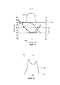
Фиг. 4 - график, показывающий изменение диаметра выполняемых отверстий и энергии лазерного пучка в зависимости от температуры лазерного резонатора, в котором установлен стержень, генерирующий лазерные импульсы.FIG. 4 is a graph showing the change in the diameter of the holes and the energy of the laser beam depending on the temperature of the laser resonator in which the rod generating the laser pulses is mounted.
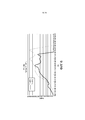
Фиг. 5 - график, показывающий изменение средней мощности лазерного пучка в зависимости от процента максимальной мощности лазерного генератора.FIG. 5 is a graph showing a change in the average power of the laser beam as a function of the percentage of maximum power of the laser generator.
Фиг. 6 - график, аналогичный графику на фиг. 5 и показывающий влияние температуры резонатора на среднюю мощность лазерного пучка.FIG. 6 is a graph similar to that of FIG. 5 and showing the effect of the resonator temperature on the average power of the laser beam.
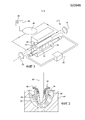
Рассмотрим сначала фиг. 1, где представлена часть импульсного лазерного генератора 10, например, типа YAG, причем этот генератор 10 содержит резонатор 12, внутри которого установлены твердый стержень 14 и лампы-вспышки 16 возбуждения твердого стержня.First, consider FIG. 1, where a part of a
Твердый стержень 14 имеет удлиненную цилиндрическую форму и проходит параллельно продольной оси резонатора 12, который в представленном примере тоже имеет удлиненную цилиндрическую форму. Стержень 12 является, например, кристаллом. На каждом из продольных концов стержня расположено зеркало 18, 20, причем одно 20 из этих зеркал является частично отражающим зеркалом.The
Лампы-вспышки 16 установлены, например, в количестве двух (на фиг. 1 показана только одна), при этом каждая лампа-вспышка соединена с электрическим источником 22 и выполнена с возможностью излучения фотонов в резонатор. В данном случае лампы 16 имеют удлиненную форму. Они расположены параллельно продольной оси резонатора, например, с двух сторон от стержня.Flash
Классически лазерное устройство выполнения отверстий посредством импульсов содержит лазерный генератор 10 вышеупомянутого типа, систему охлаждения резонатора 12 и средства управления рабочими параметрами лазерного генератора.Classically, a laser device for making holes by pulses comprises a
Лазерный резонатор 12 охлаждают посредством циркуляции охлаждающей текучей среды внутри резонатора, при этом стержень 14 и лампы-вспышки 16 погружены в эту текучую среду. Лазерный генератор 10 содержит теплообменник 24, соединенный со средствами циркуляции охлаждающей текучей среды в резонаторе и с резервуаром 26 охлаждающей текучей среды.The
Кроме того, лазерный генератор 10 содержит температурные датчики 28, например, типа термопар, которые установлены в резонаторе 12 и в резервуаре 26 охлаждающей текучей среды.In addition, the
Специалисту хорошо известна работа импульсного лазерного генератора 10 описанного выше типа.The specialist is well known for the operation of a
На фиг. 2 представлен вид в разрезе детали во время выполнения отверстий посредством лазерных импульсов, например при помощи описанного выше лазерного генератора 10. Позицией 40 обозначен пучок, излучаемый генератором, причем этот пучок направлен по существу перпендикулярно к поверхности детали 42, в которой выполняют отверстия. Пучок 40 состоит из множества последовательных импульсов, которые вызывают плавление материала детали (зона плавления 44), причем этот расплавленный материал частично испаряется (позиция 46) и частично выталкивается за пределы зоны плавления (позиция 48), остальная часть материала (позиция 50) остается на внутренних стенках отверстия во время выполнения. Периферическая зона 52, расположенная вокруг выполняемого отверстия, подвергается относительно большим термическим воздействиям. Эта зона 52, называемая зоной термического воздействия (ZAT), является местом образования микротрещин 54 во время выполнения отверстий.In FIG. 2 is a sectional view of the part during the making of holes by means of laser pulses, for example by means of the
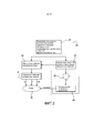
На фиг. 3 представлена блок-схема этапов заявленного способа 60 выполнения отверстий посредством лазерных импульсов.In FIG. 3 is a flowchart of the claimed
На первом этапе 62 способа определяют характеристики детали, в которой выполняют отверстия, а также характеристики отверстий, выполняемых в этой детали. Характеристиками детали являются, в частности, ее материал (например, сплав на основе никеля или кобальта) и толщина стенки детали, в которой выполняют отверстие, (как правило, от 0,8 до 15 мм). Они могут включать в себя различные другие данные, такие как форма и размеры детали, присутствие другой стенки вблизи детали, которую не должно затрагивать выполнение отверстий, присутствие покрытия (такого как теплоизоляционное покрытие) на детали, в которой выполняют отверстия, и т.д.At the
Характеристиками выполняемых отверстий являются, в частности, форма или геометрия этих отверстий, их размеры, угол между продольной осью каждого отверстия и нормалью к поверхности детали, глубина отверстий и т.д. Как правило, эти отверстия имеют общую цилиндрическую форму, то есть имеют круглое сечение, диаметр которого составляет, например, от 0,4 до 1,5 мм. Угол между осью каждого отверстия и нормалью к поверхности детали, как правило, составляет от 0 до 70°. Глубина отверстий равна толщине стенки, в которой выполняют отверстие, если отверстия проходят через эту стенку насквозь (то есть являются сквозными).The characteristics of the holes are, in particular, the shape or geometry of these holes, their dimensions, the angle between the longitudinal axis of each hole and the normal to the surface of the part, the depth of the holes, etc. Typically, these holes have a common cylindrical shape, that is, they have a circular cross section, the diameter of which is, for example, from 0.4 to 1.5 mm. The angle between the axis of each hole and the normal to the surface of the part, as a rule, is from 0 to 70 °. The depth of the holes is equal to the thickness of the wall in which the hole is made if the holes pass through this wall through (that is, they are through).
По меньшей мере, некоторые из вышеупомянутых характеристик используют для определения заданного значения температуры резонатора 12 лазерного генератора (этап 64). Например, это относится к геометрии выполняемых отверстий и к материалу детали. Температуру лазерного резонатора можно определять на основании этих характеристик при помощи графика, показанного на фиг. 4.At least some of the above characteristics are used to determine the temperature setpoint of the laser oscillator cavity 12 (step 64). For example, this applies to the geometry of the holes and to the material of the part. The temperature of the laser cavity can be determined based on these characteristics using the graph shown in FIG. four.
График на фиг. 4 показывает (для данных рабочих параметров лазерного генератора, таких как Тр, F и Н%, которые будут описаны ниже) изменение энергии посредством лазерного импульса (на оси ординат справа) и диаметра D отверстий (на оси ординат слева) в зависимости от температуры резонатора 12 (Т). Отмечается, что кривая 66 Е = f(T) имеет максимум Emax при температуре настройки (Тасс) резонатора, то есть при температуре резонатора, для которой настроен лазерный генератор, как было указано выше.The graph in FIG. 4 shows (for given operating parameters of the laser generator, such as Tp, F, and H%, which will be described below) the energy change by means of a laser pulse (on the ordinate axis on the right) and diameter D of the holes (on the ordinate axis on the left) depending on the resonator temperature 12 (T). It is noted that the curve 66 E = f (T) has a maximum Emax at the tuning temperature (Tass) of the resonator, that is, at the temperature of the resonator for which the laser generator is tuned, as indicated above.
В зависимости от материала, от необходимого диаметра отверстия, от его глубины и от его морфологии (цилиндрическое, эллиптическое сечение…) необходимо произвести идентификацию значений параметров Тр, F, Н% и температуры Т резонатора, позволяющих соблюдать эти спецификации.Depending on the material, on the required diameter of the hole, on its depth and on its morphology (cylindrical, elliptical section ...), it is necessary to identify the values of the parameters Tp, F, H% and the temperature T of the resonator, which allow observing these specifications.
В представленном примере параметрами при настройке лазерного генератора являются Тр=1 мс, F=35 Гц, Н=86% и Т=25°С.In the presented example, the parameters when setting up the laser generator are Tr = 1 ms, F = 35 Hz, H = 86% and T = 25 ° C.
График этого типа можно предварительно построить для каждого материала деталей, в которых можно выполнять отверстия посредством лазерного импульса в рамках заявленного способа. В случае когда одна и та же деталь может быть выполнена из металлического сплава на основе кобальта и из металлического сплава на основе никеля, необходимо строить график этого типа для каждого из этих сплавов.A graph of this type can be preliminarily constructed for each material of parts in which it is possible to make holes by means of a laser pulse in the framework of the claimed method. In the case when the same part can be made of a cobalt-based metal alloy and a nickel-based metal alloy, it is necessary to plot this type for each of these alloys.
Эта оптимальная температура представляет собой заданное значение, вокруг которого будут регулировать температуру резонатора во время выполнения отверстий (этап 80) для обеспечения вышеуказанных характеристик отверстий (геометрия, диаметр и т.д.). Таким образом, происходит автоматическое регулирование температуры лазерного резонатора.This optimum temperature is a predetermined value around which the resonator temperature will be adjusted during the making of holes (step 80) to ensure the above characteristics of the holes (geometry, diameter, etc.). Thus, the temperature of the laser resonator is automatically controlled.
В частности, регулирование температуры резонатора 12 лазера можно осуществлять следующим образом. Заявленное устройство для выполнения отверстий, кроме классических известных средств (лазерный генератор 10, средства управления и т.д.), содержит средства регулирования температуры лазерного резонатора. Эти средства автоматического регулирования содержат компаратор 88, который получает на входе измеренную температуру резонатора и заданное значение этой температуры и который определяет, являются ли эти значения достаточно близкими (таким образом, чтобы их разность была меньше или равна интервалу погрешности, например, ±1°). В случае когда температура резонатора оказывается слишком высокой по сравнению с заданным значением, в средства управления расходом и/или температурой охлаждающей текучей среды поступает выходной сигнал компаратора для увеличения охлаждения резонатора и понижения его температуры. В случае когда температура резонатора оказывается слишком низкой по сравнению с заданным значением, компаратор подает команду на уменьшение охлаждения резонатора, чтобы повысить его температуру. Это регулирование температуры резонатора происходит в течение всего времени выполнения отверстий, и компаратор 88 может осуществлять вышеупомянутые сравнения через равномерные интервалы, например, каждую секунду.In particular, the temperature control of the
Способ содержит также этапы 82, 84, на которых определяют рабочие параметры лазерного генератора при заданном значении (Т1) температуры лазерного резонатора, затем управляют этими параметрами во время выполнения отверстий.The method also includes
Рабочими параметрами лазерного генератора являются, например, частота повторения импульсов (F), число импульсов, продолжительность одного импульса (Тр), процент максимальной мощности лазерного генератора (Н%).The operating parameters of the laser generator are, for example, the pulse repetition rate (F), the number of pulses, the duration of one pulse (Tr), the percentage of the maximum power of the laser generator (N%).
График на фиг. 5 показывает изменение средней мощности (Pm) лазерного пучка в зависимости от процента максимальной мощности лазерного генератора (Н%). Отмечается, что кривая 86 имеет два пика 88, разделенных горизонтальным участком 90. Этот горизонтальный участок показывает, что при данном диапазоне значений Н% мощность Pm остается относительно постоянной. Этот тип графика можно строить для разных материалов и толщин, и он позволяет определить диапазон значений Н%, при котором средняя мощность лазерного пучка по существу является постоянной. График, показанный на фиг. 5, строят для данной продолжительности импульса (Тр) и для данной частоты импульсов (F).The graph in FIG. 5 shows the change in average power (Pm) of the laser beam as a function of the percentage of maximum laser power (N%). It is noted that
График на фиг. 6 является аналогичным графику на фиг. 5 и показывает изменение средней мощности (Pm) лазерного пучка в зависимости от процента максимальной мощности лазерного генератора (Н%) для двух разных температур резонатора (25 и 30°С). В представленном примере параметры Тр и F равны соответственно 2 мс и 35 Гц. Для данного заданного параметра Н% отмечается, что средняя мощность Pm меняется в зависимости от температуры резонатора. Для Н%=50 средняя мощность лазерного пучка равна 95 Вт при температуре резонатора 25°С и 120 Вт при температуре резонатора 30°С. Таким образом, этот график показывает влияние температуры резонатора на среднюю мощность и, следовательно, на энергию лазерного пучка, даже если другие рабочие параметры (Тр, F, Н%) лазерного генератора сохраняются постоянными.The graph in FIG. 6 is similar to the graph in FIG. 5 and shows the change in the average power (Pm) of the laser beam as a function of the percentage of the maximum power of the laser generator (N%) for two different cavity temperatures (25 and 30 ° C). In the presented example, the parameters Tr and F are equal to 2 ms and 35 Hz, respectively. For this given parameter H%, it is noted that the average power Pm varies depending on the temperature of the resonator. For H% = 50, the average laser beam power is 95 W at a resonator temperature of 25 ° C and 120 W at a resonator temperature of 30 ° C. Thus, this graph shows the effect of the resonator temperature on the average power and, therefore, on the energy of the laser beam, even if the other operating parameters (Tp, F, H%) of the laser generator are kept constant.
Лазерный генератор 90 предназначен для управления посредством контроля вышеупомянутых параметров (Tp, F, H% и т.д.), а также посредством регулирования температуры резонатора, как было указано выше, во время операции выполнения отверстий.The
Claims (10)
Applications Claiming Priority (3)
| Application Number | Priority Date | Filing Date | Title |
|---|---|---|---|
| FR1255128A FR2991214B1 (en) | 2012-06-01 | 2012-06-01 | METHOD FOR DRILLING A PIECE BY LASER PULSES |
| FR1255128 | 2012-06-01 | ||
| PCT/FR2013/051214 WO2013178950A1 (en) | 2012-06-01 | 2013-05-30 | Method and device for drilling a workpiece with laser pulses |
Publications (2)
| Publication Number | Publication Date |
|---|---|
| RU2014153930A RU2014153930A (en) | 2016-07-27 |
| RU2628503C2 true RU2628503C2 (en) | 2017-08-17 |
Family
ID=46963817
Family Applications (1)
| Application Number | Title | Priority Date | Filing Date |
|---|---|---|---|
| RU2014153930A RU2628503C2 (en) | 2012-06-01 | 2013-05-30 | Method and device for holes making in part using laser pulses |
Country Status (8)
| Country | Link |
|---|---|
| US (1) | US9713855B2 (en) |
| EP (1) | EP2855079B1 (en) |
| CN (1) | CN104379300B (en) |
| BR (1) | BR112014029934B1 (en) |
| CA (1) | CA2874565C (en) |
| FR (1) | FR2991214B1 (en) |
| RU (1) | RU2628503C2 (en) |
| WO (1) | WO2013178950A1 (en) |
Families Citing this family (13)
| Publication number | Priority date | Publication date | Assignee | Title |
|---|---|---|---|---|
| EP2754524B1 (en) | 2013-01-15 | 2015-11-25 | Corning Laser Technologies GmbH | Method of and apparatus for laser based processing of flat substrates being wafer or glass element using a laser beam line |
| EP2781296B1 (en) | 2013-03-21 | 2020-10-21 | Corning Laser Technologies GmbH | Device and method for cutting out contours from flat substrates using a laser |
| US10293436B2 (en) | 2013-12-17 | 2019-05-21 | Corning Incorporated | Method for rapid laser drilling of holes in glass and products made therefrom |
| US11556039B2 (en) | 2013-12-17 | 2023-01-17 | Corning Incorporated | Electrochromic coated glass articles and methods for laser processing the same |
| US10442719B2 (en) | 2013-12-17 | 2019-10-15 | Corning Incorporated | Edge chamfering methods |
| WO2015113302A1 (en) * | 2014-01-30 | 2015-08-06 | 西门子公司 | Simulation system and method for laser drilling process |
| TWI730945B (en) | 2014-07-08 | 2021-06-21 | 美商康寧公司 | Methods and apparatuses for laser processing materials |
| KR20170028943A (en) | 2014-07-14 | 2017-03-14 | 코닝 인코포레이티드 | System for and method of processing transparent materials using laser beam focal lines adjustable in length and diameter |
| US11773004B2 (en) | 2015-03-24 | 2023-10-03 | Corning Incorporated | Laser cutting and processing of display glass compositions |
| CN107661980B (en) * | 2016-07-29 | 2020-02-21 | 上海微电子装备(集团)股份有限公司 | 3D printing device and environment monitoring method in 3D printing device |
| US10730783B2 (en) | 2016-09-30 | 2020-08-04 | Corning Incorporated | Apparatuses and methods for laser processing transparent workpieces using non-axisymmetric beam spots |
| KR102428350B1 (en) | 2016-10-24 | 2022-08-02 | 코닝 인코포레이티드 | Substrate processing station for laser-based machining of sheet-like glass substrates |
| CN116727900B (en) * | 2023-08-11 | 2023-10-20 | 中国人民解放军空军工程大学 | Laser hole making and opening method and device for aviation composite material |
Citations (4)
| Publication number | Priority date | Publication date | Assignee | Title |
|---|---|---|---|---|
| US3806829A (en) * | 1971-04-13 | 1974-04-23 | Sys Inc | Pulsed laser system having improved energy control with improved power supply laser emission energy sensor and adjustable repetition rate control features |
| SU1299025A1 (en) * | 1985-03-21 | 1995-11-27 | Институт Физики Ан Усср | Process of laser treatment |
| DE10063309A1 (en) * | 2000-12-19 | 2002-07-11 | Mtu Aero Engines Gmbh | Cooling air aperture fabricating system for metallic component of gas turbine, including turbine blade, involves removal of metal layers by sublimation |
| RU2425742C2 (en) * | 2006-02-09 | 2011-08-10 | Снекма | Procedure for cutting-out with laser beam |
Family Cites Families (18)
| Publication number | Priority date | Publication date | Assignee | Title |
|---|---|---|---|---|
| US4740981A (en) * | 1986-10-10 | 1988-04-26 | Stemmerich, Inc. | Temperature controller for gas laser resonator |
| US5151909A (en) * | 1990-10-16 | 1992-09-29 | Laserscope | Frequency doubled solid state laser having programmable pump power modes and method for controllable lasers |
| EP0618653B1 (en) * | 1993-03-30 | 1997-07-16 | Nec Corporation | Frequency stabilization method of semiconductor laser and frequency-stabilized light source |
| US5422899A (en) * | 1994-05-10 | 1995-06-06 | Premier Laser Systems, Inc. | High repetition rate mid-infrared laser |
| US5757842A (en) * | 1996-06-28 | 1998-05-26 | International Business Machines Corporation | Method and apparatus for compensating thermal lensing effects in a laser cavity |
| EP1475866B1 (en) | 1996-07-01 | 2007-03-28 | Matsushita Electric Industrial Co., Ltd. | Laser oscillation apparatus |
| JPH1094887A (en) * | 1996-09-24 | 1998-04-14 | Amada Eng Center:Kk | Temperature fixing method of laser beam machining system |
| US20060096956A1 (en) * | 2001-10-19 | 2006-05-11 | Mitsubishi Denki Kabushiki Kaisha | Method of controlling working conditions of a laser working machine and a computer-readable storage medium |
| US6998567B2 (en) * | 2003-01-31 | 2006-02-14 | Trimedyne, Inc. | Generation and application of efficient solid-state laser pulse trains |
| FR2876933B1 (en) * | 2004-10-25 | 2008-05-09 | Snecma Moteurs Sa | NOZZLE FOR DRILLING HEAD OR MACHINING WITH LASER BEAM |
| JP5826027B2 (en) * | 2008-03-21 | 2015-12-02 | イムラ アメリカ インコーポレイテッド | Laser-based material processing method and system |
| JP2010212561A (en) * | 2009-03-12 | 2010-09-24 | Panasonic Corp | Laser oscillator and laser beam machine |
| JP2011049376A (en) * | 2009-08-27 | 2011-03-10 | Mitsubishi Electric Corp | Laser beam machining system |
| JP2011228537A (en) * | 2010-04-21 | 2011-11-10 | Mitsubishi Electric Corp | Laser light source device |
| WO2012005816A2 (en) * | 2010-06-30 | 2012-01-12 | Resonetics Llc | Precision laser ablation |
| JP5396357B2 (en) * | 2010-09-14 | 2014-01-22 | 株式会社アマダ | Laser processing apparatus and control method thereof |
| GB2485985B (en) * | 2010-11-30 | 2015-07-22 | Powerphotonic Ltd | Laser pulse generation method and apparatus |
| CN102248306A (en) * | 2011-04-02 | 2011-11-23 | 周明 | Equipment for laser drilling high-temperature alloy material combustion gas turbine blade and process method |
-
2012
- 2012-06-01 FR FR1255128A patent/FR2991214B1/en active Active
-
2013
- 2013-05-30 RU RU2014153930A patent/RU2628503C2/en active
- 2013-05-30 EP EP13730011.7A patent/EP2855079B1/en active Active
- 2013-05-30 US US14/404,513 patent/US9713855B2/en active Active
- 2013-05-30 CN CN201380028794.6A patent/CN104379300B/en active Active
- 2013-05-30 CA CA2874565A patent/CA2874565C/en active Active
- 2013-05-30 BR BR112014029934-0A patent/BR112014029934B1/en active IP Right Grant
- 2013-05-30 WO PCT/FR2013/051214 patent/WO2013178950A1/en not_active Ceased
Patent Citations (4)
| Publication number | Priority date | Publication date | Assignee | Title |
|---|---|---|---|---|
| US3806829A (en) * | 1971-04-13 | 1974-04-23 | Sys Inc | Pulsed laser system having improved energy control with improved power supply laser emission energy sensor and adjustable repetition rate control features |
| SU1299025A1 (en) * | 1985-03-21 | 1995-11-27 | Институт Физики Ан Усср | Process of laser treatment |
| DE10063309A1 (en) * | 2000-12-19 | 2002-07-11 | Mtu Aero Engines Gmbh | Cooling air aperture fabricating system for metallic component of gas turbine, including turbine blade, involves removal of metal layers by sublimation |
| RU2425742C2 (en) * | 2006-02-09 | 2011-08-10 | Снекма | Procedure for cutting-out with laser beam |
Also Published As
| Publication number | Publication date |
|---|---|
| BR112014029934B1 (en) | 2019-01-15 |
| EP2855079B1 (en) | 2016-11-30 |
| EP2855079A1 (en) | 2015-04-08 |
| CA2874565A1 (en) | 2013-12-05 |
| CN104379300A (en) | 2015-02-25 |
| RU2014153930A (en) | 2016-07-27 |
| US20150165561A1 (en) | 2015-06-18 |
| CA2874565C (en) | 2020-01-14 |
| CN104379300B (en) | 2016-10-19 |
| FR2991214A1 (en) | 2013-12-06 |
| US9713855B2 (en) | 2017-07-25 |
| WO2013178950A1 (en) | 2013-12-05 |
| BR112014029934A2 (en) | 2017-06-27 |
| FR2991214B1 (en) | 2014-06-13 |
Similar Documents
| Publication | Publication Date | Title |
|---|---|---|
| RU2628503C2 (en) | Method and device for holes making in part using laser pulses | |
| CN110564937B (en) | Method and apparatus for use in laser shock peening | |
| US7257136B2 (en) | Laser apparatus | |
| RU2617301C2 (en) | Device and method for laser cutting with automatic gas pulse control by frequency or by pressure | |
| US7054341B2 (en) | Methods and systems for laser processing a workpiece and methods and apparatus for controlling beam quality therein | |
| JP6235527B2 (en) | Laser device with a function to predict the occurrence of condensation | |
| US8461470B2 (en) | Method of measuring degradation condition of output mirror in laser oscillator and laser machining apparatus | |
| JP4677392B2 (en) | Pulse laser heat treatment apparatus and control method thereof | |
| CN102646919B (en) | High-output laser device capable of precisely correcting laser output | |
| KR102526923B1 (en) | Variable radius mirror dichroic beam splitter module for extreme ultraviolet source | |
| CN115776923A (en) | Device and method for controlling pulse laser beam in laser shock peening process | |
| JP4619146B2 (en) | Laser oscillator output correction method and laser oscillator | |
| JP2007294498A (en) | Pulse laser apparatus and method for generating pulse laser beam | |
| US8068520B2 (en) | Method for generating a laser pulse for the fine machining of workpieces using a fiber laser | |
| JP2015509049A (en) | Material processing method and material processing apparatus using pulse laser beam generated by fiber laser | |
| US20090185587A1 (en) | Laser generator and method of controlling the same | |
| JP2009188090A (en) | Laser oscillator | |
| JP6212051B2 (en) | High power fiber laser outflow hole drilling apparatus and method of using high power fiber laser outflow hole drilling apparatus | |
| JP2007141879A (en) | Laser oscillator and method for determining degradation component of laser oscillator | |
| JP5810264B2 (en) | Laser oscillator | |
| Gollihar et al. | Thermal lensing and stress in Cr, Er: YSGG | |
| JP2001196677A (en) | Method and device for controlling power source of solid- state laser oscillator |
Legal Events
| Date | Code | Title | Description |
|---|---|---|---|
| PD4A | Correction of name of patent owner |