RU2627944C2 - Toner container, process cartridge and image forming device - Google Patents
Toner container, process cartridge and image forming device Download PDFInfo
- Publication number
- RU2627944C2 RU2627944C2 RU2015154963A RU2015154963A RU2627944C2 RU 2627944 C2 RU2627944 C2 RU 2627944C2 RU 2015154963 A RU2015154963 A RU 2015154963A RU 2015154963 A RU2015154963 A RU 2015154963A RU 2627944 C2 RU2627944 C2 RU 2627944C2
- Authority
- RU
- Russia
- Prior art keywords
- toner
- shutter
- toner container
- state
- processing unit
- Prior art date
Links
Images


Classifications
-
- G—PHYSICS
- G03—PHOTOGRAPHY; CINEMATOGRAPHY; ANALOGOUS TECHNIQUES USING WAVES OTHER THAN OPTICAL WAVES; ELECTROGRAPHY; HOLOGRAPHY
- G03G—ELECTROGRAPHY; ELECTROPHOTOGRAPHY; MAGNETOGRAPHY
- G03G15/00—Apparatus for electrographic processes using a charge pattern
- G03G15/06—Apparatus for electrographic processes using a charge pattern for developing
- G03G15/08—Apparatus for electrographic processes using a charge pattern for developing using a solid developer, e.g. powder developer
- G03G15/0822—Arrangements for preparing, mixing, supplying or dispensing developer
- G03G15/0877—Arrangements for metering and dispensing developer from a developer cartridge into the development unit
- G03G15/0881—Sealing of developer cartridges
- G03G15/0886—Sealing of developer cartridges by mechanical means, e.g. shutter, plug
-
- G—PHYSICS
- G03—PHOTOGRAPHY; CINEMATOGRAPHY; ANALOGOUS TECHNIQUES USING WAVES OTHER THAN OPTICAL WAVES; ELECTROGRAPHY; HOLOGRAPHY
- G03G—ELECTROGRAPHY; ELECTROPHOTOGRAPHY; MAGNETOGRAPHY
- G03G15/00—Apparatus for electrographic processes using a charge pattern
- G03G15/06—Apparatus for electrographic processes using a charge pattern for developing
- G03G15/08—Apparatus for electrographic processes using a charge pattern for developing using a solid developer, e.g. powder developer
- G03G15/0822—Arrangements for preparing, mixing, supplying or dispensing developer
- G03G15/0865—Arrangements for supplying new developer
- G03G15/0875—Arrangements for supplying new developer cartridges having a box like shape
-
- G—PHYSICS
- G03—PHOTOGRAPHY; CINEMATOGRAPHY; ANALOGOUS TECHNIQUES USING WAVES OTHER THAN OPTICAL WAVES; ELECTROGRAPHY; HOLOGRAPHY
- G03G—ELECTROGRAPHY; ELECTROPHOTOGRAPHY; MAGNETOGRAPHY
- G03G21/00—Arrangements not provided for by groups G03G13/00 - G03G19/00, e.g. cleaning, elimination of residual charge
- G03G21/16—Mechanical means for facilitating the maintenance of the apparatus, e.g. modular arrangements
- G03G21/18—Mechanical means for facilitating the maintenance of the apparatus, e.g. modular arrangements using a processing cartridge, whereby the process cartridge comprises at least two image processing means in a single unit
- G03G21/1803—Arrangements or disposition of the complete process cartridge or parts thereof
- G03G21/1817—Arrangements or disposition of the complete process cartridge or parts thereof having a submodular arrangement
- G03G21/1821—Arrangements or disposition of the complete process cartridge or parts thereof having a submodular arrangement means for connecting the different parts of the process cartridge, e.g. attachment, positioning of parts with each other, pressure/distance regulation
-
- G—PHYSICS
- G03—PHOTOGRAPHY; CINEMATOGRAPHY; ANALOGOUS TECHNIQUES USING WAVES OTHER THAN OPTICAL WAVES; ELECTROGRAPHY; HOLOGRAPHY
- G03G—ELECTROGRAPHY; ELECTROPHOTOGRAPHY; MAGNETOGRAPHY
- G03G2215/00—Apparatus for electrophotographic processes
- G03G2215/06—Developing structures, details
- G03G2215/066—Toner cartridge or other attachable and detachable container for supplying developer material to replace the used material
- G03G2215/0663—Toner cartridge or other attachable and detachable container for supplying developer material to replace the used material having a longitudinal rotational axis, around which at least one part is rotated when mounting or using the cartridge
- G03G2215/0665—Generally horizontally mounting of said toner cartridge parallel to its longitudinal rotational axis
- G03G2215/067—Toner discharging opening covered by arcuate shutter
-
- G—PHYSICS
- G03—PHOTOGRAPHY; CINEMATOGRAPHY; ANALOGOUS TECHNIQUES USING WAVES OTHER THAN OPTICAL WAVES; ELECTROGRAPHY; HOLOGRAPHY
- G03G—ELECTROGRAPHY; ELECTROPHOTOGRAPHY; MAGNETOGRAPHY
- G03G2215/00—Apparatus for electrophotographic processes
- G03G2215/06—Developing structures, details
- G03G2215/066—Toner cartridge or other attachable and detachable container for supplying developer material to replace the used material
- G03G2215/068—Toner cartridge or other attachable and detachable container for supplying developer material to replace the used material having a box like shape
-
- Y—GENERAL TAGGING OF NEW TECHNOLOGICAL DEVELOPMENTS; GENERAL TAGGING OF CROSS-SECTIONAL TECHNOLOGIES SPANNING OVER SEVERAL SECTIONS OF THE IPC; TECHNICAL SUBJECTS COVERED BY FORMER USPC CROSS-REFERENCE ART COLLECTIONS [XRACs] AND DIGESTS
- Y02—TECHNOLOGIES OR APPLICATIONS FOR MITIGATION OR ADAPTATION AGAINST CLIMATE CHANGE
- Y02W—CLIMATE CHANGE MITIGATION TECHNOLOGIES RELATED TO WASTEWATER TREATMENT OR WASTE MANAGEMENT
- Y02W30/00—Technologies for solid waste management
- Y02W30/50—Reuse, recycling or recovery technologies
- Y02W30/80—Packaging reuse or recycling, e.g. of multilayer packaging
Abstract
Description
Область техники, к которой относится изобретениеFIELD OF THE INVENTION
Данное изобретение относится к контейнеру тонера, технологическому картриджу, к которому контейнер тонера может быть прикреплен с возможностью открепления, и устройство формирования изображения.This invention relates to a toner container, a process cartridge to which the toner container can be detachably attached, and an image forming apparatus.
Уровень техникиState of the art
В таком устройстве формирования изображения, как копировальный аппарат или принтер, воплощается широко применяемый способ, в котором конфигурация контейнера тонера, содержащего тонер для целей проявки, обеспечивает крепление с возможностью открепления к проявочному устройству. В этом способе, когда контейнер тонера крепят к проявочному устройству, выпускное отверстие (выход) в контейнере тонера оказывается соединенным с подающим отверстием в проявочном устройстве, тем самым позволяя подавать тонер из контейнера тонера в проявочное устройство. Как правило, в контейнере тонера такого типа конфигурация выпускного отверстия обеспечивает возможность его закрывания. Поэтому, когда контейнер тонера удаляют из корпуса проявочного устройства, тонер не вытекает сквозь выпускное отверстие наружу.In an image forming apparatus such as a copy machine or printer, a widely used method is implemented in which the configuration of the toner container containing the toner for development purposes provides fastening with the possibility of detaching to the developing device. In this method, when the toner container is attached to the developing device, an outlet (outlet) in the toner container is connected to a supply opening in the developing device, thereby allowing to supply toner from the toner container to the developing device. Typically, in a toner container of this type, the configuration of the outlet allows it to be closed. Therefore, when the toner container is removed from the housing of the developing device, the toner does not leak out through the outlet.
Например, в патентном первоисточнике 1 (патент Японии № 4084835), предложен картридж тонера (контейнер тонера), в котором конфигурация выпускного отверстия обеспечивает открывание и закрывание за счет срабатывания поворотной ручки. Кроме того, за счет срабатывания поворотной ручки, в этом картридже тонера также появляется возможность крепить картридж тонера на установочном участке.For example, in Patent Literature 1 (Japanese Patent No. 4084835), a toner cartridge (toner container) is proposed in which the outlet configuration provides opening and closing due to operation of the rotary knob. In addition, due to the operation of the rotary knob, in this toner cartridge, it is also possible to mount the toner cartridge in the installation area.
Вместе с тем, по поводу картриджа тонера, предложенного в патентном первоисточнике 1, следует отметить, что в состоянии, в котором картридж тонера не установлен на установочном участке, если оператор случайно поворачивает поворотную ручку, то появляется шанс, что выпускное отверстие окажется открытым и тонер вытечет сквозь выпускное отверстие.However, regarding the toner cartridge proposed in
Таким образом, становится необходимым принятие мер по предотвращению такой утечки тонера. Вместе с тем, если для этой цели приходится добавлять новый компонент, то возникает возможность, что с точки зрения перспективы расположения компонентов, находящихся в основном корпусе проявочного устройства и в контейнере тонера, позиционирование этого дополнительного компонента так, чтобы он не мешал окружающим его компонентам, станет трудной задачей.Thus, it becomes necessary to take measures to prevent such toner leakage. At the same time, if a new component has to be added for this purpose, then it becomes possible that from the perspective of the location of the components located in the main body of the developing device and in the toner container, positioning this additional component so that it does not interfere with the components surrounding it, will become a difficult task.
В частности, в результате произошедшего за последние годы уменьшения размеров устройств, в конфигурации которых компоненты размещены весьма плотно, трудно гарантировать пространство для размещения компонентов. Поэтому добавлять новый компонент становится все труднее.In particular, as a result of the reduction in size of devices in recent years in the configuration of which the components are placed very tightly, it is difficult to guarantee space for the placement of components. Therefore, adding a new component is becoming increasingly difficult.
Ввиду таких проблем, задача данного изобретения состоит в том, чтобы разработать контейнер тонера, в котором открывание затвора в неустановленном состоянии предотвращается и который включает в себя исполнительный элемент и затвор, которые могут работать во взаимодействии посредством связывающего элемента, а также разработать технологический картридж и устройство формирования изображения.In view of such problems, an object of the present invention is to provide a toner container in which opening the shutter in an unstable state is prevented and which includes an actuating element and a shutter that can operate in cooperation by means of a connecting element, and also to develop a process cartridge and device image formation.
Сущность изобретенияSUMMARY OF THE INVENTION
Чтобы решить вышеописанную задачу, данное изобретение представляет собой контейнер тонера, включающий в себя: корпус контейнера для содержания в нем тонера, прикрепляемый с возможностью открепления к установочному участку в проявочном устройстве; выход, предназначенный для выпуска тонера, содержащегося в корпусе контейнера; затвор для открывания и закрывания выхода; и исполнительный элемент для движения затвора, причем на установочном участке проявочного устройства расположен связывающий элемент, который выполнен с возможностью осуществления возвратно-поступательного линейного движения, при этом затвор включает в себя первый вводимый в зацепление участок для введения в зацепление со связывающим элементом, при этом исполнительный элемент включает в себя второй вводимый в зацепление участок для введения в зацепления со связывающим элементом, причем в состоянии, в котором корпус контейнера не установлен на установочном участке, затвор и исполнительный элемент находятся в состоянии отсутствия связи друг с другом, а в состоянии, в котором корпус контейнера установлен на установочном участке, затвор и исполнительный элемент могут быть связаны друг с другом посредством связывающего элемента.In order to solve the above problem, the present invention is a toner container, including: a container body for containing toner therein, removably attached to a mounting portion in a developing device; an outlet for discharging toner contained in the container body; shutter for opening and closing the exit; and an actuating element for the movement of the shutter, moreover, a connecting element is arranged on the mounting portion of the developing device, which is arranged to effect a reciprocating linear motion, wherein the shutter includes a first engaging portion for engaging with the connecting element, wherein the actuating element the element includes a second engaging portion for engaging with the connecting element, and in a state in which the container body is not installed Credited on the mounting portion, and the shutter actuator are in a state of no connection with each other, and in a state in which the container body is mounted on the mounting portion, the bolt and the actuating element can be connected to each other by the binding member.
В соответствии с одним аспектом данного изобретения, в состоянии, в котором корпус контейнера не установлен на установочном участке, затвор и исполнительный элемент находятся в состоянии отсутствия связи друг с другом. Поэтому, даже если оператор приводит в действие исполнительный элемент, затвор не открывается. В результате, появляется возможность предотвратить утечку тонера через выход. Более того, поскольку конфигурация связывающего элемента делает его способным осуществлять возвратно-поступательное линейное движение, ему можно придать компактную конфигурацию, что позволяет уменьшить размеры. Помимо этого, исполнительный элемент и затвор могут быть выполнены с возможностью взаимодействия посредством связывающего элемента, который по своей природе компактен. Поэтому становятся возможными достижение уменьшения размеров устройства формирования изображения, а также разработка контейнера тонера, который можно крепить к устройству формирования изображения, имеющему уменьшенные размеры.In accordance with one aspect of the present invention, in a state in which the container body is not mounted on the mounting portion, the shutter and actuator are in a state of no communication with each other. Therefore, even if the operator actuates the actuator, the shutter does not open. As a result, it is possible to prevent toner leakage through the output. Moreover, since the configuration of the bonding element makes it capable of reciprocating linear motion, it can be given a compact configuration, thereby reducing size. In addition, the actuator and the shutter can be configured to interact by means of a connecting element, which is compact in nature. Therefore, it becomes possible to achieve a reduction in the size of the image forming apparatus, as well as developing a toner container that can be attached to the image forming apparatus having reduced dimensions.
Краткое описание чертежейBrief Description of the Drawings
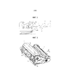
На фиг. 1 представлен чертеж общей конфигурации, иллюстрирующий вариант осуществления устройства формирования изображения;In FIG. 1 is a drawing of a general configuration illustrating an embodiment of an image forming apparatus;
на фиг. 2 представлен чертеж, иллюстрирующий способ крепления и удаления блока обработки;in FIG. 2 is a drawing illustrating a method for attaching and removing a processing unit;
на фиг. 3 представлен вид в перспективе состояния, в котором картридж тонера крепят к блоку обработки;in FIG. 3 is a perspective view of a state in which a toner cartridge is attached to a processing unit;
на фиг. 4 представлен вид в перспективе состояния, в котором картридж тонера удаляют из блока обработки;in FIG. 4 is a perspective view of a state in which a toner cartridge is removed from a processing unit;
на фиг. 5 представлен чертеж вида с нижней стороны картриджа тонера;in FIG. 5 is a drawing of a view from the bottom of the toner cartridge;
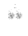
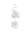
на фиг. 6 представлен вид в перспективе, иллюстрирующий конфигурацию на правой стороне блока обработки и картриджа тонера в состоянии, в котором картридж тонера крепят к блоку обработки, вид (a) на фиг. 6 - это чертеж, иллюстрирующий деблокированное состояние, а вид (b) на фиг. 6 - это чертеж, иллюстрирующий блокированное состояние;in FIG. 6 is a perspective view illustrating a configuration on the right side of the processing unit and the toner cartridge in a state in which the toner cartridge is attached to the processing unit, view (a) in FIG. 6 is a drawing illustrating a released state, and view (b) in FIG. 6 is a drawing illustrating a locked state;
на фиг. 7 представлен чертеж, иллюстрирующий вид изнутри конфигурации на правой стороне блока обработки и картриджа тонера в состоянии, в котором картридж тонера крепят к блоку обработки, вид (a) на фиг. 7 - это чертеж, иллюстрирующий деблокированное состояние, вид (b) на фиг. 7 - это чертеж, иллюстрирующий состояние во время блокировки, а вид (c) на фиг. 7 - это чертеж, иллюстрирующий блокированное состояние;in FIG. 7 is a drawing illustrating an inside view of the configuration on the right side of the processing unit and the toner cartridge in a state in which the toner cartridge is attached to the processing unit, view (a) in FIG. 7 is a drawing illustrating a released state, view (b) in FIG. 7 is a drawing illustrating a state during a lock, and view (c) in FIG. 7 is a drawing illustrating a locked state;
на фиг. 8 представлен чертеж, иллюстрирующий состояние во время блокировки, рассматриваемое с передней стороны картриджа тонера;in FIG. 8 is a drawing illustrating a state during a blockage viewed from a front side of a toner cartridge;
на фиг. 9 представлен чертеж, иллюстрирующий конфигурацию левой стороны картриджа тонера;in FIG. 9 is a drawing illustrating a configuration of a left side of a toner cartridge;
на фиг. 10 представлен вид в перспективе картриджа тонера в состоянии, в котором вход отработанного тонера открыт;in FIG. 10 is a perspective view of a toner cartridge in a state in which the waste toner input is open;
на фиг. 11 представлен вид в перспективе картриджа тонера в состоянии, в котором вход отработанного тонера закрыт;in FIG. 11 is a perspective view of a toner cartridge in a state in which the waste toner input is closed;
на фиг. 12 представлен вид в перспективе соответствующей части блока обработки в состоянии, в котором выход отработанного тонера закрыт;in FIG. 12 is a perspective view of a corresponding part of a processing unit in a state in which the waste toner output is closed;
на фиг. 13 представлен вид в перспективе соответствующей части блока обработки в состоянии, в котором выход отработанного тонера открыт;in FIG. 13 is a perspective view of a corresponding part of a processing unit in a state in which the waste toner output is open;
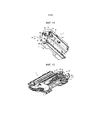
на фиг. 14 представлен вид в перспективе картриджа тонера, иллюстрирующий положение размещения затвора выхода пополняющего тонера;in FIG. 14 is a perspective view of a toner cartridge illustrating a placement position of a replenishing toner output shutter;
на фиг. 15 представлен вид в перспективе блока обработки, иллюстрирующий положение размещения связывающего элемента;in FIG. 15 is a perspective view of a processing unit illustrating a placement position of a connecting member;
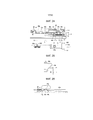
на фиг. 16 представлено сечение картриджа тонера, вид (a) на фиг. 16 - это чертеж, иллюстрирующий состояние, в котором выход пополняющего тонера закрыт, а вид (b) на фиг. 16 - это чертеж, иллюстрирующий состояние, в котором выход пополняющего тонера открыт;in FIG. 16 is a sectional view of a toner cartridge, view (a) in FIG. 16 is a drawing illustrating a state in which the refill toner output is closed, and view (b) in FIG. 16 is a drawing illustrating a state in which a replenishing toner output is open;
на фиг. 17 представлен вид сбоку картриджа тонера и блока обработки в состоянии, в котором выход пополняющего тонера закрыт;in FIG. 17 is a side view of the toner cartridge and the processing unit in a state in which the output of the replenishing toner is closed;
на фиг. 18 представлен вид сбоку картриджа тонера и блока обработки в состоянии, в котором выход пополняющего тонера открыт;in FIG. 18 is a side view of a toner cartridge and a processing unit in a state in which the replenishing toner output is open;
на фиг. 19 представлен вид в перспективе, иллюстрирующий сочлененное состояние исполнительного элемента, затвора и связывающего элемента, когда картридж тонера крепят к проявочному устройству блока обработки;in FIG. 19 is a perspective view illustrating an articulated state of an actuator, a shutter, and a connecting element when a toner cartridge is attached to a developing device of a processing unit;
на фиг. 20 представлен вид сбоку, иллюстрирующий сочлененное состояние исполнительного элемента, затвора и связывающего элемента, когда картридж тонера крепят к проявочному устройству блока обработки;in FIG. 20 is a side view illustrating an articulated state of an actuator, a shutter, and a connecting element when a toner cartridge is attached to a developing device of a processing unit;
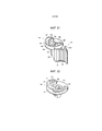
на фиг. 21 представлен чертеж, иллюстрирующий состояние, в котором технологический картридж, который включает в себя картридж тонера и блок обработки как единое целое, поднимают;in FIG. 21 is a drawing illustrating a state in which a process cartridge that includes a toner cartridge and a processing unit as a whole is raised;
на фиг. 22 представлен чертеж, иллюстрирующий конфигурацию механизма открывания и закрывания затвора, установленного на правую сторону проявочного устройства, вид (a) на фиг. 22 - это чертеж, иллюстрирующий состоянии, в котором основной корпус затвор расположен в положении закрывания, а вид (b) на фиг. 22 - это чертеж, иллюстрирующий состоянии, в котором основной корпус затвор расположен в положении открывания;in FIG. 22 is a drawing illustrating a configuration of a shutter opening and closing mechanism mounted on a right side of a developing device, view (a) in FIG. 22 is a drawing illustrating a state in which the main body of the shutter is in the closing position, and view (b) in FIG. 22 is a drawing illustrating a state in which the main body of the shutter is located in the opening position;
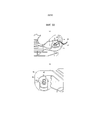
на фиг. 23 представлен чертеж, иллюстрирующий блокировочный механизм затвора входа пополняющего тонера;in FIG. 23 is a drawing illustrating a locking mechanism of an input shutter of a replenishing toner;
на фиг. 24 представлен чертеж, иллюстрирующий конфигурацию правой стороны проявочного устройства и картриджа тонера;in FIG. 24 is a drawing illustrating a configuration of a right side of a developing device and a toner cartridge;
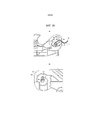
на фиг. 25 представлен чертеж, иллюстрирующий состояние, в котором прижимающая поверхность картриджа тонера упирается в прижимаемый участок основного корпуса затвора;in FIG. 25 is a drawing illustrating a state in which a pressing surface of a toner cartridge abuts against a pressing portion of a shutter main body;
на фиг. 26 представлен чертеж, иллюстрирующий механизм снятия блокировки затвора входа пополняющего тонера;in FIG. 26 is a drawing illustrating a mechanism for unlocking a shutter of an input of a replenishing toner;
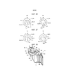
на фиг. 27 представлен чертеж, иллюстрирующий операцию открывания затвора входа пополняющего тонера;in FIG. 27 is a drawing illustrating an operation of opening a shutter of an input of a replenishing toner;
на фиг. 28 представлен чертеж, иллюстрирующий операцию закрывания затвора входа пополняющего тонера;in FIG. 28 is a drawing illustrating an operation of closing a shutter of an input of a replenishing toner;
на фиг. 29 представлен вид в перспективе, иллюстрирующий правую сторону технологического картриджа;in FIG. 29 is a perspective view illustrating the right side of a process cartridge;
на фиг. 30 представлено сечение контура опорных участков;in FIG. 30 is a cross-sectional view of the contour of support sections;
на фиг. 31 представлен вид в перспективе исполнительного элемента;in FIG. 31 is a perspective view of an actuator;
на фиг. 32 представлен вид в перспективе второго вводимого в зацепление участка;in FIG. 32 is a perspective view of a second engaging portion;
на фиг. 33 представлен чертеж, иллюстрирующий состояние предварительного удержания, вид (a) на фиг. 33 иллюстрирует вид сбоку первого вводимого в зацепление участка, а вид (b) на фиг. 33 - это вид сбоку второго вводимого в зацепление участка;in FIG. 33 is a drawing illustrating a pre-hold state, view (a) of FIG. 33 illustrates a side view of a first engaging portion, and view (b) of FIG. 33 is a side view of a second engagement portion;
на фиг. 34 представлен чертеж, иллюстрирующий блокированное состоянии, вид (a) на фиг. 34 иллюстрирует вид сбоку первого вводимого в зацепление участка, а вид (b) на фиг. 34 - это вид сбоку второго вводимого в зацепление участка;in FIG. 34 is a drawing illustrating a locked state, view (a) of FIG. 34 illustrates a side view of a first engaging portion, and view (b) of FIG. 34 is a side view of a second engagement portion;
на фиг. 35 представлен чертеж, иллюстрирующий состояние неудовлетворительного крепления, вид (a) на фиг. 35 иллюстрирует вид сбоку первого вводимого в зацепление участка, а вид (b) на фиг. 35 - это вид сбоку второго вводимого в зацепление участка;in FIG. 35 is a drawing illustrating an unsatisfactory fastening state, view (a) in FIG. 35 illustrates a side view of a first engaging portion, and view (b) of FIG. 35 is a side view of a second engagement portion;
на фиг. 36 представлен чертеж, иллюстрирующий позиционную взаимосвязь между вводимыми в зацепление участками и опорными участками в состоянии нормального крепления, вид (a) на фиг. 36 - это сечение в состоянии предварительного удержания, а вид (b) на фиг. 36 - это сечение в блокированном состоянии после срабатывания исполнительного элемента;in FIG. 36 is a drawing illustrating a positional relationship between the engaging portions and the support portions in the normal attachment state, view (a) in FIG. 36 is a section in a preliminary holding state, and view (b) in FIG. 36 is a section in a locked state after actuation of an actuator;
на фиг. 37 представлен чертеж, иллюстрирующий позиционную взаимосвязь между вводимыми в зацепление участками и опорными участками в состоянии неудовлетворительного крепления, вид (a) на фиг. 37 - это сечение в состоянии предварительного удержания, а вид (b) на фиг. 37 - это сечение в блокированном состоянии после срабатывания исполнительного элемента;in FIG. 37 is a drawing illustrating the positional relationship between the engaging portions and the support portions in an unsatisfactory attachment state, view (a) in FIG. 37 is a section in a preliminary holding state, and view (b) in FIG. 37 is a cross-section in a locked state after actuation of the actuator;
на фиг. 38 представлен вид в перспективе, иллюстрирующий второй вариант осуществления исполнительного элемента;in FIG. 38 is a perspective view illustrating a second embodiment of an actuator;
на фиг. 39 представлен вид в перспективе второго варианта осуществления второго вводимого в зацепление участка;in FIG. 39 is a perspective view of a second embodiment of a second engaging portion;
на фиг. 40 представлен чертеж, иллюстрирующий блокированное состояние в соответствии со вторым вариантом осуществления, вид (a) на фиг. 40 - вид сбоку первого вводимого в зацепление участка, а вид (b) на фиг. 40 - это вид сбоку второго вводимого в зацепление участка;in FIG. 40 is a drawing illustrating a locked state in accordance with a second embodiment, view (a) in FIG. 40 is a side view of a first engaging portion, and view (b) of FIG. 40 is a side view of a second engagement portion;
на фиг. 41 представлен чертеж, иллюстрирующий состояние предварительного удержания в соответствии со вторым вариантом осуществления, вид (a) на фиг. 41 - вид сбоку первого вводимого в зацепление участка, а вид (b) на фиг. 41 - это вид сбоку второго вводимого в зацепление участка;in FIG. 41 is a drawing illustrating a pre-hold state according to a second embodiment, view (a) in FIG. 41 is a side view of a first engaging portion, and view (b) of FIG. 41 is a side view of a second engagement portion;
на фиг. 42 представлен чертеж общей конфигурации устройства формирования цветного изображения с непрямым переносом; иin FIG. 42 is a drawing of an overall configuration of an indirect transfer color image forming apparatus; and
на фиг. 43 представлен чертеж общей конфигурации устройства формирования цветного изображения с прямым переносом.in FIG. 43 is a drawing of a general configuration of a direct transfer color image forming apparatus.
На фиг. 44 представлено сечение картриджа тонера, оснащенного захватываемым приспособлением.In FIG. 44 is a cross-sectional view of a toner cartridge equipped with a gripping device.
Описание вариантов осуществленияDescription of Embodiments
Первый вариант осуществленияFirst Embodiment
Ниже приводится пояснение данного изобретения со ссылками на прилагаемые чертежи.The following is an explanation of the present invention with reference to the accompanying drawings.
В данном случае, на чертежах, используемых при пояснении данного изобретения, для обозначения составляющих элементов, таких, как функциональные элементы, или составляющих компонентов, таких, как функциональные элементы, выполняющих одну и ту же функцию или имеющих одну и ту же форму, употребляются одни и те же позиции, чтобы достичь максимальной степени различия и не повторять пояснение после того, как оно однажды уже дано.In this case, in the drawings used in the explanation of the present invention, the same elements are used to designate constituent elements, such as functional elements, or constituent components, such as functional elements that perform the same function or have the same shape. and the same positions in order to achieve the maximum degree of difference and not to repeat the explanation after it has already been given once.
На фиг. 1 представлен чертеж общей конфигурации, иллюстрирующий вариант осуществления устройства формирования изображения. Прежде всего, ниже, со ссылками на фиг. 1, поясняется общая конфигурация и операции устройства формирования изображения.In FIG. 1 is a drawing of a general configuration illustrating an embodiment of an image forming apparatus. First of all, below, with reference to FIG. 1, the general configuration and operations of the image forming apparatus are explained.
Устройство формирования изображения, проиллюстрированное на фиг. 1, представляет собой устройство формирования монохроматического изображения. В основном корпусе 100 устройства (основном корпусе устройства формирования изображения) установлен с возможностью снятия блок 1 обработки, функционирующий как блок формирования изображения. Блок 1 обработки включает в себя фоточувствительный элемент 2, который функционирует как носитель изображения, предназначенный для того, чтобы нести изображение на своей поверхности; зарядный валик 3, который функционирует как зарядный блок для зарядки поверхности фоточувствительного элемента 2; проявочное устройство 4, которое функционирует как проявочный блок преобразования скрытого (латентного) изображения, сформированного на фоточувствительном элементе 2, в видимое изображение; и ракельный нож 5, который функционирует как очистной блок для очистки внешней поверхности фоточувствительного элемента 2. Кроме того, в положении напротив фоточувствительного элемента 2 находится матрица 6 головок СИДов (СИДы - это светоизлучающие диоды), которая функционирует как экспонирующий блок для воздействия светом на внешнюю поверхность фоточувствительного элемента 2.The image forming apparatus illustrated in FIG. 1 is a monochromatic imaging device. In the
Помимо этого, картридж 7 тонера, который служит в качестве контейнера тонера, крепится с возможностью открепления к верхней поверхности (установочному участку) проявочного устройства 4 блока 1 обработки. Картридж 7 тонера имеет корпус 22 контейнера, который включает в себя блок 8, содержащий тонер, для заключения в тем тонера, который является тонером, подаваемым в проявочное устройство 4. Кроме того, в данном варианте осуществления, картридж 7 тонера также включает в себя выполненный как единое целое с ним блок 9 сбора тонера, собирающий тонер, удаленный ракельным ножом 5 (т.е., собирающий отработанный тонер).In addition, the
Кстати, устройство формирования изображения также включает в себя: устройство 10 переноса, которое переносит изображение на лист бумаги, служащий в качестве носителя записи; бумагоподающее устройство 11, которое подает листы бумаги; фиксирующее устройство 12, которое фиксирует изображение, перенесенное на лист бумаги, на листе бумаги; и бумаговыпускное устройство 13, которое выпускает лист бумаги наружу из устройства формирования изображения.By the way, the image forming apparatus also includes: a
Устройство 10 переноса включает в себя валик 14 переноса, функционирующий как переносящий элемент. В состоянии, в котором блок 1 обработки установлен в основном корпусе 100 устройства, валик 14 переноса упирается в фоточувствительный элемент 2. В результате, на участке, где упираются друг в друга валик 14 переноса и фоточувствительный элемент 2, между ними образуется зона контакта при переносе. Вдобавок к этому, валик 14 переноса соединен с источником питания (не изображен), из которого на него подается заданное напряжение постоянного тока (DC) или заданное напряжение переменного тока (AC).The
Бумагоподающее устройство 11 включает в себя бумагоподающую кассету 15, в которой заключены листы Р бумаги, и бумагоподающий валик 16, который подает листы Р бумаги, заключенные в бумагоподающей кассете 15. Со стороны бумагоподающего валика 16, находящейся дальше по ходу в направлении транспортировки бумаги, находится пара валиков 17 приводки, которая служит в качестве пары тактирующих валиков для синхронизации тактирования транспортировки и осуществляемой в соответствии с ним транспортировки листа бумаги в зону контакта при вспомогательном переносе. Кстати, примеры листа Р бумаги включают в себя лист картона, открытку, конверт, лист простой бумаги, лист тонкой бумаги, лист бумаги с покрытием (такой, как лист простой мелованной бумаги или лист мелованной бумаги для художественной печати) или лист чертежной кальки. Кроме того, что касается носителей записи помимо листов бумаги, то возможно использование листов для ДП или пленок для ДП (ДП - диапроектор).The
Фиксирующее устройство 12 включает в себя фиксирующий валик 18, функционирующий как фиксирующий элемент, и прижимной валик 19, функционирующий как прижимной элемент. Фиксирующий валик 18 нагревается источником тепла, таким, как нагреватель (не изображен). Прижимной валик 19 прижимается к фиксирующему валику 18 и упирается в фиксирующий валик 18. В результате, в месте упора образуется зона контакта при фиксации.The locking
Бумаговыпускное устройство 13 включает в себя пару бумаговыпускных валиков 20. Лист бумаги, который выпускается наружу из устройства формирования изображения посредством бумаговыпускных валиков 20, укладывается в стопу на улавливающий лоток 21, который образован посредством создания впадины на верхней поверхности основного корпуса 100 устройства.The
Далее, со ссылками на фиг. 1, ниже приводится пояснение операции формирования изображения, осуществляемой в устройстве формирования изображения в соответствии с данным вариантом осуществления.Next, with reference to FIG. 1, an explanation is given of an image forming operation carried out in the image forming apparatus in accordance with this embodiment.
Как только начинается операция формирования изображения, фоточувствительный элемент 2 приводится во вращение, а поверхность фоточувствительного элемента 2 равномерно заряжается, приобретая заданную полярность. Затем, на основании информации об изображении, принимаемой из устройства считывания (не изображено) или компьютера (не изображен), заряженная поверхность фоточувствительного элемента 2 подвергается воздействию света из матрицы 6 головок СИДов. В результате, на заряженной поверхности фоточувствительного элемента 2 формируется электростатическое скрытое изображение. Потом проявочное устройство 4 подает тонер на электростатическое скрытое изображение, сформированное на фоточувствительном элементе 2. В результате, электростатическое скрытое изображение проявляется как тонерное изображение (т.е., преобразуется в видимое изображение).As soon as the image forming operation begins, the
Кстати, как только начинается операция формирования изображения, начинается привод бумагоподающего валика 16 во вращение таким образом, что из бумагоподающей кассеты 15 подается лист Р бумаги. Однако на валиках 17 приводки дальнейшая транспортировка листа Р бумаги временно останавливается. Затем, в заданный момент времени, начинается привод во вращение валиков 17 приводки, которые транспортируют лист Р бумаги в зону контакта при переносе синхронно с моментом времени, когда тонерное изображение, сформированное на фоточувствительном элементе 2, достигает зоны контакта при переносе.By the way, as soon as the image forming operation begins, the
В этот момент, к валику 14 переноса прикладывается напряжение переноса, которое имеет полярность, противоположную полярности зарядки тонером, полученной для тонерного изображения, сформированного на фоточувствительном элементе 2. В результате, в месте переноса формируется переносящее электрическое поле. Под действием переносящего электрического поля, тонерное изображение, сформированное на фоточувствительном элементе 2, переносится на лист Р бумаги. Потом остаточный тонер, который не перенесен на лист Р бумаги и который остается на фоточувствительном элементе 2, удаляется ракельным ножом 5 и собирается блоком 9 сбора тонера в картридже 7 тонера.At this point, a transfer voltage is applied to the
Лист Р бумаги, на который перенесено тонерное изображение, затем транспортируется в фиксирующее устройство 12 и проходит через зону контакта при фиксации, образованную между фиксирующим валиком 18 и прижимным валиком 19. В результате, лист Р бумаги нагревается и подвергается воздействию давления, а тонерное изображение фиксируется на лист Р бумаги. Потом лист Р бумаги выпускается бумаговыпускными валиками 20 наружу из устройства формирования изображения и укладывается стопой в улавливающем лотке 21.The sheet P of paper onto which the toner image is transferred is then transported to the fixing
На фиг. 2 представлен чертеж, иллюстрирующий способ прикрепления и удаления блока обработки.In FIG. 2 is a drawing illustrating a method of attaching and removing a processing unit.
Как изображено на фиг. 2, в данном варианте осуществления к переднему участку основного корпуса 100 устройства крепится крышка 10, выполненная по своей сути открываемой и закрываемой. Когда крышку 101 держат открытой, достигается возможность отвода матрицы 6 головок СИДов назад посредством связывающего механизма (не изображен). При такой конфигурации, когда крышку 101 держат открытой, блок 1 обработки можно удалить с передней стороны устройства формирования изображения (т.е., со стороны, обращенной к направлению перемещения выпускаемого листа Р бумаги, или - если обратиться к фиг. 2 - с правой стороны), не задевая матрицу 6 головок СИДов. При этом, в состоянии, в котором картридж 7 тонера прикреплен к блоку 1 обработки, картридж 7 тонера и блок 1 обработки можно удалять как цельный технологический картридж с передней стороны основного корпуса 100 устройства. Помимо этого, независимо от того, прикреплен блок 1 обработки к основному корпусу 100 устройства, или удален из основного корпуса 100 устройства, картридж 7 тонера можно крепить к блоку 1 обработки или удалять из него.As shown in FIG. 2, in this embodiment, a
На фиг. 3 представлен вид в перспективе состояния, в котором картридж тонера крепят к блоку обработки. На фиг. 4 представлен вид в перспективе состояния, в котором картридж тонера удаляют из блока обработки.In FIG. 3 is a perspective view of a state in which a toner cartridge is attached to a processing unit. In FIG. 4 is a perspective view of a state in which a toner cartridge is removed from the processing unit.
Обращаясь к фиг. 3, отмечаем, что направление, обозначенное стрелкой A1, представляет собой направление крепления во время крепления блока 1 обработки и картриджа 7 тонера к основному корпусу 100 устройства. Кроме того, направление, обозначенное стрелкой A2, представляет собой направление удаления во время удаления блока 1 обработки и картриджа 7 тонера из основного корпуса 100 устройства.Turning to FIG. 3, we note that the direction indicated by arrow A1 represents the direction of attachment during the attachment of the
В нижеследующем пояснении, в картридже 7 тонера и блоке 1 обработки, передняя сторона направления А1 крепления (или передняя сторона направления В1 крепления) называется дальней стороной, а задняя сторона, противоположная передней стороне, называется ближней стороной. Кроме того, правая сторона и левая сторона определены как обращенные к передней стороне направления А1 крепления (или направления В1 крепления).In the following explanation, in the
На ближней стороне в направлении крепления картриджа 7 тонера находится захватываемое приспособление 25, которое оператор может захватывать, крепя картридж 7 тонера к основному корпусу 100 устройства или блоку 1 обработки или удаляя картридж 7 тонера оттуда. Захватываемое приспособление 25 крепят с возможностью поворота относительно вала 35 (см. фиг. 4), который представляет собой колоннообразный стержень, расположенный параллельно продольному направление корпуса 22 контейнера. Во время удаления картриджа 7 тонера и блока 1 обработки из основного корпуса 100 устройства или во время удаления картриджа 7 тонера из блока 1 обработки, как изображено на фиг. 4, захватываемое приспособление 25 повернуто к ближней стороне, так что появляется возможность захвата захватываемого приспособления 25. С другой стороны, после крепления картриджа 7 тонера и блока 1 обработки к основному корпусу 100 устройства, как изображено на фиг. 7, захватываемое приспособление 25 повернуто к дальней стороне, так что появляется возможность удержания захватываемого приспособления 25 в заключенном состоянии. Кроме того, центр поворота захватываемого приспособления 25 (т.е., вала 35) предписан находящимся ниже центра G тяжести захватываемого приспособления 25 (см. виды (a) и (b) на фиг. 16). Поэтому в прикрепленном состоянии блока 1 обработки, как изображено на фиг. 2, даже если оператор забудет повернуть захватываемое приспособление 25 к дальней стороне, крышку 101 можно поворачивать снизу до тех пор она не коснется захватываемого приспособления 25, после чего можно повернуть захватываемое приспособление 25 вместе с ней, поддерживая его в заключенном состоянии.On the near side in the direction of attachment of the
Отметим, что вышеупомянутое захватываемое приспособление может не быть поворотным, а может крепиться к крышке 101 при условии, что наличия у захватываемого приспособления такого размера, при котором крышку 101 можно закрывать так, что захватываемое приспособление не коснется крышки. Фиг. 44 иллюстрирует захватываемое приспособление 250 в еще одном варианте осуществления. Захватываемое приспособление 250 расположено по центру в продольном направлении корпуса контейнера и выше вала 35. При этой конструкции, оператор также может переносить картридж 7 тонера и блок 1 обработки как цельный технологический картридж, удерживая его так, как изображено на фиг. 21.Note that the aforementioned gripping device may not be rotatable, but may be attached to the
Ниже, со ссылками на фиг. 3-16 приводится более подробное пояснение, касающееся конфигурации картриджа 7 тонера и блока 1 обработки.Below, with reference to FIG. 3-16, a more detailed explanation is given regarding the configuration of the
Как изображено на фиг. 4, на правой стороне 22a корпуса 22 контейнера находится исполнительный элемент 26, который выполнен с возможностью вращения. Исполнительный элемент 26 крепится к правому концу вала 35 и вращается вместе с валом 35. Чтобы сделать вал 35 вращающимся относительно корпуса 22 контейнера, вал 35 оперт с возможностью вращения в подшипниках 27a и 27b (см. фиг. 5) на обоих концах корпуса 22 контейнера.As shown in FIG. 4, on the
Как изображено на фиг. 6 и 7, исполнительный элемент 26 включает в себя выполненный как единое целое с ним рычаг 57 и первый вводимый в зацепление участок 58, который вращается вместе с валом 35. Рычаг 57 включает в себя: фиксирующий участок 26a, к которому крепится вал 35; продолжающий участок 26b, который проходит от фиксирующего участка 26a в направлении, перпендикулярном направлению оси вала 35; и пластинчатый участок 26c, который, если смотреть с направления оси вала 35, изгибается от продолжающего участка 26b и проходит дальше. Иными словами, пластинчатый участок 26c проходит под углом относительно радиального направления из центра вала 35.As shown in FIG. 6 and 7, the actuating
Как изображено на фиг. 14, первый вводимый в зацепление участок 58 включает в себя выполненный как единое целое с ним и находящийся на одном конце вала 35 участок 58a планшайбы, который является дисковидным и проходит в направлении, перпендикулярном направлению оси вала 35, и надстроечный участок 58b, который надстроен от участка 58а планшайбы в направлении оси вала 35. Как изображено на фиг. 20, надстроечный участок 58b проходит в окружном направление участка 58а планшайбы и имеет двустенную структуру, оба конца которой в окружном направлении замкнуты. Надстроечный участок 58b имеет внешнюю стенку 581 на радиально внешней стороне и имеет внутреннюю стенку 582 на радиально внутренней стороне. Участок между двумя концами в окружном направлении надстроечного участка 58b открыт в направлении, перпендикулярном направлению оси, а внутренняя периферия внутренней стенки 582 образует первую вводимую в зацепление поверхность 58c, которая имеет U-образный край, если смотреть с направления оси. Исполнительный элемент 26 крепится к одному концу вала 35 вершинами надстроечного участка 58b первого вводимого в зацепление участка 58, обращенными наружу. Во время крепления картриджа 7 тонера к блоку 1 обработки, опорный участок 54 (см. фиг. 29), который представляет собой бобышку и расположен на правой стороне 1a блока 1 обработки, вводится в зацепление с первой вводимой в зацепление поверхностью 58c. В данном случае, при условии, что первый вводимый в зацепление участок 58 способен поворачиваться вместе с рычагом 57, он может иметь произвольную конфигурацию. Таким образом, помимо конфигурации, поясненной выше, в которой рычаг 57 и первый вводимый в зацепление участок 58 выполнены как единое целое, можно также реализовать рычаг 57 и первый вводимый в зацепление участок 58 как отдельные элементы и крепить их к валу 35 по отдельности.As shown in FIG. 14, the
Таким образом, картридж 7 тонера можно крепить к блоку 1 обработки посредством поворота исполнительного элемента 26. Конкретнее, как изображено на виде (a) фиг. 6, на правой вершине пластинчатого участка 26c исполнительного элемента 26 сформирован блокирующий участок 26c1 в виде выступа, который может входить в зацепление с вводимым в зацепление участком 1c, который выполнен как вводимый в зацепление участок обращенной к установочном участку стороны на правой стороне 1a блока 1 обработки. Сторона 1a - это внутренняя поверхность стенки, противоположная правой стороне картриджа 7 тонера.Thus, the
Иными словами, вводимый в зацепление участок 1c выполнен на вышеупомянутой внутренней поверхности стенки и служит в качестве направляющей канавки, в которую можно вводить выступ блокирующего участка 26c1. Вводимый в зацепление участок 1c: включает в себя открытый участок 1c1, с которого канавка начинается и проходит в правую сторону 1a от ближней вертикальной стороны правой стороны 1a; включает в себя криволинейный участок 1c2, на котором канавка изгибается в середине; и открытый участок 1c3, из которого канавка выходит к верхней горизонтальной стороне 1a. Кроме того, если смотреть с направления оси вала 35, из двух поверхностей канавки вводимого в зацепление участка 1c, боковая поверхность, которая дальше от центральной оси и которая проходит от открытого участка 1c1 к криволинейному участку 1c2, служит в качестве поверхности 1c4 скольжения, по которой, скользя, движется блокировочный участок 26c1. Кроме того, имеется вводимая в зацепление поверхность 1c5, которая соединена со поверхностью 1c4 скольжения и которая проходит в вертикальном направлении от криволинейного участка 1c2 до открытого участка 1c3, с которой вводится в зацепление блокировочный участок 26c1.In other words, the engaged
Ниже приводится пояснение последовательности операций исполнительного элемента 26 в состоянии, в котором картридж 7 тонера крепят к блоку 1 обработки.The following is an explanation of the sequence of operations of the
Сначала, как изображено на фиг. 6(a) и фиг. 7(a), в состоянии, в котором картридж 7 тонера прикреплен к блоку 1 обработки, но еще не сблокирован с ним, оператор либо удерживает верх и низ пластинчатого участка 26c исполнительного элемента 26 пальцами, или прижимает пластинчатый участок 26c снизу, прикладывая силу прижима к исполнительному элементу 26, и поворачивает исполнительный элемент 26, прижимая его к дальней стороне. В результате, блокировочный участок 26c1 достигает открытого участка 1c1 на ближней вертикальной стороне вводимого в зацепление участка 1c. Кроме того, если к пластинчатому участку 26c исполнительного элемента 26 прикладывают силу прижима, чтобы повернуть его к дальней стороне, то, как изображено на фиг. 7(b), блокировочный участок 26c1 движется, контактируя с поверхностью 1с скольжения (скользя по ней). Ввиду контакта между блокировочным участком 26c1 и поверхностью 1c4 скольжения, в направлении, противоположном направлению силы Х прижима, прикладываемой к исполнительному элементу 26, прикладывается сила J торможения (т.е., прикладываемая сила J торможения противодействует силе Х прижима). В данном случае, пластинчатый участок 26c выполнен с единственной пластиной из полимера, такого, как полистирол, упруго деформируемого до некоторой степени. Поэтому, как изображено на фиг. 8, пластинчатый участок 26c оказывается прижатым с возможностью деформации к дальней стороне от блокировочного участка 26c1 как точки поворота. Потом, как изображено на фиг. 7(c), как только блокировочный участок 26c1 достигает криволинейного участка 1c2, наступает окончание состояния скольжения блокировочного участка 26c1 относительно поверхности 1с4 скольжения, и блокировочный участок 26c1 упирается во вводимую в зацепление поверхность 1c5. Таким образом, состояние, в котором блокировочный участок 26c1 оказывается упертым во вводимую в зацепление поверхность 1c5, является блокированным состоянием. Кроме того, в блокированном состоянии пластинчатый участок 26c освобождается из упруго деформированного состояния и возвращается к исходной форме. Помимо этого, пластинчатый участок 26c приобретает такую ориентацию, что блокировочный участок 26c1 оказывается упертым во вводимую в зацепление поверхность 1c5. При этом, даже если прикладывается неожиданная сила, тем самым вызывая поворот пластинчатого участка 26c исполнительного элемента 26 к ближней стороне, пластинчатый участок 26c не подвергается деформации, пока не прикладывается существенно большая сила. Следовательно, блокировочный участок 26c1 также не движется по вводимой в зацепление поверхности 1c5.First, as shown in FIG. 6 (a) and FIG. 7 (a), in a state in which the
С другой стороны, если оператор прижимает пластинчатый участок 26c сверху с помощью пальцев и поворачивает исполнительный элемент 26 к ближней стороне, то пластинчатый участок 26c подвергается упругой деформации со стороны блокировочного участка 26c1 как точки поворота и в направлении, противоположном имеющему место в случае, в котором он прижимается к дальней стороне, как описано выше. Затем зацепление между блокировочным участком 26c1 и вводимым в зацепление участком 1c устраняется, и происходит переход к состоянию устраненной блокировки.On the other hand, if the operator presses the
Кстати, как изображено на фиг. 4, на правой стороне 22a корпуса 22 контейнера размещен позиционирующий выступ 29 в виде цилиндрического выступа с целью определения положения картриджа 7 тонера относительно блока 1 обработки. Точно так же, на левой стороне 22b корпуса 22 контейнера, как изображено на фиг. 10, находится позиционирующий выступ 31 в виде выступа, имеющего поперечное сечение в форме полумесяца с целью определения положения картриджа 7 тонера относительно блока 1 обработки. Соответственно, на правой стороне 1a и левой стороне 1b блока 1 обработки соответственно выполнены направляющие участки 30 и 32 типа канавок (см. фиг. 4) таким образом, что криволинейные поверхности позиционирующих выступов 29 и 31 упираются в направляющие участки 30 и 32.By the way, as shown in FIG. 4, on the
Как изображено на фиг. 10, на левой стороне 22b корпуса 22 контейнера, второй вводимый в зацепление участок 34 крепится с возможностью поворота. Идентично первому вводимому в зацепление участку 58, второй вводимый в зацепление участок 34 включает в себя выполненный как единое целое с ним участок 34a планшайбы, который является дисковидным и проходит в направлении, перпендикулярном направлению оси вала 35, и надстроечный участок 34b, который надстроен от участка 34а планшайбы в направлении оси вала 35. Надстроечный участок 34а крепится к другому концу вала 35. Надстроечный участок 34b проходит в окружном направление участка 34a планшайбы и имеет двустенную структуру, оба конца которой в окружном направлении замкнуты. Поэтому надстроечный участок 34b имеет внешнюю стенку 341 на радиально внешней стороне и имеет внутреннюю стенку 342 на радиально внутренней стороне. Участок между двумя концами в окружном направлении надстроечного участка 34b открыт в направлении, перпендикулярном направлению оси, а внутренняя периферия внутренней стенки 342 образует вторую вводимую в зацепление поверхность 34c, которая имеет U-образный край, если смотреть с направления оси. Во время крепления картриджа 7 тонера к блоку 1 обработки, опорный участок 33 (см. фиг. 4), который представляет собой бобышку и расположен на правой стороне 1b блока 1 обработки, вводится в зацепление со второй вводимой в зацепление поверхностью 34c.As shown in FIG. 10, on the
В данном варианте осуществления, второй вводимый в зацепление участок 4 сочленен с валом 35 (см. фиг. 4), с которым также сочленен исполнительный элемент 26. Таким образом, когда исполнительный элемент 26 поворачивают в направлении вперед или назад, второй вводимый в зацепление участок 34 также поворачивается вместе с ним в направлении вперед или назад. Кроме того, в данном варианте осуществления, захватываемое приспособление 25 также крепится к валу 35, который сочленяет первый вводимый в зацепление элемент 34 и исполнительный элемент 26. Вместе с тем, конфигурация захватываемого приспособления 25 обеспечивает возможность поворота независимо от вала 35 и позволяет не работать совместно с исполнительным элементом 26.In this embodiment, the second
Как изображено на фиг. 5, между валом 35 и корпусом 22 контейнера находится цилиндрическая винтовая пружина 28, работающая на кручение. Из-за цилиндрической винтовой пружины 28, работающей на кручение, в направлении по часовой стрелке - см. фиг. 9 - смещается не только вал 35, но и исполнительный элемент 26 (первый вводимый в зацепление участок 58) и второй вводимый в зацепление участок 34, которые сочленены с валом 35, также смещаются в направлении по часовой стрелке - см. фиг. 9. Кроме того, при использовании упора, который оказывает сопротивление смещению, вызываемому цилиндрической винтовой пружиной 28, работающей на кручение, первый вводимый в зацепление участок 58 и второй вводимый в зацепление участок 34 удерживаются в заданных ориентациях. Конкретнее, в естественном состоянии, в котором к исполнительному элементу 26 не прикладывается внешняя сила, первый вводимый в зацепление участок 58 и второй вводимый в зацепление участок 34 удерживаются таким образом, что проемы между обоими концами надстроечных участков 58b и 34b, соответственно, обращены в направлении под острым углом вниз. В данном варианте осуществления, как изображено на фиг. 9, что касается направления проема второго вводимого в зацепление участка 34, когда картридж 7 тонера устанавливают на установочной поверхности Z, соответствующей горизонтальной плоскости, внутренняя периферия надстроечного участка 58b в окрестности поверхностей проема обращена в направлении, наклоненном к дальней стороне на 30° относительно вертикальной линии V. Как изображено на фиг. 14, направление проема первого вводимого в зацепление участка 58 также идентично направлению проема второго вводимого в зацепление участка 34 и наклонено к дальней стороне на 30° относительно вертикальной линии V.As shown in FIG. 5, a
Кроме того, как изображено на фиг. 10, с целью выпуска отработанного тонера внутрь (в блок 9 сбора тонера), на левой стороне 22b корпуса 22 контейнера выполнен вход 36 отработанного тонера в виде отверстия квадратной формы. Вход 36 отработанного тонера выполнен на дугообразном заглубленном участке, который выполнен под позиционирующим выступом 31 и имеет отверстие в направлении вверх. Вокруг входа 36 отработанного тонера наклеено уплотнение 36a, которое выполнено из губчатого материала. На верхней стороне уплотнения 36a расположен с возможностью поворота затвор 37 входа отработанного тонера (см. фиг. 11), так что он может скользить по верхней поверхности уплотнения 36a.In addition, as shown in FIG. 10, in order to discharge the waste toner inside (into the toner collection unit 9), an
Затвор 37 входа отработанного тонера является криволинейным, чтобы оказался возможным поворот вдоль дугообразного заглубленного участка 22d. Кроме того, в состоянии, в котором картридж 7 тонера поддерживается отдельно, затвор 37 входа отработанного тонера смещается смещающим элементом 37a, который является винтовой цилиндрической пружиной, работающей на кручение, в направлении поворота, в котором вход 36 отработанного тонера всегда остается закрытым. Смещающий элемент 37a находится между затвором 37 входа отработанного тонера и картриджем 7 тонера. Вращающийся вал затвора 37 входа отработанного тонера вставлен в винтовую цилиндрическую пружину, работающую на кручение (смещающий элемент 37a). Когда затвор 37 входа отработанного тонера поворачивается, становится возможным переход между открытым состоянием (состоянием, изображенным на фиг. 10), в котором вход 36 отработанного тонера открыт, и закрытым состоянием (состоянием, изображенным на фиг. 11), в котором вход 36 отработанного тонера закрыт. Как изображено на фиг. 12, около левой стороны 1b блока 1 обработки проложен, выдаваясь внутрь, канал 39 транспортировки отработанного тонера, имеющий трубчатую форму. На конце канала 39 транспортировки отработанного тонера находится выход 38 отработанного тонера, через который выпускается отработанный тонер и который имеет отверстие в направлении вниз. Кроме того, на внешнюю периферию конца канала 39 транспортировки отработанного тонера крепится затвор 40 выхода отработанного тонера с целью открывания и закрывания выхода 38 отработанного тонера. Конфигурация затвора 40 выхода отработанного тонера обеспечивает поворот вокруг центра вала. Таким образом, возможен переход между открытым состоянием (состоянием, изображенным на фиг. 13), в котором выход 38 отработанного тонера открыт, и закрытым состоянием (состоянием, изображенным на фиг. 12), в котором выход 38 отработанного тонера закрыт.The waste
Затвор 37 входа отработанного тонера смещается смещающим элементом 37a (см. фиг. 10), который выполнен из цилиндрической винтовой пружины, работающей на кручение, в направлении закрывания входа 36 отработанного тонера, тогда как затвор 40 выхода отработанного тонера смещается смещающим элементом 40a (см. фиг. 12), который выполнен из цилиндрической винтовой пружины, работающей на кручение, в направлении закрывания выхода 38 отработанного тонера. Кроме того, в затворе 40 выхода отработанного тонера выполнен выпуклый участок 41, с которым затвор 37 входа отработанного тонера контактирует во время крепления картриджа 7 тонера к блоку 1 обработки. Как только затвор 37 входа отработанного тонера вступает в контакт с выпуклым участком 41, затвор 37 входа отработанного тонера поворачивается в направлении, в котором открывается вход 36 отработанного тонера (в направлении стрелки, изображенной на фиг. 10), тогда как затвор 40 выхода отработанного тонера поворачивается в направлении, в котором открывается выход 38 отработанного тонера (в направлении стрелки, изображенной на фиг. 13). Затем, в состоянии, в котором картридж 7 тонера крепят к блоку 1 обработки, вход 36 отработанного тонера в открытом состоянии и выход 38 отработанного тонера в открытом состоянии располагаются друг против друга. Таким образом, в этом состоянии вход 36 отработанного тонера и выход 38 отработанного тонера сообщаются друг с другом. В результате, отработанный тонер, удаленный с внешней поверхности фоточувствительного элемента 2, можно выпускать в картридж 7 тонера (т.е., в блок 9 сбора тонера).The waste
И наоборот, в состоянии, в котором картридж 7 тонера удаляют из блока 1 обработки, контакт между затвором 37 входа отработанного тонера и выпуклым участком 41 прекращается, а затвор 37 входа отработанного тонера и затвор 40 выхода отработанного тонера поворачиваются в направлениях смещения соответствующих смещающих элементов (в направлениях стрелок, изображенных на фиг. 11 и 12, соответственно). В результате, вход 36 отработанного тонера и выход 38 отработанного тонера закрыты, тем самым предотвращая любую утечку тонера через вход 36 отработанного тонера и выход 38 отработанного тонера.Conversely, in the state in which the
Кстати, как изображено на фиг. 14, на криволинейной поверхности, имеющейся около правой стороны 22a корпуса 22 контейнера, выполнен выход 42 пополняющего тонера в виде отверстия квадратной формы с целью выпуска тонера, который содержится в блоке 8, содержащем тонер. Выход 42 пополняющего тонера имеет отверстие в направлении вниз. Кроме того, под выходом 42 пополняющего тонера расположен затвор 43 выхода пополняющего тонера, проходящий вдоль криволинейной поверхности (дугообразной поверхности) выхода 42 пополняющего тонера. Затвор 43 выхода пополняющего тонера можно использовать для открывания и закрывания выхода 42 пополняющего тонера. Затвор 43 выхода пополняющего тонера проходит с возможностью поворота вдоль криволинейной поверхности (дугообразной поверхности) выхода 42 пополняющего тонера и концентричен центральной линии цилиндрической формы позиционирующего выступа 29, который является цилиндрическим выступом.By the way, as shown in FIG. 14, on a curved surface near the
Затвор 43 выхода пополняющего тонера включает в себя выступ 43b, который выступает в направлении вращающегося вала затвора 43 выхода пополняющего тонера. Как изображено на фиг. 14, между затвором 43 выхода пополняющего тонера и правой стороной 22a, которая служит в качестве элемента крышки, скрывающего зубчатое колесо, находится цилиндрическая винтовая пружина 43c, работающая на кручение, которая служит в качестве смещающего элемента. Кроме того, на концевом участке цилиндрической винтовой пружины 43c, работающей на кручение, находится крюковой участок, который подвешен на выступе 43b. Таким образом, затвор 43 выхода пополняющего тонера смещается цилиндрической винтовой пружиной 43c, работающей на кручение, в направлении закрывания выхода 42 пополняющего тонера.The refill
Как изображено на фиг. 15, около правой стороны 1a проявочного устройства 4 блока 1 обработки на проявочном устройстве 4 находится вход 44 пополняющего тонера, имеющий отверстие в направлении вверх, с целью засыпки пополняющего тонера. Кроме того, в окрестности входа 44 пополняющего тонера находится затвор 45 входа пополняющего тонера. Когда затвор 45 входа пополняющего тонера осуществляет движение скольжения из стороны в сторону, вход 44 пополняющего тонера открывается и закрывается.As shown in FIG. 15, near the
На фиг. 16 представлено габаритное сечение картриджа тонера.In FIG. 16 shows the overall cross-section of a toner cartridge.
Как изображено на фиг. 16, в блоке 8, содержащем тонер, корпуса 22 контейнера, находится перемешивающая лопасть 46, которая служит в качестве перемешивающего элемента для перемешивания присутствующего тонера, и находится транспортирующий шнек 47, который служит в качестве транспортирующего элемента для транспортировки присутствующего тонера к выходу 42 пополняющего тонера. Кроме того, в блоке 9 сбора тонера корпуса 22 контейнера находится транспортирующий шнек 48, который служит в качестве транспортирующего элемента для транспортировки отработанного тонера внутрь блока 9 сбора тонера.As shown in FIG. 16, in the toner-containing
На транспортирующий шнек 47, транспортирующий шнек 48 и перемешивающую лопасть 46 посредством передаточного механизма передается движущая сила из источника движущей силы, который находится в основном корпусе 100 устройства. Конкретнее, в данном варианте осуществления, на правой стороне 22a корпуса 22 контейнера находится передаточный механизм привода в качестве блока передачи привода, который включает в себя муфту 49 (см. фиг. 4) и множество передаточных зубчатых колес, которые расположены за элементом 22а крышки и сцеплены с муфтой 49, транспортирующим шнеком 47, транспортирующим шнеком 48 и перемешивающей лопастью 46. Когда картридж 7 тонера (контейнер тонера) устанавливают в основном корпусе 100 устройства, передаточный элемент привода вводится в зацепление с муфтой 49. В результате, появляется возможность передачи движущей силы от источника движущей силы, находящегося в основном корпусе 100 устройства, на транспортирующий шнек 47, транспортирующий шнек 48 и перемешивающую лопасть 46.To the conveying
Как изображено на фиг. 16, затвор 43 выхода пополняющего тонер выполнен дугообразным вдоль трубчатой формы выхода 42 пополняющего тонера. На одной части затвора 43 выхода пополняющего тонера выполнено отверстие 43a с целью выпуска тонера. Кроме того, конфигурация затвора 43 выхода пополняющего тонера позволяет ему поворачиваться вдоль внешней периферии выхода 42 пополняющего тонера.As shown in FIG. 16, the
Как изображено на фиг. 16(a), когда затвор 43 выхода пополняющего тонера поворачивается в направлении против часовой стрелки - см. фиг. 16(a), выход 42 пополняющего тонера закрывается затвором 43 выхода пополняющего тонера. С другой стороны, как изображено на фиг. 16(b), когда затвор 43 выхода пополняющего тонера поворачивается в направлении по часовой стрелке - см. фиг. 16(b), отверстие 43a выхода 42 пополняющего тонера оказывается в положении, в котором оно сообщается с выходом 42 пополняющего тонера.As shown in FIG. 16 (a) when the refill
Кстати, исполнительный элемент 26, который выполняет функцию блокировки, как описано выше, дублирует в качестве элемента для открывания и закрывания затвор 43 выхода пополняющего тонера. Вместе с тем, исполнительный элемент 26 и затвор 43 выхода пополняющего тонера находятся на расстоянии друг от друга, а не соединены друг с другом непосредственно. То есть когда картридж 7 тонера (контейнер тонера) удерживается отдельно, исполнительный элемент 26 и затвор 43 выхода пополняющего тонера находятся в несочлененном состоянии. Следовательно, даже если исполнительный элемент 26 приведен в действие, открывание и закрывание затвора 43 выхода пополняющего тонера не происходит.By the way, the
Как изображено на фиг. 15, в данном варианте осуществления, в блоке 1 обработки находится связывающий элемент 51, посредством которого можно переводить исполнительный элемент 26 и затвор 43 выхода пополняющего тонера в сочлененное состояние.As shown in FIG. 15, in this embodiment, in the
Ниже, со ссылками на фиг. 17-20, приводится подробное пояснение конфигурации исполнительного элемента 26, затвора 43 выхода пополняющего тонера и связывающего элемента 51.Below, with reference to FIG. 17-20, a detailed explanation of the configuration of the
В нижеследующем пояснении, за исключением случаев конкретной необходимости, затвор 43 выхода пополняющего тонера именуется просто «затвором».In the following explanation, unless specifically necessary, the
Как изображено на фиг. 19, связывающий элемент 51 выполнен из удлиненного элемента. Один конец связывающего элемента 51 введен в зацепление с первый вводимым в зацепление участком 58. Аналогичным образом, другой конец связывающего элемента 51 введен в зацепление с затвором 43.As shown in FIG. 19, the connecting
Как изображено на фиг. 19, выступ 43b затвора 43 служит в качестве вводимого в зацепление участка, который можно вводить в зацепление со связывающим элементом 51. Выступ 43b выступает в направлении вращающегося вала затвора 43. Как описано ранее, затвор 43 смещается цилиндрической винтовой пружиной 43c, работающей на кручение, в направлении закрывания выхода 42 пополняющего тонера (см. стрелку, изображенную на фиг. 16).As shown in FIG. 19, the
Связывающий элемент 51 выполнен из полимера, который является относительно мягким и легко деформируется упруго, такого, как полипропилен (ПП), полиэтилен (ПЭ) или промасленный полиацеталь (ППА). Как изображено на фиг. 19 и 20, конфигурация связывающего элемента 51 предусматривает поворотный участок 52 и линейный участок 53, который выполнен из ленточного элемента или полоскового элемента. Этот элемент является гибким по своей природе и соединен с поворотным участком 52.The
Поворотный участок 52, который выполнен на одном конце связывающего элемента 51, включает в себя выпуклый участок 52a, имеющий холмообразную форму. Как изображено на фиг. 15, поворотный участок 52 находится изнутри от опорного участка 54, а опорный участок 54 находится на правой стороне 1a блока 1 обработки. Поворотный участок 54 крепится с возможностью поворота относительно опорного участок 54 посредством оси 52b. Когда картридж 7 тонера (контейнер тонера) крепят к блоку 1 обработки, опорный участок 54 вводится в зацепление с первой вводимой в зацепление поверхностью 58c первого вводимого в зацепление участка 58, а выпуклый участок 52a поворотного участка 52 заключается в пространстве изнутри от первой вводимой в зацепление поверхности 58c. При этом, как изображено на фиг. 20, базовые участки на обеих сторонах выпуклого участка 52a, которые являются частями, окруженными пунктирными кружками, соответственно, вступают в контакт с первой вводимой в зацепление поверхностью 58c. В данном случае, места Q1 и Q2 контакта находятся ниже оси 52b.The
Линейный участок 53 включает в себя выступ 53a, который служит в качестве вводимого в зацепление участка связывающего элемента, который вводится в зацепление с выступом 43b затвора 43 или - иными словами - который подвешен на этом выступе. Выступ 53a выполнен из ребра, которое выступает в направлении, перпендикулярном продольному направлению линейного участка 53.The
Кроме того, на линейном участке 53 находится направляемый участок 53b который вставляется в канавку 55. Канавка 55 направлена так, что направляемый участок 53b движется линейно. Канавка служит в качестве направляющего участка 55 (см. фиг. 17) и выполнена на правой стороне 1a блока 1 обработки. Когда направляемый участок 53b движется вдоль направляющего участка 55, линейный участок 53 может совершать возвратно-поступательное линейное движение. Кроме того, на конце направляемого участка 53b находится плашка 53c, ширина которой больше ширины канавки направляющего участка 55 и которая предотвращает выход направляемого участка 53b из направляющего участка 55. Помимо этого, один конец пружины 56, работающей на растяжение, которая служит в качестве смещающего элемента, введен в зацепление с концом линейного участка 53, который находится на выступе 53a и расположен ближе к затвору 43 (см. фиг. 17 и 18). Другой конец пружины 56, работающей на растяжение, водится в зацепление с правой стороной 1a блока 1 обработки. Ввиду наличия пружины 56, работающей на растяжение, связывающий элемент 51 смещается к дальней стороне.In addition, on the
При вышеописанной конфигурации связывающего элемента 51, когда поворотный участок 52 поворачивается в направлении стрелки C1, изображенной на фиг. 20, происходит сочленение линейного участка 53, и поэтому он движется линейно в направлении, показанном стрелкой D1, изображенной на фиг. 20. С другой стороны, когда поворотный участок 52 поворачивается в направлении стрелки C2, изображенной на фиг. 20, линейный участок 53 прижимается, и поэтому он движется линейно в направлении, показанном стрелкой D2, изображенной на фиг. 20.With the above configuration of the
Ниже приводится пояснение операции открывания-закрывания затвора (затвор выхода пополняющего тонера).The following is an explanation of the shutter opening-closing operation (refill toner output shutter).
Как изображено на фиг. 17, в состоянии, в котором картридж 7 тонера (контейнер тонера) крепят к блоку 1 обработки, а первая вводимая в зацепление поверхность 58c исполнительного элемента 2 вводится в зацепление с поворотным участком 52 связывающего элемента 51, когда исполнительный элемент 26 поворачивается к ближней стороне, как изображено на фиг. 18, поворотный участок 52 поворачивается в направлении по часовой стрелке - см. фиг. 18. Наряду с этим, происходит сочленение линейного участка 53, и он движется линейно к ближней стороне. При этом, выступ 53a, который находится на концевом участке линейного участка 53, подвешивается на выступе 43b затвора 43 (см. фиг. 19). В результате, затвор 43 поворачивается в направлении открывания, и поэтому выход 42 пополняющего тонера оказывается открытым.As shown in FIG. 17, in a state in which the toner cartridge 7 (toner container) is attached to the
В данном варианте осуществления, когда выход 42 пополняющего тонера оказывается открытым, вход 44 пополняющего тонера (см. фиг. 15) в блоке 1 обработки уже находится в открытом состоянии. По этой причине, в момент времени, когда выход 42 пополняющего тонера оказывается открытым, появляется возможность пополнить тонер из картриджа 7 тонера (контейнера тонера) в проявочное устройство 4 блока 1 обработки.In this embodiment, when the replenishing
С другой стороны, когда исполнительный элемент 26 поворачивают к дальней стороне, как изображено на фиг. 17, поворотный участок 52 поворачивается в направлении против часовой стрелки - см. фиг. 17. Наряду с этим, линейный участок 53 движется к дальней стороне благодаря пружине 56, работающей на растяжение. В результате, затвор 43 поворачивается в направлении закрывания, и таким образом выход 42 пополняющего тонера оказывается закрытым.On the other hand, when the
Кстати, в данном варианте осуществления, когда исполнительный элемент 26 поворачивают к ближней стороне, чтобы открыть затвор 43, как описано выше, при этом блокировочный участок 26c1 исполнительного элемента 26 вводится в зацепление с вводимым в зацепление участком 1c блока 1 обработки и блокируется (см. фиг. 6(b)). С другой стороны, когда исполнительный элемент 26 поворачивают к дальней стороне, чтобы закрыть затвор 43, при этом устраняется зацепление между блокировочным участком 26c1 и вводимым в зацепление участком 1c (см. фиг. 6(a)). Таким образом, в данном варианте осуществления, в результате срабатывания исполнительного элемента 26, затвор 43 можно открывать, крепя картридж 7 тонера к блоку 1 обработки, и можно закрывать, устраняя скрепленное состояние между картриджем 7 тонера и блоком 1 обработки.Incidentally, in this embodiment, when the actuating
Сразу же после устранения блокированного состояния, появляется возможность удалить картридж 7 тонера из блока 1 обработки. Когда картридж 7 тонера удаляют из блока 1 обработки, исполнительный элемент 26 и затвор 43 оказываются в расчлененном состоянии. Таким образом, в этом состоянии, даже если оператор случайно переместит исполнительный элемент 26, затвор 43 не повернется. Поэтому в состоянии, в котором картридж 7 тонера удаляют, операцию открывания затвора 43 провести нельзя. В результате, появляется возможность предотвратить наступление утечки тонера через выход 42 пополняющего тонера.Immediately after removing the blocked state, it becomes possible to remove the
Кроме того, конфигурация линейного участка 53 делает его способным осуществлять возвратно-поступательное линейное движение. Следовательно, даже если конфигурация такова, что исполнительный элемент 26 и затвор 43 находятся на ближней стороне и дальней стороне на некотором расстоянии друг от друга, эти разнесенные компоненты - исполнительный элемент 26 и затвор 43 - можно синхронизировать в пределах малого пространства, чтобы связать их. По сравнению с конфигурацией, при которой, например, в качестве связывающего элемента используется зубчатая передача, линейный участок 53, который имеет меньшее количество компонентов, чем зубчатая передача, может обеспечить достижение сокращения пространства для установки связывающего элемента. При этом появляется возможность достичь уменьшения размеров устройства формирования изображения и обеспечить картридж тонера, который можно крепить к устройству формирования изображения, имеющему уменьшенные размеры.In addition, the configuration of the
Кроме того, в варианте осуществления, описанном выше, связывающий элемент 51 имеет компактную конфигурацию. Поэтому, в частности - при конфигурации, в которой достигнуто насыщение механическими компонентами, можно гарантировать пространство для установки связывающего элемента, избегая при этом помех со стороны других компонентов. Например, как описано выше в варианте осуществления, когда между исполнительным элементом 26 и затвором 43, которые связаны друг с другом (см. фиг. 17), находится муфта 49, которая составляет передаточный механизм привода, связывающий элемент 51 следует размещать так, чтобы муфта 49 не мешала ему. В соответствии с вариантом осуществления, описанным выше, при такой конфигурации - если смотреть с направления, перпендикулярного правой стороне 1a блока 1 обработки и правой стороне 22a корпуса 22 контейнера, - связывающий элемент 51 и муфту 49 тоже можно размещать так, чтобы они не перекрывались, на сторонах 1a и 22a, которые присутствуют на одной и той же - правой - стороне блока 1 обработки и корпуса 22 контейнера, соответственно.In addition, in the embodiment described above, the
Кстати, в варианте осуществления, описанном выше, пояснение приводится для возможной конфигурации, при которой картридж тонера можно устанавливать с возможностью снятия на установочном участке блока обработки. Вместе с тем, в качестве альтернативы, конфигурацию можно сделать такой, что картридж тонера можно будет устанавливать с возможностью снятия непосредственно на установочном участке основного корпуса устройства. То есть связывающий элемент может находиться в основном корпусе устройства, а не в блоке обработки.Incidentally, in the embodiment described above, an explanation is provided for a possible configuration in which the toner cartridge can be mounted removably at a mounting portion of the processing unit. However, as an alternative, the configuration can be made such that the toner cartridge can be installed with the possibility of removal directly on the installation area of the main body of the device. That is, the connecting element may be located in the main body of the device, and not in the processing unit.
Кстати, при конфигурации, в которой открывание и закрывание затвора осуществляют с помощью исполнительного рычага, если после удаления контейнера тонера оператор попадает в такую ситуацию, что оператор забывает задействовать исполнительный рычаг, тем самым оставляя канал сообщения (вход пополняющего тонера) открытым, есть шанс появления утечки тонера.By the way, with a configuration in which the shutter is opened and closed with the help of the actuator lever, if after removing the toner container the operator falls into such a situation that the operator forgets to use the actuator lever, thereby leaving the message channel (replenishing toner input) open, there is a chance toner leakage.
Ввиду такой проблемы, задача данного изобретения в еще одном его аспекте состоит в том, чтобы разработать контейнер тонера, в котором во время операции удаления контейнера тонера из проявочного устройства вход пополняющего тонера закрыт, разработать проявочное устройство, к которому можно крепить с возможностью открепления упомянутый контейнер тонера, разработать технологический картридж и разработать устройство формирования изображения.In view of such a problem, an object of the present invention in yet another aspect is to provide a toner container in which, during the operation of removing the toner container from the developing device, the input of the replenishing toner is closed, to develop a developing device to which said container can be fastened toner, develop a technological cartridge and develop an image forming device.
Ниже приводится краткое описание изобретения, решающего вышеупомянутую проблему. Предложен контейнер тонера, который крепится с возможностью открепления к проявочному устройству, причем проявочное устройство, включает в себя: вход для засыпки тонера; затвор входа для перемещения между положением закрывания, в котором вход закрыт, и положением открывания, в котором вход открыт; смещающий элемент для смещения затвора входа в положение закрывания; зацепляемый участок, предусмотренный в затворе входа; вводимый в зацепление участок для введения в зацепление с зацепляемым участком и оставления затвора входа в положении открывания с противодействием смещающей силе смещающего элемента; и устраняющий зацепление участок, предусмотренный в затворе входа для устранения состояния зацепления между зацепляемым участком и вводимым в зацепление участком; и при этом контейнер тонера содержит: контактирующую поверхность для контакта с устраняющим зацепление участком и для вывода устраняющего зацепление участка из состояния зацепления.The following is a brief description of the invention that solves the above problem. A toner container is proposed that is attached with a possibility of detaching to a developing device, wherein the developing device includes: an input for filling toner; an input shutter for moving between a closing position in which the input is closed and an opening position in which the input is open; a biasing element for biasing the shutter of the entrance to the closing position; the engaging portion provided in the entry shutter; the engaging portion for engaging with the engaging portion and leaving the entrance shutter in the opening position to counteract the biasing force of the biasing member; and an anti-engaging portion provided in the entry gate to eliminate the engagement state between the engaged portion and the engaged portion; and wherein the toner container comprises: a contacting surface for contacting the disengaging section and for disengaging the engaging section from the engagement state.
Ниже, со ссылками на фиг. 22-26 приводится подробное пояснение механизма открывания-закрывания затвора 45 входа пополняющего тонера (см. фиг. 15).Below, with reference to FIG. 22-26, a detailed explanation of the opening-closing mechanism of the
На фиг. 22 представлен чертеж, иллюстрирующий конфигурацию механизма открывания-закрывания затвора, находящегося на проявочном устройстве 4.In FIG. 22 is a drawing illustrating a configuration of a shutter opening-closing mechanism located on a developing
Конфигурация затвора 45 входа пополняющего тонера обеспечивает его линейное движение между положением закрывания, в котором происходит закрывание входа 44 пополняющего тонера (это положение, изображенное на фиг. 22(a)) и положением открывания, в котором происходит открывание входа 44 пополняющего тонера (это положение, изображенное на фиг. 22(b)). В данном варианте осуществления, конфигурация затвора 45 входа пополняющего тонера обеспечивает возвратно-поступательное движение этого затвора в продольном направлении проявочного устройства 4, то есть в направлении оси проявочного валика.The configuration of the refill
Затвор 45 входа пополняющего тонера имеет корпус 45а затвора, который закрывает вход 44 пополняющего тонера. Кроме того, корпус 45а затвора имеет выполненное в нем отверстие 45b. В положении открывания, изображенном на фиг. 22(b), отверстие 45b, выполненное в корпусе 45а затвора, находится в положении напротив входа 44 пополняющего тонера. Поэтому вход 44 пополняющего тонера оказывается открытым. С другой стороны, в положении закрывания, изображенном на фиг. 22(a), отверстие 45b, выполненное в корпусе 45а затвора, находится в положении не напротив входа 44 пополняющего тонера. Поэтому вход 44 пополняющего тонера оказывается закрытым корпусом 45а затвора. Кстати, на ободе отверстия 45b приклеено уплотнение 45c, которое выполнено из губчатого материала. Когда картридж 7 тонера (контейнер тонера) крепят к проявочному устройству 4 и когда затвор 43 выхода пополняющего тонера оказывается открытым, уплотнение 45c плотно прилипает к ободу отверстия 43a (см. фиг. 14), выполненного в затворе 43 выхода пополняющего тонера, и предотвращает утечку тонера.The replenishing
Кроме того, в корпусе 45а затвора имеется фиксатор 45d, выполненный так, что крючок 71a на одном конце цилиндрической винтовой пружины 71, которая служит в качестве смещающего элемент, надет на фиксатор 45d. Крючок 71b на другом конце цилиндрической винтовой пружины 71 надет на фиксатор 4b, выполненный на кожухе 4a проявочного устройства 4 в блоке 1 обработки. Благодаря смещающей силе цилиндрической винтовой пружины 71, корпус 45а затвора всегда смещен к стороне положения закрывания (к правой стороне - см. фиг. 22).In addition, in the
Помимо этого, в корпусе 45а затвора находится удлиненный участок 45e в качестве продолжающего участка, который проходит в направлении движения к положению открывания (к левой стороне - см. фиг. 22). На верхней поверхности у конца удлиненного участка 45e находится зацепляемый участок 45f, который имеет крючок, выступающий вверх. В соответствии с зацепляемым участком 45f, в кожухе 4a проявочного устройства 4 находится вводимый в зацепление участок 4c, представляющий собой выступ, который можно вводить в зацепление с зацепляемым участком 45f. В данном случае, вводимый в зацепление участок 4c выступает вниз из внутренней поверхности вводимого в зацепление элемента 4d, который представляет собой коробку и выступает вверх из кожуха 4a.In addition, in the
Как изображено на фиг. 22(b), в состоянии зацепления вводимого в зацепление участка 4c и зацепляемого участка 45f, корпус 45а затвора удерживается в положении открывания с противодействием смещающий силе цилиндрической винтовой пружины 71.As shown in FIG. 22 (b), in the engaged state of the engaged
Как изображено на фиг. 23, сопровождая движение затвора 45а корпуса к положению открывания, зацепляемый участок 45f упирается во вводимый в зацепление участок 4c и вступает в скользящий контакт с вводимым в зацепление участком 4c. Следовательно, вводимый в зацепление участок 4c подвергается упругой деформации таким образом, что удлиненный участок 45e изгибается вниз. В результате, зацепляемый участок 45f движется по вводимому в зацепление участку 4c. В момент времени, когда зацепляемым участок 45f движется по вводимому в зацепление участку 4c, удлиненного участок 45e возвращается вверх. При этом, зацепляемый участок 45f и вводимый в зацепление участок 4c оказываются введенными в зацепление. В данном случае, чтобы упростить зацепляемому участку 45f движение по вводимому в зацепление участку 4c, контактный участок вводимого в зацепление участка 4c имеет выполненную на нем наклонную поверхность 4c1, а контактный участок зацепляемого участка 45f имеет выполненную на нем наклонную поверхность 45f1.As shown in FIG. 23, accompanying the movement of the
Кстати, в альтернативном варианте, вводимый в зацепление участок 4c может находиться в картридже 7 тонера, чтобы застопорить корпус 45а затвора. Вместе с тем, как описано в данном варианте осуществления, за счет того, что вводимый в зацепление участок 4c находится в кожухе 4a проявочного устройства 4, можно уберечь картридж 7 тонера от приложения нагрузки, генерируемой во время стопорения корпуса 45а затвора. В результате, появляется возможность поддержать стабильное состояние установки картриджа 7 тонера относительно проявочного устройства 4.Incidentally, in an alternative embodiment, the engaged
Кроме того, как изображено на фиг. 22, на участке, промежуточном в продольном направлении удлиненного участка 45e, находится устраняющий зацепление участок 45g с целью устранения состояния зацепления вводимого в зацепление участка 4c и зацепляемого участка 45f во взаимодействии с картриджем 7 тонера (что описывается ниже). Устраняющий зацепление участок 45g представляет собой криволинейную поверхность, которая выступает в направлении вверх. Иными словами, участок 45g представляет собой выпуклость на удлиненном участке 45e.In addition, as shown in FIG. 22, in the longitudinally intermediate portion of the
Помимо этого, в корпусе 45а затвора находится прижимаемый участок 45h, который представляет собой боковую часть корпуса 45a затвора и используется, чтобы генерировать силу для перемещения корпуса 45а затвора в положение открывания во взаимодействии с движением крепления картриджа 7 тонера (что описывается ниже). Прижимаемый участок 45h представляет собой наклонную поверхность, которая наклонена относительно направления движения корпуса 45a затвора.In addition, in the
На фиг. 24 представлен чертеж, иллюстрирующий конфигурацию правой стороны проявочного устройства 4 и картриджа 7 тонера.In FIG. 24 is a drawing illustrating a configuration of a right side of a developing
Как изображено на фиг. 24, на правой стороне корпуса 22 контейнера картриджа 7 тонера находится выход 42 пополняющего тонера наряду с затвором 43 выхода пополняющего тонера, который имеет форму криволинейный поверхности (дугообразной поверхности), для открывания и закрывания выхода 42 пополняющего тонера. Дальше на правой стороне, чем выход 42 пополняющего тонера, находится прижимающий участок 22e, который представляет собой выступ в направлении радиально наружу, больший, чем затвор 43 выхода пополняющего тонера. Иными словами прижимающий участок 22e представляет собой выпуклость на затворе 43 выхода пополняющего тонера. Прижимающий участок 22e имеет прижимающую поверхность 22f для прижима прижимаемого участка 45h затвора 45а корпуса. Во время крепления картриджа 7 тонера, прижимающая поверхность 22f упирается в прижимаемый участок 45h. Затем, в состоянии, в котором корпус 45а затвора находится в положении закрывания, как изображено на фиг. 24, прижимаемый участок 45h затвора 45а корпуса находится на пути E1, по которому следует прижимающая поверхность 22f во время операции установки картриджа 7 тонера. Иными словами, конфигурация пути E1 обеспечивает прохождение через положение прижимаемого участка 45h в состоянии, в котором корпус 45а затвора находится в положении закрывания. Потом, из-за контакта прижимающей поверхности 22f и прижимаемого участка 45h, на прижимаемом участке 45h генерируется сила, вызывающая движение корпуса 45а затвора в положение открывания (к левой стороне на фиг. 24) с противодействием смещающий силе цилиндрической винтовой пружины 71.As shown in FIG. 24, on the right side of the
В данном варианте осуществления, как изображено на фиг. 25, направление B1 установки картриджа 7 тонера отличается от направления L движения затвора 45а корпуса в положение открывания. Следовательно, за счет формирования прижимаемого участка 45h как наклонной поверхности, силу контакта прижимающей поверхности 22f можно преобразовать в силу, вызывающую движение корпуса 45а затвора в положение открывания. Конкретнее, прижимаемый участок 45h наклонен, оказываясь обращенным в направлении, которое противоположно направлению B1 установки картриджа 7 тонера относительно проявочного устройства 4, а также противоположно направлению L движения затвора 45а корпуса в положение открывания (на фиг. 25 - наклонен, оказываясь обращенным в направлении вправо вниз).In this embodiment, as shown in FIG. 25, the installation direction B1 of the
Кстати, как изображено на фиг. 24, в корпусе 22 контейнера картриджа 7 тонера, находится выступ 22g, который выступает вниз, на левой стороне затвора 43 выхода пополняющего тонера. Выступ 22g имеет контактирующую поверхность 22h для контакта с устраняющим зацепление участком 45g. В состоянии, в котором корпус 45а затвора находится в положении закрывания, как изображено на фиг. 24, устраняющий зацепление участок 45g не находится на пути E2, по которому следует контактирующая поверхность 22h во время операции установки картриджа 7 тонера. Вместе с тем, в состоянии, в котором корпус 45a затвора находится в положении открывания, изображенном штрихпунктирной линией на фиг. 24, устраняющий зацепление участок 45g находится на пути E2, по которому следует контактирующая поверхности 22h. Иными словами, конфигурация пути E2 позволяет проходить через положение устраняющего зацепление участка 45g в состоянии, в котором корпус 45а затвора находится в положении открывания.By the way, as shown in FIG. 24, in the
Как изображено на фиг. 26, когда контактирующая поверхность 22h выступа 22g контактирует с устраняющим зацепление участком 45g, это приводит к подталкиванию устраняющего зацепление участка 45g выступом 22g. Таким образом, устраняющий зацепление участок 45g подвергается упругой деформации таким образом, что удлиненный участок 45e изгибается вниз. В результате, состояние зацепления между зацепляемым участком 45f и вводимый в зацепление участком 4c устраняется. Иными словами, контактирующая поверхность 22h контактирует с устраняющим зацепление участком 45g и выводит устраняющий зацепление участок 45g из состояния зацепления.As shown in FIG. 26, when the contacting
Ниже приводится пояснение операции открывания-закрывания затвора 45 входа пополняющего тонера.The following is an explanation of the opening-closing operation of the
Сначала, ниже - со ссылками на фиг. 27 - поясняется операция открывания затвора 45 входа пополняющего тонера.First, below with reference to FIG. 27 - explains the operation of opening the
Как изображено на фиг. 27(a), в состоянии, в котором картридж 7 тонера не установлен на установочном участке проявочного устройства 4, затвор 45 входа пополняющего тонера остается в положении закрывания, а вход 44 пополняющего тонера закрыт корпусом 45а затвора. В этом состоянии, если картридж 7 тонера вставляют в направлении B1 установки, то, как изображено на фиг. 27(b), прижимающая поверхность 22f картриджа 7 тонера контактирует с прижимаемым участком 45h затвора 45а корпуса. Затем, как изображено на фиг. 27(c), благодаря прижимающей силе, прикладываемой к картриджу 7 тонера в направлении B1 установки, прижимаемый участок 45h оказывается прижатым посредством прижимающей поверхности 22f, а затвор 45 входа пополняющего тонера начинает двигаться в положение открывания с противодействием смещающей силе цилиндрической винтовой пружины 71. Иными словами, картридж 7 тонера (контейнер тонера) дополнительно включает в себя прижимающую поверхность 22f для контакта с прижимаемым участком 45h, предусмотренным в затворе 45 входа пополняющего тонера, и для обеспечения движения затвора в положение открывания с противодействием смещающей силе цилиндрической винтовой пружины 71 (смещающего элемента).As shown in FIG. 27 (a), in a state in which the
Если картридж тонера вставляют дальше в направлении B1 установки, то, как изображено на фиг. 27(d), зацепляемый участок 45f, присутствующий на конце удлиненного участка 45e, оказывается введенным в зацепление с вводимым в зацепление участком 4c. В результате, затвор 45 входа пополняющего тонера оказывается блокированным в положении открывания. При этом, отверстие 45b, выполненное в корпусе 45а затвора, соответствует входу 44 пополняющего тонера, а вход 44 пополняющего тонера оказывается открытым. Кстати, когда затвор 45 входа пополняющего тонера движется в положение открывания, контактирующая поверхность 22f картриджа 7 тонера и устраняющий зацепление участок 45g затвора 45 входа пополняющего тонера минуют друг друга, не вступая в контакт. При этом гарантируется, что затвор 45 входа пополняющего тонера плавно движется в положение открывания.If the toner cartridge is inserted further in the installation direction B1, then, as shown in FIG. 27 (d), the engaging
Ниже, со ссылками на фиг. 28, поясняется операция закрывания затвора 45 входа пополняющего тонера.Below, with reference to FIG. 28, the operation of closing the
Как изображено на фиг. 28(a), после крепления картриджа 7 тонера к проявочному устройству 4 и после стопорения затвора 45 входа пополняющего тонера в положении открывания, если картридж 7 тонера движется в направлении В2 удаления, то, как изображено на фиг. 28(b), контактирующая поверхность 22h картриджа 7 тонера контактирует с устраняющим зацепление участком 45g затвора 45 входа пополняющего тонера. Сразу же после вступления контактирующей поверхности 22h в контакт с устраняющим зацепление участком 45g, это приводит к подталкиванию устраняющего зацепление участка контактирующей поверхностью 22h. Вследствие этого, удлиненный участок 45e изгибается вниз (см. фиг. 26), а состояние зацепления между зацепляемым участком 45f и вводимым в зацепление участком 4c устраняется.As shown in FIG. 28 (a), after attaching the
Как изображено на фиг. 28(c), сразу же после устранения состояния зацепления между зацепляемым участком 45f и вводимым в зацепление участком 4c, затвор 45 входа пополняющего тонера оттягивается в положение закрывания благодаря смещающий силе цилиндрической винтовой пружины 71. Таким образом, как изображено на фиг. 28(d), когда картридж 7 тонера удаляют из проявочного устройства 4, затвор 45 входа пополняющего тонера находится в положении закрывания, а вход 44 пополняющего тонера оказывается закрытым корпусом 45а затвора.As shown in FIG. 28 (c), immediately after eliminating the engagement state between the engaged
При этой конфигурации, в связи с креплением картриджа тонера к проявочному устройству или удаления картриджа тонера из проявочного устройства, затвор проявочного устройства (т.е., затвор входа пополнения тонера) можно открывать или закрывать. Это позволяет достичь превосходной оперативности затвора. Кроме того, появляется возможность предотвратить ситуацию, в которой оператор забывает открыть затвор или забывает закрыть затвор.With this configuration, in connection with attaching the toner cartridge to the developing device or removing the toner cartridge from the developing device, the shutter of the developing device (i.e., the gate of the toner replenishment input) can be opened or closed. This allows for superior shutter speed. In addition, it is possible to prevent a situation in which the operator forgets to open the shutter or forgets to close the shutter.
Кстати, картридж тонера, который функционирует как контейнер тонера, не всегда крепят в правильном положении к основному корпусу устройства формирования изображения. То есть бывают случаи, когда картридж тонера крепят к основному корпусу устройства формирования изображения в перевернутом состоянии или в наклонном состоянии. Если исполнительный рычаг задействуют в состоянии неправильного крепления, то может произойти рассеивание тонера или утечка тонера в устройстве формирования изображения.By the way, the toner cartridge, which functions as a toner container, is not always fixed in the correct position to the main body of the image forming apparatus. That is, there are times when the toner cartridge is attached to the main body of the image forming apparatus in an inverted state or in an inclined state. If the actuator arm is engaged in a state of improper attachment, toner scattering or toner leakage in the image forming apparatus may occur.
Ввиду такой проблемы, задача данного изобретения в еще одном его аспекте состоит в том, чтобы разработать контейнер тонера, в котором, даже если контейнер тонера неправильно крепят к проявочному устройству, утечка тонера надежно предотвращается, а также разработать технологический картридж и устройство формирования изображения.In view of such a problem, an object of the present invention in yet another aspect is to provide a toner container in which, even if the toner container is not properly attached to the developing device, toner leakage is reliably prevented, and also to develop a process cartridge and an image forming apparatus.
Ниже приводится краткое описание изобретения, решающего вышеупомянутую проблему. Предложен контейнер тонера, включающий в себя: корпус контейнера для содержания тонера, выполненный с возможностью крепления к проявочному устройству и открепления от него; выход для выпуска тонера, содержащегося в корпусе контейнера; затвор выхода для открывания и закрывания выхода; и исполнительный элемент для перемещения затвора в соответствии с направлением его поворота, причем исполнительный элемент крепится к корпусу контейнера с возможностью поворота, и при этом исполнительный элемент включает в себя вводимый в зацепление участок, который выполнен с возможностью поворота в связи с поворотом исполнительного элемента и оперт с возможностью поворота посредством введения в зацепление с опорным участком, предусмотренным в проявочном устройстве.The following is a brief description of the invention that solves the above problem. A toner container is proposed, including: a container body for containing toner, configured to be attached to and detached from a developing device; an outlet for releasing toner contained in the container body; exit shutter for opening and closing the exit; and an actuating element for moving the shutter in accordance with the direction of its rotation, wherein the actuating element is rotatably attached to the container body, and the actuating element includes an engaging portion that is rotatable in connection with the rotation of the actuating element and is supported rotatable by engaging with a support portion provided in the developing device.
Ниже, со ссылками на фиг. 29-41, поясняется характерная конфигурация, соответствующая данному изобретению.Below, with reference to FIG. 29-41, a characteristic configuration corresponding to the present invention is explained.
В данном изобретении, вал 35, который используется для поворота исполнительного элемента 26, опирается на картридж 7 тонера (контейнер тонера). И этот вал 35 также оперт по бокам блока 1 обработки, когда картридж 7 тонера (контейнер тонера) крепят к блоку 1 обработки. С целью достижения такой опоры, вводимые в зацепление участки 58 и 34 находятся на обоих концах в направлении оси вала 35, а опорные участки 54 и 33 находятся на поверхностях по обе стороны блока 1 обработки. Таким образом, опорные участки 54 и 33 вводятся в зацепление с вводимыми в зацепление участками 58 и 34, соответственно.In this invention, the
На фиг. 30 представлен в увеличенном масштабе контур сечения внешней периферии каждого из опорных участков 54 и 33, которые выполнены на сторонах 1a и 1b, соответственно, блока 1 обработки. Внешняя периферия обоих опорных участков 33 и 54 идентична по форме, которая образована путем удаления двух частей, противоположных друг другу в радиальном направлении цилиндрической поверхности. Конкретнее, внешняя периферия каждого из опорных участков 33 и 54 включает в себя две дугообразные внутренние поверхности 62, имеющие радиус R1, соединяющие поверхности 63, которые соединяют дугообразные внутренние поверхности 62 внутри мнимого круга (обозначенного штрихпунктирной линии), имеющего такой же радиус, как дугообразные внутренние поверхности 62, и дугообразные закругления 64 которые плавно соединяют каждую дугообразную внутреннюю поверхность 62 с соседними соединяющими поверхностями 63.In FIG. 30 is an enlarged view of a sectional contour of the outer periphery of each of the
Как изображено на фиг. 30 и 36A, радиус R1 дугообразной вводимой в зацепление поверхности 34c2 равен радиусу R2 кривизны первой вводимой в зацепление поверхности 58c первого вводимого в зацепление участка 58 и дугообразной вводимой в зацепление поверхности 34c2 второй вводимой в зацепление поверхности 34c второго вводимого в зацепление участка 34 (т.е., R1=R2). Кроме того, в этом варианте осуществления, соединяющие поверхности 63 представляют собой плоские поверхности, параллельные друг другу, а ширина W1 между двумя соединяющими поверхностями 63 меньше, чем ширина W2 первого вводимого в зацепление участка 58c и второго вводимого в зацепление участка 34c на находящихся на стороне открывания концевых участках (т.е., W1 < W2). Из закруглений 64, выполненных на внешней периферии каждого из опорных участков 33 и 54, закругление 64, расположенное на дальней стороне (в направлении A1, изображенном на фиг. 30) и на нижней стороне, имеет больший радиус r кривизны по сравнению с радиусами кривизны других трех закруглений. Закругление 64a функционирует как участок, сохраняющий зазор, во избежание соприкосновения с первой вводимой в зацепление поверхностью 58c или второй вводимой в зацепление поверхностью 34c, которая поворачивается вышеописанным образом. Кстати, по поводу соединяющих поверхностей 63, помимо того, что они выполнены как плоские поверхности, отметим, что их также можно выполнить как дугообразные поверхности, имеющие больший радиус кривизны по сравнению с радиусом R1 кривизны of дугообразной вводимой в зацепление поверхности 34c2. Кроме того, закругления 64, включающие в себя участок 64a, сохраняющий зазор, могут быть выполнены с двумя или более дугообразными поверхностями, имеющими разные радиусы кривизны.As shown in FIG. 30 and 36A, the radius R1 of the arcuate meshing surface 34c2 is equal to the radius R2 of curvature of the
Соединяющие поверхности 63 каждого из опорных участков 33 и 54 имеют верхние части, которые сами наклонены к ближней стороне. В данном случае, угол наклона соединяющих поверхностей 63 является примерно таким же, как угол наклона первой вводимой в зацепление поверхности 58c (см. фиг. 9) и угол наклона второй вводимой в зацепление поверхности 34c (см. фиг. 14), в состоянии, в котором картридж 7 тонера удаляют из блока 1 обработки. Иными словами, состоянии является таким, в котором картридж 7 тонера удерживают отдельно.The connecting surfaces 63 of each of the
Как изображено на фиг. 6(b), 7(a), 15, и 29, правая сторона 1a блока 1 обработки имеет расположенный на ней выступ 66. В состоянии, в котором картридж 7 тонера крепят к блоку 1 обработки, выступ 66 оказывается в таком положении, что внешняя периферия внешней стенки 581 первого вводимого в зацепление участка 58 не может двигаться радиально наружу. Кроме того, как изображено на фиг. 4, 12, и 13, левая сторона 1b блока 1 обработки имеет выступ 67, расположенный на ней аналогично выступу 66. В состоянии, в котором картридж 7 тонера крепят к блоку 1 обработки, внешняя периферия внешней стенки 341 второго вводимого в зацепление участка 34 (см. фиг. 9) ограничена выступом 67.As shown in FIG. 6 (b), 7 (a), 15, and 29, the
Ниже приводится подробное пояснение конфигурации первого вводимого в зацепление участка 58 и второго вводимого в зацепление участка 34.The following is a detailed explanation of the configuration of the first engaged
Внешняя стенка 581, которая выполнена на первом вводимом в зацепление участке 58, сформирована как дугообразная поверхность. Центр дугообразной поверхности соответствует центру вращения вала 35 (оси 52b). Как изображено на фиг. 36(a), первая вводимая в зацепление поверхность 58c, служащая в качестве внутренней периферии внутренней стенки 582, включает в себя дугообразную вводимую в зацепление поверхность 34c2 (криволинейную вводимую в зацепление поверхность), имеющую тот же центр, что и центр внешней периферии внешней стенки 581. Оба конца в окружном направлении дугообразной вводимой в зацепление поверхности 34c2 выполнены как плоские поверхности, проходящие в тангенциальном направлении. На этих участках, не дугообразная вводимая в зацепление поверхность 34c1 (плоская вводимая в зацепление поверхность) выполнена как участок, ограничивающий поворот. Иными словами, не дугообразная вводимая в зацепление поверхность 34c1 представляет собой стенку, ограничивающую поворот.The
Как изображено на фиг. 31, на вершинах внешней стенки 581 и внутренней стенки 582 первого вводимого в зацепление участка 34, в части площади в окружном направлении выполнены вырезы 58e и 58d, соответственно. Вырезы 58d и 58e выполнены в таких положениях, что во время крепления картриджа 7 тонера к блоку 1 обработки, выступ 66, находящийся на правой стороне 1a блока 1 обработки, проходит сквозь вырезы 58d и 58e. В данном варианте осуществления, вырезы 58e и 58d выполнены на дугообразных вершинах внешней стенки 581 и внутренней стенки 582, соответственно, первого вводимого в зацепление участка.As shown in FIG. 31, at the vertices of the
Вырез 58d, выполненный на внутренней стенке 582, имеет глубину, которая больше, чем глубина выреза 58e, выполненного на внешней стенке 581. А часть вершины внутренней стенки 582, в которой выполнен вырез 58d, образует участок низкой ступеньки. Участок низкой ступеньки является ближайшим к участку 58а планшайбы из вершины внешней стенки 581 и вершины внутренней стенки 582. Участок низкой ступеньки имеет меньшую высоту, чем высоты, которые имеют, соответственно, внешняя стенка 581 и внутренняя стенка 582. Кроме того, часть вершины внешней стенки 582, в которой выполнен вырез 58e, образует участок средней ступеньки, который является следующим ближайшим к участку 58а планшайбы. За исключением участка 58d низкой ступеньки и участка 58е средней ступеньки, вершина внешней стенки 581 и вершина внутренней стенки 582 составляют участок 58f высокой стенки, наиболее отдаленный от участка 58а планшайбы. Кстати, по поводу внешней стенки 581 и внутренней стенки 582 следует отметить, что оба концевых участка в окружном направлении могут быть выполнены как скошенные поверхности, высота которых убывает к стороне конца.The
Участок 58d низкой ступеньки задан имеющим такую высоту, что, когда картридж 7 тонера крепят к блоку 1 обработки, выступ 66, выполненный на правой стороне 1a блока 1 обработки, может проходить по вершине участка 58e низкой ступеньки, не вступая в контакт с ней. В отличие от этого, участок 58е средней ступеньки задан имеющим такую высоту, что, когда картридж 7 тонера крепят к блоку 1 обработки, выступ 66 соприкасается с вершиной участка 58е средней ступеньки. Таким образом, из-за прохождения мимо выступа 66, участок 58е средней ступеньки подвергается упругой деформации.The
Ниже приводится подробное пояснение второго вводимого в зацепление участка 3.The following is a detailed explanation of the
Как изображено на фиг. 9, внешняя стенка 341, выполненная на втором вводимом в зацепление участке 34, сформирована как дугообразная поверхность таким образом, что центр вращения вала 35 служит в качестве центра всей внешней периферии внешней стенки 341. Вторая вводимая в зацепление поверхности 34c, служащая в качестве внутренней периферии внутренней стенки 342, идентична первой вводимой в зацепление поверхности 58c ввиду направления вала. Вторая вводимая в зацепление поверхность 34c включает в себя дугообразную вводимую в зацепление поверхность (криволинейную вводимую в зацепление поверхность), имеющую тот же центр, что и центр внешней периферии внешней стенки 341, а оба конца второй вводимой в зацепление поверхности 34c образуют плоские - не дугообразные - вводимые в зацепление поверхности (плоские вводимые в зацепление поверхности).As shown in FIG. 9, the
Как изображено на фиг. 32, на вершинах внешней стенки 341 и внутренней стенки 342 второго вводимого в зацепление участка 34 на некоторой площади в окружном направлении выполнены вырезы 34d. В данном случае, идентично первому вводимому в зацепление участку 58, вырезы 34d заданы в таких положениях, что, когда картридж тонера крепят к блоку 1 обработки, выступ 67, выполненный на левой стороне 1b блока 1 обработки, проходит через вырезы 34d. На первом вводимом в зацепление участке 58, вырезы 58e и 58d выполнены в полудугообразной области в окружном направление внешней стенки 581 и внутренней стенки 582, соответственно. Вместе с тем, на втором вводимом в зацепление участке 34, вырез 34d, выполнен по всей области, начиная от полудугообразной области одной из внешней стенки 341 и внутренней стенки 342 до конца другой из внешней стенки 341 и внутренней стенки 342.As shown in FIG. 32,
Вырезы 34d, которые выполнены на внешней стенке 341 и внутренней стенки 342 второго вводимого в зацепление участка 34, имеют одну и ту же высоту. Таким образом, не составляя участок средней ступеньки, который соприкасается с выступом 67, каждый вырез 34d составляет участок низкой ступеньки, который не соприкасается с выступом 67. За исключением участков 34d низкой ступеньки, вершина внешней стенки 581 и вершина внутренней стенки 582 составляют участок 34f высокой ступеньки, наиболее отдаленный от участка 58а планшайбы. Кстати, что касается внешней стенки 341 и внутренней стенки 342, то область вплоть до других концов может быть выполнена в форме скошенных поверхностей, высота которых уменьшается к концу.The
Ниже приводится пояснение операций, проводимых во время крепления картриджа 7 тонера к блоку 1 обработки.The following is an explanation of the operations carried out during mounting of the
Во время крепления к блоку 1 обработки, оператор опускает картридж 7 тонера с направления под острым углом вверх. При этом, как изображено на фиг. 36(a), опорные участки 54 и 33 имеют почти или абсолютно такой же наклон, как наклон первой вводимой в зацепление поверхности 58c и второй вводимой в зацепление поверхности 34c, соответственно. Поэтому опорные участки 54 и 33 можно плавно направлять на первой вводимой в зацепление поверхности 58c и второй вводимой в зацепление поверхности 34c, соответственно. Кроме того, на опорных участках 54 и 33, ширина W1 между двумя соединяющими поверхностями 63 меньше, чем ширина W2 первого вводимого в зацепление участка 58c и второго вводимого в зацепление участка 34c на концевых участках стороны проема. Поэтому, даже если происходит небольшое отклонение от направления опускания картриджа 7 тонера, опорные участки 54 и 33 можно надежно направлять на первой вводимой в зацепление поверхности 58c и второй вводимой в зацепление поверхности 34c, соответственно.During attachment to the
Как только прижим позволяет картриджу 7 тонера достичь заданного положения в блоке 1 обработки, затем, как изображено на фиг. 36(a), дугообразные внутренние поверхности 62 верхней части каждого из опорных участков 54 и 33 вводятся в зацепление с первой вводимой в зацепление поверхностью 58c и второй вводимой в зацепление поверхностью 34c, соответственно. В этом состоянии, как изображено на фиг. 33(a) и 33(b), даже перед поворотом исполнительного элемента 26 вперед с целью блокировки, выступы 66 и 67 вступают в контакт с внешней периферией первого вводимого в зацепление участка 58 (т.е., внешней периферией внешней стенки 581) и ограничивают ее сверху. По этой причине, картридж 7 тонера остается в состоянии предварительного удержания, в котором он не может сойти с направления вверх. Ввиду состояния предварительного удержания картриджа 7 тонера, даже если оператор лишь кладет картридж 7 тонера в блок 1 обработки, но забывает заблокировать его там, перенося блок 1 обработки, можно предотвратить отделение картриджа 7 тонера от блока 1 обработки во время переноски последнего. Поэтому появляется возможность предотвратить утечку тонера или рассеивание тонера из-за отделения картриджа 7 тонера от блока 1 обработки.As soon as the clip allows the
При этом, по поводу первого вводимого в зацепление участка 58 можно отметить, что выступ 66, изображенный на фиг. 33(a) прикладывает восстанавливающую силу в направлении под острым углом вниз. Аналогичным образом, по поводу второго вводимого в зацепление участка 34 можно отметить, что выступ 67, изображенный на фиг. 33(b) прикладывает ограничивающую силу в направлении вниз. Таким образом, на сторонах картриджа 7 тонера, положения, в которых вводимые в зацепление участки 58 и 34 ограничиваются выступами 66 и 67, соответственно, заданы как разные положения в окружном направление. В результате, картридж 7 тонера может подвергаться воздействию ограничивающей силы двух типов, обуславливающих разные направления. Поэтому, независимо от ориентации блока 1 обработки во время переноски, вряд ли картридж 7 тонера выпадет из блока 1 обработки.Moreover, regarding the first engaging
Во время процесса предварительного удержания картриджа 7 тонера, выступ 66 (см. фиг. 29), выполненный на правой стороне блока 1 обработки, сначала проходит через участок 58d низкой ступеньки внутренней стенки 582 первого вводимого в зацепление участка 58, а потом проходит через участок 58е средней ступеньки внешней стенки 581 первого вводимого в зацепление участка 58. При этом, выступ 66 проходит через участок низкой ступеньки 58d, не вступая в какой-либо контакт с ней, но заставляет участок 58е средней ступеньки подвергнуться упругой деформации и движется по участку 58е средней ступеньки. Как только выступ 66, который функционирует как упруго деформирующий участок, продвинется по участку 58е средней ступеньки, деформированный участок 58е средней ступеньки упруго возвращается к своей форме. Это вызывает у оператора, который крепит картридж 7 тонера, ощущение щелчка. Из-за этого ощущения щелчка, оператор способен распознать правильное крепление картриджа 7 тонера. Поэтому появляется возможность заранее предотвратить неправильное крепление картриджа 7 тонера.During the process of pre-holding the
Кстати, в данном варианте осуществления, поскольку участок низкой ступеньки 34d второго вводимого в зацепление участка 34 не вступает в контакт с выступом 67 (см. фиг. 12), ощущение щелчка на втором вводимом в зацепление участке 34 не возникает даже после завершения крепления картриджа 7 тонера. Если желательно испытать ощущение щелчка и на втором вводимом в зацепление участке 34, то на внешней стенке 341 второго вводимого в зацепление участка 34 можно выполнить участок, эквивалентный участку 58е средней ступеньки, который выполнен на первом вводимом в зацепление участке 58. Если исполнительный элемент 26 поворачивают из вышеописанного состояния предварительного удержания в направлении вперед в блокированное состояние, изображенное на фиг. 34(a) и 34(b), то, как изображено на фиг. 36(b), первый вводимый в зацепление участок 58 и второй вводимый в зацепление участок 34 поворачиваются в направлении вперед. А дугообразные внутренние поверхности 62 каждого из опорных участков 54 и 33 вводятся в зацепление с первой вводимой в зацепление поверхностью 58c и второй вводимой в зацепление поверхностью 34c, соответственно. При этом, наряду с поворотом первого вводимого в зацепление участка 58 и второго вводимого в зацепление участка 34, выступы 66 и 67 скользят по внешним перифериям первого вводимого в зацепление участка 58 и второго вводимого в зацепление участка 34, соответственно, а первый вводимый в зацепление участок 58 и второй вводимый в зацепление участок 34, соответственно, подвергаются прижиму, направленному вниз.Incidentally, in this embodiment, since the
С другой стороны, когда картридж 7 тонера удаляют из блока 1 обработки, исполнительный элемент 26 поворачивается в обратном направлении. В связи с этим, первый вводимый в зацепление участок 58 и второй вводимый в зацепление участок 34 поворачиваются в обратном направлении и возвращаются в состояние предварительного удержания, изображенное на фиг. 33(a) и 33(b). Когда выступы 66 и 67 соответственно достают вырезов 58e и 34d первого вводимого в зацепление участка 58 и второго вводимого в зацепление участка 34, соответственно, прижимающая вниз сила, прикладываемая выступами 66 и 67, исчезает. В результате, первый вводимый в зацепление участок 58, второй вводимый в зацепление участок 34 и картридж 7 тонера немного «всплывают». При этом, оператор может визуально убедиться в том, что картридж 7 тонера деблокирован.On the other hand, when the
В блокированным состоянии, картридж 7 тонера прикреплен к блоку 1 обработки. Поэтому, как изображено на фиг. 21, захватывая захватываемое приспособление 25, оператор может манипулировать картриджем 7 тонера и блоком 1 обработки как цельным технологическим картриджем (с целью осуществления операций или переноски). При этом, технологический картридж весьма тяжел из-за своего собственного веса, а также наполняющего его тонера. В случае, если блокировочному участку 26c1 приходится воспринимать такой вес, возможно устранение блокировки или повреждение блокировочного участка 26c1. В этой связи, в данном изобретении предусматривается, что часть веса воспринимается первым вводимым в зацепление участком 26e и вторым вводимым в зацепление участком 34b, которые, соответственно, введены в зацепление с опорными участками 33 и 54, выполненными в блоке 1 обработки. Поэтому затруднение вышеупомянутого типа не возникает.In the locked state, the
В этом блокированном состоянии, как изображено на фиг. 36(b), находясь в зацеплении с опорными участками 33 и 54, вводимые в зацепление поверхности 34c и 58c контактируют в двух местах с опорными участками 33 и 54, соответственно. Как изображено на фиг. 21, когда оператор захватывает захватываемое приспособление 25 и удерживает технологический картридж на весу, одно место M2 контакта из двух мест контакта находится в нижней части опорных участков 33 и 54. В месте M2 контакта, находящемся в нижней части, вводимые в зацепление поверхности 34c и 58c могут воспринимать вес W. Это позволяет достичь снижения нагрузки на блокировочном участке 26c1, а значит - и предотвратить повреждение блокировочного участка 26c1.In this locked state, as shown in FIG. 36 (b), being engaged with the
Кроме того, как изображено на фиг. 21, место M2 контакта, которое воспринимает вес W, располагается по вертикали ниже центра О поворота исполнительного элемента 26. По этой причине, через центр О поворота исполнительного элемента 26 или вблизи этого центра проходит не только линия направления вектора веса W, который действует на месте М2 контакта, но и линия направления вектора подъемной силы F, действующей на месте М2 контакта, когда оператор поднимает технологический картридж. Ввиду того, что линия направления вектора веса W, который действует на месте М2 контакта, и линия направления вектора подъемной силы F, действующей на месте М2 контакта, проходят через центр О поворота исполнительного элемента 26, или вблизи этого центра, вес W и подъемная сила F действуют в направлениях, отличающихся от направления Н поворота исполнительного элемента 26 для устранения блокированного состояния блокировочного участка 26cl. В результате, когда оператор поднимает технологический картридж, появляется возможность предотвратить ситуацию, в которой блокировка устраняется благодаря силе, действующей при этом на исполнительный элемент 26 таким образом, что картридж 7 тонера и блок 1 обработки отделяются друг от друга.In addition, as shown in FIG. 21, the contact point M2, which receives the weight W, is located vertically below the rotation center O of the
Кстати, в данном варианте осуществления, позиционирование картриджа 7 тонера относительно технологического блока 1 осуществляют с помощью позиционирующих участков в четыре местах. Конкретнее, во время крепления картриджа 7 тонера, сначала пара позиционирующих выступов 29 и 31 (см. фиг. 4 и 10), которые находятся на дальней стороне по обе стороны картриджа 7 тонера, наталкивается на пару направляющих участков 30 и 32, соответственно (см. фиг. 4). Это приводит к позиционированию картриджа 7 тонера. Затем, в состоянии, в котором исполнительный элемент 26 вводится в зацепление с поворотным участком 52 связывающего элемента 51 и в котором вводимый в зацепление элемент 34 на противоположной стороне вводится в зацепление с опорным участком 33 (см. фиг. 4) блока 1 обработки, исполнительный элемент 26 поворачивается в направлении блокировки. В результате, исполнительный элемент 26 и второй в водимый в зацепление участок 34 поворачиваются, что приводит к позиционированию относительно поворотного участка 52 и опорного участка 33. Таким образом, в данном варианте осуществления конфигурация такова, что картридж 7 тонера надежно позиционируется относительно блока 1 обработки в четырех местах позиционирования (по два места позиционирования на каждой стороне). Это позволяет достичь повышения оперативности во время осуществления операций крепления-удаления применительно к блоку 1 обработки и картриджу 7 тонера как единому целому.By the way, in this embodiment, the positioning of the
Когда картридж 7 тонера устанавливают в блок 1 обработки, может возникнуть ситуация, в которой картридж 7 тонера не оказывается достаточно прижатым с достижением заданного положения из-за переворота или наклона, и таким образом крепление оказывается неудовлетворительным. В этом случае, как изображено на фиг. 35(a) и 35(b), выступы 66 и 67 не достигают внешней периферии первого вводимого в зацепление участка 58 и внешней периферии второго вводимого в зацепление участка 34, соответственно. Вместо этого, каждый из выступов 66 и 67 останавливается, например, между внешней стенкой и внутренней стенкой на стороне внутреннего диаметра, а не внешней периферии. В таком состоянии неудовлетворительного крепления, вводимые в зацепление участки 34 и 58 не вводятся в надлежащее зацепление с опорными участками 33 и 54, соответственно. Конкретнее, как изображено на фиг. 37(a), центр O’ каждого из опорных участков 33 и 54 не совпадает с центром 0 каждого из вводимых в зацепление участков 34 и 58 (т.е., центром вала 35). В этом состоянии, если исполнительный элемент 26 поворачивают в направлении вперед, то, как изображено на фиг. 36(b), не дугообразная вводимая в зацепление поверхность 34c1 каждого из вводимых в зацепление элементов 35 и 58 вступает в контакт и соприкасается с опорными участками 33 и 54, соответственно. В результате, не дугообразная вводимая в зацепление поверхность 34c1 функционирует как элемент, ограничивающий поворот, и ограничивает поворот исполнительного элемента 26 в направлении вперед. По этой причине, даже если исполнительный элемент 26 задействуется, затвор 43 выхода пополняющего тонера не открывается. Поэтому появляется возможность предотвратить возникновение утечки тонера в случае, когда исполнительный элемент 26 задействуется по ошибке.When the
Рассмотрим случай, в котором несовпадение центров О и О’ является лишь небольшим. В таком случае, даже если поворот исполнительного элемента 26 в направлении вперед приводит к ударению вводимых в зацепление поверхностей 34c и 54c об опорные участки 33 и 54, соответственно, направляющий эффект участка 64а, сохраняющего зазор, выполненного на каждом из опорных участков 33 и 54, приводит к непроизвольной ориентации вводимых в зацепление участков 34 и 58 в направлении устранения рассогласования в центральном сердечнике. В этом случае, поскольку исполнительный элемент 26 поворачивается в направлении вперед без какого-либо прерывания, появляется возможность достичь блокированного состояния. Поэтому нет необходимости повторять операцию вставления картриджа 7 тонера. При этом оказывается возможным «гладкое решение» задачи замены картриджа тонера.Consider the case in which the mismatch of the centers O and O ’is only small. In this case, even if the rotation of the
Второй вариант осуществленияSecond Embodiment
Ниже, со ссылками на фиг. 38 - фиг. 41(a) и 41(b), приводится пояснение второго варианта осуществления первого вводимого в зацепление участка 58 и второго вводимого в зацепление участка 34.Below, with reference to FIG. 38 - FIG. 41 (a) and 41 (b), an explanation is given of a second embodiment of a first engaged
Как изображено на фиг. 38, на первом вводимом в зацепление участке 58 в соответствии со вторым вариантом осуществления, между внешней стенкой 581 и внутренней стенкой 582 выполнена скошенная поверхность 58g, которая наклонена относительно радиального направления. Рассмотрим момент, когда исполнительный элемент 26 поворачивают в направлении вперед, чтобы перейти из состояния предварительного удержания в блокированное состояние. Скошенная поверхность 58g имеет наклон верх к находящейся ниже по ходу стороне направления относительного движения выступа 66 относительно первого вводимого в зацепление участка 58 (см. фиг. 40). По сравнению со скошенной поверхностью 58g, внешняя стенка 581 присутствует на находящейся выше по ходу стороне в направлении относительного движения выступа 66 и имеет выполненные на ней участки 58d низких ступенек. В результате, выступ 66, который направляется скошенной поверхностью 58g радиально наружу, может плавно двигаться по внешней периферии первого вводимого в зацепления участка 58 посредством участков 58d низких ступенек.As shown in FIG. 38, in the first engaging
При такой конфигурации, даже если крепление картриджа 7 тонера к блоку 1 обработки оказывается неудовлетворительным и если выступ 66 останавливается между внешней стенкой 581 и внутренней стенкой 582, как изображено на фиг. 35(a), когда исполнительный элемент 26 поворачивают в направлении вперед, выступ 66 следует по пути, изображенному пунктирной стрелкой на фиг. 40(a), совершает относительное движение между внешней стенкой 581 и внутренней стенкой 582 и направляется скошенной поверхностью 58g, достигая внешней периферии первого вводимого в зацепление участка 58. По этой причине, появляется возможность достичь нормального блокированного состояния, как изображено на фиг. 34(a). В этом случае - за счет наличия сохраняющего зазор участка 64a на опорном участке 54 - тоже появляется возможность избежать соприкосновения между первой вводимой в зацепление поверхностью 34c и опорным участком 54 и, в свою очередь, избежать обуславливаемого таким соприкосновением ограничения в направлении поворота вперед исполнительного элемента 26. Таким образом, можно плавно осуществить замену картриджа тонера, не повторяя вставление картриджа 7 тонера.With this configuration, even if the attachment of the
На фиг. 39 изображен второй вводимый в зацепление участок 34 в соответствии со вторым вариантом осуществления. На втором вводимом в зацепление участке 34 в соответствии со вторым вариантом осуществления между внешней стенкой 341 и внутренней стенкой 342 тоже выполнена скошенная поверхность 34g, которая наклона относительно радиального направления. Скошенная поверхность 34g выполнена таким образом, что когда исполнительный элемент 26 поворачивают в направлении вперед, чтобы перейти из состояния предварительного удержания в блокированное состояние, скошенная поверхности 34g имеет наклон верх к находящейся ниже по ходу стороне направления относительного движения выступа 67 относительно второго вводимого в зацепление участка 34. По сравнению со скошенной поверхностью 34g, внешняя стенка 341 присутствует на находящейся выше по ходу стороне в направлении относительного движения выступа 67 и имеет выполненные на ней участки 34d низких ступенек. В результате, выступ 67, который направляется скошенной поверхностью 34g радиально наружу, может плавно двигаться по внешней периферии первого вводимого в зацепления участка 34 посредством участков 34d низких ступенек. При такой конфигурации, даже если крепление картриджа 7 тонера к блоку 1 обработки оказывается неудовлетворительным, идентично случаю первого вводимого в зацепление участка 58, когда исполнительный элемент 26 поворачивают в направлении вперед, выступ 67 следует по пути, изображенному пунктирной стрелкой на фиг. 40(b). Поэтому появляется возможность достичь нормального блокированного состояния, изображенного на фиг. 34(b).In FIG. 39 shows a second engaging
Вышеизложенное пояснение приведено для случая, в котором крепление картриджа 7 тонера оказывается неудовлетворительным. Вместе с тем, во втором варианте осуществления, если крепление картриджа 7 тонера не оказывается неудовлетворительным и если прикрепленный картридж 7 тонера предварительно удерживается должным образом, как изображено на фиг. 41(a) и 41(b), то появляется возможность достичь функционального эффекта, идентичного функциональному эффекту, описанному в первом варианте осуществления.The above explanation is given for the case in which the mounting of the
Кстати, во всех вариантах осуществления данного изобретения предполагается, что тонер используется как однокомпонентный проявитель и что в качестве проявочного устройства используется однокомпонентное проявочное устройство. Вместе с тем, данное изобретение не ограничивается вариантами осуществления, описанными выше. Например, в качестве альтернативы, возможно также использование двухкомпонентного проявочного устройства, в котором используется смесь тонера и носителя. Кроме того, способ пополнения проявочного устройства тонером не ограничивается вариантами осуществления, описанными выше. То есть очевидно, что в рамках объема притязаний возможны различные модификации. Помимо этого, устройство формирования изображения к которому применимо данное изобретение, не ограничивается устройством формирования монохроматического изображения, проиллюстрированным на фиг. 1. В альтернативном варианте, данное изобретение также применимо к следующим типам устройства формирования изображения: устройству формирования цветного изображения с непрямым переносом, изображенному на фиг. 42, в котором изображения, сформированные на множестве фоточувствительных элементов 2, переносятся непрямым путем на лист бумаги посредством ленты 60 промежуточного переноса (элемента для промежуточного переноса); и устройству формирования цветного изображения с прямым переносом, изображенному на фиг. 43, в котором изображения, сформированные на множестве фоточувствительных элементов, 2 переносятся прямым путем на лист бумаги, который транспортируется транспортирующей лентой 61 (транспортирующим элементом). Помимо этого, примеры устройств формирования изображений, к которым применимо данное изобретение, также включают в себя принтер, копировальный аппарат, аппарат факсимильной связи или многофункциональное изделие, обладающее этими функциями.Incidentally, in all embodiments of the present invention, it is assumed that the toner is used as a one-component developer and that a one-component developing device is used as a developing device. However, the invention is not limited to the embodiments described above. For example, as an alternative, it is also possible to use a two-component developing device that uses a mixture of toner and carrier. In addition, the method of replenishing the developing device with toner is not limited to the embodiments described above. That is, it is obvious that various modifications are possible within the scope of the claims. In addition, the image forming apparatus to which the present invention is applicable is not limited to the monochromatic image forming apparatus illustrated in FIG. 1. In an alternative embodiment, the invention is also applicable to the following types of image forming apparatus: the indirect transfer color forming apparatus shown in FIG. 42, in which images formed on a plurality of
Данное изобретение также включает в себя следующие аспекты.The invention also includes the following aspects.
Аспект 1
Контейнер тонера, который крепится с возможностью открепления к проявочному устройству, причем проявочное устройство содержит:A toner container that is removably attached to a developing device, the developing device comprising:
вход для засыпки тонера;input for filling toner;
затвор входа для перемещения между положением закрывания, в котором вход закрыт, и положением открывания, в котором вход открыт;an input shutter for moving between a closing position in which the input is closed and an opening position in which the input is open;
смещающий элемент для смещения затвора входа в положение закрывания;a biasing element for biasing the shutter of the entrance to the closing position;
зацепляемый участок, предусмотренный в затворе входа;the engaging portion provided in the entry shutter;
вводимый в зацепление участок для введения в зацепление с зацепляемым участком и оставления затвора входа в положении открывания с противодействием смещающей силе смещающего элемента; иthe engaging portion for engaging with the engaging portion and leaving the entrance shutter in the opening position to counteract the biasing force of the biasing member; and
устраняющий зацепление участок, предусмотренный в затворе входа для устранения состояния зацепления между зацепляемым участком и вводимым в зацепление участком; иthe anti-engaging portion provided in the entry gate to eliminate the engagement state between the engaged portion and the engaged portion; and
при этом контейнер тонера содержит:wherein the toner container contains:
контактирующую поверхность для контакта с устраняющим зацепление участком и для вывода устраняющего зацепление участка из состояния зацепления.a contacting surface for contacting the non-engaging portion and for disengaging the non-engaging portion from the engaged state.
Аспект 2
Контейнер тонера по аспекту 1, дополнительно содержащий прижимающую поверхность для контакта с прижимаемым участком, предусмотренным в затворе входа, и перемещения затвора в положении открывания с противодействием смещающий силе смещающего элемента.The toner container according to
Аспект 3
Контейнер тонера по аспекту 1 или 2, в которомThe toner container according to
проявочное устройство включает в себя продолжающий участок, который проходит от корпуса затвора, имеющегося в затворе входа, причем продолжающий участок включает в себя зацепляемый участок, предусмотренный на его конце, и устраняющий зацепление участок, предусмотренный на его промежуточном участке; иa developing device includes an extension portion that extends from a shutter housing provided in the entry gate, the extension portion includes an engaging portion provided at its end and a non-engaging portion provided at its intermediate portion; and
при этом контейнер тонера включает в себя контактирующую поверхность для контакта с устраняющим зацепление участком таким образом, что продолжающий участок упруго деформируется, а состояние зацепления между зацепляемым участком и вводимым в зацепление участком устраняется.however, the toner container includes a contact surface for contact with the anti-engaging portion so that the continuing portion is elastically deformed and the engagement state between the engaged portion and the engaged portion is eliminated.
Аспект 4
Контейнер тонера по аспекту 2 или 3, в которомThe toner container according to
направление установки относительно проявочного устройства отличается от направления движения затвора входа в положение открывания,the installation direction relative to the developing device is different from the direction of movement of the shutter of the entrance to the opening position,
при этом прижимаемый участок в проявочном устройстве представляет собой наклонную поверхность, которая наклонена, оказываясь обращенной в направлении, противоположном направлению установки, а также в направлении, противоположном направлению движения в положение открывания, и благодаря контакту с наклонной поверхностью, прижимающая поверхность генерирует силу, чтобы переместить затвор входа в положение открывания с противодействием смещающий силе смещающего элемента.in this case, the pressing portion in the developing device is an inclined surface that is inclined, being facing in a direction opposite to the installation direction, and also in a direction opposite to the direction of movement to the opening position, and due to contact with the inclined surface, the pressing surface generates a force to move the shutter of the entrance to the opening position with counteraction biasing the force of the biasing element.
Аспект 5
Контейнер тонера по любому из аспектов 1-4, в котором, когда затвор входа движется в положение открывания, контактирующая поверхность и устраняющий зацепление участок не контактируют.The toner container according to any one of
Аспект 6
Проявочное устройство, к которому можно крепить с возможностью открепления контейнер тонера по любому из аспектов 1-5, причем проявочное устройство содержит:A developing device to which a toner container can be attached with a possibility of detaching according to any one of aspects 1-5, wherein the developing device comprises:
вход;entrance;
затвор входа;entrance shutter;
смещающий элемент;biasing element;
зацепляемый участок;geared area;
вводимый в зацепление участок; иmeshing portion; and
устраняющим зацепление участок.non-engaging portion.
Аспект 7
Проявочное устройство по аспекту 6, в котором вводимый в зацепление предусмотрен на кожухе проявочного устройства.A developing device according to
Аспект 8
Технологический картридж, содержащий:Technological cartridge containing:
блок обработки, включающий в себя, по меньшей мере, носитель изображения и проявочное устройство по аспекту 6 или 7, которое проявляет изображение на носителе изображения с помощью тонера и крепится с возможностью открепления к устройству формирования изображения; иa processing unit including at least an image carrier and a developing device according to
контейнер тонера по любому из аспектов 1-5, который крепится к проявочному устройству блока обработки.a toner container according to any one of aspects 1-5, which is attached to a developing device of the processing unit.
Аспект 9
Устройство формирования изображения, содержащее контейнер тонера по любому из аспектов 1-5.An image forming apparatus comprising a toner container according to any one of aspects 1-5.
Аспект 10
Контейнер тонера, содержащий:A toner container containing:
корпус контейнера для содержания тонера, прикрепляемый к проявочному устройству и открепляемый от него;a toner container container body attached to and detached from the developing device;
выход для выпуска тонера, содержащегося в корпусе контейнера;an outlet for releasing toner contained in the container body;
затвор выхода для открывания и закрывания выхода; иexit shutter for opening and closing the exit; and
исполнительный элемент для перемещения затвора в соответствии с направлением его поворота, причем исполнительный элемент крепится к корпусу контейнера с возможностью поворота, и при этомan actuating element for moving the shutter in accordance with the direction of its rotation, wherein the actuating element is rotatably attached to the container body, and wherein
исполнительный элемент включает в себя вводимый в зацепление участок, который выполнен с возможностью поворота в связи с поворотом исполнительного элемента и оперт с возможностью поворота посредством введения в зацепление с опорным участком, предусмотренным в проявочном устройстве.the actuating element includes an engaging portion that is rotatable in connection with the rotation of the actuating element and is rotatably supported by engaging with a support portion provided in the developing device.
Аспект 11
Контейнер тонера по аспекту 10, в котором вводимый в зацепление участок включает в себя участок, ограничивающий поворот, который в состоянии, в котором вводимый в зацепление участок и опорный участок вводятся в зацепление неудовлетворительно, соприкасается с опорным участком и ограничивает поворот вводимого в зацепление участка.The toner container according to
Аспект 12
Контейнер тонера по аспекту 11, в котором вводимый в зацепление участок включает в себя криволинейную вводимую в зацепление поверхность, которая вводится в зацепление с опорным участком, и плоскую вводимую в зацепление поверхность, которая проходит, по меньшей мере, на одной стороне в окружном направлении криволинейной вводимой в зацепление поверхности и которая составляет участок, ограничивающий поворот.The toner container of
Аспект 13
Контейнер тонера по аспекту 10, в котором вводимый в зацепление участок включает в себя упруго деформируемый участок, который, когда корпус контейнера крепят к проявочному устройству, контактирует с выступом, предусмотренным в проявочном устройстве, и подвергается упругой деформации, а потом упруго возвращается к исходной форме после пересечения выступа.The toner container according to
Аспект 14
Контейнер тонера по аспекту 13, в котором выступ, который пересек упруго деформируемый участок, ограничивает вводимый в зацепление участок.The toner container according to
Аспект 15
Контейнер тонера по аспекту 13, в котором вводимый в зацепление участок включает в себя направляющую поверхность, которая, наряду с поворотом вводимого в зацепление участка, направляет выступ радиально наружу.The toner container according to
Аспект 16
Технологический картридж, содержащий:Technological cartridge containing:
блок обработки, включающий в себя проявочное устройство, которое включает в себя опорный участок и которое крепится с возможностью открепления к основному корпусу устройства формирования изображения; иa processing unit including a developing device that includes a support portion and which is attached with a possibility of detachment to the main body of the image forming apparatus; and
контейнер тонера по любому из аспектов 10 to 15, который крепится с возможностью открепления к блоку обработки.a toner container according to any one of the
Аспект 17
Технологический картридж по аспекту 16, в котором внешняя периферия опорного участка включает в себя пару цилиндрических поверхностей, противоположных друг другу в радиальном направлении, и включает в себя соединяющую поверхность, которая соединяет противоположные цилиндрические поверхности внутри мнимого круга, имеющего такой же радиус, как цилиндрические поверхности.The process cartridge of
Аспект 18
Технологический картридж по аспекту 17, дополнительно содержащий носитель изображения, на поверхности которого сформировано скрытое изображение, причемThe process cartridge of
тонер подается из проявочного устройства на носитель изображения.toner is supplied from the developing device to the image carrier.
Аспект 19
Устройство формирования изображения, содержащее:An image forming apparatus comprising:
технологический картридж по аспекту 18; иprocess cartridge according to
основной корпус устройства формирования изображения.the main body of the image forming apparatus.
Аспект 20
Контейнер тонера по любому из аспектов 1-5, 10-15, причем этот контейнер тонера содержит тонер.The toner container according to any one of aspects 1-5, 10-15, wherein the toner container contains toner.
Аспект 21
Контейнер тонера по аспекту 20, причем тонер, содержащийся в контейнере тонера, представляет собой смесь тонера и носителя.The toner container according to
Хотя изобретение описано применительно к конкретным вариантам осуществления для с целью исчерпывающего и недвусмысленного раскрытия, следует считать прилагаемую формулу изобретения не ограничиваемой таким образом, а охватывающей все модификации и альтернативные конструкции, которые, как поймет специалист в данной области техники, безусловно находятся в рамках изложенных здесь базовых принципов.Although the invention has been described with reference to specific embodiments for the purpose of an exhaustive and unequivocal disclosure, the appended claims should not be construed as limiting in this way, but encompassing all modifications and alternative designs that, as one skilled in the art will understand, are clearly within the scope set forth herein basic principles.
Claims (48)
Applications Claiming Priority (7)
| Application Number | Priority Date | Filing Date | Title |
|---|---|---|---|
| JP2013114144A JP6075546B2 (en) | 2013-05-30 | 2013-05-30 | Developer container, process cartridge, and image forming apparatus |
| JP2013-114144 | 2013-05-30 | ||
| JP2013141524A JP6119984B2 (en) | 2013-07-05 | 2013-07-05 | Developer container, developing device, process cartridge, and image forming apparatus |
| JP2013-141524 | 2013-07-05 | ||
| JP2013162345A JP6236737B2 (en) | 2013-08-05 | 2013-08-05 | Developer container, process cartridge, and image forming apparatus |
| JP2013-162345 | 2013-08-05 | ||
| PCT/JP2014/065021 WO2014192975A1 (en) | 2013-05-30 | 2014-05-30 | Toner container, process cartridge, and image forming apparatus |
Related Child Applications (1)
| Application Number | Title | Priority Date | Filing Date |
|---|---|---|---|
| RU2017126195A Division RU2660322C1 (en) | 2013-05-30 | 2014-05-30 | Toner container, technological cartridge and image formation device |
Publications (2)
| Publication Number | Publication Date |
|---|---|
| RU2015154963A RU2015154963A (en) | 2017-07-06 |
| RU2627944C2 true RU2627944C2 (en) | 2017-08-14 |
Family
ID=51988986
Family Applications (4)
| Application Number | Title | Priority Date | Filing Date |
|---|---|---|---|
| RU2017126195A RU2660322C1 (en) | 2013-05-30 | 2014-05-30 | Toner container, technological cartridge and image formation device |
| RU2015154963A RU2627944C2 (en) | 2013-05-30 | 2014-05-30 | Toner container, process cartridge and image forming device |
| RU2018121850A RU2695301C1 (en) | 2013-05-30 | 2018-06-15 | Toner container, process cartridge and image forming device |
| RU2019121903A RU2768613C2 (en) | 2013-05-30 | 2019-07-12 | Toner container, process cartridge and image forming device |
Family Applications Before (1)
| Application Number | Title | Priority Date | Filing Date |
|---|---|---|---|
| RU2017126195A RU2660322C1 (en) | 2013-05-30 | 2014-05-30 | Toner container, technological cartridge and image formation device |
Family Applications After (2)
| Application Number | Title | Priority Date | Filing Date |
|---|---|---|---|
| RU2018121850A RU2695301C1 (en) | 2013-05-30 | 2018-06-15 | Toner container, process cartridge and image forming device |
| RU2019121903A RU2768613C2 (en) | 2013-05-30 | 2019-07-12 | Toner container, process cartridge and image forming device |
Country Status (14)
| Country | Link |
|---|---|
| US (6) | US9690231B2 (en) |
| EP (2) | EP3660592A1 (en) |
| KR (7) | KR102294785B1 (en) |
| CN (3) | CN110850695A (en) |
| AU (5) | AU2014271625B9 (en) |
| BR (1) | BR112015029891B1 (en) |
| CA (2) | CA3080545C (en) |
| ES (1) | ES2784833T3 (en) |
| MX (2) | MX366735B (en) |
| PH (1) | PH12015502627B1 (en) |
| RU (4) | RU2660322C1 (en) |
| SA (1) | SA515370180B1 (en) |
| TW (6) | TWI752507B (en) |
| WO (1) | WO2014192975A1 (en) |
Cited By (1)
| Publication number | Priority date | Publication date | Assignee | Title |
|---|---|---|---|---|
| WO2020185249A1 (en) * | 2019-03-08 | 2020-09-17 | Hewlett-Packard Development Company, L.P. | Structure to selectively expose grip portion of toner cartridge |
Families Citing this family (26)
| Publication number | Priority date | Publication date | Assignee | Title |
|---|---|---|---|---|
| JP2016075879A (en) | 2014-10-09 | 2016-05-12 | 株式会社リコー | Unit and image forming apparatus |
| TWI600551B (en) * | 2015-11-04 | 2017-10-01 | 虹光精密工業股份有限公司 | Imaging apparatus |
| US9429871B1 (en) * | 2015-11-20 | 2016-08-30 | General Plastic Industrial Co., Ltd. | Toner supply container and applications of same |
| US10082765B2 (en) | 2016-03-31 | 2018-09-25 | Brother Kogyo Kabushiki Kaisha | Process cartridge and image forming apparatus |
| JP6693238B2 (en) | 2016-03-31 | 2020-05-13 | ブラザー工業株式会社 | Image forming device |
| US11054762B2 (en) * | 2016-07-14 | 2021-07-06 | Ricoh Company, Ltd. | Powder container, process cartridge, and image forming apparatus |
| JP6880629B2 (en) | 2016-09-30 | 2021-06-02 | ブラザー工業株式会社 | Process cartridge |
| RU2752560C2 (en) * | 2016-09-30 | 2021-07-29 | Кэнон Кабусики Кайся | Toner cartridge and toner feeder |
| CN114153130A (en) | 2016-09-30 | 2022-03-08 | 佳能株式会社 | Toner cartridge and toner supply mechanism |
| JP6855284B2 (en) * | 2017-03-03 | 2021-04-07 | キヤノン株式会社 | Cartridge and image forming device |
| JP6932955B2 (en) | 2017-03-16 | 2021-09-08 | 株式会社リコー | Powder storage container, process cartridge, and image forming device |
| JP7005924B2 (en) | 2017-03-31 | 2022-01-24 | ブラザー工業株式会社 | Process unit |
| JP6961471B2 (en) * | 2017-11-24 | 2021-11-05 | キヤノン株式会社 | Image forming device |
| US10866537B2 (en) * | 2018-03-13 | 2020-12-15 | Ricoh Company, Ltd. | Powder container having contact portion to contact a restriction member |
| JP7118733B2 (en) * | 2018-05-18 | 2022-08-16 | キヤノン株式会社 | image forming device |
| KR20200025336A (en) * | 2018-08-30 | 2020-03-10 | 휴렛-팩커드 디벨롭먼트 컴퍼니, 엘.피. | Structure for selectively locking toner inlet shutter of toner refill portion |
| JP7148884B2 (en) | 2018-09-14 | 2022-10-06 | 株式会社リコー | Detachable unit and image forming apparatus |
| JP7190106B2 (en) * | 2018-11-27 | 2022-12-15 | 株式会社リコー | POWDER CONTAINER, PROCESS CARTRIDGE, AND IMAGE FORMING APPARATUS |
| USD934339S1 (en) * | 2019-04-17 | 2021-10-26 | Lexmark International, Inc. | Toner cartridge |
| CN110221529A (en) * | 2019-06-10 | 2019-09-10 | 江西凯利德科技有限公司 | A kind of developer supply container and developer compensation process |
| JP7374703B2 (en) * | 2019-10-17 | 2023-11-07 | キヤノン株式会社 | Cartridge and image forming device |
| JP7342609B2 (en) * | 2019-10-24 | 2023-09-12 | 沖電気工業株式会社 | Image forming device |
| JP7338453B2 (en) | 2019-12-24 | 2023-09-05 | ブラザー工業株式会社 | image forming device |
| JP2021184059A (en) * | 2020-05-22 | 2021-12-02 | キヤノン株式会社 | Image forming system |
| JP2022165266A (en) | 2021-04-19 | 2022-10-31 | 株式会社リコー | image forming device |
| JP2022178528A (en) | 2021-05-20 | 2022-12-02 | 株式会社リコー | Image forming apparatus |
Citations (4)
| Publication number | Priority date | Publication date | Assignee | Title |
|---|---|---|---|---|
| JP3044997B2 (en) * | 1994-02-16 | 2000-05-22 | ブラザー工業株式会社 | Developing device in image forming apparatus |
| RU2367016C2 (en) * | 2006-10-20 | 2009-09-10 | Кэнон Кабусики Кайся | Image forming device |
| JP4750403B2 (en) * | 2004-11-12 | 2011-08-17 | キヤノン株式会社 | Image forming apparatus |
| JP4899754B2 (en) * | 2006-09-28 | 2012-03-21 | ブラザー工業株式会社 | Process unit and image forming apparatus |
Family Cites Families (65)
| Publication number | Priority date | Publication date | Assignee | Title |
|---|---|---|---|---|
| JPS6112592A (en) | 1984-06-25 | 1986-01-20 | アンリツ株式会社 | Two-position continuous control system |
| JPH0484835A (en) | 1990-07-27 | 1992-03-18 | Ngk Insulators Ltd | Water cooling culture device |
| JPH04181967A (en) | 1990-11-16 | 1992-06-29 | Canon Inc | Image forming device and toner housing container |
| JPH0635321A (en) * | 1992-07-17 | 1994-02-10 | Ricoh Co Ltd | Electrophotographic recorder |
| US5402216A (en) * | 1992-12-28 | 1995-03-28 | Mita Industrial Co., Ltd. | Mechanism for opening/closing a toner falling aperture |
| JP2994974B2 (en) * | 1994-11-30 | 1999-12-27 | シャープ株式会社 | Developing device |
| JPH1020746A (en) * | 1996-07-08 | 1998-01-23 | Canon Inc | Process cartridge and electrophotographic image forming device |
| JP3427299B2 (en) * | 2000-11-30 | 2003-07-14 | 京セラミタ株式会社 | Toner supply device and toner cartridge thereof |
| CN2461027Y (en) * | 2001-01-16 | 2001-11-21 | 上福全球科技股份有限公司 | Improved duplicator carbon dust drum |
| JP2002328586A (en) * | 2001-04-27 | 2002-11-15 | Canon Inc | Developer storing container, developing cartridge, process cartridge and electrophotographic image forming device |
| US6999704B2 (en) * | 2002-10-31 | 2006-02-14 | Kyocera Mita Corporation | Developing apparatus in an image forming apparatus |
| JP4320168B2 (en) | 2002-12-24 | 2009-08-26 | 京セラミタ株式会社 | Toner supply container |
| JP2005134844A (en) * | 2003-10-31 | 2005-05-26 | Canon Inc | Seal member, developing device, process cartridge, and image forming apparatus |
| JP2006030574A (en) * | 2004-07-15 | 2006-02-02 | Toshiba Corp | Toner cartridge and its attaching mechanism |
| JP4459025B2 (en) * | 2004-11-12 | 2010-04-28 | キヤノン株式会社 | Developer supply container |
| JP4579655B2 (en) | 2004-11-12 | 2010-11-10 | キヤノン株式会社 | Toner cartridge and image forming apparatus |
| JP2006235592A (en) | 2005-01-31 | 2006-09-07 | Kyocera Mita Corp | Toner cartridge |
| US7531385B1 (en) | 2005-03-29 | 2009-05-12 | Panasonic Corporation | Flip chip mounting method and method for connecting substrates |
| JP2006309147A (en) | 2005-03-30 | 2006-11-09 | Kyocera Mita Corp | Toner cartridge and shutter structure thereof |
| KR100694099B1 (en) * | 2005-04-06 | 2007-03-12 | 삼성전자주식회사 | Image-forming apparatus and Method to attach/detach a transfer roller to/from a main body frame of image-forming apparatus |
| JP4560443B2 (en) | 2005-05-24 | 2010-10-13 | 株式会社リコー | Developing device and image forming apparatus |
| RU2389052C2 (en) * | 2005-07-08 | 2010-05-10 | Бразер Когио Кабусики Кайся | Development cartridge |
| JP4622774B2 (en) * | 2005-09-21 | 2011-02-02 | ブラザー工業株式会社 | Image forming apparatus, developing device, and toner cartridge |
| JP4689422B2 (en) | 2005-09-27 | 2011-05-25 | 株式会社沖データ | Developer cartridge, image forming unit, and image forming apparatus |
| JP4280770B2 (en) * | 2006-01-11 | 2009-06-17 | キヤノン株式会社 | Process cartridge and electrophotographic image forming apparatus |
| JP2007219417A (en) * | 2006-02-20 | 2007-08-30 | Konica Minolta Business Technologies Inc | Toner cartridge, process cartridge, imaging cartridge, and image forming apparatus fitted with them |
| JP4378374B2 (en) * | 2006-03-10 | 2009-12-02 | キヤノン株式会社 | Process cartridge, developer supply cartridge, and electrophotographic image forming apparatus |
| US7639968B2 (en) | 2006-03-27 | 2009-12-29 | Brother Kogyo Kabushiki Kaisha | Process unit and image forming apparatus |
| CN100585516C (en) * | 2006-03-27 | 2010-01-27 | 兄弟工业株式会社 | Process cartridge and image forming apparatus |
| JP2007279532A (en) * | 2006-04-11 | 2007-10-25 | Murata Mach Ltd | Image forming apparatus |
| JP4084825B2 (en) | 2006-04-14 | 2008-04-30 | 株式会社沖データ | Toner cartridge and image forming apparatus |
| JP4444999B2 (en) * | 2006-12-11 | 2010-03-31 | キヤノン株式会社 | Developing device, process cartridge, and electrophotographic image forming apparatus |
| JP5140438B2 (en) | 2007-01-24 | 2013-02-06 | 京セラドキュメントソリューションズ株式会社 | Toner container and image forming apparatus |
| JP5056032B2 (en) * | 2007-01-30 | 2012-10-24 | ブラザー工業株式会社 | Developing device and toner cartridge |
| JP4411554B2 (en) * | 2007-03-01 | 2010-02-10 | ブラザー工業株式会社 | Toner cartridge, developing device, and image forming apparatus |
| KR100888686B1 (en) * | 2007-03-15 | 2009-03-13 | 삼성전자주식회사 | Developing cartridge, Image forming apparatus and Method for mounting and separating a developing cartridge |
| JP5019531B2 (en) | 2007-10-26 | 2012-09-05 | 株式会社リコー | Fixing apparatus and image forming apparatus |
| JP5359211B2 (en) | 2007-12-17 | 2013-12-04 | 株式会社リコー | Waste toner collecting device, process cartridge, and image forming apparatus |
| JP2010128437A (en) | 2008-12-01 | 2010-06-10 | Ricoh Co Ltd | Toner conveying device and image forming apparatus |
| JP5303439B2 (en) * | 2008-12-26 | 2013-10-02 | 京セラドキュメントソリューションズ株式会社 | Toner supply device and image forming apparatus |
| JP4766151B2 (en) | 2009-04-28 | 2011-09-07 | ブラザー工業株式会社 | Developer cartridge |
| US8600267B2 (en) | 2009-04-28 | 2013-12-03 | Brother Kogyo Kabushiki Kaisha | Developer cartridge and developing unit provided with the same |
| JP2011048133A (en) | 2009-08-27 | 2011-03-10 | Ricoh Co Ltd | Process cartridge and image forming apparatus |
| KR101608062B1 (en) * | 2009-08-28 | 2016-03-31 | 삼성전자주식회사 | Detachable toner cartridge and image forming apparatus having the same |
| JP5447938B2 (en) | 2009-09-01 | 2014-03-19 | 株式会社リコー | Image forming apparatus |
| US8989636B2 (en) | 2010-03-01 | 2015-03-24 | Ricoh Company, Limited | Toner container and image forming apparatus |
| JP4556248B1 (en) * | 2010-03-10 | 2010-10-06 | 富士ゼロックス株式会社 | Image forming agent container, image forming apparatus, and filling method of image forming agent |
| JP5029738B2 (en) * | 2010-08-02 | 2012-09-19 | ブラザー工業株式会社 | Image forming apparatus |
| JP5418436B2 (en) | 2010-08-03 | 2014-02-19 | ブラザー工業株式会社 | Toner cartridge and developing device |
| JP5605694B2 (en) | 2010-08-03 | 2014-10-15 | 株式会社リコー | Toner replenishing method, developing device, process unit, and image forming apparatus |
| US8879948B2 (en) * | 2010-08-03 | 2014-11-04 | Brother Kogyo Kabushiki Kaisha | Toner cartridge |
| JP5289414B2 (en) | 2010-11-09 | 2013-09-11 | 株式会社沖データ | Developer container, image forming unit, and image forming apparatus |
| KR101532204B1 (en) * | 2011-01-24 | 2015-06-29 | 삼성전자 주식회사 | Image forming apparatus |
| JP2012155064A (en) * | 2011-01-25 | 2012-08-16 | Oki Data Corp | Image forming device |
| EP2492756B1 (en) * | 2011-02-28 | 2020-05-06 | Oki Data Corporation | Developer cartridge, developing device and image forming apparatus |
| JP5879863B2 (en) * | 2011-09-22 | 2016-03-08 | 富士ゼロックス株式会社 | Developer container and image forming apparatus |
| US8588659B2 (en) * | 2011-12-30 | 2013-11-19 | Lexmark International, Inc. | Toner cartridge having a shutter lock mechanism |
| US9031451B2 (en) * | 2011-12-30 | 2015-05-12 | Lexmark International, Inc. | Toner cartridge having a shutter lock mechanism |
| JP5783924B2 (en) * | 2012-02-03 | 2015-09-24 | 京セラドキュメントソリューションズ株式会社 | Image forming apparatus |
| US9207571B2 (en) | 2012-01-31 | 2015-12-08 | Kyocera Document Solutions Inc. | Image forming apparatus and toner case |
| US8948659B2 (en) * | 2012-04-30 | 2015-02-03 | Lexmark International, Inc. | Shutter for a developer unit for use with an image forming device |
| JP5968132B2 (en) * | 2012-07-11 | 2016-08-10 | キヤノン株式会社 | Image processing apparatus, image processing method, and program |
| JP5971023B2 (en) * | 2012-08-17 | 2016-08-17 | 株式会社リコー | Shutter mechanism, powder container, cleaning device, and image forming apparatus |
| JP6066284B2 (en) * | 2012-12-07 | 2017-01-25 | 株式会社リコー | Image forming apparatus |
| JP6315328B2 (en) * | 2014-05-27 | 2018-04-25 | 株式会社リコー | Powder container and image forming apparatus |
-
2014
- 2014-05-30 BR BR112015029891-5A patent/BR112015029891B1/en active IP Right Grant
- 2014-05-30 US US14/893,826 patent/US9690231B2/en active Active
- 2014-05-30 TW TW109117225A patent/TWI752507B/en active
- 2014-05-30 KR KR1020217006381A patent/KR102294785B1/en active IP Right Grant
- 2014-05-30 AU AU2014271625A patent/AU2014271625B9/en not_active Ceased
- 2014-05-30 KR KR1020187003100A patent/KR101883898B1/en active IP Right Grant
- 2014-05-30 KR KR1020197030339A patent/KR102096587B1/en active IP Right Grant
- 2014-05-30 CN CN201911146624.3A patent/CN110850695A/en active Pending
- 2014-05-30 KR KR1020157036417A patent/KR101826291B1/en active IP Right Grant
- 2014-05-30 EP EP20153612.5A patent/EP3660592A1/en active Pending
- 2014-05-30 TW TW107114072A patent/TWI652555B/en active
- 2014-05-30 KR KR1020207008960A patent/KR102224834B1/en active IP Right Grant
- 2014-05-30 ES ES14804165T patent/ES2784833T3/en active Active
- 2014-05-30 WO PCT/JP2014/065021 patent/WO2014192975A1/en active Application Filing
- 2014-05-30 KR KR1020197018906A patent/KR102035325B1/en active IP Right Grant
- 2014-05-30 CA CA3080545A patent/CA3080545C/en active Active
- 2014-05-30 KR KR1020187021508A patent/KR101996635B1/en active IP Right Grant
- 2014-05-30 CN CN201911171478.XA patent/CN110780564B/en active Active
- 2014-05-30 TW TW103119147A patent/TWI536127B/en not_active IP Right Cessation
- 2014-05-30 TW TW105112139A patent/TWI591455B/en active
- 2014-05-30 CA CA2913879A patent/CA2913879C/en active Active
- 2014-05-30 TW TW106117455A patent/TWI628523B/en active
- 2014-05-30 TW TW107147826A patent/TWI697745B/en active
- 2014-05-30 CN CN201480042631.8A patent/CN105408820B/en active Active
- 2014-05-30 RU RU2017126195A patent/RU2660322C1/en active
- 2014-05-30 MX MX2017013083A patent/MX366735B/en unknown
- 2014-05-30 MX MX2015016317A patent/MX351396B/en active IP Right Grant
- 2014-05-30 RU RU2015154963A patent/RU2627944C2/en active
- 2014-05-30 EP EP14804165.0A patent/EP3004987B1/en active Active
-
2015
- 2015-11-23 SA SA515370180A patent/SA515370180B1/en unknown
- 2015-11-25 PH PH12015502627A patent/PH12015502627B1/en unknown
-
2017
- 2017-04-18 US US15/490,034 patent/US10025227B2/en active Active
- 2017-08-21 AU AU2017218943A patent/AU2017218943A1/en not_active Abandoned
-
2018
- 2018-05-04 US US15/971,631 patent/US10365584B2/en active Active
- 2018-06-15 RU RU2018121850A patent/RU2695301C1/en active
-
2019
- 2019-03-20 AU AU2019201957A patent/AU2019201957B2/en active Active
- 2019-04-30 US US15/929,128 patent/US10564572B2/en not_active Expired - Fee Related
- 2019-07-12 RU RU2019121903A patent/RU2768613C2/en active
- 2019-12-26 US US16/726,937 patent/US10915040B2/en active Active
-
2020
- 2020-12-29 US US17/136,037 patent/US11231664B2/en active Active
-
2021
- 2021-01-07 AU AU2021200089A patent/AU2021200089B2/en active Active
-
2022
- 2022-05-26 AU AU2022203590A patent/AU2022203590B2/en active Active
Patent Citations (4)
| Publication number | Priority date | Publication date | Assignee | Title |
|---|---|---|---|---|
| JP3044997B2 (en) * | 1994-02-16 | 2000-05-22 | ブラザー工業株式会社 | Developing device in image forming apparatus |
| JP4750403B2 (en) * | 2004-11-12 | 2011-08-17 | キヤノン株式会社 | Image forming apparatus |
| JP4899754B2 (en) * | 2006-09-28 | 2012-03-21 | ブラザー工業株式会社 | Process unit and image forming apparatus |
| RU2367016C2 (en) * | 2006-10-20 | 2009-09-10 | Кэнон Кабусики Кайся | Image forming device |
Cited By (2)
| Publication number | Priority date | Publication date | Assignee | Title |
|---|---|---|---|---|
| WO2020185249A1 (en) * | 2019-03-08 | 2020-09-17 | Hewlett-Packard Development Company, L.P. | Structure to selectively expose grip portion of toner cartridge |
| US11199791B2 (en) | 2019-03-08 | 2021-12-14 | Hewlett-Packard Development Company, L.P. | Structure to selectively expose grip portion of toner cartridge |
Also Published As
Similar Documents
| Publication | Publication Date | Title |
|---|---|---|
| RU2695301C1 (en) | Toner container, process cartridge and image forming device | |
| TWI703417B (en) | Toner supplying mechanism | |
| JP6075546B2 (en) | Developer container, process cartridge, and image forming apparatus | |
| JP6236737B2 (en) | Developer container, process cartridge, and image forming apparatus | |
| JP6119984B2 (en) | Developer container, developing device, process cartridge, and image forming apparatus | |
| JP6248373B2 (en) | Developer container, process cartridge, and image forming apparatus | |
| JP6699233B2 (en) | Image forming device | |
| JP6819434B2 (en) | Image forming device and storage device | |
| JP6749584B2 (en) | Image forming device, process unit | |
| JP2016118654A (en) | Developing device and image forming apparatus |