BR112015029891B1 - Toner container, process cartridge and imaging apparatus - Google Patents
Toner container, process cartridge and imaging apparatus Download PDFInfo
- Publication number
- BR112015029891B1 BR112015029891B1 BR112015029891-5A BR112015029891A BR112015029891B1 BR 112015029891 B1 BR112015029891 B1 BR 112015029891B1 BR 112015029891 A BR112015029891 A BR 112015029891A BR 112015029891 B1 BR112015029891 B1 BR 112015029891B1
- Authority
- BR
- Brazil
- Prior art keywords
- toner
- shutter
- state
- process cartridge
- engaging
- Prior art date
Links
Images


Classifications
-
- G—PHYSICS
- G03—PHOTOGRAPHY; CINEMATOGRAPHY; ANALOGOUS TECHNIQUES USING WAVES OTHER THAN OPTICAL WAVES; ELECTROGRAPHY; HOLOGRAPHY
- G03G—ELECTROGRAPHY; ELECTROPHOTOGRAPHY; MAGNETOGRAPHY
- G03G21/00—Arrangements not provided for by groups G03G13/00 - G03G19/00, e.g. cleaning, elimination of residual charge
- G03G21/16—Mechanical means for facilitating the maintenance of the apparatus, e.g. modular arrangements
- G03G21/18—Mechanical means for facilitating the maintenance of the apparatus, e.g. modular arrangements using a processing cartridge, whereby the process cartridge comprises at least two image processing means in a single unit
- G03G21/1803—Arrangements or disposition of the complete process cartridge or parts thereof
- G03G21/1817—Arrangements or disposition of the complete process cartridge or parts thereof having a submodular arrangement
- G03G21/1821—Arrangements or disposition of the complete process cartridge or parts thereof having a submodular arrangement means for connecting the different parts of the process cartridge, e.g. attachment, positioning of parts with each other, pressure/distance regulation
-
- G—PHYSICS
- G03—PHOTOGRAPHY; CINEMATOGRAPHY; ANALOGOUS TECHNIQUES USING WAVES OTHER THAN OPTICAL WAVES; ELECTROGRAPHY; HOLOGRAPHY
- G03G—ELECTROGRAPHY; ELECTROPHOTOGRAPHY; MAGNETOGRAPHY
- G03G15/00—Apparatus for electrographic processes using a charge pattern
- G03G15/06—Apparatus for electrographic processes using a charge pattern for developing
- G03G15/08—Apparatus for electrographic processes using a charge pattern for developing using a solid developer, e.g. powder developer
- G03G15/0822—Arrangements for preparing, mixing, supplying or dispensing developer
- G03G15/0865—Arrangements for supplying new developer
- G03G15/0875—Arrangements for supplying new developer cartridges having a box like shape
-
- G—PHYSICS
- G03—PHOTOGRAPHY; CINEMATOGRAPHY; ANALOGOUS TECHNIQUES USING WAVES OTHER THAN OPTICAL WAVES; ELECTROGRAPHY; HOLOGRAPHY
- G03G—ELECTROGRAPHY; ELECTROPHOTOGRAPHY; MAGNETOGRAPHY
- G03G15/00—Apparatus for electrographic processes using a charge pattern
- G03G15/06—Apparatus for electrographic processes using a charge pattern for developing
- G03G15/08—Apparatus for electrographic processes using a charge pattern for developing using a solid developer, e.g. powder developer
- G03G15/0822—Arrangements for preparing, mixing, supplying or dispensing developer
- G03G15/0877—Arrangements for metering and dispensing developer from a developer cartridge into the development unit
- G03G15/0881—Sealing of developer cartridges
- G03G15/0886—Sealing of developer cartridges by mechanical means, e.g. shutter, plug
-
- G—PHYSICS
- G03—PHOTOGRAPHY; CINEMATOGRAPHY; ANALOGOUS TECHNIQUES USING WAVES OTHER THAN OPTICAL WAVES; ELECTROGRAPHY; HOLOGRAPHY
- G03G—ELECTROGRAPHY; ELECTROPHOTOGRAPHY; MAGNETOGRAPHY
- G03G2215/00—Apparatus for electrophotographic processes
- G03G2215/06—Developing structures, details
- G03G2215/066—Toner cartridge or other attachable and detachable container for supplying developer material to replace the used material
- G03G2215/0663—Toner cartridge or other attachable and detachable container for supplying developer material to replace the used material having a longitudinal rotational axis, around which at least one part is rotated when mounting or using the cartridge
- G03G2215/0665—Generally horizontally mounting of said toner cartridge parallel to its longitudinal rotational axis
- G03G2215/067—Toner discharging opening covered by arcuate shutter
-
- G—PHYSICS
- G03—PHOTOGRAPHY; CINEMATOGRAPHY; ANALOGOUS TECHNIQUES USING WAVES OTHER THAN OPTICAL WAVES; ELECTROGRAPHY; HOLOGRAPHY
- G03G—ELECTROGRAPHY; ELECTROPHOTOGRAPHY; MAGNETOGRAPHY
- G03G2215/00—Apparatus for electrophotographic processes
- G03G2215/06—Developing structures, details
- G03G2215/066—Toner cartridge or other attachable and detachable container for supplying developer material to replace the used material
- G03G2215/068—Toner cartridge or other attachable and detachable container for supplying developer material to replace the used material having a box like shape
-
- Y—GENERAL TAGGING OF NEW TECHNOLOGICAL DEVELOPMENTS; GENERAL TAGGING OF CROSS-SECTIONAL TECHNOLOGIES SPANNING OVER SEVERAL SECTIONS OF THE IPC; TECHNICAL SUBJECTS COVERED BY FORMER USPC CROSS-REFERENCE ART COLLECTIONS [XRACs] AND DIGESTS
- Y02—TECHNOLOGIES OR APPLICATIONS FOR MITIGATION OR ADAPTATION AGAINST CLIMATE CHANGE
- Y02W—CLIMATE CHANGE MITIGATION TECHNOLOGIES RELATED TO WASTEWATER TREATMENT OR WASTE MANAGEMENT
- Y02W30/00—Technologies for solid waste management
- Y02W30/50—Reuse, recycling or recovery technologies
- Y02W30/80—Packaging reuse or recycling, e.g. of multilayer packaging
Abstract
RECIPIENTE DE TONER, CARTUCHO DE PROCESSO E APARELHO PARA A FORMAÇÃO DE IMAGEM. Um recipiente de toner inclui um corpo de recipiente que é usado para alojar um toner e que é fixável de forma removível a uma porção de montagem em um dispositivo de revelação; e um elemento de operação que é usado para abrir e fechar um obturador. O obturador assim como o elemento de operação inclui uma porção de engate que pode se engatar com um elemento de ligação que é disposto na porção de montagem e que pode realizar um movimento linear alternado. No estado no qual o corpo de recipiente não está montado na porção de montagem, o obturador e o elemento de operação estão em um estado de não ligação entre si. Ao contrário, no estado no qual o corpo de recipiente está montado na porção de montagem, o obturador e o elemento de operação se tornam capazes de serem ligados entre si através do elemento de ligação.TONER CONTAINER, PROCESS CARTRIDGE AND IMAGE FORMING APPARATUS. A toner container includes a container body which is used to house a toner and which is removably attachable to a mounting portion in a developing device; and an operating element that is used to open and close a shutter. The shutter as well as the operating element includes an engaging portion which can be engaged with a connecting element which is arranged in the mounting portion and which can perform an alternating linear movement. In the state in which the container body is not mounted to the mounting portion, the plug and operating element are in a non-bonded state with each other. On the contrary, in the state in which the container body is mounted to the mounting portion, the shutter and the operating element become capable of being connected together through the connecting element.
Description
[0001] A presente invenção está relacionada com um recipiente de toner, um cartucho de processo a que o recipiente de toner pode ser ligado de forma destacável, e um aparelho de formação de imagem.[0001] The present invention relates to a toner container, a process cartridge to which the toner container can be detachably attached, and an imaging apparatus.
[0002] Em um aparelho de formação de imagem, tal como uma máquina copiadora ou uma impressora, é um método amplamente adotado no qual um recipiente de toner, que contém um toner para fins de revelação, é configurado para ser acoplável de forma removível a um dispositivo de revelação. Neste método, quando o recipiente de toner é ligado ao dispositivo de revelação, uma porta de descarga (a saída) no recipiente de toner é conectada a uma porta de abastecimento no dispositivo de revelação, permitindo assim um abastecimento do toner a partir do recipiente de toner para o dispositivo de revelação. Tipicamente, em tal tipo de recipiente de toner, a porta de descarga é configurada para poder ser fechada. Com isso, quando o recipiente de toner é removido do corpo do dispositivo de revelação, o toner não vaza através da porta de descarga para o exterior.[0002] In an imaging apparatus, such as a copying machine or a printer, is a widely adopted method in which a toner container, which contains a toner for developing purposes, is configured to be detachably attachable to a disclosure device. In this method, when the toner container is connected to the developer device, a discharge port (the outlet) on the toner container is connected to a supply port on the developer device, thus allowing a supply of toner from the toner container. toner for the developer device. Typically, in such a toner container, the discharge port is configured to be closable. As a result, when the toner container is removed from the developer body, toner does not leak through the discharge port to the outside.
[0003] Por exemplo, na Literatura de Patente 1 (Patente Japonesa No. 4084835), um cartucho de toner (um recipiente de toner) é revelado em que a porta de descarga é configurada para poder ser aberta ou fechada por uma operação de um botão rotativo. Além disso, neste cartucho de toner, através do funcionamento do botão rotativo, também se torna possível fixar o cartucho de toner em uma porção de montagem.[0003] For example, in Patent Literature 1 (Japanese Patent No. 4084835), a toner cartridge (a toner container) is disclosed in which the discharge port is configured so that it can be opened or closed by a one-way operation. rotary knob. Furthermore, in this toner cartridge, by operating the rotary knob, it also becomes possible to fix the toner cartridge in a mounting portion.
[0004] No entanto, em relação ao cartucho de toner divulgado na literatura de Patente 1, num estado em que o cartucho de toner não está montado na porção de montagem; se um operador casualmente gira o botão rotativo, então há uma chance de que a porta de descarga se torne aberta e o toner vaze através da porta de descarga.[0004] However, with respect to the toner cartridge disclosed in the literature of
[0005] Assim, torna-se necessário tomar medidas a fim de evitar tais vazamentos de toner. No entanto, se um novo componente está para ser adicionado para aquele propósito, em seguida, existe uma possibilidade de que, a partir da perspectiva da disposição de componentes dispostos no corpo principal do dispositivo de revelação e no recipiente de toner, posicionando o componente adicional, evitando interferência com outros componentes ao redor é uma tarefa difícil.[0005] Thus, it becomes necessary to take measures in order to prevent such toner leakage. However, if a new component is to be added for that purpose, then there is a possibility that, from the perspective of the arrangement of components arranged in the main body of the developing device and in the toner container, positioning the additional component , avoiding interference with other components around it is a difficult task.
[0006] Em particular, como resultado da redução de dispositivos que ocorreu nos últimos anos, em uma configuração em que os componentes estão dispostos de uma maneira altamente densa, é difícil assegurar um espaço seguro para disposição de componentes. Por isso, é ainda mais difícil adicionar um novo componente.[0006] In particular, as a result of the reduction of devices that has occurred in recent years, in a configuration where the components are arranged in a highly dense manner, it is difficult to ensure a safe space for the arrangement of components. So it is even more difficult to add a new component.
[0007] Tendo em vista tais problemas, é um objetivo de um aspecto da presente invenção consiste em fornecer um recipiente de toner em que a abertura do obturador está impedida de ocorrer num estado não montado e que inclui um elemento de operação e um obturador que pode operar em cooperação através de um elemento de ligação; bem como para fornecer um cartucho de processo e um aparelho de formação de imagem.[0007] In view of such problems, it is an object of one aspect of the present invention to provide a toner container in which the shutter opening is prevented from occurring in an unassembled state and which includes an operating element and a shutter which can operate cooperatively through a linker; as well as to provide a process cartridge and an imaging apparatus.
[0008] A fim de resolver o problema descrito acima, a presente invenção é um recipiente de toner que inclui: um corpo de recipiente para conter um toner e que é acoplável de forma removível a uma porção de montagem em um dispositivo de revelação; uma saída para descarregar o toner contida no corpo do recipiente; um obturador para abrir e fechar a saída; e um elemento de operação para mover o obturador, em que na porção de montagem do dispositivo de revelação, um elemento de ligação é disposto que é capaz de realizar um movimento linear alternado, o obturador inclui uma primeira porção de engate para engatar com o elemento de ligação, o elemento de operação inclui uma segunda porção de engate para engatar com o elemento de ligação, num estado em que o corpo do recipiente não está montado na porção de montagem, o obturador e o elemento de operação estão em um estado não- ligado entre si, e em um estado em que o corpo de recipiente está montado na porção de montagem, o obturador e o elemento de operação se torna capazes de serem ligados entre si através do elemento de ligação.[0008] In order to solve the problem described above, the present invention is a toner container which includes: a container body for holding a toner and which is removably attachable to a mounting portion in a developing device; an outlet for discharging the toner contained in the body of the container; a shutter to open and close the outlet; and an operating element for moving the shutter, wherein in the mounting portion of the developing device, a connecting element is arranged which is capable of performing reciprocating linear movement, the shutter includes a first engaging portion for engaging with the element connector, the operating member includes a second engaging portion for engaging with the linking member, in a state where the container body is not mounted to the mounting portion, the plug and operating member are in a non-removable state. connected together, and in a state where the container body is mounted on the mounting portion, the shutter and the operating element become capable of being connected together via the connecting element.
[0009] De acordo com um aspecto da presente invenção, num estado em que um corpo do recipiente não está montado numa porção de montagem, um obturador e um elemento de operação estão num estado não-ligado entre si. Assim, mesmo que um operador opere o elemento de operação, o obturador não abre. Como resultado, torna-se possível evitar que o toner vaze através de uma saída. Além disso, uma vez que um elemento de ligação é configurado para ser capaz de executar um movimento linear alternado, que pode ser configurado de uma maneira compacta permitindo assim redução. Além disso, o elemento de operação e o obturador pode ser feito para operar em cooperação por meio do elemento de ligação que é compacto na natureza. Assim, torna-se possível alcançar a redução do tamanho do aparelho de formação de imagem, bem como para fornecer um recipiente de toner que pode ser fixado ao aparelho de formação de imagem reduzido.[0009] In accordance with one aspect of the present invention, in a state where a container body is not mounted to a mounting portion, a shutter and an operating member are in an unconnected state. Thus, even if an operator operates the operating element, the shutter does not open. As a result, it becomes possible to prevent toner from leaking through an outlet. Furthermore, once a connecting element is configured to be capable of performing an alternating linear motion, it can be configured in a compact manner thus allowing for reduction. Furthermore, the operating element and the shutter can be made to operate cooperatively by means of the connecting element which is compact in nature. Thus, it becomes possible to achieve the downsizing of the imaging apparatus, as well as to provide a toner container that can be attached to the downsized imaging apparatus.
[0010] A figura 1 é um diagrama que ilustra a configuração geral de uma concretização de um aparelho de formação de imagem;[0010] Figure 1 is a diagram illustrating the general configuration of an embodiment of an imaging apparatus;
[0011] A figura 2 é um diagrama que ilustra um método de fixar e remover uma unidade de processo;[0011] Figure 2 is a diagram illustrating a method of attaching and removing a process unit;
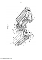
[0012] A figura 3 é uma vista em perspectiva do estado em que o cartucho de toner está ligado à unidade de processo;[0012] Figure 3 is a perspective view of the state in which the toner cartridge is connected to the process unit;
[0013] A figura 4 é uma vista em perspectiva do estado em que o cartucho de toner é removido da unidade de processo;[0013] Figure 4 is a perspective view of the state in which the toner cartridge is removed from the process unit;
[0014] A figura 5 é um diagrama de uma vista do lado mais próximo do cartucho de toner;[0014] Figure 5 is a diagram of a near-side view of the toner cartridge;
[0015] A figura 6 é uma vista em perspectiva que ilustra uma configuração do lado direito da unidade de processo e o cartucho de toner no estado em que o cartucho de toner está ligado à unidade de processo, (a) na figura 6 é um diagrama que ilustra um estado desbloqueado, e (b) na figura 6 é um diagrama que ilustra um estado bloqueado;[0015] Figure 6 is a perspective view illustrating a right side configuration of the process unit and the toner cartridge in the state where the toner cartridge is attached to the process unit, (a) in Figure 6 is a diagram illustrating an unlocked state, and (b) in Figure 6 is a diagram illustrating a locked state;
[0016] A figura 7 é um diagrama que ilustra uma visão interna de uma configuração no lado direito da unidade de processo e o cartucho de toner no estado em que o cartucho de toner está ligado à unidade de processo, (a) na figura 7 é um diagrama que ilustra o estado desbloqueado, (b) na figura 7 é um diagrama que ilustra um estado durante o bloqueio, e (C) na figura 7 é um diagrama que ilustra o estado bloqueado;[0016] Figure 7 is a diagram illustrating an inside view of a configuration on the right side of the process unit and the toner cartridge in the state where the toner cartridge is attached to the process unit, (a) in Figure 7 is a diagram illustrating the unlocked state, (b) in Figure 7 is a diagram illustrating a state during locking, and (C) in Figure 7 is a diagram illustrating the locked state;
[0017] A figura 8 é um diagrama que ilustra o estado durante o bloqueio, quando visto a partir do lado frontal do cartucho de toner;[0017] Figure 8 is a diagram illustrating the state during lockout, when viewed from the front side of the toner cartridge;
[0018] A figura 9 é um diagrama que ilustra uma configuração do lado esquerdo do cartucho de toner;[0018] Figure 9 is a diagram illustrating a configuration of the left side of the toner cartridge;
[0019] A figura 10 é uma vista em perspectiva do cartucho de toner em um estado em que uma entrada de resíduos de toner é aberta;[0019] Figure 10 is a perspective view of the toner cartridge in a state where a waste toner inlet is opened;
[0020] A figura 11 é uma vista em perspectiva do cartucho de toner em um estado em que a entrada de resíduos de toner está fechada;[0020] Figure 11 is a perspective view of the toner cartridge in a state where the waste toner inlet is closed;
[0021] A figura 12 é uma vista em perspectiva da parte relevante da unidade de processo em um estado em que uma saída de resíduo de toner está fechada;[0021] Figure 12 is a perspective view of the relevant part of the process unit in a state where a waste toner outlet is closed;
[0022] A figura 13 é uma vista em perspectiva da parte relevante da unidade de processo em um estado em que a saída de resíduos de toner é aberta;[0022] Figure 13 is a perspective view of the relevant part of the process unit in a state where the waste toner outlet is open;
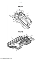
[0023] A figura 14 é uma vista em perspectiva do cartucho de toner que ilustra uma posição da disposição de um obturador de saída de toner de reposição;[0023] Figure 14 is a perspective view of the toner cartridge illustrating a position of the arrangement of a replacement toner outlet shutter;
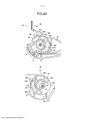
[0024] A figura 15 é uma vista em perspectiva da unidade de processo que ilustra uma posição da disposição de um elemento de ligação;[0024] Figure 15 is a perspective view of the process unit illustrating a position of the arrangement of a connecting element;
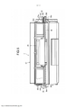
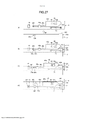
[0025] A figura 16 é uma vista em corte transversal do cartucho de toner, (a) na figura 16 é um diagrama que ilustra um estado em que a saída de toner de reposição é fechada, e (b) na figura 16 é um diagrama que ilustra um estado em que a saída de toner de reposição está aberta;[0025] Figure 16 is a cross-sectional view of the toner cartridge, (a) in figure 16 is a diagram illustrating a state where the replacement toner outlet is closed, and (b) in figure 16 is a diagram illustrating a state where the replacement toner outlet is open;
[0026] A figura 17 é uma vista lateral do cartucho de toner e a unidade de processo em um estado em que a saída de toner de reposição está fechada;[0026] Figure 17 is a side view of the toner cartridge and the process unit in a state where the replacement toner outlet is closed;
[0027] A figura 18 é uma vista lateral do cartucho de toner e a unidade de processo em um estado em que a saída de toner de reposição está aberta;[0027] Figure 18 is a side view of the toner cartridge and the process unit in a state where the replacement toner outlet is open;
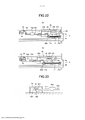
[0028] A figura 19 é uma vista em perspectiva que ilustra um estado acoplado de um elemento de operação, o obturador, e o elemento de ligação, quando o cartucho de toner é ligado a um dispositivo de revelação da unidade de processo;[0028] Figure 19 is a perspective view illustrating a coupled state of an operating element, the shutter, and the connecting element, when the toner cartridge is connected to a developing device of the process unit;
[0029] A figura 20 é uma vista lateral que ilustra um estado acoplado do elemento de operação, o obturador, e o elemento de ligação, quando o cartucho está ligado ao dispositivo de revelação da unidade de processo;[0029] Figure 20 is a side view illustrating a coupled state of the operating element, the shutter, and the connecting element, when the cartridge is connected to the developing device of the process unit;
[0030] A figura 21 é um diagrama que ilustra um estado em que um cartucho de processo, que inclui o cartucho de toner e a unidade de processo de uma forma integrada, está levantado;[0030] Fig. 21 is a diagram illustrating a state in which a process cartridge, which includes the toner cartridge and the process unit in an integrated manner, is raised;
[0031] A figura 22 é um diagrama que ilustra uma configuração de um mecanismo de abertura/ fechamento do obturador disposta à direita do dispositivo de revelação, (a) na figura 22 está um diagrama que ilustra um estado em que um corpo principal do obturador está posicionado numa posição de fechamento, e (b) na figura 22 está um diagrama que ilustra um estado em que o corpo principal do obturador está posicionado numa posição de abertura;[0031] Figure 22 is a diagram illustrating a configuration of a shutter opening/closing mechanism arranged to the right of the developing device, (a) in figure 22 is a diagram illustrating a state in which a main body of the shutter is positioned in a closed position, and (b) in figure 22 is a diagram illustrating a state in which the main body of the shutter is positioned in an open position;
[0032] A figura 23 é um diagrama que ilustra um mecanismo de bloqueio de um obturador de entrada de toner de reposição;[0032] Figure 23 is a diagram illustrating a locking mechanism of a replacement toner inlet shutter;
[0033] A figura 24 é um diagrama que ilustra uma configuração do lado direito do dispositivo de revelação e do cartucho de toner;[0033] Figure 24 is a diagram illustrating a configuration on the right side of the developer device and the toner cartridge;
[0034] A figura 25 é um diagrama que ilustra um estado em que a superfície de prensagem do cartucho de toner se encosta contra uma porção comprimida do corpo principal do obturador;[0034] Fig. 25 is a diagram illustrating a state in which the pressing surface of the toner cartridge abuts against a compressed portion of the main body of the shutter;
[0035] A figura 26 é um diagrama que ilustra um mecanismo de liberação de bloqueio do obturador de entrada de toner de reposição;[0035] Figure 26 is a diagram illustrating a replacement toner inlet shutter lock release mechanism;
[0036] A figura 27 é um diagrama que ilustra uma operação de abertura do obturador de entrada de toner de reposição;[0036] Figure 27 is a diagram illustrating an opening operation of the replacement toner input shutter;
[0037] A figura 28 é um diagrama que ilustra uma operação de fechamento do obturador de entrada de toner de reposição;[0037] Figure 28 is a diagram illustrating a replacement toner inlet shutter closing operation;
[0038] A figura 29 é uma vista em perspectiva que ilustra o lado direito do cartucho de processo;[0038] Figure 29 is a perspective view illustrating the right side of the process cartridge;
[0039] A figura 30 é uma vista em corte transversal do contorno das porções de suporte;[0039] Figure 30 is a cross-sectional view of the contour of the support portions;
[0040] A figura 31 é uma vista em perspectiva do elemento de operação;[0040] Figure 31 is a perspective view of the operating element;
[0041] A figura 32 é uma vista em perspectiva de uma segunda porção de engate;[0041] Figure 32 is a perspective view of a second engagement portion;
[0042] A figura 33 é um diagrama que ilustra um estado preliminarmente realizado, (a) na figura 33 ilustra uma vista lateral de uma primeira porção de engate, e (b) na figura 33 é uma vista lateral da segunda porção de engate;[0042] Figure 33 is a diagram illustrating a preliminary realized state, (a) in figure 33 illustrates a side view of a first engagement portion, and (b) in figure 33 is a side view of the second engagement portion;
[0043] A figura 34 é um diagrama que ilustra um estado bloqueado, (a) na figura 34 ilustra uma vista lateral da primeira porção de engate, e (b) na figura 34 é uma vista lateral da segunda porção de engate;[0043] Fig. 34 is a diagram illustrating a locked state, (a) Fig. 34 shows a side view of the first engaging portion, and (b) Fig. 34 is a side view of the second engaging portion;
[0044] A figura 35 é um diagrama que ilustra um estado de fixação pobre, (a) na figura 35 ilustra uma vista lateral da primeira porção de engate, e (b) na figura 35 é uma vista lateral da segunda porção de engate;[0044] Fig. 35 is a diagram illustrating a poor fastening state, (a) in Fig. 35 is a side view of the first engaging portion, and (b) in Fig. 35 is a side view of the second engaging portion;
[0045] A figura 36 é um diagrama que ilustra uma relação de posição entre as porções de engate e as porções de suporte, em um estado de fixação normal, (a) na figura 36 é uma vista em corte transversal do estado preliminarmente realizado, e (b) na figura 36 é uma vista em corte transversal do estado bloqueado, após uma operação do elemento de operação;[0045] Figure 36 is a diagram illustrating a positional relationship between the hook portions and the support portions, in a normal fastening state, (a) in figure 36 is a cross-sectional view of the preliminarily realized state, and (b) in figure 36 is a cross-sectional view of the locked state after an operation of the operating element;
[0046] A figura 37 é um diagrama que ilustra uma relação de posição entre as porções de engate e as porções de suporte em estado de fixação pobre, (a) na figura 37 é uma vista em corte transversal do estado preliminarmente realizado, e (b) na figura 37 é uma vista em corte transversal do estado bloqueado, após uma operação do elemento de operação;[0046] Fig. 37 is a diagram illustrating a positional relationship between the hook portions and the support portions in a poor fixing state, (a) in Fig. 37 is a cross-sectional view of the preliminarily realized state, and ( b) in figure 37 is a cross-sectional view of the locked state after an operation of the operating element;
[0047] A figura 38 é uma vista em perspectiva que ilustra uma segunda concretização do elemento de operação;[0047] Figure 38 is a perspective view illustrating a second embodiment of the operating element;
[0048] A figura 39 é uma vista em perspectiva da segunda concretização da segunda porção de engate;[0048] Figure 39 is a perspective view of the second embodiment of the second engaging portion;
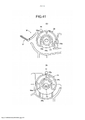
[0049] A figura 40 é um diagrama que ilustra o estado bloqueado de acordo com a segunda concretização, (a) na figura 40 é uma vista lateral da primeira porção de engate, e (b) na figura 40 é uma vista lateral da segunda porção de engate;[0049] Fig. 40 is a diagram illustrating the locked state according to the second embodiment, (a) in Fig. 40 is a side view of the first engaging portion, and (b) in Fig. 40 is a side view of the second coupling portion;
[0050] A figura 41 é um diagrama que ilustra o estado preliminarmente realizado de acordo com a segunda concretização, (a) na figura 41 é uma vista lateral da primeira porção de engate, e (b) na figura 41 é uma vista lateral da segunda porção de engate;[0050] Figure 41 is a diagram illustrating the preliminary state realized according to the second embodiment, (a) in figure 41 is a side view of the first engaging portion, and (b) in figure 41 is a side view of the second engagement portion;
[0051] A figura 42 é um diagrama de configuração geral de um aparelho de formação de imagem colorida do tipo de transferência indireta;[0051] Fig. 42 is a general configuration diagram of an indirect transfer type color imaging apparatus;
[0052] A figura 43 é um diagrama de configuração geral de um aparelho de formação de imagem colorida de transferência direta; e[0052] Fig. 43 is a general configuration diagram of a direct transfer color imaging apparatus; and
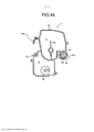
[0053] A figura 44 é uma vista em corte transversal do cartucho de toner com um dispositivo de preensão. Descrição de Concretizações[0053] Figure 44 is a cross-sectional view of the toner cartridge with a gripping device. Description of Achievements
[0054] É dada abaixo a explicação da presente invenção, com referência aos desenhos anexos. Aqui, nos desenhos utilizados para explicar a presente invenção, em relação aos elementos constitutivos, tais como elementos ou componentes constitutivos que possuem a mesma função ou a mesma forma, os mesmos numerais de referência são usados em uma extensão máxima de distinção e a explicação não será repetida após fornecida uma vez.[0054] The explanation of the present invention is given below with reference to the accompanying drawings. Here, in the drawings used to explain the present invention, with respect to constitutive elements, such as constitutive elements or components that have the same function or the same form, the same reference numerals are used to the fullest extent of distinction and the explanation does not will be repeated after provided once.
[0055] A figura 1 é um diagrama de configuração geral que ilustra uma concretização de um aparelho de formação de imagem. Em primeiro lugar, explicado abaixo com referência à figura 1 está uma configuração e operações gerais do aparelho de formação de imagem.[0055] Figure 1 is a general configuration diagram illustrating an embodiment of an imaging apparatus. First, explained below with reference to Figure 1 is a general configuration and operations of the imaging apparatus.
[0056] O aparelho de formação de imagem ilustrado na figura 1 é um aparelho de formação de imagem monocromática. Em um corpo principal do aparelho (um corpo principal de aparelhos de formação de imagem) 100, uma unidade de processo de um funcionando como uma unidade de formação de imagens é montada de forma destacável. A unidade de processo 1 inclui um elemento fotossensível 2 que funciona como um transportador de imagem para transportar uma imagem na superfície do mesmo; um rolo de carregamento 3 que funciona como uma unidade de carga para o carregamento da superfície do elemento fotossensível 2; 4 um dispositivo de revelação que funciona como uma unidade de revelação para a conversão de uma imagem latente formada no elemento fotossensível 2 em uma imagem visível; e uma lâmina de limpeza 5 que funciona como uma unidade de limpeza para limpeza da superfície exterior do elemento fotossensível 2. Além disso, em uma posição oposta ao elemento fotossensível 2, um arranjo principal LED 6 (LED significa diodos emissores de luz) é disposto que funciona como uma unidade de exposição para expor a superfície exterior do elemento fotossensível 2 à luz.[0056] The imaging apparatus illustrated in Figure 1 is a monochromatic imaging apparatus. In an apparatus main body (an imaging apparatus main body) 100, a process unit of one functioning as an imaging unit is detachably mounted. The
[0057] Além disso, um cartucho de toner 7, que serve como um recipiente de toner é unido de forma removível à superfície superior (uma porção de montagem) do dispositivo de revelação 4 da unidade de processo 1. O cartucho de toner 7 tem um corpo de recipiente 22 que inclui uma unidade de contendo toner 8 para alojar um toner, que é um toner a ser fornecido para o dispositivo de revelação 4. Além disso, na presente concretização, o cartucho de toner 7 também inclui, de uma maneira integrada, uma unidade de coleta de toner 9 que coleta o toner removido pela lâmina de limpeza 5 (ou seja, coleta resíduos de toner).[0057] In addition, a
[0058] Enquanto isso, o aparelho de formação de imagem inclui também um dispositivo de transferência 10 que transfere uma imagem para uma folha de papel que serve como um meio de gravação; um dispositivo de alimentação de papel 11 que alimenta folhas de papel; um dispositivo de fixação 12 que fixa uma imagem, a qual foi transferida para uma folha de papel, na folha de papel; e um dispositivo de descarga de papel 13 que descarrega uma folha de papel para o exterior do aparelho de formação de imagem.[0058] Meanwhile, the image forming apparatus also includes a
[0059] O dispositivo de transferência 10 inclui um rolo de transferência 14 que funciona como um elemento de transferência. No estado em que a unidade de processo 1 é montada no corpo principal de aparelho 100, o rolo de transferência 14 encosta-se contra o elemento fotossensível 2. Como um resultado, um contato de transferência é formado na porção de encosto entre o rolo de transferência 14 e o elemento fotossensível 2. Além disso, o rolo de transferência 14 é ligado a uma fonte de energia (não ilustrada) e é aplicada uma tensão de corrente contínua (DC) predeterminada ou uma tensão de corrente alternada (AC) predeterminada.[0059] The
[0060] O dispositivo de alimentação de papel 11 inclui um cassete de alimentação de papel 15 em que folhas de papel P estão alojadas, e um rolo de alimentação de papel 16 que alimenta as folhas de papel P alojadas no cassete de alimentação de papel 15. No lado a jusante na direção de transporte de papel do rolo de alimentação de papel 16, um par de rolos de registro 17 é disposto que serve como um par de rolos de temporização para cronometrar o tempo de transporte e, consequentemente, transportar uma folha de papel para um encosto de transferência secundário. Entretanto, exemplos da folha de papel P incluem uma folha de cartão, um cartão, uma etiqueta, uma folha de papel normal, uma folha de papel fino, uma folha de papel revestida (tal como uma folha de papel de revestimento ou uma folha de papel de arte), ou uma folha de papel tracejada. Além disso, na medida em que mídias de gravação outras do que as folhas de papel estão relacionadas, é possível utilizar folhas de OHP ou películas de OHP (OHP significa retroprojetor).[0060] The
[0061] O dispositivo de fixação 12 inclui um rolo de fixação 18 que funciona como um elemento de fixação, e um rolo de pressão 19, que funciona como um membro de pressão. O rolo de fixação 18 é aquecida por uma fonte de calor tal como um aquecedor (não ilustrado). O rolo de pressão 19 é pressurizado para o rolo de fixação 18 e encosta-se contra o rolo de fixação 18. Como resultado, uma um encosto de fixação é formado no local de encosto.[0061] The
[0062] O dispositivo de descarga de papel 13 inclui um par de rolos de descarga de papel 20. Uma folha de papel que é descarregada para o exterior do aparelho de formação de imagem pelos rolos de descarga de papel 20 é empilhada sobre uma bandeja de recepção 21 que é formada fazendo uma depressão na superfície superior do corpo de aparelho principal 100.[0062] The
[0063] Em seguida, explicada a seguir com referência à figura 1 está uma operação de formação de imagem realizada no aparelho de formação de imagem de acordo com a presente concretização.[0063] Next, explained below with reference to Figure 1 is an image forming operation performed on the image forming apparatus according to the present embodiment.
[0064] Uma vez que a operação de formação de imagem é iniciada, o elemento fotossensível 2 é acionado de forma rotativa, e a superfície do elemento fotossensível 2 é carregada uniformemente com uma polaridade predeterminada. Em seguida, com base na informação de imagem recebida a partir de um dispositivo de leitura (não ilustrado) ou a um computador (não ilustrado), a superfície carregada do elemento fotossensível 2 é exposta à luz a partir do arranjo principal de LED 6. Como resultado, uma imagem latente eletrostática é formada sobre a superfície carregada do elemento fotossensível 2. Em seguida, o dispositivo de revelação 4 fornece um toner para a imagem latente eletrostática formada no elemento fotossensível 2. Como resultado, a imagem latente eletrostática é revelada como uma imagem de toner (isto é, convertida numa imagem visível).[0064] Once the imaging operation is started, the
[0065] Enquanto isso, uma vez que a operação de imagem é iniciada, os rolos de alimentação de papel 16 começam o acionamento rotativo de modo que uma folha de papel P é alimentada a partir do cassete de alimentação de papel 15. No entanto, nos rolos de registro 17, a folha de papel P é temporariamente parada de ser transportada adiante. Em seguida, num tempo predeterminado, os rolos de registo 17 começam o acionamento rotativo e transportam a folha de papel P para o contato de transferência em sincronização com o tempo em que uma imagem de toner formada no elemento fotossensível 2 atinge o contato de transferência.[0065] Meanwhile, once the imaging operation starts, the
[0066] Nessa altura, para o rolo de transferência 14, uma tensão de transferência é aplicada que tem a polaridade oposta à polaridade do carregamento de toner para a imagem de toner formada no elemento fotossensível 2. Como um resultado, um campo elétrico de transferência é formado na localização de transferência. Devido ao campo elétrico de transferência, a imagem de toner formada no elemento fotossensível 2 é transferida para a folha de papel P. Em seguida, o resíduo de toner que não é transferido para a folha de papel P e que permanece no elemento fotossensível 2 é removido pela lâmina de limpeza 5 e é coletado pela unidade de coleta de toner 9 no cartucho de toner 7.[0066] At that time, to the
[0067] A folha de papel P sobre a qual a imagem de toner foi transferida, em seguida, é transmitida para o dispositivo de fixação 12, e passa através do ponto de aperto de fixação formado entre o rolo de fixação 18 e o rolo de pressão 19. Como resultado, a folha de papel P se torna aquecida e a pressurizada, e a imagem de toner se fixa à folha de papel P. Em seguida, a folha de papel P é descarregada pelos rolos de descarga de papel 20 para o exterior do aparelho de formação de imagem e é empilhado na bandeja de recepção 21.[0067] The sheet of paper P onto which the toner image has been transferred is then transmitted to the
[0068] A figura 2 é um diagrama que ilustra um método de fixar e remover a unidade de processo.[0068] Figure 2 is a diagram illustrating a method of attaching and removing the process unit.
[0069] Tal como ilustrado na figura 2, na presente concretização, uma tampa 101, ligada à porção frontal do corpo de aparelho principal 100 pode ser fechada e pode ser aberta de natureza. Quando a tampa 101 é mantida aberta, o arranjo principal LED 6 torna-se capaz de retrair para cima através de um mecanismo de ligação (não ilustrado). Com uma tal configuração, quando a tampa 101 é mantida aberta, a unidade de processo 1 pode ser removida a partir do lado frontal do aparelho de formação de imagem (isto é, do lado voltado para a direção de viagem de uma folha de papel descarregada P; ou a partir do lado direito com referência à figura 2), evitando a interferência com o arranjo principal LED 6. Naquele tempo, no estado em que o cartucho de toner 7 está ligado à unidade de processo 1, o cartucho de toner 7 e a unidade de processo 1 podem ser removidos como um cartucho de processo integrado a partir do lado frontal do corpo de aparelho principal 100. Por outro lado, independentemente do fato de a unidade de processo 1 estar ligada ao corpo de aparelho principal 100, ou é removida a partir do corpo de aparelho principal 100, o cartucho de toner 7 pode ser ligado a ou removido da unidade de processo 1.[0069] As illustrated in Figure 2, in the present embodiment, a
[0070] A figura 3 é uma vista em perspectiva de um estado em que o cartucho de toner é ligado à unidade de processo. A figura 4 é uma vista em perspectiva de um estado em que o cartucho de toner é removido da unidade de processo.[0070] Figure 3 is a perspective view of a state in which the toner cartridge is connected to the process unit. Figure 4 is a perspective view of a state in which the toner cartridge is removed from the process unit.
[0071] Com referência à figura 3, a direção indicada por uma seta A1 representa a direção de fixação no tempo da fixação da unidade de processo 1 e o cartucho de toner 7 para o corpo de aparelho principal 100. Por outro lado, a direção indicada por uma seta A2 representa a direção de remoção no tempo da remoção da unidade de processo 1 e o cartucho de toner 7 a partir do corpo de aparelho principal 100.[0071] With reference to figure 3, the direction indicated by an arrow A1 represents the clamping direction in time from clamping
[0072] Na explicação seguinte, no cartucho de toner 7 e na unidade de processo 1, o lado frontal da direção de fixação A1 (ou o lado frontal de uma direção de fixação B1) é referido como o lado mais distante, e o lado traseiro oposto ao lado frontal é referido como o lado mais próximo. Além disso, o lado direito e o lado esquerdo, são definidos enquanto voltados para o lado frontal da direção de fixação A1 (ou a direção de fixação B1).[0072] In the following explanation, on
[0073] No lado mais próximo na direção de fixação do cartucho de toner 7, um dispositivo de preensão 25 é disposto que pode ser agarrado por um operador quando da fixação do cartucho de toner 7 a ou remoção do cartucho 7 a partir do corpo de aparelho principal 100 ou da unidade de processo 1. O dispositivo de preensão 25 é fixado de um modo articulado em relação a um eixo 35 (ver figura 4) que é uma haste colunar disposta em paralelo à direção longitudinal do corpo de recipiente 22. No momento da remoção do cartucho de toner 7 e da unidade de processo 1 do corpo de aparelho principal 100, ou no momento da remoção do cartucho de toner 7 da unidade de processo 1; como ilustrado na figura 4, o dispositivo de preensão 25 é articulado em direção ao lado próximo, de forma que se torna possível agarrar o dispositivo de preensão 25. Por outro lado, depois do cartucho de toner 7 e da unidade de processo 1 serem fixados ao corpo de aparelho principal 100; como ilustrado na figura 7, o dispositivo de preensão 25 é articulado em direção ao lado mais distante para que se torne possível manter o dispositivo de preensão 25 em um estado alojados. Além disso, o centro de articulação do dispositivo de preensão 25 (isto é, o eixo 35) é definido para ser localizado mais abaixo do que um ponto de gravidade G do dispositivo de preensão 25 (ver (a) e (b) na figura 16). Por isso, no estado fixado da unidade de processo 1, como ilustrado na figura 2, mesmo se o operador se esquecer de girar o dispositivo de preensão 25 para o lado oposto, a tampa 101 pode ser articulada a partir de baixo até que ela toque o dispositivo de preensão 25 e, em seguida, o dispositivo de preensão 25 pode ser articulado em conjunto para mantê-lo no estado alojado.[0073] On the side closest to the
[0074] Nota-se que o dispositivo de preensão acima mencionado pode ser não articulável a, mas pode ser fixado à tampa 101, desde que o dispositivo de preensão tenha um tamanho tal que a tampa 101 pode ser fechada sem que o dispositivo de preensão interfira com a tampa. A figura 44 ilustra um dispositivo de preensão 250 em outra concretização. O dispositivo de preensão 250 está disposto no centro, na direção longitudinal do corpo de recipiente e acima do eixo 35. Também nesta estrutura, o operador pode transportar o cartucho de toner 7 e a unidade de processo 1, tal como um cartucho de processo integrado de uma forma de retenção semelhante à ilustrada na figura 21.[0074] It is noted that the aforementioned gripping device can be non-hingable to, but can be fixed to the
[0075] Explicado a seguir, com referência às figuras 3 a 16, encontra-se uma explicação mais detalhada sobre a configuração do cartucho de toner 7 e da unidade de processo 1.[0075] Explained below, with reference to figures 3 to 16, is a more detailed explanation of the configuration of
[0076] Tal como ilustrado na figura 4, em um lado direito 22a do corpo de recipiente 22, um elemento de operação 26 que é articulável é disposto. O elemento de operação 26 está fixo à extremidade direita do eixo 35, e gira juntamente com o eixo 35. A fim de fazer o eixo 35 pode rodar em relação ao corpo do recipiente 22, o eixo 35 é suportado de modo articulado com rolamentos 27a e 27b (ver figura 5) em ambas as extremidades do corpo de recipiente 22.[0076] As illustrated in figure 4, on a
[0077] Tal como ilustrado nas figuras 6 e 7, o elemento de operação 26 inclui, de uma maneira integrada, uma alavanca 57 e uma primeira porção de engate 58 que gira juntamente com o eixo 35. A alavanca 57 inclui uma porção de fixação 26a à qual o eixo 35 é fixo; uma porção de extensão 26b, que se estende a partir da porção de fixação 26a, numa direção perpendicular à direção de eixo do eixo 35; e uma porção de placa 26c que, quando vista a partir da direção de eixo do eixo 35, se curva a partir da porção de extensão 26b e se estende ainda mais. Em outras palavras, a porção de placa 26c se estende com um ângulo em relação à direção radial a partir do centro do eixo 35.[0077] As illustrated in Figures 6 and 7, the operating
[0078] Tal como ilustrado na figura 14, a primeira porção de engate 58 inclui, de uma forma integrada e em uma extremidade do eixo 35, uma porção de placa de base 58a, que é em forma de disco e se estende numa direção perpendicular à direção de eixo do eixo 35, e uma porção erguida 58b, que é erguida a partir da porção de placa de base 58a na direção de eixo do eixo 35. Conforme ilustrado na figura 20, a porção erguida 58b se estende na direção circunferencial da porção de placa de base 58a e tem uma estrutura de parede dupla com ambas as suas extremidades na direção circunferencial sendo fechada. A porção erguida 58b tem uma parede exterior 581 radialmente para fora e tem uma parede interior 582 radialmente para dentro. A porção entre as duas extremidades na direção circunferencial da porção erguida 58b é aberta para uma direção perpendicular à direção do eixo, e a periferia interior da parede interior 582 forma uma primeira superfície de engate 58c que tem uma borda em forma de U quando vista a partir da direção do eixo. O elemento de operação 26 é fixado a uma extremidade do eixo 35 com as partes superiores da porção erguida 58b da primeira porção de engate 58 apontando para fora. No momento da fixação do cartucho de toner 7 à unidade de processo 1, uma porção de suporte 54 (ver figura 29), que é uma saliência e dispostos sobre um lado direito 1a da unidade de processo 1, engata com a primeira envolvente 58c superfície. Aqui, desde que a primeira porção de engate 58 seja capaz de se articular em conjunto com a alavanca 57, ela pode ter uma configuração arbitrária. Assim, para além da configuração explicada acima, em que a alavanca 57 e a primeira porção de engate 58 são formados de um modo integrado, também é possível tratar a alavanca 57 e a primeira porção de engate 58 como elementos separados e fixá-los ao eixo 35 separadamente.[0078] As illustrated in Figure 14, the
[0079] Assim, o cartucho de toner 7 pode ser fixado à unidade de processo 1, ao articular o elemento de operação 26. Mais particularmente, como se ilustra em (a) da figura 6, na parte superior do lado direito da porção de placa 26c do elemento de operação 26, uma porção de bloqueio 26c1 é formada como uma saliência que pode engatar com uma porção de engate 1c que é formada como uma porção de engate do lado da porção de montagem do lado direito lado 1a da unidade de processo 1. O lado 1a é o da superfície de parede interior oposto ao lado direito do cartucho de toner 7.[0079] Thus, the
[0080] Em outras palavras, a porção de engate 1c é formada na superfície de parede interna mencionada acima e serve como uma ranhura de guia na qual a saliência da porção de bloqueio 26c1 pode entrar. A porção de engate 1c inclui uma porção aberta 1c1 de onde a ranhura começa e vai para o lado direito 1a a partir do lado vertical próximo do lado direito 1a; inclui uma porção curva 1c2 em que a ranhura se curva a meio caminho; e uma porção aberta 1c3 a partir da qual a ranhura escapa para o lado horizontal superior do lado direito 1a. Além disso, das duas superfícies laterais da ranhura da porção de engate 1c, quando vista a partir da direção do eixo do eixo 35, a superfície do lado que está mais distante do centro do eixo e que varia a partir da porção aberta 1c1 para a porção curva 1c2 serve como uma superfície de deslizamento 1c4 em que a porção de bloqueio 26c1 move-se de uma maneira deslizante. Além disso, uma superfície de engate 1c5 está presente, que é ligada à superfície de deslizamento 1c4, que se estende na direção vertical a partir da porção curva 1c2 para a porção aberta 1c3, e com a qual a porção de bloqueio 26c1 se engata.[0080] In other words, the
[0081] A seguir, é dada a explicação de uma sequência de operações do elemento de operação 26 no estado em que o cartucho de toner 7 está fixado à unidade de processo 1.[0081] The following is an explanation of a sequence of operations of the
[0082] Em primeiro lugar, tal como ilustrado na figura 6 (a) e figura 7 (a), no estado em que o cartucho de toner 7 é fixado a, mas ainda não travado com a unidade de processo 1, o operador mantém a parte superior e a parte inferior da porção de placa 26c do elemento de operação 26 com os dedos ou pressiona a porção de placa 26c a partir de baixo para aplicar uma força de compressão ao elemento de operação 26 e gira o elemento de operação 26, para pressioná- lo para o lado distante. Como resultado, a porção de bloqueio 26c1 alcança a porção aberta 1c1 no lado vertical próximo da porção de engate 1c. Além disso, se uma força de compressão é aplicada à porção de placa 26c do elemento de operação 26 para rodar o mesmo para o lado oposto; em seguida, como ilustrado na figura 7 (b), a porção de bloqueio 26c1 se move ao contatar com (deslizante em) a superfície de deslizamento 1c4. Devido ao contato entre a porção de bloqueio 26c1 e a superfície de deslizamento 1c4, uma força de travagem J é aplicada na direção oposta a uma força de compressão X aplicada ao elemento de operação 26 (isto é, a força de travagem J é aplicada contra a força de compressão X). Aqui, a porção de placa 26c é formada com uma única placa de resina tal como poliestireno, que é deformável elasticamente em uma extensão. Assim, como ilustrado na figura 8, a porção de placa 26c é pressionada de uma forma deformada para o lado distante da porção de bloqueio 26c1 como o ponto de articulação. Então, como ilustrado na figura 7 (C), uma vez que a porção de bloqueio 26c1 alcança a porção curva 1c2, existe um fim para o estado de deslizamento da porção de bloqueio 26c1 com relação à superfície de deslizamento 1c4, e a porção de bloqueio 26c1 se encosta contra a superfície de engate 1c5. Desta forma, o estado em que a porção de bloqueio 26c1 permanece encostada contra a superfície envolvente 1c5 é o estado bloqueado. Além disso, no estado bloqueado, a porção de placa 26c é liberada do estado elasticamente deformado e retorna à forma original. Além disso, a porção de placa 26c tem uma orientação tal que a porção de bloqueio 26c1 está posicionada para se encostar contra a superfície de engate 1c5. Com isso, mesmo que uma força inesperada seja aplicada, deste modo fazendo com que a porção de placa 26c do elemento de operação 26 gire para o lado próximo, a porção de placa 26c não sofre deformação a menos que uma força substancialmente grande seja aplicada. Assim, a porção de bloqueio 26c1 também vai além da superfície de engate 1c5.[0082] First, as illustrated in figure 6(a) and figure 7(a), in the state where the
[0083] Por outro lado, se o operador pressiona a porção de placa 26c a partir de cima, usando os dedos e gira o elemento de operação 26 para o lado próximo, em seguida, a porção de placa 26c sofre uma deformação elástica da porção de bloqueio 26c1 como o ponto de articulação e na direção oposta ao caso em que é pressionada para o lado distante como descrito acima. Em seguida, o engate entre a porção de bloqueio 26c1 e a porção de engate 1c é liberado, e o estado é comutado para um estado de bloqueio liberado.[0083] On the other hand, if the operator presses the
[0084] Enquanto isso, como ilustrado na figura 4, no lado direito 22a do corpo do recipiente 22, uma projeção de posicionamento 29 sob a forma de uma saliência cilíndrica é disposta com a finalidade de determinar a posição do cartucho de toner 7 em relação à unidade de processo 1. Numa maneira idêntica, em um lado esquerdo 22b do corpo de recipiente 22, tal como ilustrado na figura 10, uma projeção de posicionamento 31 sob a forma de uma saliência tendo uma superfície transversal em forma meia-lua é disposta com a finalidade de determinar a posição do cartucho de toner 7 em relação à unidade de processo 1. De modo correspondente, no lado direito 1a e no lado esquerdo 1b da unidade de processo 1, porções de guia tipo ranhura 30 e 32 são formadas (ver a figura 4), respectivamente, de tal maneira que as superfícies curvas das projeções de posicionamento 29 e 31se encostam contra as porções de guia 30 e 32.[0084] Meanwhile, as illustrated in figure 4, on the
[0085] Tal como ilustrado na figura 10, no lado esquerdo 22b do corpo de recipiente 22, uma segunda porção de engate 34 está ligado de um modo articulado. De uma forma idêntica à primeira porção de engate 58, a segunda porção de engate 34 inclui, de uma maneira integrada, uma porção de placa de base 34a, que é em forma de disco e se estende numa direção perpendicular à direção de eixo do eixo 35, e um porção erguida 34b, que é erguida a partir da porção de placa de base 34a na direção de eixo do eixo 35. A porção de placa de base 34a é fixada à outra extremidade do eixo 35. A porção erguida 34b se estende na direção circunferencial da porção de placa de base 34a e tem uma estrutura de parede dupla com ambas as suas extremidades na direção circunferencial sendo fechada. Assim, a porção erguida 34b inclui uma parede exterior 341 radialmente no exterior e uma parede interior 342 radialmente no interior. A porção entre as duas extremidades na direção circunferencial da porção erguida 34b é aberta para uma direção perpendicular à direção de eixo, e a periferia interior da parede interior 342 forma uma segunda superfície de engate 34c que tem uma borda em forma de U quando vista a partir da direção do eixo. No momento de fixação do cartucho de toner 7 à unidade de processo 1, uma porção de suporte 33 (ver figura 4), que é uma saliência e formada no lado esquerdo 1b da unidade de processo 1, se engata com a segunda superfície de engate 34c.[0085] As illustrated in Figure 10, on the
[0086] Na presente concretização, a segunda porção de engate 4 é acoplada com o eixo 35 (ver figura 4) ao qual o elemento de operação 26 é também acoplado. Assim, quando o elemento de operação 26 é articulado, quer na direção para frente ou para trás, a segunda porção de engate 34 também gira tanto na direção para frente ou para trás em conjunto. Além disso, na presente concretização, o dispositivo de preensão 25 também é ligado ao eixo 35 que é acoplado ao primeiro elemento de engate 34 e ao elemento de operação 26. No entanto, o dispositivo de preensão 25 é configurado para ser articulável de forma independente do eixo 35, e é configurado para não operar em conjunto com o elemento de operação 26.[0086] In the present embodiment, the
[0087] Tal como ilustrado na figura 5, entre o eixo 35 e o corpo do recipiente 22, uma mola helicoidal de torção 28 é colocada. Devido à mola helicoidal de torção 28, não só o eixo 35 é pressionado na direção dos ponteiros do relógio com referência à figura 9, mas também o elemento de operação 26 (a primeira porção de engate 58) e a segunda porção de engate 34 que está acoplada com o eixo 35 são também tensionados no sentido horário com referência à figura 9. Além disso, com a utilização de um batente que resiste a tensão da mola helicoidal de torção 28, a primeira porção de engate 58 e a segunda porção de engate 34 são mantidas em orientações específicas. Mais particularmente, num estado natural em que nenhuma força externa está sendo aplicada ao elemento de operação 26, a primeira porção de engate 58 e a segunda porção de engate 34 são mantidas de tal maneira que uma abertura entre ambas as extremidades das porções erguidas 58b e 34b, respectivamente, estão voltadas em uma direção obliquamente para baixo. Na presente concretização, tal como ilustrado na figura 9, desde que a direção da abertura da segunda porção de engate 34 seja relacionada; quando o cartucho de toner 7 é montado sobre uma superfície de montagem Z, a periferia interna da porção erguida 58b na vizinhança da abertura é voltada para uma direção inclinada para o lado distante por 30° com relação a uma linha vertical V que corresponde ao plano horizontal. Tal como ilustrado na figura 14, a direção da abertura da primeira porção de engate 58 também é idêntica à direção da abertura da segunda porção de engate 34, e é inclinada para o lado oposto por 30° com relação à linha vertical V.[0087] As illustrated in figure 5, between the
[0088] Além disso, como ilustrado na figura 10, no lado esquerdo 22b do corpo de recipiente 22, uma entrada de resíduos de toner 36 sob a forma de um furo em forma de quadrado é formada com a finalidade de descarregar o resíduo de toner para o interior (para a unidade de coleta de toner 9). A entrada de resíduos de toner 36 é formada numa parte de depressão em forma de arco 22d que é formada sob a projeção de posicionamento 31; e tem o furo no sentido ascendente. Em torno da entrada de resíduos de toner 36 é colada uma vedação 36a que é formada utilizando um material esponjoso. No lado superior da vedação 36a, um obturador de entrada de resíduos de toner 37 é disposto (ver figura 11) de uma forma articulável, de modo a deslizar sobre a superfície superior da vedação 36a.[0088] Furthermore, as illustrated in Figure 10, on the
[0089] O obturador de entrada de resíduos de toner 37 é curvo para ser capaz de girar ao longo da porção de depressão em forma de arco 22d. Além disso, no estado em que o cartucho de toner 7 é mantido sozinho, o obturador de entrada de resíduos de toner 37 é tensionado por um elemento tendencioso 37a, que é uma mola helicoidal de torção, na direção de rotação, em que a entrada de resíduo de toner 36 permanece sempre fechada. O elemento tendencioso 37a é colocado entre o obturador de entrada de resíduo de toner 37 e o cartucho de toner 7. O eixo de rotação do obturador de entrada de resíduos de toner 37 é inserido na mola helicoidal de torção (a elemento tendencioso 37). Quando o obturador de entrada de resíduos de toner 37 gira, torna-se possível alternar entre um estado aberto (o estado ilustrado na figura 10) em que a entrada de resíduos de toner 36 está aberta e um estado fechado (o estado ilustrado na figura 11) em que a entrada de resíduos de toner 36 está fechada.[0089] The waste
[0090] Tal como ilustrado na figura 12, perto do lado esquerdo 1b da unidade de processo 1, um percurso de transporte de resíduo de toner 39 tendo uma forma tubular, é disposto de forma saliente para o interior. No final do percurso de transporte de resíduo de toner 39 é disposta uma saída de resíduos de toner 38, por meio da qual o resíduo de toner é eliminado e que tem uma abertura na direção descendente. Além disso, para a periferia exterior da extremidade do percurso de transporte de resíduos de toner 39, um obturador de saída de resíduos de toner 40 é fixado com a finalidade de abrir e fechar a saída de resíduos de toner 38. O obturador de saída de resíduos de toner 40 é configurado para ser capaz de girar em torno do centro do eixo. Assim, é possível mudar entre um estado aberto (estado ilustrado na figura 13) no qual a saída de resíduos de toner 38 é aberta e um estado fechado (um estado ilustrado na figura 12) no qual a saída de resíduos de toner 38 é fechada.[0090] As illustrated in Figure 12, near the
[0091] O obturador de entrada de resíduos de toner 37 é tensionado pelo elemento tendencioso 37a (ver figura 10), que é feito de uma mola helicoidal de torção, na direção de fechamento da entrada de resíduos de toner 36; enquanto o obturador de saída de resíduos de toner 40 é tensionaod por um elemento tendencioso 40a (ver figura 12), que é feito de uma mola helicoidal de torção, na direção do fechamento da saída de resíduos de toner 38. Além disso, no obturador de saída de resíduos de toner 40, uma porção convexa 41 é formada, que o obturador de entrada de resíduos de toner 37 contata no momento da fixação do cartucho de toner 7 à unidade de processo 1. Uma vez que o obturador de entrada de resíduos de toner 37 contata a porção convexa 41; o obturador de entrada de resíduos de toner 37 gira na direção em que a entrada de resíduos toner 36 abre (na direção de uma seta ilustrada na figura 10), enquanto o obturador de saída de resíduos de toner 40 gira na direção em que a saída de resíduos de toner 38 é aberta (na direção da seta ilustrada na figura 13). Em seguida, no estado em que o cartucho de toner 7 é fixado à unidade de processo 1, a entrada de resíduos de toner 36 no estado aberto e a saída de resíduos de toner 38 no estado aberto são posicionadas opostas entre si. Assim, nesse estado, entrada de resíduos de toner 36 e a saída de resíduos de toner 38 estão em comunicação entre si. Como resultado, o resíduo de toner removido a partir da superfície exterior do elemento fotossensível 2 pode ser descarregado no cartucho de toner 7 (isto é, na unidade de coleta de toner 9).[0091] The waste
[0092] Em contraste, no estado em que o cartucho de toner 7 é removido da unidade de processo 1, o contato entre o obturador de entrada de resíduos de toner 37 e a porção convexa 41 é liberado, e obturador de entrada de resíduos de toner 37 e o obturador de saída de resíduos de toner 40 giram nas direções de tensão dos respectivos elementos tendenciosos (nos sentidos das setas ilustradas nas figuras 11 e 12, respectivamente). Como resultado, a entrada de resíduos de toner 36 e a saída de resíduos de toner 38 são fechadas, impedindo assim que qualquer vazamento de toner ocorra através da entrada de resíduos de toner 36 e da saída de resíduos de toner 38.[0092] In contrast, in the state where the
[0093] Enquanto isso, como ilustrado na figura 14, sobre uma superfície curva presente perto do lado direito 22a lateral do corpo de recipiente 22, uma saída de toner de reposição 42 sob a forma de um furo de forma quadrada é formada com a finalidade de descarregar o toner que está contido no recipiente de toner 8. A saída de toner de reposição 42 tem o furo no sentido descendente. Além disso, por baixo da saída de toner de reposição 42, um obturador de saída de toner de reposição 43 é disposto ao longo da superfície curva (superfície em forma de arco) da saída de toner de reposição 42. O obturador de saída de toner de reposição 43 pode ser usado na abertura e fechamento da saída de toner de reposição 42. O obturador de saída de toner de reposição 43 é disposto de um modo articulado ao longo da superfície curva (superfície do arco semelhante) da saída de toner de reposição 42 e de um modo concêntrico com o eixo cilíndrico da projeção de posicionamento 29 que é uma saliência cilíndrica.[0093] Meanwhile, as illustrated in figure 14, on a curved surface present near the
[0094] O obturador de saída de toner de reposição 43 inclui uma saliência 43b que se projeta na direção do eixo de rotação do obturador de saída de toner de reposição 43. Tal como ilustrado na figura 14, uma mola helicoidal de torção 43c, que serve como um elemento tendencioso, é disposta entre o obturador de saída de toner de reposição 43 e o lado direito 22a, que serve como um elemento de tampa para esconder uma engrenagem. Além disso, na porção de extremidade 43c da mola helicoidal de torção é disposta uma porção de gancho que é engatada à saliência 43b. Assim, a obturador de saída de toner de reposição 43 é tensionado pela mola helicoidal de torção 43c na direção de fechamento da saída de toner de reposição 42.[0094] The replacement
[0095] Tal como ilustrado na figura 15, perto do lado direito 1a do dispositivo de revelação 4 da unidade de processo 1, uma entrada de toner de reposição 44 tendo uma abertura na direção ascendente está disposta sobre o dispositivo de revelação 4 e com a finalidade de ser derramado o toner de reposição. Além disso, na vizinhança da entrada de toner de reposição 44, um obturador de entrada de toner de reposição 45 é disposto. Quando o obturador de entrada de toner de reposição 45 executa um movimento de deslizamento de lado a lado, a entrada de toner de reposição 44 é aberta e fechada.[0095] As illustrated in figure 15, near the
[0096] A figura 16 é uma vista em corte transversal global do cartucho de toner.[0096] Figure 16 is an overall cross-sectional view of the toner cartridge.
[0097] Tal como ilustrado na figura 16, na unidade de contenção de toner 8 do corpo de recipiente 22, uma lâmina de agitação 46 é disposta, que serve como um elemento de agitação para agitar o toner contido, e um transportador helicoidal 47 é disposto, que serve como um elemento de de transporte para transportar o toner contido à saída de toner de reposição 42. Além disso, na unidade de coleta de toner 9 do corpo recipiente 22, um transportador helicoidal 48 é disposto, que serve como um elemento de transporte para transportar resíduos de toner para o interior da unidade de coleta de toner 9.[0097] As illustrated in Figure 16, in the
[0098] Para o transportador helicoidal 47, o transporte de parafuso 48, e a lâmina de agitação 46; uma força de acionamento é transmitida a partir de uma fonte de acionamento, a qual está disposta no corpo de aparelho principal 100, por meio de um mecanismo de transmissão de acionamento. Mais particularmente, na presente concretização, no lado direito 22a lateral do corpo de recipiente 22, um mecanismo de transmissão de acionamento como uma unidade de transmissão de acionamento é disposto, que inclui um acoplamento 49 (ver figura 4) e uma pluralidade de engrenagens de transmissão que estão dispostas por trás do elemento de tampa 22a e engrenam com o acoplamento 49, o transportador helicoidal 47, o transportador helicoidal 48, e a lâmina de agitação 46. Quando o cartucho de toner 7 (o recipiente de toner) é montado no corpo principal de aparelho 100, um elemento de transmissão de acionamento engata com o acoplamento 49. Como resultado, torna-se possível executar uma transmissão de acionamento a partir da fonte de acionamento disposta no corpo de aparelho principal 100 para o transportador helicoidal 47, o transportador helicoidal 48, e a lâmina de agitação 46.[0098] For
[0099] Tal como ilustrado na figura 16, o obturador de saída de toner de reposição 43 é formado de uma maneira semelhante a arco ao longo do formato tubular da saída de toner de reposição 42. Em uma parte do obturador de saída de toner de reposição 43, um furo 43a é formado com a finalidade de descarregar o toner. Além disso, o obturador de saída de toner de reposição 43 é configurado para ser capaz de rodar ao longo da periferia exterior da saída de toner de reposição 42.[0099] As illustrated in Figure 16, the replacement
[0100] Tal como ilustrado na figura 16 (a), quando o obturador de saída de toner de reposição 43 gira em sentido anti-horário com referência à figura 16 (a), a saída de toner de reposição 42 é fechada pelo obturador de saída de toner de reposição 43. Por outro lado, como ilustrado na figura 16 (b), quando o obturador de saída de toner de reposição 43 gira no sentido horário com referência à figura 16 (b), o furo 43a da saída de toner de reposição 42 é colocado numa posição de estar em comunicação com a saída de reposição de toner 42.[0100] As illustrated in figure 16(a), when the replacement
[0101] Enquanto isso, o elemento de operação 26, o qual tem a função de bloqueio tal como acima descrito, funciona como um elemento de abertura e fechamento do obturador de saída de toner de reposição 43. No entanto, o elemento de operação 26 e o obturador de saída de toner de reposição 43 são colocados a uma distância entre si e não estão diretamente ligados um ao outro. Isto é, quando o cartucho de toner 7 (o recipiente de toner) é mantido sozinho, o elemento de operação 26 e o obturador de saída de toner de reposição 43 estão em um estado desacoplado. Assim, mesmo se o elemento de operação 26 é operado, a abertura e o fechamento do obturador de saída de toner de reposição 43 não é realizada.[0101] Meanwhile, the operating
[0102] Tal como ilustrado na figura 15, na presente concretização, na unidade de processo 1, um elemento de ligação 51 é disposto através do qual o elemento de operação 26 e o obturador de saída de toner de reposição 43 pode ser comutado para um estado acoplado.[0102] As illustrated in figure 15, in the present embodiment, in the
[0103] É fornecida a seguir, com referência às figuras 17 a 20, a explicação detalhada da configuração do elemento de operação 26, o obturador de saída de toner de reposição 43, e o elemento de ligação 51.[0103] The following is given, with reference to figures 17 to 20, the detailed explanation of the configuration of the operating
[0104] Na explicação a seguir, a menos que particularmente necessário, o obturador de saída de toner de reposição 43 é simplesmente referido o "obturador".[0104] In the following explanation, unless particularly necessary, the replacement
[0105] Tal como ilustrado na figura 19, o elemento de ligação 51 é feito de um elemento alongado. Uma extremidade do elemento de ligação 51 é acoplada com a primeira porção de engate 58. Do mesmo modo, a outra extremidade do elemento de ligação 51 é engatada com o obturador 43.[0105] As illustrated in figure 19, the connecting
[0106] Tal como ilustrado na figura 19, a saliência 43b do obturador 43 serve como uma porção de engate que pode engatar com o elemento de ligação 51. A saliência 43b projeta-se na direção do eixo de rotação do obturador 43. Como descrito anteriormente, o obturador 43 é tensionado pela mola helicoidal de torção 43c no sentido de fechamento da saída de toner de reposição 42 (ver a seta ilustrada na figura 16).[0106] As illustrated in Figure 19, the
[0107] O elemento de ligação 51 é feito de resina, que é relativamente macio e facilmente deformável elasticamente, tal como o polipropileno (PP), polietileno (PE), ou óleo de poliacetal impregnado (POM). Tal como ilustrado nas figuras 19 e 20, o elemento de ligação 51 é configurado com uma porção de rotação 52 e uma porção linear 53 que é feito de um elemento de correia ou um elemento de corrente. O membro é de natureza flexível e liga a porção de rotação 52.[0107] The connecting
[0108] A porção de rotação 52 que é formada numa extremidade do elemento de ligação 51 inclui uma porção convexa 52a que tem uma forma do tipo montanha suave. Tal como ilustrado na figura 15, a porção de rotação 52 está disposta no interior da porção de suporte 54 e a porção de suporte 54 está disposta sobre o lado direito 1a da unidade processo 1. A porção de rotação 54 está ligada de forma rotativa com respeito à porção de suporte 54 por meio de um eixo 52b. Quando o cartucho de toner 7 (o recipiente de toner) está ligado à unidade de processo 1, a porção de suporte 54 engata com a primeira superfície de engate 58c da primeira porção de engate 58, e a porção convexa 52a da porção de rotação 52 é alojada no espaço dentro da primeira superfície de engate 58c. Nessa altura, tal como ilustrado na figura 20, as porções de base em ambos os lados da porção convexa 52a, que são as partes fechadas por círculos de linha tracejada, respectivamente, entram em contato com a primeira superfície de engate 58c. Aqui, os locais de contato Q1 e Q2 estão abaixo do eixo 52b.[0108] The rotating
[0109] A porção linear 53 inclui uma saliência 53a que serve como uma porção de engate de elemento de ligação que pode se engatar com ou, por outras palavras, que pode ficar engatado na saliência 43b do obturador 43. A saliência 53a é feita de uma nervura que se projeta na direção perpendicular à direção longitudinal da porção linear 53.[0109] The
[0110] Além disso, na porção linear 53, uma porção guiada 53b é disposta que é inserida numa ranhura 55. A ranhura 55 guia para mover a porção guiada 53b linearmente. A ranhura é servida como uma porção de guia 55 (ver a figura 17) e formada no lado direito 1a da unidade de processo 1. Quando a porção guiada 53b se move ao longo da porção de guia 55, a porção linear 53 pode executar um movimento linear alternado. Além disso, no final da porção guiada 53b é disposto um pino 53c, que é mais largo do que a largura da ranhura da porção de guia 55 e que impede que a porção guiada 53b saia da porção de guia 55. Além disso, uma extremidade de uma mola de tensão 56, que serve como um elemento tendencioso, engata com a extremidade da porção linear 53 que está disposta na saliência 53a e está mais próxima do obturador 43 (ver figuras 17 e 18). A outra extremidade da mola de tensão 56 engata com o lado direito 1a da unidade processo 1. Devido à mola de tensão 56, o elemento de ligação 51 é tensionado para o lado mais distante.[0110] Further, in the
[0111] Com a configuração do elemento de ligação 51 feita do modo descrito acima, quando a porção de rotação 52 gira na direção de uma seta C1 ilustrada na figura 20, a porção linear 53 é puxada e, portanto, move-se linearmente na direção ilustrada pela seta D1 ilustrada na figura 20. Por outro lado, quando a porção de rotação 52 gira na direção de uma seta C2 ilustrada na figura 20, a porção linear 53 é pressionada e, portanto, se move linearmente na direção ilustrada pela seta D2 ilustrada na figura 20.[0111] With the configuration of the connecting
[0112] É fornecida abaixo a explicação da operação de abertura/ fechamento do obturador (o obturador de saída de toner de reposição).[0112] An explanation of the opening/closing operation of the shutter (the replacement toner output shutter) is provided below.
[0113] Tal como ilustrado na figura 17, no estado em que o cartucho de toner 7 (o recipiente de toner) é fixado à unidade de processo 1, e a primeira superfície de engate 58c do elemento de operação 26 é engatada com a porção de rotação 52 do elemento de ligação 51; quando o elemento de operação 26 é rodado para o lado próximo, tal como ilustrado na figura 18, a porção de rotação 52 gira no sentido horário com referência à figura 18. Junto com isso, a porção linear 53 é puxada e se move linearmente para o lado próximo. Nessa altura, a saliência 53a que está disposta na porção de extremidade da porção linear 53 fica engatada na saliência 43b do obturador 43 (ver figura 19). Como resultado, o obturador 43 gira na direção de abertura e, assim, a saída de reposição de toner 42 torna-se aberta.[0113] As illustrated in figure 17, in the state where the toner cartridge 7 (the toner container) is attached to the
[0114] Na presente concretização, quando a saída de reposição de toner 42 torna-se aberta, a entrada de toner de reposição 44 (ver figura 15) da unidade de processo 1 já está no estado aberto. Por essa razão, no ponto de tempo em que a saída de reposição de toner 42 se abre, é possível repor o toner a partir do cartucho de toner 7 (o recipiente de toner) para o dispositivo de revelação 4 da unidade de processo 1.[0114] In the present embodiment, when the
[0115] Por outro lado, quando o elemento de operação 26 é rodado para o lado oposto, tal como ilustrado na figura 17, a porção de rotação 52 gira em sentido anti-horário com referência à figura 17. Juntamente com isso, a porção linear 53 se move para o outro lado, devido à mola de tensão 56. Como resultado, o obturador 43 é girado na direção de fechamento e, portanto, a saída de toner de reposição 42 fica fechada.[0115] On the other hand, when the operating
[0116] Enquanto isso, na presente concretização, quando o elemento de operação 26 é rodado para o lado próximo, a fim de abrir o obturador 43, como descrito acima; ao mesmo tempo, a porção de bloqueio 26c1 do elemento de operação 26 engata com a porção de engate 1c da unidade de processo 1 e fica bloqueada (ver figura 6(b)). Por outro lado, quando o elemento de operação 26 é rodado para o lado distante, de modo a fechar o obturador 43; ao mesmo tempo, o engate entre a porção de bloqueio 26c1 e a porção de engate 1c é liberado (ver a figura 6(a)). Desta forma, na presente concretização, como resultado da operação do elemento de operação 26, o obturador 43 pode ser aberto com a fixação do cartucho de toner 7 à unidade de processo 1 e pode ser fechado com o estado fixo entre o cartucho de toner 7 e a unidade de processo 1 liberada.[0116] Meanwhile, in the present embodiment, when the operating
[0117] Uma vez que o estado de bloqueio é liberado, torna-se possível remover o cartucho de toner 7 a partir da unidade de processo 1. Quando o cartucho de toner 7 é removido da unidade de processo 1, o elemento de operação 26 e o obturador 43 entram no estado desacoplado. Assim, neste estado, mesmo que um operador casualmente move o elemento de operação 26, o obturador 43 não gira. Desta forma, no estado em que o cartucho de toner 7 é removido, a operação para abrir o obturador 43 não pode ser realizada. Como resultado, torna-se possível evitar que o vazamento de toner ocorra através da saída de toner de reposição 42.[0117] Once the lock state is released, it becomes possible to remove the
[0118] Além disso, a porção linear 53 é configurada para ser capaz de realizar um movimento alternado linear. Por isso, mesmo que a configuração seja tal que o elemento de operação 26 e o obturador 43 são dispostos com o lado mais próximo e o lado mais distante a uma distância um do outro, estes componentes distantes, o elemento de operação 26 e o obturador 43, podem ser sincronizados dentro de um pequeno espaço, a fim de ligar. Em comparação com uma configuração em que, por exemplo, um trem de engrenagens é utilizado como um elemento de ligação, a porção linear 53, que tem um número menor de componentes do que o trem de engrenagens pode conseguir uma redução do espaço de instalação do elemento de ligação. Com isso, torna-se possível alcançar a redução do tamanho do aparelho de formação de imagem, e fornecer um cartucho de toner, que pode ser ligado a um aparelho de formação de imagem reduzido.[0118] In addition, the
[0119] Além disso, na concretização descrita acima, o elemento de ligação 51 tem uma configuração compacta. Por isso, particularmente numa configuração em que os componentes mecânicos estão saturados, o espaço de instalação para o elemento de ligação pode ser assegurado, evitando a interferência com os outros componentes. Por exemplo, como acima descrito na concretização, quando o acoplamento 49 que constitui um mecanismo de transmissão de acionamento é disposto entre o elemento de operação 26 e o obturador 43, que estão ligados entre si (ver figura 17), o elemento de ligação 51 precisa ser disposto, evitando interferência com o acoplamento 49. Numa tal configuração também, de acordo com a concretização descrita acima, quando visto a partir de uma direção perpendicular ao lado direito 1a da unidade de processo 1 e do lado direito 22a do corpo de recipiente 22, o elemento de ligação 51 e o acoplamento 49 podem ser dispostos de uma forma mutuamente não sobreposta nos lados 1a e 22a que estão presentes no mesmo lado direito da unidade de processo 1 e do corpo do recipiente 22, respectivamente.[0119] Furthermore, in the embodiment described above, the connecting
[0120] Enquanto isso, na concretização descrita acima, a explicação é dada para uma configuração exemplar em que o cartucho de toner pode ser montado de forma destacável na porção de montagem da unidade de processo. No entanto, em alternativa, a configuração pode ser tal que o cartucho de toner pode ser diretamente montado de forma removível numa porção de montagem do corpo principal do aparelho. Isto é, o elemento de ligação pode ser colocado no corpo principal do aparelho, em vez da unidade de processo.[0120] Meanwhile, in the embodiment described above, the explanation is given for an exemplary configuration in which the toner cartridge can be detachably mounted on the mounting portion of the process unit. However, alternatively, the configuration may be such that the toner cartridge may be directly removable mounted to a mounting portion of the main body of the apparatus. That is, the connecting element can be placed on the main body of the apparatus instead of the process unit.
[0121] Enquanto isso, numa configuração em que a abertura e o fechamento de um obturador são realizados utilizando uma alavanca de operação; se, depois de o recipiente de toner ser removido, um operador como um operador esquece de operar a alavanca de operação deixando assim uma porta de comunicação (uma entrada de toner de reposição) aberta, então há uma chance de vazamento de toner ocorrendo.[0121] Meanwhile, in a configuration where the opening and closing of a shutter is performed using an operating lever; if, after the toner container is removed, an operator such as an operator forgets to operate the operating lever thus leaving a communication port (a replacement toner inlet) open, then there is a chance of toner leakage occurring.
[0122] Em vista de tal problema, é um objetivo de um outro aspecto da presente invenção proporcionar um recipiente de toner, no qual, em conjunto com uma operação de remoção do recipiente de toner a partir de um dispositivo de revelação, a entrada de toner de reposição é fechada; para fornecer um dispositivo de revelação ao qual o recipiente de toner pode ser fixado de forma removível; proporcionar um cartucho de processo; e proporcionar um aparelho de formação de imagens.[0122] In view of such a problem, it is an object of another aspect of the present invention to provide a toner container in which, in conjunction with an operation of removing the toner container from a developing device, the inlet of spare toner is closed; to provide a developing device to which the toner container can be removably attached; providing a process cartridge; and providing an imaging apparatus.
[0123] O resumo de uma invenção resolvendo o problema mencionado acima encontra-se a seguir. Um recipiente de toner que é acoplável de forma removível a um dispositivo de revelação, o dispositivo de revelação incluindo: uma entrada para ser derramado um toner; um obturador de entrada para se deslocar entre uma posição de fechamento, na qual a entrada é fechada, e uma posição de abertura, na qual a entrada é aberta; um elemento tendencioso para tencionar o obturador de entrada para a posição de fechamento; uma porção engatada fornecida no obturador de entrada; uma porção de engate de se envolver com a porção engatada e para manter o obturador de entrada na posição de abertura contra uma força de compressão do elemento tendencioso; e um porção de liberação de engate fornecida no obturador de entrada e para liberar um estado de engate entre a porção engatada e a porção de engate; e o recipiente de toner compreendendo: uma superfície de contato para entrar em contato com a porção de liberação de engate e fazer a porção de liberação de engate libere o estado de engate.[0123] The summary of an invention solving the above mentioned problem follows. A toner container that is detachably attachable to a developing device, the developing device including: an inlet for pouring a toner; an inlet shutter for moving between a closed position, in which the inlet is closed, and an open position, in which the inlet is open; a biasing element for biasing the inlet shutter to the closed position; an engaged portion provided on the inlet plug; an engaging portion to engage with the engaged portion and to hold the inlet shutter in the open position against a compressive force of the biasing element; and an engagement releasing portion provided on the inlet plug and for releasing an engaged state between the engaged portion and the engaging portion; and the toner container comprising: a contact surface for contacting the latch release portion and causing the latch release portion to release the latched state.
[0124] É fornecida a seguir, com referência às figuras 22 a 26, a explicação detalhada do mecanismo de abertura/ fechamento do obturador de entrada de toner de reposição 45 (ver figura 15).[0124] The following is provided, with reference to figures 22 to 26, the detailed explanation of the opening/closing mechanism of the replacement toner inlet shutter 45 (see figure 15).
[0125] A figura 22 é um diagrama que ilustra uma configuração de um mecanismo de abertura/ fechamento do obturador disposto no dispositivo de revelação 4.[0125] Figure 22 is a diagram illustrating a configuration of a shutter opening/closing mechanism arranged in the
[0126] O obturador de entrada de toner de reposição 45 é configurado para poder mover-se linearmente entre uma posição de fechamento para fechar a entrada de toner de reposição 44 (a posição ilustrada na figura 22 (a)) e uma posição de abertura para abrir a entrada de toner de reposição 44 (a posição ilustrada na figura 22 (b)). Na presente concretização, o obturador de entrada de toner de reposição 45 é configurado para ser capaz de executar um movimento alternado na direção longitudinal do dispositivo de revelação 4, isto é, na direção do eixo de um rolo de revelação.[0126] The replacement
[0127] O obturador de entrada de toner de reposição 45 tem um corpo de obturador 45a que fecha a entrada de toner de reposição 44. Além disso, a corpo do obturador 45a tem um furo 45b formado nele. Na posição de abertura ilustrada na figura 22 (b), o furo 45b formado no corpo de obturador 45a é colocado na posição oposta à entrada de toner de reposição 44. Deste modo, a entrada de toner de reposição 44 se abre. Por outro lado, na posição de fechamento ilustrada na figura 22 (a), o furo 45b formado no corpo de obturador 45a é colocado numa posição não oposta à entrada de toner de reposição 44. Deste modo, a entrada de toner de reposição 44 fica fechada pelo corpo de obturador 45a. Por outro lado, no aro do furo 45b é colada uma vedação 45c que é feita de um material esponjoso. Quando o cartucho de toner 7 (o recipiente de toner) é fixado ao dispositivo de revelação 4 e quando o obturador de saída de toner de reposição 43 torna- se aberto, a vedação 45c adere firmemente ao aro do furo 43a (ver figura 14) formado sobre o obturador de saída de toner de reposição 43, e evita que o toner vaze.[0127] The replacement toner inlet plug 45 has a
[0128] Além disso, no corpo de obturador 45a, um retentor 45d é formado de modo que um gancho 71a numa de uma mola helicoidal 71, que serve como um membro tendencioso, é engatado no retentor 45d. Um gancho 71b na outra extremidade da mola helicoidal 71 está ligado em um retentor 4b formado sobre um revestimento 4a do dispositivo de revelação 4 na unidade de processo 1. Devido à força de compressão da mola helicoidal 71, o corpo de obturador 45a é sempre tensionado para o lado da posição de fechamento (na direção do lado direito, com referência à figura 22).[0128] Furthermore, on the
[0129] Além disso, no corpo de obturador 45a está disposta uma porção alongada 45e como uma porção de extensão que se prolonga na direção do movimento da posição de abertura (para o lado esquerdo, com referência à figura 22). Na superfície superior na extremidade da porção alongada 45e, uma porção engatada 45f que tem um gancho saliente para cima é descartado. Correspondente à porção engatada 45f, no invólucro 4a do dispositivo de revelação 4, uma porção de engate 4c está disposta que é uma saliência que pode ficar engatada com a porção engatada 45f. Nisto, a porção de engate 4c se projeta para baixo a partir da superfície interior de um elemento de engate 4d que é um caso e é disposto de forma a aumentar no sentido ascendente a partir do invólucro 4a.[0129] Furthermore, on the
[0130] Tal como ilustrado na figura 22 (b), no estado de engate da porção de engate 4c e da porção engatada 45f, corpo do obturador 45a é mantido na posição de abertura contra a força de compressão da mola helicoidal 71.[0130] As illustrated in figure 22 (b), in the engaged state of the engaging
[0131] Tal como ilustrado na figura 23, que acompanha o movimento do corpo de obturador 45a para a posição de abertura, a porção engatada 45f encosta-se contra a porção de engate 4c e faz um contato deslizante com a porção de engate 4c. Consequentemente, a porção de engate 4c sofre uma deformação elástica de tal modo que a porção alongada 45e se dobra para baixo. Como resultado, a porção engatada 45f passa sobre a porção de engate 4c. No ponto de tempo de quando a porção engatada 45f passa sobre a porção de engate 4C, a porção alongada 45e retorna para cima. Com isso, a porção engatada 45f e a porção de engate 4c ficam engatadas. Nisto, a fim de tornar mais fácil para a porção engatada 45f passar por cima da porção de engate 4c, a porção de fazer contato da porção de engate 4c tem uma superfície inclinada 4c1 formada na mesma, enquanto que a porção de fazer contato da porção engatada 45f tem uma superfície inclinada 45f1 formada sobre a mesma.[0131] As illustrated in figure 23, which follows the movement of the
[0132] Enquanto isso, em alternativa, a porção de engate 4c pode ser disposta no cartucho de toner 7 com a finalidade de reter o corpo de obturador 45a. No entanto, tal como descrito na presente concretização, dispondo a porção de engate 4c no invólucro 4a do dispositivo de revelação 4, o cartucho de toner 7 pode ser poupado de ser aplicado com a carga gerada no momento de retenção do corpo de obturador 45a. Como resultado, torna-se possível manter um estado montado estável do cartucho de toner 7 em relação ao dispositivo de revelação 4.[0132] Meanwhile, alternatively, the engaging
[0133] Além disso, como ilustrado na figura 22, na porção intermediária na direção longitudinal da porção alongada 45e, uma porção de liberação de engate 45g está disposta com a finalidade de libertar o estado de engate da porção de engate 4c e da porção engatada 45f em cooperação com o cartucho de toner 7 (descrita mais tarde). A porção de liberação de engate 45g é uma superfície curva que se projeta no sentido ascendente. Em outras palavras, a porção 45g é uma protuberância na porção alongada 45e.[0133] Furthermore, as illustrated in figure 22, in the intermediate portion in the longitudinal direction of the
[0134] Além disso, no corpo de obturador 45a está disposta uma porção comprimida 45h que é uma parte lateral do corpo de obturador 45a e é usada para gerar uma força para mover o corpo de obturador 45a para a posição de abertura, em cooperação com o movimento de fixação do cartucho de toner 7 (descrita mais tarde). A porção comprimida 45h é uma superfície inclinada, que é inclinada em relação à direção do movimento do corpo de obturador 45a.[0134] Furthermore, in the
[0135] A figura 24 é um diagrama que ilustra uma configuração do lado direito do dispositivo de revelação 4 e o cartucho de toner 7.[0135] Figure 24 is a diagram illustrating a right side configuration of the
[0136] Tal como ilustrado na figura 24, sobre o lado direito do corpo do recipiente 22 do cartucho de toner 7, a saída de toner de reposição 42 é disposta, juntamente com o obturador de saída de toner de reposição 43 que tem a forma de uma superfície curva (uma superfície em arco) para abertura e fechamento da saída de toner de reposição 42. Para além do lado direito do que a saída de toner de reposição 42 está disposta uma porção de prensagem 22e que é uma saliência na direção radialmente para fora mais do que o obturador de saída de toner de reposição 43. Em outras palavras, a porção de prensagem 22e é uma protuberância no obturador de saída de toner de reposição 43. A porção de prensagem 22e tem uma superfície de prensagem 22f para pressionar a porção comprimida 45h do corpo de obturador 45a. No momento de fixação do cartucho de toner 7, a superfície de prensagem 22f encosta-se contra a parte pressionada 45h. Em seguida, no estado em que o corpo de obturador 45a é colocado na posição de fechamento, como ilustrado na figura 24, a porção comprimida 45h o corpo de obturador 45a é colocado sobre um percurso E1 seguido pela superfície de prensagem 22f durante a operação de montagem do cartucho de toner 7. Em outras palavras, o percurso E1 é configurado para atravessar a posição da porção pressionada 45h no estado em que o corpo de obturador 45a é colocado na posição de fechamento. Em seguida, o contato da superfície de prensagem 22f e a porção comprimida 45h gera uma força sobre a porção comprimida 45h para mover o corpo de obturador 45a para a posição de abertura (para o lado esquerdo na figura 24), contra a força de tensão da mola helicoidal 71.[0136] As illustrated in figure 24, on the right side of the
[0137] Na presente concretização, tal como ilustrado na figura 25, uma direção de montagem B1 do cartucho de toner 7 é diferente do que uma direção de movimento L do corpo de obturador 45a para a posição de abertura. Portanto, formando a porção comprimida 45h como uma superfície inclinada, a força de contato da superfície de prensagem 22f pode ser convertida numa força para mover o corpo de obturador 45a para a posição de abertura. Mais particularmente, a porção comprimida 45h é inclinada para uma direção que é oposta à direção de montagem B1 do cartucho de toner 7 em relação ao dispositivo de revelação 4, bem como oposto à direção do movimento L do corpo de obturador 45a para a posição de abertura (na figura 25, inclinado para estar voltado no sentido descendente direito).[0137] In the present embodiment, as illustrated in figure 25, a mounting direction B1 of the
[0138] Enquanto isso, como ilustrado na figura 24, no corpo do recipiente 22 do cartucho de toner 7, uma saliência que se projeta 22g para baixo está disposta sobre o lado esquerdo do obturador de saída de toner de reposição 43. A saliência 22g tem uma superfície de contato 22h para entrar em contato com a porção de liberação de engate 45g. No estado em que o corpo de obturador 45a é colocado na posição de fechamento, como ilustrado na figura 24, a porção de liberação de engate 45g não é colocada em um percurso E2 seguido pela superfície de contato 22h durante a operação de montagem do cartucho de toner 7. No entanto, no estado em que o corpo de obturador 45a é colocado na posição de abertura ilustrada por um a linha interrompida em dois pontos na figura 24, a porção de liberação de engate 45g é colocada sobre o percurso E2 seguido pela superfície de contato 22h. Em outras palavras, um percurso E2 é configurado para passar a posição da porção de liberação de engate 45g no estado em que o corpo de obturador 45a é colocado na posição de abertura.[0138] Meanwhile, as illustrated in Figure 24, on the body of the
[0139] Tal como ilustrado na figura 26, quando a superfície de contato 22h da saliência 22g contata a porção de liberação de engate 45g, resulta em empurrando para baixo a porção de liberação de engate 45g pela saliência 22g. Assim, a porção de liberação de engate 45g sofre uma deformação elástica de tal modo que a porção alongada se dobra para baixo 45e. Como resultado, o estado de engate entre a porção engatada 45f e a porção de engate 4c é liberado. Em outras palavras, superfície de contato 22h contata com a porção de liberação de engate 45g e faz a porção de liberação de engate 45g liberar o estado de engate.[0139] As illustrated in Figure 26, when the
[0140] Dada a seguir é a explicação sobre a operação de abertura/ fechamento do obturador de entrada de toner de reposição 45.[0140] Given below is the explanation of the opening/closing operation of the 45 replacement toner inlet shutter.
[0141] Em primeiro lugar, explicado abaixo com referência à figura 27 é a operação de abertura do obturador de entrada de toner de reposição 45.[0141] First, explained below with reference to figure 27 is the opening operation of the spare
[0142] Tal como ilustrado na figura 27 (a), no estado em que o cartucho de toner 7 não está montado na porção de montagem do dispositivo de revelação 4, o obturador de entrada de toner de reposição 45 permanece na posição de fechamento, e a entrada de toner de reposição 44 é fechada pelo corpo de obturador 45a. Nesse estado, se o cartucho de toner 7 é inserido na direção de montagem B1; em seguida, como ilustrado na figura 27 (b), a superfície de prensagem 22f do cartucho de toner 7 contata a porção comprimida 45h do corpo de obturador 45a. Então, como ilustrado na figura 27 (c), devido à força de pressão exercida sobre o cartucho de toner 7 na direção de montagem B1, a porção comprimida 45h é pressionada através da superfície de prensagem 22f, e o obturador de entrada de toner de reposição 45 começa a se mover em direção à posição de abertura contra a força de tensão da mola helicoidal 71. Em outras palavras, o cartucho de toner 7 (o recipiente de toner) inclui ainda a superfície de prensagem 22f para contatar a porção comprimida 45h fornecida no obturador de entrada de reposição de toner 45, e para mover o obturador para a posição de abertura contra uma força de tensão da mola helicoidal 71 (o elemento tendencioso).[0142] As illustrated in figure 27(a), in the state where the
[0143] Se o cartucho de toner é ainda inserido na montagem direção B1; em seguida, como ilustrado na figura 27 (d), a porção engatada 45f presente na extremidade da porção alongada 45e fica engatada com a porção de engate 4c. Como resultado, o obturador de entrada de toner de reposição 45 fica bloqueado na posição de abertura. Nesta hora, o furo 45b formado no corpo do obturador 45a corresponde à entrada de toner de reposição 44 e a entrada de toner de reposição 44 torna-se aberta. Enquanto isso, como o obturador de entrada de toner de reposição 45 move-se para a posição de abertura, a superfície de prensagem 22f do cartucho de toner 7 e a seção de liberação de engate 45g do obturador de entrada do toner de reposição 45 passam uns pelos outros sem entrar em contato. Com isso, é assegurado que o obturador de entrada de toner de reposição 45 move-se suavemente para a posição de abertura.[0143] If the toner cartridge is still inserted in the assembly direction B1; then, as illustrated in figure 27(d), the engaging
[0144] Explicado a seguir com referência à figura 28 está a operação de fechamento do obturador de entrada de toner de reposição 45.[0144] Explained below with reference to figure 28 is the replacement
[0145] Tal como ilustrado na figura 28(a), depois do cartucho de toner 7 ser fixado ao dispositivo de revelação 4 e após o obturador de entrada de toner de reposição 45 ser retido na posição de abertura, se o cartucho de toner 7 é movido numa direção de remoção B2; em seguida, como ilustrado na figura 28(b), a superfície de contato 22h do cartucho de toner 7 contata porção de liberação de engate 45g do obturador de entrada do toner de reposição 45. Uma vez que a superfície de contato 22h contata a porção de liberação de engate 45g, que resulta em empurrar para baixo a posição de liberação de engate pela superfície de contato 22h. Consequentemente, a porção alongada 45e se curvaturas para baixo (ver figura 26), e o estado de engate entre a porção engatada 45f e a porção de engate 4c é liberado.[0145] As illustrated in Figure 28(a), after the
[0146] Tal como ilustrado na figura 28(c), uma vez que o estado de engate entre a porção engatada 45f e a porção de engate 4c é liberado, o obturador de entrada de toner de reposição 45 é puxado na direção da posição de fechamento, devido à força de pressão da mola helicoidal 71. Assim, como ilustrado na figura 28(d), quando o cartucho de toner 7 é removido do dispositivo de revelação 4, o obturador de entrada de toner de reposição 45 é colocado na posição de fechamento e a entrada de toner de reposição 44 fica fechada pelo corpo de obturador 45a.[0146] As illustrated in Figure 28(c), once the engaged state between the engaged
[0147] Nesta configuração, em conjunto com a fixação do cartucho de toner ao dispositivo de revelação ou remoção do cartucho do dispositivo de revelação, o obturador do dispositivo de revelação (isto é, o obturador de entrada de reposição de toner) pode ser aberto ou fechado. Isto permite conseguir uma excelente operacionalidade do obturador. Além disso, torna-se possível evitar uma situação em que um operador se esquece de abrir o obturador ou esquece de fechar o obturador.[0147] In this configuration, in conjunction with attaching the toner cartridge to the developer device or removing the cartridge from the developer device, the developer shutter (i.e., the toner replacement inlet shutter) can be opened or closed. This makes it possible to achieve excellent shutter operability. Furthermore, it becomes possible to avoid a situation where an operator forgets to open the shutter or forgets to close the shutter.
[0148] Entretanto, não é sempre o caso que um cartucho de toner, que funciona como um recipiente de toner, está ligado a um corpo principal de aparelho de formação de imagem em uma posição correta. Ou seja, há momentos em que o cartucho de toner está fixado a um corpo principal do aparelho de formação de imagem em um estado torcido ou em um estado inclinado. No estado de fixação pobre; se a alavanca de operação está operacional, em seguida, pode ocorrer espalhamento ou vazamento de toner do toner no aparelho de formação de imagem.[0148] However, it is not always the case that a toner cartridge, which functions as a toner container, is attached to an imaging apparatus main body in a correct position. That is, there are times when the toner cartridge is attached to a main body of the imaging apparatus in a twisted state or in a tilted state. In the state of poor fixation; if the operating lever is operational, then toner scattering or leakage may occur from the toner in the imaging device.
[0149] Em vista de tal problema, é um objetivo de ainda um outro aspecto da presente invenção proporcionar um recipiente de toner em que, mesmo se o recipiente de toner é fixado de forma precária a um dispositivo de revelação, o toner é confiavelmente impedido de vazamento; bem como proporcionar um cartucho de processo e um aparelho de formação de imagem.[0149] In view of such a problem, it is an object of yet another aspect of the present invention to provide a toner container in which, even if the toner container is precariously attached to a developing device, toner is reliably impeded. of leakage; as well as providing a process cartridge and an imaging apparatus.
[0150] O sumário de uma invenção resolvendo o problema mencionado acima encontra-se abaixo. Um recipiente de toner que inclui: um corpo de recipiente para conter um toner e que é acoplável a e removível de um dispositivo de revelação; uma saída para descarregar o toner contida no corpo do recipiente; um obturador de saída para abrir e fechar a saída; e um elemento de operação para mover o obturador de acordo com um sentido de rotação do mesmo, o elemento de operação sendo ligado de um modo rotativo ao corpo do recipiente e que, em que o elemento de operação compreende uma porção de engate que pode rodar em conjunto com a rotação do elemento de operação e que é suportado rotativamente por engate com uma porção de suporte fornecida no dispositivo de revelação.[0150] A summary of an invention solving the above mentioned problem is found below. A toner container which includes: a container body for containing a toner and which is attachable to and removable from a developing device; an outlet for discharging the toner contained in the body of the container; an outlet shutter for opening and closing the outlet; and an operating member for moving the shutter according to a direction of rotation thereof, the operating member being rotatably connected to the body of the container and which, wherein the operating member comprises a rotatably engaging portion together with rotation of the operating element and which is rotatably supported by engagement with a support portion provided in the developing device.
[0151] É fornecida a seguir, com referência às figuras 29 a 41, a explicação de uma característica de configuração de acordo com a presente invenção.[0151] The explanation of a configuration feature according to the present invention is provided below, with reference to figures 29 to 41.
[0152] Na presente invenção, o eixo 35 que é usado para rodar o elemento de operação 26 é suportado pelo cartucho de toner 7 (o recipiente de toner). E o eixo 35 é também suportado nos lados da unidade de processo 1, quando o cartucho de toner 7 (o recipiente de toner) está ligado à unidade de processo 1. Para a finalidade de alcançar tal suporte, as porções de engate 58 e 34 estão dispostas em ambas as extremidades na direção de eixo do eixo 35; e as porções de suporte 54 e 33 estão dispostas sobre as superfícies de ambos os lados da unidade de processo 1. Assim, as porções de suporte 54 e 33 se engatam com as seções de engate 58 e 34, respectivamente.[0152] In the present invention, the
[0153] A figura 30 é uma vista ampliada de um contorno em corte transversal da periferia exterior de cada uma das porções de suporte 54 e 33 que são formadas nos lados 1a e 1b, respectivamente, da unidade de processo 1. A periferia exterior de ambas as porções de suporte 33 e 54 é idêntica no formato, que é formada através da remoção de duas partes que são opostas uma à outra na direção radial de uma superfície cilíndrica. Mais particularmente, a periferia exterior de cada uma das porções de suporte 33 e 54 inclui duas superfícies internas em forma de arco 62 com um raio R1, superfícies de ligação 63 que ligam as superfícies interiores em forma de arco 62 em um lado de dentro de um círculo imaginário (ilustrada por uma a linha tracejada em dois pontos) que tem o mesmo raio que as superfícies interior em forma de arco 62, e chanfros em forma de arco 64 que interligam suavemente cada uma das superfícies interiores em forma de arco 62 com a superfícies de ligação 63 vizinhas.[0153] Figure 30 is an enlarged cross-sectional contour view of the outer periphery of each of the
[0154] Tal como ilustrado nas figuras 30 e 36A, o raio R1 de uma superfície de engate em forma de arco 34c2 é igual a um raio de curvatura R2 da primeira superfície de engate 58c da primeira porção de engate 58 e a superfície de engate em forma de arco 34c2 da segunda superfície de engate 34c da segunda porção de engate 34 (isto é, R1 = R2). Além disso, nesta concretização, as superfícies de ligação 63 são superfícies planas paralelas umas às outras, e uma largura W1 entre as duas superfícies de ligação 63 é menor do que uma largura W2 da primeira porção de engate 58c e a segunda porção de engate 34c nas porções de extremidade do lado aberto (isto é, W1<W2). Dos chanfros 64 formados na periferia exterior de cada uma das porções de suporte 33 e 54, um chanfro 64a posicionado do lado distante (na direção A1 ilustrado na figura 30) e no lado inferior tem um raio de curvatura maior r em comparação com os raios de curvatura dos outros três chanfros. O chanfro 64a funciona como uma porção de retenção de folga para evitar a interferência com a primeira superfície de engate 58c ou a segunda superfície de engate 34c que roda no modo descrito mais tarde. Enquanto isso, em relação às superfícies de ligação 63, além de formá- las como superfícies planas, é também possível formá-las como superfícies em forma de arco tendo um raio de curvatura maior em comparação com o raio de curvatura R1 da superfície de engate em forma de arco 34c2. Por outro lado, os chanfros 64, incluindo a porção de retenção de folga 64a, podem ser formados com duas ou mais superfícies em forma de arco tendo diferentes raios de curvatura.[0154] As illustrated in Figures 30 and 36A, the radius R1 of an arc-shaped engagement surface 34c2 is equal to a radius of curvature R2 of the
[0155] As superfícies de ligação 63 de cada uma das porções de suporte 33 e 54 têm as partes superiores das mesmas inclinadas para o lado mais próximo. Aqui, o ângulo de inclinação das superfícies de ligação 63 é aproximadamente o mesmo que o ângulo de inclinação da primeira superfície de engate 58c (ver figura 9) e o ângulo de inclinação da segunda superfície de engate 34c (ver figura 14) no estado em que o cartucho de toner 7 é removido da unidade de processo 1. Em outras palavras, o estado é aquele que o cartucho de toner 7 é mantido sozinho.[0155] The connecting surfaces 63 of each of the
[0156] Tal como ilustrado nas figuras 6(b), 7(a), 15 e 29; o lado direito 1a da unidade de processo 1 tem uma saliência 66 disposta no mesmo. No estado em que o cartucho de toner 7 está ligado à unidade de processo 1, a saliência 66 está disposta numa posição tal que a periferia exterior da parede externa 581 da primeira porção de engate 58 está limitada a partir de fora radialmente. Além disso, como ilustrado nas figuras 4, 12 e 13; o lado esquerdo 1b da unidade de processo 1 tem uma saliência 67 disposta sobre o mesmo de uma maneira semelhante à saliência 66. No estado em que o cartucho de toner 7 está ligado à unidade de processo 1, a periferia exterior da parede exterior 341 da segunda porção de engate 34 (ver a figura 9) está limitada pela saliência 67.[0156] As illustrated in figures 6(b), 7(a), 15 and 29; the
[0157] É fornecida abaixo a explicação detalhada de uma configuração da primeira porção de engate 58 e da segunda porção de engate 34.[0157] A detailed explanation of a configuration of the
[0158] A parede exterior 581 que é formada na primeira porção de engate 58 é formada como uma superfície em forma de arco. O centro da superfície em forma de arco corresponde ao centro de rotação do eixo 35 (do eixo 52b). Tal como ilustrado na figura 36(a), a primeira superfície de engate 58c que serve como a periferia interior da parede interior 582 inclui a superfície de engate em forma de arco 34c2 (uma superfície de engate curva) que tem o mesmo centro que o centro da periferia exterior da parede exterior 581. Da superfície de engate em forma de arco 34c2, ambas as extremidades na direção circunferencial são formadas como superfícies planas que se estendem na direção tangencial. Nestas porções, uma superfície de engate que não é em forma de arco 34c1 (uma superfície de engate plana) é formada como uma porção de restrição de rotação. Em outras palavras, a superfície de engate que não é em forma de arco 34c1 é uma parede de restrição de rotação.[0158] The
[0159] Tal como ilustrado na figura 31, nas partes superiores da parede externa 581 e da parede interior 582 da primeira porção de engate 34, entalhes 58d e 58e são, respectivamente, formados em parte da área na direção circunferencial. Os entalhes 58d e 58e são formados em tais posições que, quando a fixação do cartucho de toner 7 à unidade de processo 1, a saliência 66 disposta no lado direito 1a da unidade de processo 1 passa através dos entalhes 58d e 58e. Na presente concretização, os entalhes 58e e 58d são formados nas partes superiores em forma de arco da parede externa 581 e da parede interior 582, respectivamente, da primeira porção de engate.[0159] As illustrated in figure 31, in the upper parts of the
[0160] O entalhe 58d formado na parede interior 582 tem uma profundidade maior do que a profundidade do entalhe 58e formado na parede externa 581. E uma parte da parte superior da parede interior 582 na qual o entalhe 58d é formado forma uma porção de degrau inferior. A porção de degrau inferior é mais próxima da porção de placa de base 58a dentre a parte superior da parede exterior 581 e a parte superior da parede interior 582. A parte de degrau inferior tem a altura mais baixa do que as alturas que a parede exterior 581 e a parede interior 582 têm, respectivamente. Além disso, uma parte da parte superior da parede exterior 582 na qual o entalhe 58e é formado forma uma parte de degrau intermediária que é mais próxima da porção de placa de base 58a. Exceto para a porção de degrau inferior 58d e a porção de degrau intermediária 58e, a parte superior da parede exterior 581 e a parte superior da parede interior 582 constituem uma porção alta de degrau 58f que está mais separada da porção de placa de base 58a. Enquanto isso, em relação à parede externa 581 e à parede interior 582, ambas as porções de extremidade na direção circunferencial podem ser formadas para ser superfícies afuniladas diminuindo a sua altura para o lado de extremidade.[0160] The
[0161] A porção de degrau inferior 58d é ajustada para ter uma altura tal que, quando da fixação do cartucho de toner 7 à unidade de processo 1, a saliência 66 formada no lado direito 1a da unidade de processo 1 pode passar através sem fazer contato com a parte superior da porção de degrau inferior 58e. Em contraste, a porção de degrau intermediária 58e é ajustada para ter uma altura tal que, quando da fixação do cartucho de toner 7 à unidade de processo 1, a saliência 66 interfere com a parte superior da porção de degrau intermediária 58e. Assim, devido à passagem da saliência 66, a porção de degrau intermediária 58e sofre uma deformação elástica.[0161] The
[0162] É fornecida abaixo a explicação detalhada da segunda porção de engate 34.[0162] Detailed explanation of the
[0163] Tal como ilustrado na figura 9, a parede externa 341 formada na segunda porção de engate 34 é formada como uma superfície em forme de arco de tal modo que o centro de rotação do eixo 35 serve como o centro de toda a periferia exterior da parede exterior 341. A segunda superfície de engate 34c que serve como a periferia interior da parede interna 342 é idêntica à primeira superfície de engate 58c, tendo em conta a direção de eixo. A segunda superfície de engate 34c inclui uma superfície de engate tipo arco (uma superfície de engate curva) que tem o mesmo centro que o centro da periferia exterior da parede exterior 341, e ambas as extremidades da segunda superfície de engate 34c que não formam superfícies de engate plana que não são em forma de arco (superfícies de engate planas).[0163] As illustrated in Figure 9, the
[0164] Tal como ilustrado na figura 32, nas partes superiores da parede externa 341 e da parede interna 342 da segunda porção de engate 34, os entalhes 34d são formados em parte da área na direção circunferencial. Aqui, de um modo idêntico ao da primeira porção de engate 58, os entalhes 34d são fixados em posições tais que permitem que, quando da fixação do cartucho de toner à unidade de processo 1, a saliência 67 formada no lado esquerdo 1b da unidade de processo 1 passa através dos entalhes 34d. Na primeira porção de engate 58, os entalhes 58e e 58d são formados numa área em forma de semiarco na direção circunferencial da parede exterior 581 e da parede interior 582, respectivamente. No entanto, na segunda porção de engate 34, o entalhe 34d é formado ao longo de toda a área iniciando da área em forma de semiarco de uma dentre a parede externa 341 e a parede interior 342 até à extremidade da outra dentre a parede externa 341 e a parede interna 342.[0164] As illustrated in figure 32, in the upper parts of the
[0165] Os entalhes 34d que são formados na parede exterior 341 e na parede interna 342 da segunda porção de engate 34 têm a mesma altura. Assim, sem que tal constitua uma porção de degrau intermediária que interfere com a saliência 67, cada entalhe 34d constitui uma porção de degrau inferior que não interfere com a saliência 67. Exceto para as porções de degrau inferiores 34d, a parte superior da parede externa 581 e a parte superior da parede interior 582 constituem uma parte alta de degrau 34f que está mais separada da porção de placa de base 58a. Enquanto isso, em relação à parede externa 341 e à parede interna 342, a área até as outras extremidades pode ser formada para ser superfícies afuniladas diminuindo a sua altura em direção à extremidade.[0165] The
[0166] É fornecida abaixo a explicação das operações realizadas no momento de fixação do cartucho de toner 7 à unidade de processo 1.[0166] An explanation of the operations performed when attaching the
[0167] Enquanto da fixação da unidade de processo 1, o cartucho de toner 7 é trazido para baixo de uma direção obliquamente para cima pelo operador. Nessa altura, tal como ilustrado na figura 36(a), as porções de suporte 54 e 33 têm quase ou identicamente a mesma inclinação que a inclinação da primeira superfície de engate 58c e da segunda superfície de engate 34c, respectivamente. Por isso, as porções de suporte 54 e 33 podem ser facilmente guiadas na primeira superfície de engate 58c e na segunda superfície de engate 34c, respectivamente. Além disso, nas porções de suporte 54 e 33, a largura W1 entre as duas superfícies de ligação 63 é menor do que a largura W2 da primeira porção de engate 58c e da segunda porção de engate 34c nas porções de extremidade do lado da abertura. Assim, mesmo se o sentido de abaixar o cartucho de toner 7 está pouco fora de alinhamento, as porções de suporte 54 e 33 podem ser guiadas de forma confiável na primeira superfície de engate 58c e na segunda superfície de engate 34c, respectivamente.[0167] While fixing
[0168] Uma vez que o cartucho de toner 7 é pressionado até uma posição especificada na unidade de processo 1; em seguida, como ilustrado na figura 36(a), as superfícies internas em forma de arco 62 da parte superior de cada uma das porções de suporte 54 e 33 se engata com a primeira superfície de engate 58c e a segunda superfície de engate 34c, respectivamente. Nesse estado, como ilustrado na figura 33(a) e 33(b), mesmo antes de rodar o elemento de operação 26 para a frente para o efeito de bloqueio, as saliências 66 e 67 contatam e limitam a periferia exterior da primeira porção de engate 58 (isto é, a periferia exterior da parede externa 581) a partir de cima. Por esse motivo, o cartucho de toner 7 permanece num estado preliminarmente retido, no qual ele é impedido de vir para fora na direção ascendente. Devido ao estado preliminarmente retido de um cartucho de toner 7, mesmo que o operador somente estabeleça o cartucho de toner 7 da unidade de processo 1, mas se esqueça de bloquear ao carregar a unidade de processo 1, o cartucho de toner 7 pode ser impedido de ser separado da unidade de processo 1 enquanto está sendo realizado. Assim, torna-se possível evitar vazamentos de toner ou dispersão de toner causado pela separação do cartucho de toner 7 da unidade de processo 1.[0168] Once
[0169] Nessa altura, no que diz respeito à primeira porção de engate 58, a saliência 66 ilustrada na figura 33(a) aplica uma força de retenção no sentido obliquamente descendente. Da mesma forma, no que diz respeito à segunda porção de engate 34, a saliência 67 ilustrada na figura 33(b) aplica uma força de retenção no sentido descendente. Desta forma, nos lados do cartucho de toner 7, as posições em que as porções de engate 58 e 34 são presas pelas saliências 66 e 67, respectivamente, são ajustadas para ser posições diferentes na direção circunferencial. Como resultado, o cartucho de toner 7 pode ser submetido a dois tipos de força de retenção com direções diferentes. Assim, independentemente da orientação da unidade de processo 1 no momento do transporte, pode ser difícil que o cartucho de toner 7 saia da unidade de processo 1.[0169] At that time, with respect to the first engaging
[0170] Durante o processo de reter preliminarmente o cartucho de toner 7, a saliência 66 (ver figura 29) formada no lado direito da unidade de processo primeiro passa através da parte de degrau inferior 58d da parede interior 582 da primeira porção de engate 58 e, em seguida, passa através da porção de degrau intermediária 58e da parede externa 581 da primeira porção de engate 58. Nessa altura, a saliência 66 passa através da porção de degrau inferior 58d sem fazer qualquer contato, mas faz com que a porção de degrau intermediária 58e se submeta a deformação elástica e prossiga até a porção de degrau intermediária 58e. Uma vez que a saliência 66 passa sobre a porção de degrau intermediária 58e que funciona como uma porção de deformação elástica, a porção de degrau intermediária 58e deformada elasticamente retorna. Isso fornece uma sensação de clique ao operador que fixa o cartucho de toner 7. Por causa da sensação de clique, o operador torna-se capaz de reconhecer que o cartucho de toner 7 foi conectado corretamente. Assim, torna-se possível evitar antecipadamente uma fixação ruim do cartucho de toner 7.[0170] During the process of preliminarily retaining the
[0171] Enquanto isso, na presente concretização, uma vez que a porção de degrau inferior 34d da segunda porção de engate 34 não entra em contato com a saliência 67 (ver figura 12), não existe qualquer sensação de clique na segunda porção de engate 34, mesmo depois da conclusão na fixação do cartucho de toner 7. Se for desejável ter uma sensação de clique na segunda porção de engate 34 também; em seguida, uma porção equivalente à porção de degrau intermediária 58e, a qual é formada na primeira porção de engate 58, pode ser formada na parede exterior 341 da segunda porção de engate 34.[0171] Meanwhile, in the present embodiment, since the
[0172] A partir do estado preliminarmente retido descrito acima, quando o elemento de operação 26 é rodado no sentido para a frente para um estado bloqueado ilustrado nas figuras 34(a) e 34(b); em seguida, como ilustrado na figura 36(b), a primeira porção de engate 58 e a segunda porção de engate 34 rodam na direção para a frente. E as superfícies internas em forma de arco 62 de cada uma das porções de suporte 54 e 33 se engatam com a primeira superfície de engate 58c e a segunda superfície de engate 34c, respectivamente. Nessa altura, juntamente com a rotação da primeira porção de engate 58 e da segunda porção de engate 34, as saliências 66 e 67 deslizam sobre as periferias externas da primeira porção de engate 58 e da segunda porção de engate 34, respectivamente, enquanto que pressionam a primeira porção de engate 58 e a segunda porção de engate 34, respectivamente, para baixo.[0172] From the preliminarily held state described above, when the operating
[0173] Por outro lado, durante a remoção do cartucho de toner 7 da unidade de processo 1, o elemento de operação 26 é rodado na direção inversa. Juntamente com isso, a primeira porção de engate 58 e a segunda porção de engate 34 rodam no sentido inverso, e retornam ao estado preliminarmente retido ilustrado nas figuras 33(a) e 33(b). Quando as saliências 66 e 67, respectivamente, atingem os entalhes 58e e 34d da primeira porção de engate 58 e da segunda porção de engate 34, respectivamente; a força de pressão para baixo aplicada a partir das saliências 66 e 67 desaparece. Como resultado, a primeira porção de engate 58, a segunda porção de engate 34, e o cartucho de toner 7 aparecem um pouco. Com isso, o operador pode confirmar visualmente que o cartucho de toner 7 está desbloqueado.[0173] On the other hand, during the removal of the
[0174] No estado bloqueado, o cartucho de toner 7 está fixo à unidade de processo 1. Assim, tal como ilustrado na figura 21, pela preensão do dispositivo de preensão 25, o operador pode tratar o cartucho de toner 7 e a unidade de processo 1, tal como um cartucho de processo integrado (para fins de realização de operações ou transporte). Naquele momento, o cartucho de processo é significativamente pesado devido ao seu próprio peso, bem como o toner aí preenchido. Caso a porção de bloqueio 26c1 passe a receber tal peso, então o bloqueio pode ser liberado ou a porção de bloqueio 26c1 pode estar danificada. A este respeito, na presente invenção, algum peso é recebido por uma primeira porção de engate 26e e uma segunda porção de engate 34b, respectivamente, que se acoplam com as porções de suporte 33 e 54, formadas na unidade de processo 1. Assim, o tipo de problema mencionado acima não ocorre.[0174] In the locked state, the
[0175] Neste estado bloqueado, tal como ilustrado na figura 36(b), enquanto está sendo engatado com as porções de suporte 33 e 54, as superfícies de engate 34c e 58c entram em contato em dois locais com as porções de suporte 33 e 54, respectivamente. Tal como ilustrado na figura 21, quando o operador prende o dispositivo de preensão 25 e detém o cartucho de processo de forma suspensa, um local de contato M2 fora dos dois locais de contato é colocado na parte inferior das porções de suporte 33 e 54. No local de contato M2 presente na parte inferior, as superfícies de engate 34c e 58c podem receber um peso W. O que permite alcançar uma redução na carga sobre a porção de bloqueio 26c1, evitando assim que a porção de bloqueio 26c1 seja danificada.[0175] In this locked state, as illustrated in Figure 36(b), while being engaged with the
[0176] Além disso, como ilustrado na figura 21, o local de contato M2 que recebe o peso W localiza-se na vertical por baixo de um centro de articulação O do elemento de operação 26. Por essa razão, não somente a linha de extensão de vetor do peso W que atua sobre o local de contato M2 passa através ou próximo do centro de articulação O do elemento de operação 26, mas também a linha de extensão de uma força de elevação F atuando sobre o local de contato M2, enquanto o operador está se elevando o cartucho de processo passa através ou perto do centro de articulação O do elemento de operação 26. Devido ao fato de que a linha de extensão de vetor do peso W, que atua sobre o local de contato M2, e a linha de extensão de vetor da força de elevação F passa através ou perto do centro de articulação O do elemento de operação 26; o peso W e a força de elevação F atuam em sentidos diferentes do que um sentido de articulação H do elemento de operação 26 para liberar o estado bloqueado da porção de bloqueio 26c1. Como resultado, quando o operador levanta o cartucho de processo, torna-se possível evitar uma situação em que o bloqueio é liberado devido à força que atua sobre o elemento de operação 26 naquele momento e, assim, o cartucho de toner 7 e a unidade de processo 1 são separados um do outro.[0176] In addition, as illustrated in figure 21, the contact location M2 that receives the weight W is located vertically below a pivot center O of the operating
[0177] Enquanto isso, na presente concretização, o posicionamento do cartucho de toner 7 em relação à unidade de processo 1 é feito usando porções de posicionamento em quatro locais. Mais particularmente, no momento de fixação do cartucho de toner 7, em primeiro lugar, um par de projeções de posicionamento 29 e 31 (ver figuras 4 e 10), as quais estão dispostas no lado oposto em ambos os lados do cartucho de toner 7, param contra um par de porções de guia 30 e 32, respectivamente, (ver figura 4). Isso resulta no posicionamento do cartucho de toner 7. Em seguida, no estado em que o elemento de operação 26 está acoplado com a porção de rotação 52 do elemento de ligação 51 e em que o elemento de engate 34 no lado oposto é engatado com a porção de suporte 33 (ver figura 4) da unidade de processo 1, o elemento de operação 26 é articulado na direção de bloqueio. Como resultado, o elemento de operação 26 e a segunda porção de engate 34 giram, resultando assim no posicionamento em relação à porção de rotação 52 e à porção de suporte 33. Deste modo, na presente concretização, a configuração é tal que o cartucho de toner 7 é posicionado de forma confiável em relação à unidade de processo 1 em quatro locais de posicionamento (dois locais de posicionamento de cada lado). Isso permite alcançar melhoria na operabilidade no momento da realização de operações de fixação/ remoção no que diz respeito à unidade de processo 1 e o cartucho de toner 7 de uma forma integrada.[0177] Meanwhile, in the present embodiment, the positioning of the
[0178] Quando o cartucho de toner 7 é definido na unidade de processo 1, pode surgir uma situação em que o cartucho de toner 7 não é pressionado até a posição especificada suficientemente devido à torção ou inclinação, e, assim, a fixação é precária. Neste caso, tal como ilustrado nas figuras 35(a) e 35(b), as saliências 66 e 67 não atingem a periferia exterior da primeira porção de engate 58 e a periferia exterior da segunda porção de engate 34, respectivamente. Em vez disso, cada uma das saliências 66 e 67 se aloja, por exemplo, entre a parede exterior e a parede interior no lado de diâmetro interno do que a periferia exterior. Em tal estado de má fixação, as porções de engate 34 e 58 não se engatam adequadamente com as porções de suporte 33 e 54, respectivamente. Mais particularmente, tal como ilustrado na figura 37(a), um centro O' de cada uma das porções de suporte 33 e 54 é desalinhado com o centro O de cada uma das seções de engate 34 e 58 (isto é, o centro do eixo 35). Neste estado, se o elemento de operação 26 é rodado na direção para a frente; em seguida, como ilustrado na figura 36(b), a superfície de engate que não é em forma de arco 34c1 de cada um dos elementos de engate 35 e 58 entram em contato e interferem com as porções de suporte 33 e 54, respectivamente. Como resultado, a superfície de engate que não é em forma de arco 34c1 funciona como um elemento de restrição de rotação e limita ainda mais a rotação do elemento de operação 26 na direção para a frente. Por essa razão, mesmo se o elemento de operação 26 é operado, o obturador de saída de toner de reposição 43 não abre. Assim, torna-se possível evitar que vazamentos de toner ocorram no caso em que o elemento de operação 26 é operado por engano.[0178] When
[0179] Considere um caso em que o desalinhamento dos centros O e O’ é apenas moderado. Neste caso, mesmo se a rotação do elemento de operação 26 na direção para a frente leva a batida das superfícies de engate 34c e 54c contra as porções de suporte 33 e 54, respectivamente; o efeito de guia da porção de retenção de folga 64a formada em cada uma das porções de suporte 33 e 54 resulta na correção de orientação voluntária das seções de engate 34 e 58 no sentido de resolver o desalinhamento no núcleo central. Neste caso, como o elemento de operação 26 é rodado no sentido para a frente sem qualquer interrupção, torna-se possível atingir o estado bloqueado. Assim, não há necessidade de repetir a operação de inserção do cartucho de toner 7. Com isto, torna- se possível realizar sem problemas a tarefa de substituição de um cartucho de toner.[0179] Consider a case where the misalignment of the centers O and O' is only moderate. In this case, even if the rotation of the operating
[0180] É fornecida a seguir, com referência à figura 38 as figuras 41(a) e 41(b), a explicação de uma segunda concretização da primeira porção de engate 58 e da segunda porção de engate 34.[0180] The explanation of a second embodiment of the
[0181] Tal como ilustrado na figura 38, na primeira porção de engate 58 de acordo com a segunda concretização, uma superfície afunilada 58g que é inclinada em relação à direção radial é formada entre a parede externa 581 e a parede interior 582. Considere o ponto em que o elemento de operação 26 é girado na direção para frente para mudar do estado preliminarmente retido para o estado bloqueado. A superfície afunilada 58g tem uma inclinação para cima na direção do lado a jusante da direção do movimento relativo da saliência 66 em relação à primeira porção de engate 58 (ver figura 40). Em comparação com a superfície afunilada 58g, a parede exterior 581 está presente sobre o lado a montante no sentido do movimento relativo da saliência 66; e tem as porções de degrau inferior 58d formadas sobre a mesma. Como resultado, a saliência 66 que é guiada pela superfície afunilada 58g radialmente para fora, pode mover- se suavemente sobre a periferia exterior da primeira porção de engate 58 através das porções de degrau inferior 58d.[0181] As illustrated in figure 38, in the
[0182] Com uma tal configuração, mesmo que a fixação do cartucho de toner 7 à unidade de processo 1 seja fraca e, se a saliência 66 habite entre a parede externa 581 e a parede interior 582, como ilustrado na figura 35(a); quando o elemento de operação 26 é rodado no sentido para a frente, a saliência 66 segue o caminho ilustrado por uma seta tracejada na figura 40(a), realiza um movimento relativo entre a parede externa 581 e a parede interior 582, e é guiado pela superfície afunilada 58g para alcançar a periferia exterior da primeira porção de engate 58. Por esse motivo, torna-se possível atingir o estado normal bloqueado, tal como ilustrado na figura 34(a). Neste caso também, ao ter a porção de retenção de folga 64a na porção de suporte 54, é possível evitar a interferência entre a primeira superfície de engate 34c e a porção de suporte 54 e, por sua vez, evitar restrição no sentido de rotação para a frente do elemento de operação 26 causados por esse tipo de interferência. Desta forma, sem repetir a operação de inserção do cartucho de toner 7, a substituição de um cartucho de toner pode ser realizada sem problemas.[0182] With such a configuration, even if the attachment of the
[0183] Na figura 39 é ilustrada a segunda porção de engate 34 de acordo com a segunda concretização. Na segunda porção de engate 34, de acordo com a segunda concretização, também uma superfície afunilada 34g que é inclinada em relação à direção radial é formada entre a parede externa 341 e a parede interior 342. A superfície afunilada 34g é formada de tal maneira que, quando o elemento de operação 26 é rodado no sentido para a frente para passar do estado preliminarmente retido para o estado bloqueado, a superfície afunilada 34g tem uma inclinação para cima na direção do lado a jusante da direção do movimento relativo da saliência 67 em relação à segunda porção de engate 34. Em comparação com a superfície afunilada 34g, a parede exterior 341 está presente sobre o lado a montante no sentido do movimento relativo da saliência 67; e tem as porções de degrau inferior 34d formadas sobre a mesma. Como resultado, a saliência 67 que é guiada pela superfície afunilada 34g radialmente para fora, pode mover-se suavemente sobre a periferia exterior da segunda porção de engate 34 através das porções de degrau inferior 34d. Com uma tal configuração, mesmo que a fixação do cartucho de toner 7 à unidade de processo 1 seja fraca; num caso idêntico ao da primeira porção de engate 58, quando o elemento de operação 26 é rodado no sentido para a frente, a saliência 67 segue o caminho ilustrado por uma seta tracejada na figura 40(b). Assim, torna-se possível conseguir o estado bloqueado normal, ilustrado na figura 34(b).[0183] In figure 39 is illustrated the
[0184] A explicação dada acima é para um processo em que existe uma fixação fraca do cartucho de toner 7. No entanto, na segunda concretização, se não houver uma fixação precária do cartucho de toner 7 e, se o cartucho de toner fixado 7 é preliminarmente retido de forma adequada, como ilustrado nas figuras 41(a) e 41(b); em seguida, é possível conseguir um efeito de função idêntico ao efeito de função descrito na primeira concretização.[0184] The explanation given above is for a process in which there is poor fixing of the
[0185] Enquanto isso, em todas as concretizações da presente invenção, é assumido que um toner é usado como um revelador de componente único, e o que é chamado um dispositivo de revelação de componente único é utilizado como o dispositivo de revelação. No entanto, a presente invenção não está limitada às concretizações descritas acima. Alternativamente, por exemplo, também é possível utilizar um dispositivo de revelação de dois componentes em que uma mistura de um toner e um transportador é usada. Além disso, o método de reposição do toner para o dispositivo de revelação também não está limitado às concretizações descritas acima. Isto é, é óbvio que, no escopo da presente invenção, várias modificações podem ser feitas. Além disso, o aparelho de formação de imagem para o qual a presente invenção pode ser aplicada não está limitado ao aparelho de formação de imagem monocromática ilustrado na figura 1. Em alternativa, a presente invenção também pode ser aplicada aos seguintes tipos de aparelhos de formação de imagens: um aparelho de formação de imagem colorida do tipo de transferência indireta ilustrado na figura 42 em que as imagens formadas numa pluralidade de elementos fotossensíveis 2 são indiretamente transferidas para uma folha de papel através de uma correia de transferência intermediária (um elemento de transferência intermediário) 60; e um aparelho de formação de imagem colorida do tipo de transferência direta conforme ilustrado na figura 43 em que as imagens formadas numa pluralidade de elementos fotossensíveis 2 são diretamente transferidas para uma folha de papel que é transportada por uma correia transportadora (um componente de transporte) 61. Além disso, exemplos de aparelhos de formação de imagem para os quais a presente invenção pode também ser aplicada incluem uma impressora, máquina copiadora, uma máquina de fac-símile, ou um produto multifuncional tendo essas funções.[0185] Meanwhile, in all embodiments of the present invention, it is assumed that a toner is used as a single component developer, and what is called a single component developer is used as the developer device. However, the present invention is not limited to the embodiments described above. Alternatively, for example, it is also possible to use a two-component developer device in which a mixture of a toner and a carrier is used. Furthermore, the method of replenishing toner for the developing device is also not limited to the embodiments described above. That is, it is obvious that within the scope of the present invention, various modifications can be made. Furthermore, the imaging apparatus to which the present invention can be applied is not limited to the monochrome imaging apparatus illustrated in Figure 1. Alternatively, the present invention can also be applied to the following types of imaging apparatus image: a color image forming apparatus of the indirect transfer type illustrated in Fig. 42 wherein images formed on a plurality of
[0186] A presente invenção também inclui os[0186] The present invention also includes the
[0187] Um recipiente de toner que é acoplável de forma removível a um dispositivo de revelação, o dispositivo de revelação que compreende: uma entrada para ser derramado um toner; um obturador de entrada para se deslocar entre uma posição de fechamento, na qual a entrada é fechada, e uma posição de abertura, na qual a entrada é aberta; um elemento tendencioso para inclinar o obturador de entrada para a posição de fechamento; uma porção engatada fornecida no obturador de entrada; uma porção de engate para se engatar com a porção engatada e para manter o obturador de entrada na posição de abertura contra uma força de tensão do elemento tendencioso; e uma porção de liberação de engate fornecida no obturador de entrada e para liberar um estado de engate entre a porção engatada e a porção de engate; e o recipiente de toner compreendendo: uma superfície de contato para entrar em contato com a porção de liberação de engate e fazer a porção de liberação de engate libere o estado de engate. Aspecto 2[0187] A toner container that is removably attachable to a developing device, the developing device comprising: an inlet for pouring a toner; an inlet shutter for moving between a closed position, in which the inlet is closed, and an open position, in which the inlet is open; a biasing element for tilting the inlet shutter to the closed position; an engaged portion provided on the inlet plug; an engaging portion for engaging with the engaged portion and for holding the inlet shutter in the open position against a tensioning force of the biasing element; and an engagement releasing portion provided on the inlet plug and for releasing an engaged state between the engaged portion and the engaging portion; and the toner container comprising: a contact surface for contacting the latch release portion and causing the latch release portion to release the latched state.
[0188] O recipiente de toner de acordo com o aspecto 1, compreendendo ainda uma superfície de pressão para contatar uma porção pressionada fornecida no obturador de entrada, e para mover o obturador para a posição de abertura contra a força de tensão do elemento tendencioso. Aspecto 3[0188] The toner container according to
[0189] O recipiente de toner de acordo com o aspecto 1 ou 2, em que o dispositivo de revelação incluindo uma porção de extensão que se estende a partir do corpo de obturador do obturador de entrada, a porção de extensão incluindo a porção engatada fornecida numa extremidade da mesma e a porção de liberação de engate fornecida numa porção intermediária da mesma; e o recipiente de toner que inclui a superfície de contato para entrar em contato com a porção de liberação de engate de modo que a porção de extensão seja elasticamente deformada e um estado de engate entre a porção engatada e a porção de engate seja liberado. Aspecto 4[0189] The toner container according to
[0190] O recipiente de toner de acordo com o aspecto 2 ou 3, em que um sentido de montagem em relação ao dispositivo de revelação é diferente do que um sentido de movimento do obturador de entrada para a posição de abertura, a porção pressionada no dispositivo de revelação é uma superfície inclinada, que é inclinada de frente para um sentido oposto ao sentido de montagem, bem como num sentido oposto a um sentido do movimento na direção da posição de abertura, e devido ao contato com a superfície inclinada, a superfície de pressão gera uma força para mover o obturador de entrada para a posição de abertura contra a força de tensão do elemento tendencioso.[0190] The toner container according to
[0191] O recipiente de toner de acordo com qualquer um dos aspectos 1 a 4, em que, quando o obturador de entrada se move para a posição de abertura, a superfície de contato e a porção de liberação de engate não entrem em contato. Aspecto 6[0191] The toner container according to any one of
[0192] Um dispositivo de revelação ao qual o recipiente de toner de acordo com qualquer um dos aspectos 1 a 5 pode ser ligado de forma removível, o dispositivo de revelação que compreende: a entrada; o obturador de entrada; o elemento tendencioso; a porção engatada; a porção de engate; e a porção de liberação de engate. Aspecto 7[0192] A developing device to which the toner container according to any one of
[0193] O dispositivo de revelação de acordo com o aspecto 6, em que a porção de engate é fornecida em um invólucro do dispositivo de revelação. Aspecto 8[0193] The disclosure device according to
[0194] Um cartucho de processo compreendendo: uma unidade de processo, incluindo, pelo menos, um transportador de imagem e o dispositivo de revelação de acordo com o aspecto 6 ou 7, que revela uma imagem sobre o transportador de imagem com toner, e sendo fixável de forma removível a um aparelho de formação de imagem; e o recipiente de toner de acordo com qualquer um dos aspectos 1 a 5 que é fixado ao dispositivo de revelação da unidade de processo. Aspecto 9[0194] A process cartridge comprising: a process unit, including at least an image carrier and the developing device according to
[0195] Um aparelho de formação de imagem que compreende o recipiente de toner de acordo com qualquer um dos aspectos 1 a 5. Aspecto 10[0195] An imaging apparatus comprising the toner container according to any one of
[0196] Um recipiente de toner compreendendo: um corpo de recipiente para conter um toner e que é acoplável para e removível de um dispositivo de revelação; uma saída para descarregar o toner contida no corpo do recipiente; um obturador de saída para abrir e fechar a saída; e um elemento de operação para mover o obturador de acordo com um sentido de rotação do mesmo, o elemento de operação sendo fixado de um modo rotativo ao corpo do recipiente e que, em que o elemento de operação inclui uma porção de engate que pode rodar em conjunto com a rotação do elemento de operação e que é suportada rotativamente por engate com uma porção de suporte fornecida no dispositivo de revelação. Aspecto 11[0196] A toner container comprising: a container body for containing a toner and which is attachable to and removable from a developing device; an outlet for discharging the toner contained in the body of the container; an outlet shutter for opening and closing the outlet; and an operating member for moving the shutter according to a direction of rotation thereof, the operating member being rotatably secured to the body of the container and which, wherein the operating member includes a rotatably engaging portion together with the rotation of the operating element and which is rotatably supported by engagement with a support portion provided in the developing device.
[0197] O recipiente de toner de acordo com o aspecto 10, em que a porção de engate inclui uma porção de restrição de rotação que, num estado em que a porção de engate e a porção de suporte são engatados de maneira precária, interfere com a porção de suporte e limita a rotação da porção de engate. Aspecto 12[0197] The toner container according to
[0198] O recipiente de toner de acordo com o aspecto 11, em que a porção de engate inclui uma superfície de engate curva, que se engata com a porção de suporte, e uma superfície de engate plana, que se estende em pelo menos um lado numa direção circunferencial da superfície de engate curva e que constitui a porção de restrição de rotação. Aspecto 13[0198] The toner container according to
[0199] O recipiente de toner de acordo com o aspecto 10, em que a porção de engate inclui uma porção de deformação elástica que, enquanto o corpo do recipiente está sendo fixado ao dispositivo de revelação, entra em contato com uma saliência fornecida no dispositivo de revelação e sofre uma deformação elástica, e, em seguida retorna elasticamente depois de atravessar a saliência.[0199] The toner container according to
[0200] O recipiente de toner de acordo com o aspecto 13, em que a protuberância que atravessa a porção de deformação elástica restringe a porção de engate. Aspecto 15[0200] The toner container according to
[0201] O recipiente de toner de acordo com o aspecto 13, em que a porção de engate inclui uma superfície de guia que, juntamente com a rotação da porção de engate, orienta a saliência radialmente para fora. Aspecto 16[0201] The toner container according to
[0202] Um processo compreendendo o cartucho de: uma unidade de processamento incluindo um dispositivo de revelação que inclui a porção de suporte e que é acoplável de forma removível com um corpo principal de aparelho de formação de imagem; e o recipiente de toner de acordo com qualquer um dos aspectos 10 a 15 que é acoplável de forma removível à unidade de processo. Aspecto 17[0202] A process comprising the cartridge of: a processing unit including a developing device which includes the support portion and which is removably attachable to an imaging apparatus main body; and the toner container of any one of
[0203] O cartucho de processo de acordo com o aspecto 16, em que uma periferia exterior da porção de suporte inclui um par de superfícies cilíndricas opostas uma à outra numa direção radial e inclui uma superfície de ligação que liga as superfícies cilíndricas opostas em um lado de dentro de um círculo imaginário tendo mesmo raio que as superfícies cilíndricas. Aspecto 18[0203] The process cartridge according to
[0204] O cartucho de processo de acordo com o aspecto 17, compreendendo ainda um transportador de imagem, sobre uma superfície da qual uma imagem latente é formada, em que um toner é fornecido a partir do dispositivo de revelação para o transportador de imagem. Aspecto 19[0204] The process cartridge according to
[0205] Um aparelho de formação de imagem compreendendo: o cartucho de processo de acordo com o aspecto 18; e um corpo principal do aparelho de formação de imagem. Aspecto 20[0205] An imaging apparatus comprising: the process cartridge according to
[0206] O recipiente de toner de acordo com qualquer um dos aspectos 1 a 5, 10 a 15, em que o recipiente de toner contém um toner. Aspecto 21[0206] The toner container according to any one of
[0207] O recipiente de toner de acordo com o aspecto 20, em que o toner contido no recipiente de toner é uma mistura de um toner e um transportador.[0207] The toner container according to
[0208] Embora a invenção tenha sido descrita com relação a concretizações específicas para uma divulgação completa e clara, as reivindicações anexas não devem ser assim limitadas, mas devem ser interpretadas como incorporando todas as modificações e construções alternativas que possam ocorrer aos versados na técnica que decaiam fielmente dentro do ensinamento básico estabelecido aqui.[0208] While the invention has been described with respect to specific embodiments for full and clear disclosure, the appended claims should not be so limited, but should be interpreted as incorporating all modifications and alternative constructions that may occur to those skilled in the art who faithfully fall within the basic teaching set forth here.
Claims (18)
Applications Claiming Priority (7)
| Application Number | Priority Date | Filing Date | Title |
|---|---|---|---|
| JP2013114144A JP6075546B2 (en) | 2013-05-30 | 2013-05-30 | Developer container, process cartridge, and image forming apparatus |
| JP2013-114144 | 2013-05-30 | ||
| JP2013141524A JP6119984B2 (en) | 2013-07-05 | 2013-07-05 | Developer container, developing device, process cartridge, and image forming apparatus |
| JP2013-141524 | 2013-07-05 | ||
| JP2013162345A JP6236737B2 (en) | 2013-08-05 | 2013-08-05 | Developer container, process cartridge, and image forming apparatus |
| JP2013-162345 | 2013-08-05 | ||
| PCT/JP2014/065021 WO2014192975A1 (en) | 2013-05-30 | 2014-05-30 | Toner container, process cartridge, and image forming apparatus |
Publications (2)
| Publication Number | Publication Date |
|---|---|
| BR112015029891A2 BR112015029891A2 (en) | 2017-08-22 |
| BR112015029891B1 true BR112015029891B1 (en) | 2022-06-07 |
Family
ID=51988986
Family Applications (1)
| Application Number | Title | Priority Date | Filing Date |
|---|---|---|---|
| BR112015029891-5A BR112015029891B1 (en) | 2013-05-30 | 2014-05-30 | Toner container, process cartridge and imaging apparatus |
Country Status (14)
| Country | Link |
|---|---|
| US (6) | US9690231B2 (en) |
| EP (2) | EP3660592A1 (en) |
| KR (7) | KR102294785B1 (en) |
| CN (3) | CN110850695A (en) |
| AU (5) | AU2014271625B9 (en) |
| BR (1) | BR112015029891B1 (en) |
| CA (2) | CA3080545C (en) |
| ES (1) | ES2784833T3 (en) |
| MX (2) | MX366735B (en) |
| PH (1) | PH12015502627B1 (en) |
| RU (4) | RU2660322C1 (en) |
| SA (1) | SA515370180B1 (en) |
| TW (6) | TWI752507B (en) |
| WO (1) | WO2014192975A1 (en) |
Families Citing this family (27)
| Publication number | Priority date | Publication date | Assignee | Title |
|---|---|---|---|---|
| JP2016075879A (en) | 2014-10-09 | 2016-05-12 | 株式会社リコー | Unit and image forming apparatus |
| TWI600551B (en) * | 2015-11-04 | 2017-10-01 | 虹光精密工業股份有限公司 | Imaging apparatus |
| US9429871B1 (en) * | 2015-11-20 | 2016-08-30 | General Plastic Industrial Co., Ltd. | Toner supply container and applications of same |
| US10082765B2 (en) | 2016-03-31 | 2018-09-25 | Brother Kogyo Kabushiki Kaisha | Process cartridge and image forming apparatus |
| JP6693238B2 (en) | 2016-03-31 | 2020-05-13 | ブラザー工業株式会社 | Image forming device |
| US11054762B2 (en) * | 2016-07-14 | 2021-07-06 | Ricoh Company, Ltd. | Powder container, process cartridge, and image forming apparatus |
| JP6880629B2 (en) | 2016-09-30 | 2021-06-02 | ブラザー工業株式会社 | Process cartridge |
| RU2752560C2 (en) * | 2016-09-30 | 2021-07-29 | Кэнон Кабусики Кайся | Toner cartridge and toner feeder |
| CN114153130A (en) | 2016-09-30 | 2022-03-08 | 佳能株式会社 | Toner cartridge and toner supply mechanism |
| JP6855284B2 (en) * | 2017-03-03 | 2021-04-07 | キヤノン株式会社 | Cartridge and image forming device |
| JP6932955B2 (en) | 2017-03-16 | 2021-09-08 | 株式会社リコー | Powder storage container, process cartridge, and image forming device |
| JP7005924B2 (en) | 2017-03-31 | 2022-01-24 | ブラザー工業株式会社 | Process unit |
| JP6961471B2 (en) * | 2017-11-24 | 2021-11-05 | キヤノン株式会社 | Image forming device |
| US10866537B2 (en) * | 2018-03-13 | 2020-12-15 | Ricoh Company, Ltd. | Powder container having contact portion to contact a restriction member |
| JP7118733B2 (en) * | 2018-05-18 | 2022-08-16 | キヤノン株式会社 | image forming device |
| KR20200025336A (en) * | 2018-08-30 | 2020-03-10 | 휴렛-팩커드 디벨롭먼트 컴퍼니, 엘.피. | Structure for selectively locking toner inlet shutter of toner refill portion |
| JP7148884B2 (en) | 2018-09-14 | 2022-10-06 | 株式会社リコー | Detachable unit and image forming apparatus |
| JP7190106B2 (en) * | 2018-11-27 | 2022-12-15 | 株式会社リコー | POWDER CONTAINER, PROCESS CARTRIDGE, AND IMAGE FORMING APPARATUS |
| KR20200107454A (en) | 2019-03-08 | 2020-09-16 | 휴렛-팩커드 디벨롭먼트 컴퍼니, 엘.피. | Structure to selectively expose grip portion of toner cartridge |
| USD934339S1 (en) * | 2019-04-17 | 2021-10-26 | Lexmark International, Inc. | Toner cartridge |
| CN110221529A (en) * | 2019-06-10 | 2019-09-10 | 江西凯利德科技有限公司 | A kind of developer supply container and developer compensation process |
| JP7374703B2 (en) * | 2019-10-17 | 2023-11-07 | キヤノン株式会社 | Cartridge and image forming device |
| JP7342609B2 (en) * | 2019-10-24 | 2023-09-12 | 沖電気工業株式会社 | Image forming device |
| JP7338453B2 (en) | 2019-12-24 | 2023-09-05 | ブラザー工業株式会社 | image forming device |
| JP2021184059A (en) * | 2020-05-22 | 2021-12-02 | キヤノン株式会社 | Image forming system |
| JP2022165266A (en) | 2021-04-19 | 2022-10-31 | 株式会社リコー | image forming device |
| JP2022178528A (en) | 2021-05-20 | 2022-12-02 | 株式会社リコー | Image forming apparatus |
Family Cites Families (69)
| Publication number | Priority date | Publication date | Assignee | Title |
|---|---|---|---|---|
| JPS6112592A (en) | 1984-06-25 | 1986-01-20 | アンリツ株式会社 | Two-position continuous control system |
| JPH0484835A (en) | 1990-07-27 | 1992-03-18 | Ngk Insulators Ltd | Water cooling culture device |
| JPH04181967A (en) | 1990-11-16 | 1992-06-29 | Canon Inc | Image forming device and toner housing container |
| JPH0635321A (en) * | 1992-07-17 | 1994-02-10 | Ricoh Co Ltd | Electrophotographic recorder |
| US5402216A (en) * | 1992-12-28 | 1995-03-28 | Mita Industrial Co., Ltd. | Mechanism for opening/closing a toner falling aperture |
| JP3044997B2 (en) * | 1994-02-16 | 2000-05-22 | ブラザー工業株式会社 | Developing device in image forming apparatus |
| JP2994974B2 (en) * | 1994-11-30 | 1999-12-27 | シャープ株式会社 | Developing device |
| JPH1020746A (en) * | 1996-07-08 | 1998-01-23 | Canon Inc | Process cartridge and electrophotographic image forming device |
| JP3427299B2 (en) * | 2000-11-30 | 2003-07-14 | 京セラミタ株式会社 | Toner supply device and toner cartridge thereof |
| CN2461027Y (en) * | 2001-01-16 | 2001-11-21 | 上福全球科技股份有限公司 | Improved duplicator carbon dust drum |
| JP2002328586A (en) * | 2001-04-27 | 2002-11-15 | Canon Inc | Developer storing container, developing cartridge, process cartridge and electrophotographic image forming device |
| US6999704B2 (en) * | 2002-10-31 | 2006-02-14 | Kyocera Mita Corporation | Developing apparatus in an image forming apparatus |
| JP4320168B2 (en) | 2002-12-24 | 2009-08-26 | 京セラミタ株式会社 | Toner supply container |
| JP2005134844A (en) * | 2003-10-31 | 2005-05-26 | Canon Inc | Seal member, developing device, process cartridge, and image forming apparatus |
| JP2006030574A (en) * | 2004-07-15 | 2006-02-02 | Toshiba Corp | Toner cartridge and its attaching mechanism |
| JP4459025B2 (en) * | 2004-11-12 | 2010-04-28 | キヤノン株式会社 | Developer supply container |
| JP4750403B2 (en) | 2004-11-12 | 2011-08-17 | キヤノン株式会社 | Image forming apparatus |
| JP4579655B2 (en) | 2004-11-12 | 2010-11-10 | キヤノン株式会社 | Toner cartridge and image forming apparatus |
| JP2006235592A (en) | 2005-01-31 | 2006-09-07 | Kyocera Mita Corp | Toner cartridge |
| US7531385B1 (en) | 2005-03-29 | 2009-05-12 | Panasonic Corporation | Flip chip mounting method and method for connecting substrates |
| JP2006309147A (en) | 2005-03-30 | 2006-11-09 | Kyocera Mita Corp | Toner cartridge and shutter structure thereof |
| KR100694099B1 (en) * | 2005-04-06 | 2007-03-12 | 삼성전자주식회사 | Image-forming apparatus and Method to attach/detach a transfer roller to/from a main body frame of image-forming apparatus |
| JP4560443B2 (en) | 2005-05-24 | 2010-10-13 | 株式会社リコー | Developing device and image forming apparatus |
| RU2389052C2 (en) * | 2005-07-08 | 2010-05-10 | Бразер Когио Кабусики Кайся | Development cartridge |
| JP4622774B2 (en) * | 2005-09-21 | 2011-02-02 | ブラザー工業株式会社 | Image forming apparatus, developing device, and toner cartridge |
| JP4689422B2 (en) | 2005-09-27 | 2011-05-25 | 株式会社沖データ | Developer cartridge, image forming unit, and image forming apparatus |
| JP4280770B2 (en) * | 2006-01-11 | 2009-06-17 | キヤノン株式会社 | Process cartridge and electrophotographic image forming apparatus |
| JP2007219417A (en) * | 2006-02-20 | 2007-08-30 | Konica Minolta Business Technologies Inc | Toner cartridge, process cartridge, imaging cartridge, and image forming apparatus fitted with them |
| JP4378374B2 (en) * | 2006-03-10 | 2009-12-02 | キヤノン株式会社 | Process cartridge, developer supply cartridge, and electrophotographic image forming apparatus |
| US7639968B2 (en) | 2006-03-27 | 2009-12-29 | Brother Kogyo Kabushiki Kaisha | Process unit and image forming apparatus |
| CN100585516C (en) * | 2006-03-27 | 2010-01-27 | 兄弟工业株式会社 | Process cartridge and image forming apparatus |
| JP4899754B2 (en) * | 2006-09-28 | 2012-03-21 | ブラザー工業株式会社 | Process unit and image forming apparatus |
| JP2007279532A (en) * | 2006-04-11 | 2007-10-25 | Murata Mach Ltd | Image forming apparatus |
| JP4084825B2 (en) | 2006-04-14 | 2008-04-30 | 株式会社沖データ | Toner cartridge and image forming apparatus |
| US8060003B2 (en) | 2006-10-20 | 2011-11-15 | Canon Kabushiki Kaisha | Image forming apparatus wherein a setting unit sets an interval of image formation according to a size of a recording medium |
| JP4444999B2 (en) * | 2006-12-11 | 2010-03-31 | キヤノン株式会社 | Developing device, process cartridge, and electrophotographic image forming apparatus |
| JP5140438B2 (en) | 2007-01-24 | 2013-02-06 | 京セラドキュメントソリューションズ株式会社 | Toner container and image forming apparatus |
| JP5056032B2 (en) * | 2007-01-30 | 2012-10-24 | ブラザー工業株式会社 | Developing device and toner cartridge |
| JP4411554B2 (en) * | 2007-03-01 | 2010-02-10 | ブラザー工業株式会社 | Toner cartridge, developing device, and image forming apparatus |
| KR100888686B1 (en) * | 2007-03-15 | 2009-03-13 | 삼성전자주식회사 | Developing cartridge, Image forming apparatus and Method for mounting and separating a developing cartridge |
| JP5019531B2 (en) | 2007-10-26 | 2012-09-05 | 株式会社リコー | Fixing apparatus and image forming apparatus |
| JP5359211B2 (en) | 2007-12-17 | 2013-12-04 | 株式会社リコー | Waste toner collecting device, process cartridge, and image forming apparatus |
| JP2010128437A (en) | 2008-12-01 | 2010-06-10 | Ricoh Co Ltd | Toner conveying device and image forming apparatus |
| JP5303439B2 (en) * | 2008-12-26 | 2013-10-02 | 京セラドキュメントソリューションズ株式会社 | Toner supply device and image forming apparatus |
| JP4766151B2 (en) | 2009-04-28 | 2011-09-07 | ブラザー工業株式会社 | Developer cartridge |
| US8600267B2 (en) | 2009-04-28 | 2013-12-03 | Brother Kogyo Kabushiki Kaisha | Developer cartridge and developing unit provided with the same |
| JP2011048133A (en) | 2009-08-27 | 2011-03-10 | Ricoh Co Ltd | Process cartridge and image forming apparatus |
| KR101608062B1 (en) * | 2009-08-28 | 2016-03-31 | 삼성전자주식회사 | Detachable toner cartridge and image forming apparatus having the same |
| JP5447938B2 (en) | 2009-09-01 | 2014-03-19 | 株式会社リコー | Image forming apparatus |
| US8989636B2 (en) | 2010-03-01 | 2015-03-24 | Ricoh Company, Limited | Toner container and image forming apparatus |
| JP4556248B1 (en) * | 2010-03-10 | 2010-10-06 | 富士ゼロックス株式会社 | Image forming agent container, image forming apparatus, and filling method of image forming agent |
| JP5029738B2 (en) * | 2010-08-02 | 2012-09-19 | ブラザー工業株式会社 | Image forming apparatus |
| JP5418436B2 (en) | 2010-08-03 | 2014-02-19 | ブラザー工業株式会社 | Toner cartridge and developing device |
| JP5605694B2 (en) | 2010-08-03 | 2014-10-15 | 株式会社リコー | Toner replenishing method, developing device, process unit, and image forming apparatus |
| US8879948B2 (en) * | 2010-08-03 | 2014-11-04 | Brother Kogyo Kabushiki Kaisha | Toner cartridge |
| JP5289414B2 (en) | 2010-11-09 | 2013-09-11 | 株式会社沖データ | Developer container, image forming unit, and image forming apparatus |
| KR101532204B1 (en) * | 2011-01-24 | 2015-06-29 | 삼성전자 주식회사 | Image forming apparatus |
| JP2012155064A (en) * | 2011-01-25 | 2012-08-16 | Oki Data Corp | Image forming device |
| EP2492756B1 (en) * | 2011-02-28 | 2020-05-06 | Oki Data Corporation | Developer cartridge, developing device and image forming apparatus |
| JP5879863B2 (en) * | 2011-09-22 | 2016-03-08 | 富士ゼロックス株式会社 | Developer container and image forming apparatus |
| US8588659B2 (en) * | 2011-12-30 | 2013-11-19 | Lexmark International, Inc. | Toner cartridge having a shutter lock mechanism |
| US9031451B2 (en) * | 2011-12-30 | 2015-05-12 | Lexmark International, Inc. | Toner cartridge having a shutter lock mechanism |
| JP5783924B2 (en) * | 2012-02-03 | 2015-09-24 | 京セラドキュメントソリューションズ株式会社 | Image forming apparatus |
| US9207571B2 (en) | 2012-01-31 | 2015-12-08 | Kyocera Document Solutions Inc. | Image forming apparatus and toner case |
| US8948659B2 (en) * | 2012-04-30 | 2015-02-03 | Lexmark International, Inc. | Shutter for a developer unit for use with an image forming device |
| JP5968132B2 (en) * | 2012-07-11 | 2016-08-10 | キヤノン株式会社 | Image processing apparatus, image processing method, and program |
| JP5971023B2 (en) * | 2012-08-17 | 2016-08-17 | 株式会社リコー | Shutter mechanism, powder container, cleaning device, and image forming apparatus |
| JP6066284B2 (en) * | 2012-12-07 | 2017-01-25 | 株式会社リコー | Image forming apparatus |
| JP6315328B2 (en) * | 2014-05-27 | 2018-04-25 | 株式会社リコー | Powder container and image forming apparatus |
-
2014
- 2014-05-30 BR BR112015029891-5A patent/BR112015029891B1/en active IP Right Grant
- 2014-05-30 US US14/893,826 patent/US9690231B2/en active Active
- 2014-05-30 TW TW109117225A patent/TWI752507B/en active
- 2014-05-30 KR KR1020217006381A patent/KR102294785B1/en active IP Right Grant
- 2014-05-30 AU AU2014271625A patent/AU2014271625B9/en not_active Ceased
- 2014-05-30 KR KR1020187003100A patent/KR101883898B1/en active IP Right Grant
- 2014-05-30 KR KR1020197030339A patent/KR102096587B1/en active IP Right Grant
- 2014-05-30 CN CN201911146624.3A patent/CN110850695A/en active Pending
- 2014-05-30 KR KR1020157036417A patent/KR101826291B1/en active IP Right Grant
- 2014-05-30 EP EP20153612.5A patent/EP3660592A1/en active Pending
- 2014-05-30 TW TW107114072A patent/TWI652555B/en active
- 2014-05-30 KR KR1020207008960A patent/KR102224834B1/en active IP Right Grant
- 2014-05-30 ES ES14804165T patent/ES2784833T3/en active Active
- 2014-05-30 WO PCT/JP2014/065021 patent/WO2014192975A1/en active Application Filing
- 2014-05-30 KR KR1020197018906A patent/KR102035325B1/en active IP Right Grant
- 2014-05-30 CA CA3080545A patent/CA3080545C/en active Active
- 2014-05-30 KR KR1020187021508A patent/KR101996635B1/en active IP Right Grant
- 2014-05-30 CN CN201911171478.XA patent/CN110780564B/en active Active
- 2014-05-30 TW TW103119147A patent/TWI536127B/en not_active IP Right Cessation
- 2014-05-30 TW TW105112139A patent/TWI591455B/en active
- 2014-05-30 CA CA2913879A patent/CA2913879C/en active Active
- 2014-05-30 TW TW106117455A patent/TWI628523B/en active
- 2014-05-30 TW TW107147826A patent/TWI697745B/en active
- 2014-05-30 CN CN201480042631.8A patent/CN105408820B/en active Active
- 2014-05-30 RU RU2017126195A patent/RU2660322C1/en active
- 2014-05-30 MX MX2017013083A patent/MX366735B/en unknown
- 2014-05-30 MX MX2015016317A patent/MX351396B/en active IP Right Grant
- 2014-05-30 RU RU2015154963A patent/RU2627944C2/en active
- 2014-05-30 EP EP14804165.0A patent/EP3004987B1/en active Active
-
2015
- 2015-11-23 SA SA515370180A patent/SA515370180B1/en unknown
- 2015-11-25 PH PH12015502627A patent/PH12015502627B1/en unknown
-
2017
- 2017-04-18 US US15/490,034 patent/US10025227B2/en active Active
- 2017-08-21 AU AU2017218943A patent/AU2017218943A1/en not_active Abandoned
-
2018
- 2018-05-04 US US15/971,631 patent/US10365584B2/en active Active
- 2018-06-15 RU RU2018121850A patent/RU2695301C1/en active
-
2019
- 2019-03-20 AU AU2019201957A patent/AU2019201957B2/en active Active
- 2019-04-30 US US15/929,128 patent/US10564572B2/en not_active Expired - Fee Related
- 2019-07-12 RU RU2019121903A patent/RU2768613C2/en active
- 2019-12-26 US US16/726,937 patent/US10915040B2/en active Active
-
2020
- 2020-12-29 US US17/136,037 patent/US11231664B2/en active Active
-
2021
- 2021-01-07 AU AU2021200089A patent/AU2021200089B2/en active Active
-
2022
- 2022-05-26 AU AU2022203590A patent/AU2022203590B2/en active Active
Also Published As
Similar Documents
| Publication | Publication Date | Title |
|---|---|---|
| BR112015029891B1 (en) | Toner container, process cartridge and imaging apparatus | |
| JP6075546B2 (en) | Developer container, process cartridge, and image forming apparatus | |
| JP6119984B2 (en) | Developer container, developing device, process cartridge, and image forming apparatus | |
| JP6248373B2 (en) | Developer container, process cartridge, and image forming apparatus |
Legal Events
| Date | Code | Title | Description |
|---|---|---|---|
| B06F | Objections, documents and/or translations needed after an examination request according [chapter 6.6 patent gazette] | ||
| B06U | Preliminary requirement: requests with searches performed by other patent offices: procedure suspended [chapter 6.21 patent gazette] | ||
| B06G | Technical and formal requirements: other requirements [chapter 6.7 patent gazette] | ||
| B09A | Decision: intention to grant [chapter 9.1 patent gazette] | ||
| B16A | Patent or certificate of addition of invention granted [chapter 16.1 patent gazette] |
Free format text: PRAZO DE VALIDADE: 20 (VINTE) ANOS CONTADOS A PARTIR DE 30/05/2014, OBSERVADAS AS CONDICOES LEGAIS |