RU2626047C2 - Method of operation a gas turbine engine including the system of air recirculation in the combustion chamber shell - Google Patents
Method of operation a gas turbine engine including the system of air recirculation in the combustion chamber shell Download PDFInfo
- Publication number
- RU2626047C2 RU2626047C2 RU2015107576A RU2015107576A RU2626047C2 RU 2626047 C2 RU2626047 C2 RU 2626047C2 RU 2015107576 A RU2015107576 A RU 2015107576A RU 2015107576 A RU2015107576 A RU 2015107576A RU 2626047 C2 RU2626047 C2 RU 2626047C2
- Authority
- RU
- Russia
- Prior art keywords
- air
- engine
- wall
- specified
- inlet
- Prior art date
Links
Images
Classifications
-
- F—MECHANICAL ENGINEERING; LIGHTING; HEATING; WEAPONS; BLASTING
- F01—MACHINES OR ENGINES IN GENERAL; ENGINE PLANTS IN GENERAL; STEAM ENGINES
- F01D—NON-POSITIVE DISPLACEMENT MACHINES OR ENGINES, e.g. STEAM TURBINES
- F01D21/00—Shutting-down of machines or engines, e.g. in emergency; Regulating, controlling, or safety means not otherwise provided for
-
- F—MECHANICAL ENGINEERING; LIGHTING; HEATING; WEAPONS; BLASTING
- F01—MACHINES OR ENGINES IN GENERAL; ENGINE PLANTS IN GENERAL; STEAM ENGINES
- F01D—NON-POSITIVE DISPLACEMENT MACHINES OR ENGINES, e.g. STEAM TURBINES
- F01D25/00—Component parts, details, or accessories, not provided for in, or of interest apart from, other groups
- F01D25/08—Cooling; Heating; Heat-insulation
- F01D25/14—Casings modified therefor
-
- F—MECHANICAL ENGINEERING; LIGHTING; HEATING; WEAPONS; BLASTING
- F02—COMBUSTION ENGINES; HOT-GAS OR COMBUSTION-PRODUCT ENGINE PLANTS
- F02C—GAS-TURBINE PLANTS; AIR INTAKES FOR JET-PROPULSION PLANTS; CONTROLLING FUEL SUPPLY IN AIR-BREATHING JET-PROPULSION PLANTS
- F02C6/00—Plural gas-turbine plants; Combinations of gas-turbine plants with other apparatus; Adaptations of gas- turbine plants for special use
- F02C6/04—Gas-turbine plants providing heated or pressurised working fluid for other apparatus, e.g. without mechanical power output
- F02C6/06—Gas-turbine plants providing heated or pressurised working fluid for other apparatus, e.g. without mechanical power output providing compressed gas
- F02C6/08—Gas-turbine plants providing heated or pressurised working fluid for other apparatus, e.g. without mechanical power output providing compressed gas the gas being bled from the gas-turbine compressor
-
- F—MECHANICAL ENGINEERING; LIGHTING; HEATING; WEAPONS; BLASTING
- F02—COMBUSTION ENGINES; HOT-GAS OR COMBUSTION-PRODUCT ENGINE PLANTS
- F02C—GAS-TURBINE PLANTS; AIR INTAKES FOR JET-PROPULSION PLANTS; CONTROLLING FUEL SUPPLY IN AIR-BREATHING JET-PROPULSION PLANTS
- F02C7/00—Features, components parts, details or accessories, not provided for in, or of interest apart form groups F02C1/00 - F02C6/00; Air intakes for jet-propulsion plants
- F02C7/12—Cooling of plants
- F02C7/16—Cooling of plants characterised by cooling medium
- F02C7/18—Cooling of plants characterised by cooling medium the medium being gaseous, e.g. air
-
- F—MECHANICAL ENGINEERING; LIGHTING; HEATING; WEAPONS; BLASTING
- F01—MACHINES OR ENGINES IN GENERAL; ENGINE PLANTS IN GENERAL; STEAM ENGINES
- F01D—NON-POSITIVE DISPLACEMENT MACHINES OR ENGINES, e.g. STEAM TURBINES
- F01D25/00—Component parts, details, or accessories, not provided for in, or of interest apart from, other groups
- F01D25/08—Cooling; Heating; Heat-insulation
-
- F—MECHANICAL ENGINEERING; LIGHTING; HEATING; WEAPONS; BLASTING
- F01—MACHINES OR ENGINES IN GENERAL; ENGINE PLANTS IN GENERAL; STEAM ENGINES
- F01D—NON-POSITIVE DISPLACEMENT MACHINES OR ENGINES, e.g. STEAM TURBINES
- F01D25/00—Component parts, details, or accessories, not provided for in, or of interest apart from, other groups
- F01D25/24—Casings; Casing parts, e.g. diaphragms, casing fastenings
- F01D25/26—Double casings; Measures against temperature strain in casings
Landscapes
- Engineering & Computer Science (AREA)
- Mechanical Engineering (AREA)
- General Engineering & Computer Science (AREA)
- Chemical & Material Sciences (AREA)
- Combustion & Propulsion (AREA)
- Structures Of Non-Positive Displacement Pumps (AREA)
- Supercharger (AREA)
- Exhaust-Gas Circulating Devices (AREA)
- Control Of Turbines (AREA)
Abstract
Description
Настоящее изобретение относится к системе рециркуляции воздуха оболочки камер сгорания в газотурбинном двигателе, при этом система рециркуляции выполнена с возможностью функционирования во время работы при нагрузке меньшей, чем полная нагрузка, для создания более равномерного распределения температур воздуха в оболочке камер сгорания.The present invention relates to a system for recirculating the air of the shell of the combustion chambers in a gas turbine engine, the recirculation system being configured to function during operation at a load lower than the full load to create a more uniform distribution of air temperatures in the shell of the combustion chambers.
Во время работы газотурбинного двигателя, такого как описанного в патенте США №7329084, давление воздуха повышается в компрессорной секции, затем воздух смешивается с топливом и сжигается в секции сжигания для образования горячих газообразных продуктов сгорания. В газотурбинном двигателе с расположенными по кольцу трубчатыми камерами сгорания секция сжигания содержит упорядоченный ряд расположенных по кольцу устройств для сжигания, иногда называемых «жаровыми трубами» или «камерами сгорания», каждое из которых обеспечивает подачу горячих газообразных продуктов сгорания в турбинную секцию двигателя, в которой горячие газообразные продукты сгорания расширяются для выделения энергии из них для получения выходной мощности, которая, в свою очередь, используется для выработки электричества.During operation of a gas turbine engine, such as described in US Pat. No. 7,329,084, the air pressure rises in the compressor section, then the air is mixed with fuel and burned in the combustion section to form hot gaseous combustion products. In a gas turbine engine with annular combustion chambers, the combustion section contains an ordered series of annular combustion devices, sometimes referred to as “heat pipes” or “combustion chambers,” each of which supplies hot gaseous combustion products to the turbine engine section, in which hot gaseous products of combustion expand to release energy from them to produce power output, which, in turn, is used to generate electricity.
В соответствии с первым аспектом настоящего изобретения создан способ эксплуатации газотурбинного двигателя, имеющего продольную ось, определяющую аксиальное направление двигателя, при этом способ включает:According to a first aspect of the present invention, there is provided a method of operating a gas turbine engine having a longitudinal axis defining an axial direction of the engine, the method comprising:
во время первого режима работы двигателя:during the first engine operation:
сжатие воздуха в компрессорной секции;air compression in the compressor section;
смешивание, по меньшей мере, части сжатого воздуха с топливом и сжигание смеси в секции сжигания для образования горячих газообразных продуктов сгорания;mixing at least a portion of the compressed air with the fuel and burning the mixture in the combustion section to form hot gaseous products of combustion;
расширение горячих газообразных продуктов сгорания в турбинной секции для выделения энергии из газообразных продуктов сгорания, при этом, по меньшей мере, часть выделенной энергии используется для обеспечения вращения ротора турбины; иexpanding the hot gaseous products of combustion in the turbine section to release energy from the gaseous products of combustion, while at least a portion of the energy released is used to provide rotation of the turbine rotor; and
поддержание клапанной системы в закрытом положении для того, чтобы по существу предотвратить проход воздуха через систему трубопроводов системы рециркуляции воздуха оболочки, при этом система рециркуляции воздуха оболочки связана с частью кожуха двигателя, расположенной вокруг секции сжигания, и содержит:maintaining the valve system in a closed position in order to substantially prevent air from passing through the piping system of the shell air recirculation system, wherein the shell air recirculation system is connected to a part of the engine casing located around the combustion section, and comprises:
по меньшей мере, один выпускной элемент, образованный в указанной части кожуха двигателя;at least one exhaust element formed in said part of the engine cover;
по меньшей мере, один впускной элемент, образованный в указанной части кожуха двигателя;at least one inlet element formed in said part of the engine cover;
систему трубопроводов, которая обеспечивает сообщение по текучей среде между указанным, по меньшей мере, одним выпускным элементом и указанным, по меньшей мере, одним впускным элементом;a piping system that provides fluid communication between said at least one outlet element and said at least one inlet element;
воздуходувку, предназначенную для отвода воздуха из внутреннего объема указанной части кожуха двигателя через указанный, по меньшей мере, один выпускной элемент и для перемещения отведенного воздуха к указанному, по меньшей мере, одному впускному элементу; иa blower designed to exhaust air from the internal volume of the specified part of the engine cover through the specified at least one exhaust element and to move the exhaust air to the specified at least one inlet element; and
клапанную систему, которая избирательно обеспечивает возможность прохода воздуха и предотвращает проход воздуха через систему трубопроводов; иa valve system that selectively allows air to pass through and prevents air from passing through the piping system; and
при инициировании операции перехода к работе при неполной нагрузке, которую выполняют для перевода двигателя в одно из состояния проворачивания и выключенного состояния:when initiating the operation of transition to work at an incomplete load, which is performed to transfer the engine to one of the cranking and off states:
уменьшение количеств воздуха и топлива, сжигаемых в секции сжигания, для уменьшения количества горячих газообразных продуктов сгорания, образуемых в секции сжигания;reducing the amount of air and fuel burned in the combustion section to reduce the amount of hot gaseous combustion products formed in the combustion section;
расширение уменьшенного количества горячих газообразных продуктов сгорания в турбинной секции для выделения энергии из уменьшенного количества газообразных продуктов сгорания, при этом, по меньшей мере, часть выделенной энергии используется для обеспечения вращения ротора турбины;expanding a reduced amount of hot gaseous combustion products in a turbine section to release energy from a reduced amount of gaseous combustion products, wherein at least a portion of the released energy is used to provide rotation of the turbine rotor;
открытие клапанной системы для обеспечения возможности прохода воздуха через систему трубопроводов системы рециркуляции воздуха оболочки; иopening the valve system to allow air to pass through the piping system of the shell air recirculation system; and
приведение в действие воздуходувки для:blower actuation for:
отвода воздуха из внутреннего объема указанной части кожуха двигателя через указанный, по меньшей мере, один выпускной элемент;air exhaust from the internal volume of the specified part of the engine cover through the specified at least one exhaust element;
перемещения отведенного воздуха к указанному, по меньшей мере, одному впускному элементу; иmoving the discharged air to said at least one inlet element; and
вдувания воздуха во внутренний объем указанной части кожуха двигателя через указанный, по меньшей мере, один впускной элемент для обеспечения циркуляции воздуха в указанной части кожуха двигателя,blowing air into the internal volume of the specified part of the engine cover through the specified at least one inlet element to ensure air circulation in the specified part of the engine cover,
причем указанная часть кожуха двигателя содержит стенку кожуха, которая имеет верхнюю часть стенки, образующую верхнюю мертвую точку, левую и правую боковые части стенки и нижнюю часть стенки, образующую нижнюю мертвую точку, при этом указанный, по меньшей мере, один выпускной элемент образован в нижней части стенки и указанный, по меньшей мере, один впускной элемент образован в верхней части стенки;moreover, the specified part of the casing of the engine contains a wall of the casing, which has an upper part of the wall forming the top dead center, left and right side parts of the wall and the lower part of the wall forming the bottom dead center, while the specified at least one exhaust element is formed in the lower part of the wall and the specified at least one inlet element is formed in the upper part of the wall;
причем указанный, по меньшей мере, один впускной элемент содержит две разнесенные в направлении вдоль окружности впускные части, расположенные по существу в одном и том же месте в аксиальном направлении;wherein said at least one inlet element comprises two inlet parts spaced apart in a circumferential direction located substantially in the same place in the axial direction;
при этом впускные элементы выполнены с такой конфигурацией, что воздух, вдуваемый посредством них, имеет составляющую вектора скорости, направленную в направлении вдоль окружности;wherein the inlet elements are configured so that the air blown through them has a velocity vector component directed in a direction along the circumference;
причем впускные элементы выполнены с такой конфигурацией, что воздух, вдуваемый посредством них, проходит от верхней части стенки, представляющей собой стенку кожуха, вниз вдоль левой и правой боковых частей стенки, представляющей собой стенку кожуха, к нижней части стенки, представляющей собой стенку кожуха.moreover, the inlet elements are configured so that the air blown through them passes from the upper part of the wall, which is the wall of the casing, down along the left and right side parts of the wall, which is the wall of the casing, to the lower part of the wall, which is the wall of the casing.
Предпочтительно, способ дополнительно включает - при достижении двигателем указанного одного из состояния проворачивания и выключенного состояния - поддержание клапанной системы в открытом положении для обеспечения возможности прохода воздуха через систему трубопроводов системы рециркуляции воздуха оболочки и продолжение работы воздуходувки для:Preferably, the method further includes — when the engine reaches one of the cranking and off states — maintaining the valve system in an open position to allow air to pass through the piping system of the sheath air recirculation system and continuing to operate the blower to:
отвода воздуха из внутреннего объема указанной части кожуха двигателя через указанный, по меньшей мере, один выпускной элемент;air exhaust from the internal volume of the specified part of the engine cover through the specified at least one exhaust element;
перемещения отведенного воздуха к указанному, по меньшей мере, одному впускному элементу; иmoving the discharged air to said at least one inlet element; and
вдувания воздуха в указанную часть кожуха двигателя через указанный, по меньшей мере, один впускной элемент для обеспечения циркуляции воздуха в указанной части кожуха двигателя.blowing air into said part of the engine cover through said at least one inlet element to provide air circulation in said part of the engine cover.
Предпочтительно, первый режим работы двигателя представляет собой работу при полной нагрузке.Preferably, the first engine operating mode is full load operation.
Предпочтительно, операцию перехода к работе при неполной нагрузке выполняют для перевода двигателя в состояние проворачивания, и дополнительно включающий блокировку работы воздуходувки при переходе двигателя в выключенное состояние после завершения состояния проворачивания.Preferably, the operation transition to partial load operation is performed to put the engine into a cranking state, and further including blocking the operation of the blower when the motor goes into an off state after completion of the cranking state.
Предпочтительно, впускные элементы выполнены с такой конфигурацией, что они обеспечивают вдувание воздуха по меньшей мере частично в направлениях друг к другу и к верхней мертвой точке стенки кожуха, которая расположена в направлении вдоль окружности между впускными элементами.Preferably, the inlet elements are configured so that they allow air to be blown in at least partially in the directions to each other and to the top dead center of the casing wall, which is located in the circumferential direction between the inlet elements.
Предпочтительно, впускные элементы выполнены с такой конфигурацией, что воздух, вдуваемый посредством них, имеет составляющую вектора скорости, направленную в аксиальном направлении.Preferably, the inlet elements are configured so that the air blown through them has a component of the velocity vector directed in the axial direction.
Предпочтительно, впускные элементы выполнены с такой конфигурацией, что воздух, вдуваемый посредством них, вдувается в аксиальном направлении к компрессорной секции и от турбинной секции.Preferably, the inlet elements are configured so that the air blown through them is blown axially towards the compressor section and from the turbine section.
Предпочтительно, способ дополнительно включает во время первого режима работы двигателя вдувание пара высокого давления во внутренний объем указанной части кожуха двигателя через, по меньшей мере, один из указанного, по меньшей мере, одного выпускного элемента и указанного, по меньшей мере, одного впускного элемента.Preferably, the method further includes, during a first engine operating mode, blowing high pressure steam into the internal volume of said portion of the engine cover through at least one of said at least one exhaust element and said at least one inlet element.
Предпочтительно, способ дополнительно включает во время первого режима работы двигателя вдувание пара высокого давления во внутренний объем указанной части кожуха двигателя через каждый из выпускных и впускных элементов.Preferably, the method further includes, during a first engine operating mode, blowing high pressure steam into the internal volume of said portion of the engine cover through each of the exhaust and intake elements.
Согласно второму объекту настоящего изобретения создан способ эксплуатации газотурбинного двигателя, имеющего продольную ось, определяющую аксиальное направление двигателя, при этом способ включает:According to a second aspect of the present invention, there is provided a method for operating a gas turbine engine having a longitudinal axis defining an axial direction of the engine, the method comprising:
во время работы двигателя при полной нагрузке:during engine operation at full load:
сжатие воздуха в компрессорной секции;air compression in the compressor section;
смешивание, по меньшей мере, части сжатого воздуха с топливом и сжигание смеси в секции сжигания для образования горячих газообразных продуктов сгорания;mixing at least a portion of the compressed air with the fuel and burning the mixture in the combustion section to form hot gaseous products of combustion;
расширение горячих газообразных продуктов сгорания в турбинной секции для выделения энергии из газообразных продуктов сгорания, при этом, по меньшей мере, часть выделенной энергии используется для обеспечения вращения ротора турбины; иexpanding the hot gaseous products of combustion in the turbine section to release energy from the gaseous products of combustion, while at least a portion of the energy released is used to provide rotation of the turbine rotor; and
поддержание клапанной системы в закрытом положении для того, чтобы по существу предотвратить проход воздуха через систему трубопроводов системы рециркуляции воздуха оболочки, при этом система рециркуляции воздуха оболочки связана с частью кожуха двигателя, расположенной вокруг секции сжигания, и содержит:maintaining the valve system in a closed position in order to substantially prevent air from passing through the piping system of the shell air recirculation system, wherein the shell air recirculation system is connected to a part of the engine casing located around the combustion section, and comprises:
по меньшей мере, один выпускной элемент, образованный в указанной части кожуха двигателя;at least one exhaust element formed in said part of the engine cover;
по меньшей мере, один впускной элемент, образованный в указанной части кожуха двигателя;at least one inlet element formed in said part of the engine cover;
систему трубопроводов, которая обеспечивает сообщение по текучей среде между указанным, по меньшей мере, одним выпускным элементом и указанным, по меньшей мере, одним впускным элементом;a piping system that provides fluid communication between said at least one outlet element and said at least one inlet element;
воздуходувку, предназначенную для отвода воздуха из внутреннего объема указанной части кожуха через указанный, по меньшей мере, один выпускной элемент и для перемещения отведенного воздуха к указанному, по меньшей мере, одному впускному элементу; иa blower designed to exhaust air from the internal volume of the specified part of the casing through the specified at least one exhaust element and to move the discharged air to the specified at least one inlet element; and
клапанную систему, которая избирательно обеспечивает возможность прохода воздуха и предотвращает проход воздуха через систему трубопроводов;a valve system that selectively allows air to pass through and prevents air from passing through the piping system;
при инициировании операции перехода к работе при неполной нагрузке, которую выполняют для перевода двигателя в состояние проворачивания:when initiating the operation of transition to work at an incomplete load, which is performed to transfer the engine to the cranking state:
уменьшение количеств воздуха и топлива, сжигаемых в секции сжигания, для уменьшения количества горячих газообразных продуктов сгорания, образуемых в секции сжигания;reducing the amount of air and fuel burned in the combustion section to reduce the amount of hot gaseous combustion products formed in the combustion section;
расширение уменьшенного количества горячих газообразных продуктов сгорания в турбинной секции для выделения энергии из уменьшенного количества газообразных продуктов сгорания, при этом, по меньшей мере, часть выделенной энергии используется для обеспечения вращения ротора турбины;expanding a reduced amount of hot gaseous combustion products in a turbine section to release energy from a reduced amount of gaseous combustion products, wherein at least a portion of the released energy is used to provide rotation of the turbine rotor;
открытие клапанной системы для обеспечения возможности прохода воздуха через систему трубопроводов системы рециркуляции воздуха оболочки; иopening the valve system to allow air to pass through the piping system of the shell air recirculation system; and
приведение в действие воздуходувки для:blower actuation for:
отвода воздуха из внутреннего объема указанной части кожуха через указанный, по меньшей мере, один выпускной элемент;air exhaust from the internal volume of the specified part of the casing through the specified at least one exhaust element;
перемещения отведенного воздуха к указанному, по меньшей мере, одному впускному элементу; иmoving the discharged air to said at least one inlet element; and
вдувания воздуха во внутренний объем указанной части кожуха двигателя через указанный, по меньшей мере, один впускной элемент для обеспечения циркуляции воздуха в указанной части кожуха двигателя; иblowing air into the internal volume of the specified part of the engine cover through the specified at least one inlet element to ensure air circulation in the specified part of the engine cover; and
при переводе двигателя в состояние проворачивания посредством операции перехода к работе при неполной нагрузке:when transferring the engine to the cranking state by the operation transition to partial load operation:
прекращение подачи топлива в секцию сжигания для прекращения образования горячих газообразных продуктов сгорания в секции сжигания;cutting off the fuel supply to the combustion section to stop the formation of hot gaseous combustion products in the combustion section;
использование внешнего источника питания для обеспечения вращения ротора турбины;the use of an external power source to ensure rotation of the turbine rotor;
поддержание клапанной системы в открытом положении для обеспечения возможности прохода воздуха через систему трубопроводов системы рециркуляции воздуха оболочки; иkeeping the valve system open to allow air to pass through the piping system of the sheath air recirculation system; and
продолжение приведения в действие воздуходувки для:continued operation of the blower for:
отвода воздуха из внутреннего объема указанной части кожуха через указанный, по меньшей мере, один выпускной элемент;air exhaust from the internal volume of the specified part of the casing through the specified at least one exhaust element;
перемещения отведенного воздуха к указанному, по меньшей мере, одному выпускному элементу; иmoving the discharged air to said at least one exhaust element; and
вдувания воздуха во внутренний объем указанной части кожуха двигателя через указанный, по меньшей мере, один впускной элемент для обеспечения циркуляции воздуха в указанной части кожуха двигателя.blowing air into the internal volume of the specified part of the engine cover through the specified at least one inlet element to ensure air circulation in the specified part of the engine cover.
Предпочтительно, способ дополнительно включает блокировку работы воздуходувки при переходе двигателя в выключенное состояние после завершения состояния проворачивания.Preferably, the method further includes blocking the operation of the blower when the engine is turned off after completion of the cranking state.
Предпочтительно, указанный, по меньшей мере, один впускной элемент выполнен с такой конфигурацией, что воздух, вдуваемый посредством него, проходит от верхней части стенки, представляющей собой стенку кожуха, вниз вдоль левой и правой боковых частей стенки, представляющей собой стенку кожуха, к нижней части стенки, представляющей собой стенку кожуха.Preferably, said at least one inlet element is configured such that air blown therethrough extends from the upper part of the wall, which is the wall of the casing, down along the left and right side parts of the wall, which is the wall of the casing, to the lower part of the wall, which is the wall of the casing.
Предпочтительно, указанный, по меньшей мере, один впускной элемент выполнен с такой конфигурацией, что воздух, вдуваемый посредством него, вдувается в аксиальном направлении к компрессорной секции и от турбинной секции.Preferably, said at least one inlet element is configured so that air blown therethrough is axially blown to and from the turbine section.
Предпочтительно, способ дополнительно включает во время работы двигателя при полной нагрузке вдувание пара высокого давления во внутренний объем указанной части кожуха через, по меньшей мере, один из выпускных и впускных элементов.Preferably, the method further includes, during engine operation at full load, blowing high pressure steam into the internal volume of said casing portion through at least one of the outlet and inlet elements.
Несмотря на то, что описание завершается формулой изобретения, конкретно указывающей на настоящее изобретение и четко описывающей настоящее изобретение, полагают, что настоящее изобретение будет лучше понято из нижеприведенного описания в сочетании с сопровождающими фигурами чертежей, на которых аналогичные ссылочные позиции обозначают аналогичные элементы и в которых:Although the description concludes with a claims specifically indicating the present invention and clearly describing the present invention, it is believed that the present invention will be better understood from the description below in conjunction with the accompanying drawings, in which like reference numbers indicate like elements and in which :
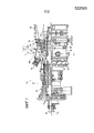
фиг. 1 - выполненный с частичным разрезом вид сбоку газотурбинного двигателя, включающего в себя систему рециркуляции воздуха оболочки камер сгорания в соответствии с одним вариантом осуществления изобретения;FIG. 1 is a partially cutaway side view of a gas turbine engine including an air recirculation system for a shell of a combustion chamber in accordance with one embodiment of the invention;
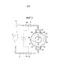
фиг. 2 - схематическая иллюстрация системы рециркуляции воздуха оболочки камер сгорания, показанной на фиг.1; иFIG. 2 is a schematic illustration of an air recirculation system of a shell of a combustion chamber shown in FIG. 1; and
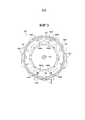
фиг. 3 - сечение части системы рециркуляции воздуха оболочки камер сгорания в соответствии с другим аспектом изобретения.FIG. 3 is a sectional view of a portion of an air recirculation system of a shell of combustion chambers in accordance with another aspect of the invention.
В нижеприведенном подробном описании предпочтительных вариантов осуществления сделана ссылка на сопровождающие чертежи, которые образуют часть описания и в которых в качестве иллюстрации, а не в качестве ограничения, показаны определенные предпочтительные варианты осуществления, в которых изобретение может быть реализовано на практике. Следует понимать, что могут быть использованы другие варианты осуществления и что могут быть выполнены изменения без отхода от сущности и объема настоящего изобретения.In the following detailed description of preferred embodiments, reference is made to the accompanying drawings, which form part of the description and in which, by way of illustration and not by way of limitation, certain preferred embodiments are shown in which the invention may be practiced. It should be understood that other embodiments may be used and that changes may be made without departing from the spirit and scope of the present invention.
На фиг. 1 показан газотурбинный двигатель 10, выполненный с конструкцией в соответствии с настоящим изобретением. Двигатель 10 включает в себя компрессорную секцию 12, секцию 14 сжигания, включающую в себя множество камер 16 сгорания, также называемых в документе «устройствами для сжигания», и турбинную секцию 18. Следует отметить, что на фиг. 1 для ясности проиллюстрирована только одна камера 16 сгорания, но двигатель 10 в соответствии с настоящим изобретением предпочтительно содержит упорядоченный ряд расположенных по кольцу камер 16 сгорания, которые расположены вокруг продольной оси LA двигателя 10, которая определяет аксиальное направление в двигателе 10. Подобную конфигурацию обычно называют «системой трубчатых, расположенных по кольцу камер сгорания».In FIG. 1 shows a
Компрессорная секция 12 обеспечивает всасывание и повышение давления входящего воздуха, по меньшей мере, часть которого направляется в оболочку 20 камер сгорания для подачи в камеры 16 сгорания. Воздух, находящийся в оболочке 20 камер сгорания, в дальнейшем назван «воздухом оболочки». Другие части воздуха по давлением могут быть отведены из секции 12 сжигания для охлаждения различных компонентов в двигателе 10.The
При входе в камеры 16 сгорания сжатый воздух из компрессорной секции 12 смешивается с топливом и воспламеняется для образования имеющих высокую температуру газообразных продуктов сгорания, проходящих турбулентно и с высокой скоростью внутри соответствующей камеры 16 сгорания. Газообразные продукты сгорания в каждой камере 16 сгорания затем проходят по соответствующему переходному каналу 22 к турбинной секции 18, в которой газообразные продукты сгорания расширяются для выделения энергии из них. Энергия, выделенная из газообразных продуктов сгорания, используется для обеспечения вращения ротора 24 турбины, который простирается параллельно вращающемуся валу 26, который проходит в аксиальном направлении через двигатель 10.Upon entering the
Как показано на фиг. 1, кожух 30 двигателя предусмотрен для ограждения соответствующих секций 12, 14, 18 двигателя. Часть 30А кожуха 30, расположенная вокруг секции 14 сжигания, содержит стенку 32 кожуха, которая определяет границы оболочки 20 камер сгорания, то есть оболочка 20 камер сгорания образует внутренний объем внутри части 30А кожуха. Как показано на фиг. 2, стенка 32 кожуха включает в себя верхнюю часть 32А стенки, левую и правую боковые части 32В, 32С стенки и нижнюю часть 32D стенки. Верхняя часть 32А стенки образует верхнюю мертвую точку 34 стенки 32 кожуха, которая представляет собой самую верхнюю зону части 30А кожуха, и нижняя часть 32D стенки образует нижнюю мертвую точку 36 стенки 32 кожуха, которая представляет собой самую нижнюю зону части 30А кожуха.As shown in FIG. 1, the
Далее будет описана система 40 рециркуляции воздуха оболочки в соответствии с одним аспектом настоящего изобретения. Как показано на фиг. 2, система 40 рециркуляции воздуха оболочки в показанном варианте осуществления содержит первый и второй выпускные элементы 42А, 42В, расположенные у нижней части 32D стенки, представляющей собой стенку 32 кожуха. Несмотря на то, что система 40 рециркуляции воздуха оболочки в соответствии с вариантом осуществления содержит первый и второй выпускные элементы 42А, 42В, может быть предусмотрено любое подходящее количество выпускных элементов, включая один выпускной элемент.Next, a shell
Как показано на фиг. 2, выпускные элементы 42А, 42В расположены на определенном расстоянии друг от друга по окружности и расположены по существу в одном и том же месте в аксиальном направлении, при этом нижняя мертвая точка 36 стенки 32 кожуха расположена между выпускными элементами 42А, 42В. В соответствии с одним аспектом изобретения, по меньшей мере, один из выпускных элементов 42А, 42В может также функционировать в качестве трубы для добавления пара, предназначенной для направления пара высокого давления в оболочку 20 камер сгорания для обеспечения увеличения выходной мощности двигателя 10, а именно посредством обеспечения более высоких скоростей прохода газообразных продуктов сгорания через турбинную секцию 18.As shown in FIG. 2, the
Система 40 рециркуляции воздуха оболочки дополнительно содержит систему 44 трубопроводов, которая предусмотрена для перемещения воздуха оболочки, который отводится из оболочки 20 камер сгорания через выпускные элементы 42А, 42В, к первому и второму впускным элементам 46А, 46В, которые расположены у верхней части 32А стенки, представляющей собой стенку 32 кожуха. Несмотря на то, что система 40 рециркуляции воздуха оболочки в соответствии с вариантом осуществления содержит первый и второй впускные элементы 46А, 46В, может быть предусмотрено любое подходящее количество впускных элементов, включая один впускной элемент.The shell
Как показано на фиг. 2, впускные элементы 46А, 46В расположены на определенном расстоянии друг от друга по окружности и расположены по существу в одном и том же месте в аксиальном направлении, при этом первый впускной элемент 46А расположен рядом с левой боковой частью 32В стенки, представляющей собой стенку 32 кожуха, и второй впускной элемент 46В расположен рядом с правой боковой частью 32С стенки, представляющей собой стенку 32 кожуха. В соответствии с одним аспектом изобретения, по меньшей мере, один из впускных элементов 46А, 46В может также функционировать в качестве трубы для добавления пара, предназначенной для направления пара высокого давления в оболочку 20 камер сгорания.As shown in FIG. 2, the
Система 40 рециркуляции воздуха оболочки дополнительно содержит еще клапанную систему 48, содержащую первый и второй клапаны 48А, 48В в показанном варианте осуществления, и воздуходувку 50. Управляющее устройство 52 осуществляет управление клапанной системой 48 и воздуходувкой 50 для избирательного обеспечения возможности или предотвращения прохода воздуха оболочки через систему 44 трубопроводов из выпускных элементов 42А, 42В к впускным элементам 46А, 46В, как будет подробно описано ниже. Воздуходувка 50 предусмотрена для отвода воздуха оболочки из оболочки 20 камер сгорания через выпускные элементы 42А, 42В и для перемещения отведенного воздуха оболочки к впускным элементам 46А, 46В, когда клапанная система 48 открыта.The sheath
Далее будет описан способ использования системы 40 рециркуляции воздуха оболочки. Во время нормальной работы двигателя 10, также известной как работа при полной нагрузке или базисный режим работы и также называемой в документе первым режимом работы двигателя, первый и второй клапаны 48А, 48В закрыты, и воздуходувка 50 выключена или не функционирует по другой причине. Следовательно, клапанная система 48 по существу предотвращает прохождение воздуха оболочки через систему 44 трубопроводов. По меньшей мере, часть воздуха оболочки подается в камеры 16 сгорания для сжигания части воздуха вместе с топливом, как рассмотрено выше. Дополнительные части воздуха оболочки могут быть использованы для охлаждения различных компонентов в двигателе 10, как будет очевидно для специалистов в области техники.Next, a method of using the shell
При инициировании операции перехода к работе при неполной нагрузке, которая выполняется для обеспечения перевода двигателя 10 в выключенное состояние или состояние проворачивания, постепенно прекращается подача топлива и воздуха оболочки в камеры 16 сгорания, так что образование имеющих высокую температуру газообразных продуктов сгорания в камерах 16 сгорания постепенно уменьшается до нуля при переводе двигателя 10 к выключенному состоянию или состоянию проворачивания. Когда газообразные продукты сгорания больше не образуются в камерах 16 сгорания, невозможно будет осуществить вращение ротора 24 турбины за счет газообразных продуктов сгорания. В такой ситуации медленное вращение ротора 24 турбины может быть осуществлено за счет подвода энергии от внешнего источника (не показано), например, за счет пускового двигателя, в рабочем состоянии, называемом в документе состоянием проворачивания. В альтернативном варианте вращение ротора 24 турбины может быть полностью остановлено в рабочем состоянии, называемом в документе выключенным состоянием. В типовом двигателе 10 подобная операция перехода к работе при неполной нагрузке может занимать, по меньшей мере, приблизительно 10-15 минут для полного перевода двигателя 10 в состояние проворачивания, при этом в течение времени сжигание при постепенно снижающемся уровне продолжается в камерах 16 сгорания для образования имеющих высокую температуру, газообразных продуктов сгорания, которые перемещаются в турбинную секцию 18 для обеспечения вращения ротора 24 турбины. Подразумевается, что второй режим работы двигателя в используемом в документе смысле охватывает операцию перехода к работе при неполной нагрузке, состояние проворачивания или выключенное состояние двигателя 10.When initiating the operation transition to a part-load operation, which is performed to ensure that the
В соответствии с одним аспектом настоящего изобретения при инициировании операции перехода к работе при неполной нагрузке для перевода двигателя 10 или в состояние проворачивания, или в выключенное состояние управляющее устройство 52 обеспечивает открытие первого и второго клапанов 48А, 48В так, что клапанная система 48 обеспечивает возможность прохода воздуха через систему 44 трубопроводов. Управляющее устройство 52 обеспечивает включение воздуходувки 50 во время второго режима работы для отвода воздуха оболочки от нижней части 32D стенки, представляющей собой стенку 32 кожуха, через выпускные элементы 42А, 42В. Воздуходувка 50 обеспечивает перемещение, то есть нагнетание отводимого воздуха оболочки через систему 44 трубопроводов так, что отведенный воздух оболочки вдувается к верхней части 32А стенки, представляющей собой стенку 32 кожуха, через впускные элементы 46А, 46В.In accordance with one aspect of the present invention, when initiating a transition to a partial load operation to put the
В соответствии с другим аспектом изобретения операция перехода к работе при неполной нагрузке может быть выполнена для обеспечения перехода двигателя 10 от работы при полной нагрузке в состояние проворачивания, которое может выполняться в течение заданного времени или до тех пор, пока один или несколько выбранных компонентов двигателя не достигнут заданной температуры, при этом в этот момент двигатель 10 может быть переведен в выключенное состояние. При конфигурации при состоянии проворачивания клапаны 48А, 48В удерживаются в открытых положениях, и работа воздуходувки 50 продолжается для отвода воздуха оболочки от нижней части 32D стенки, представляющей собой стенку 32 кожуха, через выпускные элементы 42А, 42В, для перемещения отведенного воздуха оболочки через систему 44 трубопроводов и для вдувания отведенного воздуха оболочки к верхней части 32А стенки, представляющей собой стенку 32 кожуха, через впускные элементы 46А, 46В. Однако при переходе двигателя 10 в выключенное состояние, то есть после завершения выполнения проворачивания, воздуходувка 50 может быть выключена или заблокирована иным образом для прекращения нагнетания воздуха оболочки через систему 44 трубопроводов. При выключенном состоянии клапаны 48А, 48В могут оставаться открытыми, или управляющее устройство 52 может обеспечить их закрытие, но они будут закрыты управляющим устройством 52 при инициировании процедуры запуска двигателя.In accordance with another aspect of the invention, a partial-load operation operation can be performed to enable the
Как показано на фиг. 2, воздух, вдуваемый посредством впускных элементов 46А, 46В в оболочку 20 камер сгорания, проходит от верхней части 32А стенки, представляющей собой стенку 32 кожуха, вниз вдоль соответствующих левой и правой боковых частей 32В, 32С стенки к нижней части 32D стенки. Таким образом, система 40 рециркуляции воздуха оболочки функционирует для обеспечения циркуляции воздуха оболочки в оболочке 20 камер сгорания во время работы при нагрузке меньшей, чем полная нагрузка, для создания более равномерного распределения температур воздуха оболочки в оболочке 20 камер сгорания. В противном случае более горячий воздух оболочки будет стремиться к перемещению к верхней части 32А стенки, что приводит к более высоким температурам у верхней части 32А стенки, чем у нижней части 32D стенки. Кроме того, воздух оболочки у нижней части 32D стенки, который отводится через выпускные элементы 42А, 42В посредством воздуходувки 50 и вдувается через впускные элементы 46А, 46В, как правило, является более холодным, чем воздух оболочки у верхней части 32А стенки, что приводит к еще более равномерному распределению температур воздуха оболочки в пределах оболочки 20 камер сгорания.As shown in FIG. 2, air blown through the
Полагают, что более равномерное распределение температур воздуха оболочки в пределах оболочки 20 камер сгорания, обеспечиваемое посредством системы 40 рециркуляции воздуха оболочки, уменьшает остроту проблем или предотвращает проблемы, которые могли бы возникнуть в результате того, что компоненты, находящиеся в пределах и вокруг оболочки 20 камер сгорания, подвергаются тепловому расширению с разными скоростями, такие как деформация кожуха 30 двигателя и/или трение вершин TT турбинных лопаток в турбинной секции 18 о кожух 30, в результате чего увеличивается продолжительность эксплуатации компонентов и сохраняется жестко ограниченный радиальный зазор между вершинами турбинных лопаток и стенкой кожуха во время работы при полной нагрузке для повышения КПД турбины. Следует отметить, что, поскольку система 40 рециркуляции воздуха оболочки в соответствии с настоящим изобретением обеспечивает вдувание только воздуха оболочки в оболочку 20 камер сгорания и при этом воздух оболочки отводится от нижней части 32D стенки через выпускные элементы 42А, 42В посредством воздуходувки 50, уменьшаются стоимость и сложность системы 40 рециркуляции воздуха оболочки, например, по сравнению с системой, в которой используется такой конструктивный элемент, как эжектор, для вдувания воздуха высокого давления в оболочку 20 камер сгорания.It is believed that a more uniform distribution of shell air temperatures within the
Как отмечено выше, один или несколько из выпускных и впускных элементов 42А, 42В, 46А, 46В могут также функционировать в качестве труб для добавления пара для направления пара высокого давления в оболочку 20 камер сгорания для обеспечения повышения выходной мощности двигателя 10. Подобный ввод пара, как правило, выполняется только во время работы при полной нагрузке. Если какие-либо из выпускных и впускных элементов 42А, 42В, 46А, 46В также функционируют в качестве труб для добавления пара, элементы 42А, 42В, 46А, 46В предпочтительно проходят прямолинейно в стенку 32 кожуха и заканчиваются на коротком расстоянии от нее в оболочке 20 камер сгорания, как показано на фиг. 1 и 2. Использование выпускных и впускных элементов 42А, 42В, 46А, 46В в качестве труб для добавления пара может быть особенно предпочтительным, если система 40 рециркуляции воздуха оболочки реализуется в существующем двигателе 10, то есть в модифицированной конструкции, поскольку не потребуются дополнительные трубы, которые проходят через стенку 32 кожуха, в результате чего уменьшается сложность монтажа системы 40 рециркуляции воздуха оболочки в существующем двигателе 10.As noted above, one or more of the exhaust and
Если выпускные и впускные элементы 42А, 42В, 46А, 46В не должны функционировать в качестве труб для добавления пара, один или несколько из элементов 42А, 42В, 46А, 46В могут иметь концы с особой конфигурацией для изменения отвода воздуха оболочки из оболочки 20 камер сгорания и/или вдувания воздуха оболочки в оболочку 20 камер сгорания. Например, на фиг. 3 показана система 140 рециркуляции воздуха оболочки, выполненная с конструкцией в соответствии с другим вариантом осуществления изобретения, в которой конструктивные элементы, аналогичные конструктивным элементам, описанным выше со ссылкой на фиг. 1 и 2, имеют те же самые ссылочные номера, увеличенные на 100. Кроме того, только конструктивные элементы, которые отличаются от варианта осуществления, рассмотренного выше со ссылкой на фиг. 1 и 2, будут рассмотрены в документе для фиг. 3. В качестве исходного пункта вид системы 140 рециркуляции воздуха оболочки, показанной на фиг. 3, выполнен вдоль линии 3-3, проиллюстрированной на фиг. 1, и выбранные компоненты двигателя 110 и системы 140 рециркуляции воздуха оболочки были удалены из фиг. 3 для ясности.If the exhaust and
В варианте осуществления выпускные элементы 142А, 142В имеют концы 142A1, 142B1 конической формы для увеличения количества воздуха оболочки, который может быть отведен посредством них.In an embodiment, the
Кроме того, впускные элементы 146А, 146В в соответствии с вариантом осуществления имеют концы 146A1, 146B1, которые имеют наклон в направлении вдоль окружности по направлению друг к другу и также имеют наклон в аксиальном направлении по направлению к компрессорной секции (не показано в варианте осуществления) и от турбинной секции (не показано в варианте осуществления). Таким образом, впускные элементы 146А, 146В в соответствии с вариантом осуществления выполнены с такой конфигурацией, что они обеспечивают вдувание воздуха оболочки, по меньшей мере, частично в направлении вдоль окружности по направлению друг к другу и к верхней мертвой точке 134 стенки 132 кожуха, которая расположена в направлении вдоль окружности между первым и вторым впускными элементами 146А, 146В, как показано на фиг. 3, то есть воздух оболочки, вдуваемый посредством впускных элементов 146А, 146В, имеет окружную составляющую вектора скорости.In addition, the
После прохода к верхней мертвой точке 134 стенки 132 кожуха воздух, вдуваемый посредством впускных элементов 146А, 146В, проходит от верхней части 132А стенки, представляющей собой стенку 132 кожуха, вниз вдоль соответствующих левой и правой боковых частей 132В, 132С стенки к нижней части 132D стенки. Поскольку воздух, вдуваемый посредством впускных элементов 146А, 146В, в соответствии с вариантом осуществления проходит к верхней мертвой точке 134 стенки 132 кожуха, полагают, что гарантируется то, что воздух оболочки, находящийся у верхней мертвой точки 134 стенки 132 кожуха, который может представлять собой самый горячий воздух оболочки в пределах оболочки 120 камер сгорания, будет подвергаться циркуляции вместе с остальным воздухом оболочки. Кроме того, поскольку воздух оболочки, вдуваемый посредством впускных элементов 146А, 146В, в соответствии с вариантом осуществления также проходит в аксиальном направлении к компрессорной секции двигателя 110, то есть воздух оболочки, вдуваемый посредством впускных элементов 146А, 146В, имеет аксиальную составляющую вектора скорости, полагают, что гарантируется то, что большее количество воздуха оболочки в оболочке 120 камер сгорания будет подвергаться циркуляции.After passing to the top
Следует отметить, что выпускные и впускные элементы, описанные в документе, могут быть расположены в других местах в аксиальном направлении в части кожуха, отличающихся от мест, показанных на фиг. 1-3. Кроме того, несколько рядов выпускных и впускных элементов могут быть использованы для дополнительного улучшения циркуляции воздуха оболочки в оболочке камер сгорания.It should be noted that the outlet and inlet elements described in the document may be located in other places in the axial direction in the part of the casing, different from the places shown in FIG. 1-3. In addition, several rows of exhaust and intake elements can be used to further improve the air circulation of the shell in the shell of the combustion chambers.
Также следует отметить, что в случае использования только одного впускного элемента, то есть в отличие от использования первого и второго впускных элементов в вариантах осуществления, рассмотренных выше, единственный впускной элемент может быть выполнен с конфигурацией, обеспечивающей возможность вдувания воздуха вниз вдоль обеих, то есть левой и правой, боковых частей стенки, представляющей собой стенку кожуха. К примерам подобного впускного элемента относится впускной элемент с двумя концами, в котором первый конец направлен к левой боковой части стенки и правый конец направлен к правой боковой части стенки, или впускной элемент может иметь створки или ребра, которые предусмотрены для вдувания воздуха в заданных направлениях. Кроме того, подобный единственный впускной элемент может быть расположен у верхней мертвой точки стенки кожуха для обеспечения более эффективной циркуляции воздуха в оболочке камер сгорания. Кроме того, подобный единственный впускной элемент также может быть выполнен с такой конфигурацией, что воздух оболочки, вдуваемый посредством него, будет иметь аксиальную составляющую вектора скорости.It should also be noted that in the case of using only one inlet element, that is, in contrast to the use of the first and second inlet elements in the embodiments discussed above, the only inlet element can be configured to allow air to be blown down along both, i.e. left and right side parts of the wall, which is the wall of the casing. Examples of such an inlet element include a two-end inlet element in which the first end is directed to the left side of the wall and the right end is directed to the right side of the wall, or the inlet element may have flaps or ribs that are provided for blowing air in predetermined directions. In addition, such a single inlet element can be located at the top dead center of the casing wall to provide more efficient air circulation in the shell of the combustion chambers. In addition, such a single inlet element can also be configured so that the air of the shell, blown through it, will have an axial component of the velocity vector.
Несмотря на то, что определенные варианты осуществления настоящего изобретения были проиллюстрированы и описаны, специалистам в области техники будет очевидно, что различные другие изменения и модификации могут быть выполнены без отхода от сущности и объема изобретения. Следовательно, предусмотрено, что приложенная формула изобретения охватывает все подобные изменения и модификации, которые находятся в пределах объема изобретения.Although certain embodiments of the present invention have been illustrated and described, it will be apparent to those skilled in the art that various other changes and modifications can be made without departing from the spirit and scope of the invention. Therefore, it is contemplated that the appended claims cover all such alterations and modifications that are within the scope of the invention.
Claims (34)
Applications Claiming Priority (3)
| Application Number | Priority Date | Filing Date | Title |
|---|---|---|---|
| US13/603,804 US8820090B2 (en) | 2012-09-05 | 2012-09-05 | Method for operating a gas turbine engine including a combustor shell air recirculation system |
| US13/603,804 | 2012-09-05 | ||
| PCT/US2013/056720 WO2014039315A1 (en) | 2012-09-05 | 2013-08-27 | Method for operating a gas turbine engine including a combustor shell air recirculation system |
Publications (2)
| Publication Number | Publication Date |
|---|---|
| RU2015107576A RU2015107576A (en) | 2016-10-27 |
| RU2626047C2 true RU2626047C2 (en) | 2017-07-21 |
Family
ID=49151327
Family Applications (1)
| Application Number | Title | Priority Date | Filing Date |
|---|---|---|---|
| RU2015107576A RU2626047C2 (en) | 2012-09-05 | 2013-08-27 | Method of operation a gas turbine engine including the system of air recirculation in the combustion chamber shell |
Country Status (8)
| Country | Link |
|---|---|
| US (1) | US8820090B2 (en) |
| EP (1) | EP2893157A1 (en) |
| JP (1) | JP6211616B2 (en) |
| CN (1) | CN104619958B (en) |
| IN (1) | IN2015DN00894A (en) |
| RU (1) | RU2626047C2 (en) |
| SA (1) | SA515360105B1 (en) |
| WO (1) | WO2014039315A1 (en) |
Families Citing this family (14)
| Publication number | Priority date | Publication date | Assignee | Title |
|---|---|---|---|---|
| US8973372B2 (en) * | 2012-09-05 | 2015-03-10 | Siemens Aktiengesellschaft | Combustor shell air recirculation system in a gas turbine engine |
| US20140301820A1 (en) * | 2013-04-03 | 2014-10-09 | Uwe Lohse | Turbine engine shutdown temperature control system with nozzle injection for a gas turbine engine |
| US20150107255A1 (en) * | 2013-10-18 | 2015-04-23 | General Electric Company | Turbomachine combustor having an externally fueled late lean injection (lli) system |
| GB2526784A (en) | 2014-05-26 | 2015-12-09 | Skf Ab | Micro electro optical mechanical system |
| US9869190B2 (en) | 2014-05-30 | 2018-01-16 | General Electric Company | Variable-pitch rotor with remote counterweights |
| US20160061060A1 (en) * | 2014-08-28 | 2016-03-03 | General Electric Company | Combined cycle power plant thermal energy conservation |
| US10072510B2 (en) | 2014-11-21 | 2018-09-11 | General Electric Company | Variable pitch fan for gas turbine engine and method of assembling the same |
| US10100653B2 (en) | 2015-10-08 | 2018-10-16 | General Electric Company | Variable pitch fan blade retention system |
| US10794281B2 (en) | 2016-02-02 | 2020-10-06 | General Electric Company | Gas turbine engine having instrumented airflow path components |
| US11073090B2 (en) * | 2016-03-30 | 2021-07-27 | General Electric Company | Valved airflow passage assembly for adjusting airflow distortion in gas turbine engine |
| US10753278B2 (en) | 2016-03-30 | 2020-08-25 | General Electric Company | Translating inlet for adjusting airflow distortion in gas turbine engine |
| US11674435B2 (en) | 2021-06-29 | 2023-06-13 | General Electric Company | Levered counterweight feathering system |
| US11795964B2 (en) | 2021-07-16 | 2023-10-24 | General Electric Company | Levered counterweight feathering system |
| US11668206B1 (en) * | 2022-03-09 | 2023-06-06 | General Electric Company | Temperature gradient control system for a compressor casing |
Citations (5)
| Publication number | Priority date | Publication date | Assignee | Title |
|---|---|---|---|---|
| RU2161715C2 (en) * | 1999-02-08 | 2001-01-10 | Открытое акционерное общество Научно-производственное объединение "Искра" | Gas-turbine unit cooling device |
| US7329084B2 (en) * | 2001-10-30 | 2008-02-12 | Alstom Technology Ltd | Turbomachine |
| US7682130B2 (en) * | 2004-08-23 | 2010-03-23 | Alstom Technology Ltd | Device and method for cooling a housing of a gas turbine or a combustion chamber |
| US20100280733A1 (en) * | 2009-05-04 | 2010-11-04 | General Electric Company | Gas turbine shutdown |
| RU2414649C2 (en) * | 2009-04-30 | 2011-03-20 | Российская Федерация, От Имени Которой Выступает Министерство Промышленности И Торговли Российской Федерации | Gas turbine engine combustion chamber |
Family Cites Families (16)
| Publication number | Priority date | Publication date | Assignee | Title |
|---|---|---|---|---|
| JPS5761123B2 (en) * | 1974-04-26 | 1982-12-23 | Hitachi Ltd | |
| JPH06193407A (en) * | 1992-12-24 | 1994-07-12 | Toshiba Corp | Turbine casing forced cooling device |
| JP3234679B2 (en) * | 1993-06-25 | 2001-12-04 | 株式会社東芝 | Steam turbine cooling method |
| JP3233824B2 (en) * | 1995-08-07 | 2001-12-04 | 三菱重工業株式会社 | Steam cooled combustor |
| JP2002523661A (en) * | 1998-08-18 | 2002-07-30 | シーメンス アクチエンゲゼルシヤフト | Turbine casing |
| WO2004090291A1 (en) | 2003-04-07 | 2004-10-21 | Alstom Technology Ltd | Turbomachine |
| DE10352089A1 (en) | 2003-11-07 | 2005-06-09 | Alstom Technology Ltd | Method for operating a turbomachine, and turbomachinery |
| JP2006037855A (en) * | 2004-07-28 | 2006-02-09 | Mitsubishi Heavy Ind Ltd | Cylinder casing and gas turbine |
| US7987660B2 (en) | 2005-06-10 | 2011-08-02 | Mitsubishi Heavy Industries, Ltd. | Gas turbine, method of controlling air supply and computer program product for controlling air supply |
| US7841186B2 (en) * | 2007-01-31 | 2010-11-30 | Power Systems Mfg., Llc | Inlet bleed heat and power augmentation for a gas turbine engine |
| US8495883B2 (en) | 2007-04-05 | 2013-07-30 | Siemens Energy, Inc. | Cooling of turbine components using combustor shell air |
| US20090056342A1 (en) | 2007-09-04 | 2009-03-05 | General Electric Company | Methods and Systems for Gas Turbine Part-Load Operating Conditions |
| US8061971B2 (en) | 2008-09-12 | 2011-11-22 | General Electric Company | Apparatus and method for cooling a turbine |
| US8210801B2 (en) * | 2009-01-29 | 2012-07-03 | General Electric Company | Systems and methods of reducing heat loss from a gas turbine during shutdown |
| US20110271689A1 (en) * | 2010-05-06 | 2011-11-10 | General Electric Company | Gas turbine cooling |
| US8973372B2 (en) * | 2012-09-05 | 2015-03-10 | Siemens Aktiengesellschaft | Combustor shell air recirculation system in a gas turbine engine |
-
2012
- 2012-09-05 US US13/603,804 patent/US8820090B2/en not_active Expired - Fee Related
-
2013
- 2013-08-27 RU RU2015107576A patent/RU2626047C2/en not_active IP Right Cessation
- 2013-08-27 IN IN894DEN2015 patent/IN2015DN00894A/en unknown
- 2013-08-27 WO PCT/US2013/056720 patent/WO2014039315A1/en active Application Filing
- 2013-08-27 JP JP2015531122A patent/JP6211616B2/en not_active Expired - Fee Related
- 2013-08-27 EP EP13759929.6A patent/EP2893157A1/en not_active Withdrawn
- 2013-08-27 CN CN201380046318.7A patent/CN104619958B/en not_active Expired - Fee Related
-
2015
- 2015-03-03 SA SA515360105A patent/SA515360105B1/en unknown
Patent Citations (5)
| Publication number | Priority date | Publication date | Assignee | Title |
|---|---|---|---|---|
| RU2161715C2 (en) * | 1999-02-08 | 2001-01-10 | Открытое акционерное общество Научно-производственное объединение "Искра" | Gas-turbine unit cooling device |
| US7329084B2 (en) * | 2001-10-30 | 2008-02-12 | Alstom Technology Ltd | Turbomachine |
| US7682130B2 (en) * | 2004-08-23 | 2010-03-23 | Alstom Technology Ltd | Device and method for cooling a housing of a gas turbine or a combustion chamber |
| RU2414649C2 (en) * | 2009-04-30 | 2011-03-20 | Российская Федерация, От Имени Которой Выступает Министерство Промышленности И Торговли Российской Федерации | Gas turbine engine combustion chamber |
| US20100280733A1 (en) * | 2009-05-04 | 2010-11-04 | General Electric Company | Gas turbine shutdown |
Also Published As
| Publication number | Publication date |
|---|---|
| JP2015529301A (en) | 2015-10-05 |
| CN104619958B (en) | 2016-08-31 |
| EP2893157A1 (en) | 2015-07-15 |
| IN2015DN00894A (en) | 2015-06-12 |
| US20140060068A1 (en) | 2014-03-06 |
| JP6211616B2 (en) | 2017-10-11 |
| WO2014039315A1 (en) | 2014-03-13 |
| US8820090B2 (en) | 2014-09-02 |
| CN104619958A (en) | 2015-05-13 |
| SA515360105B1 (en) | 2015-11-25 |
| RU2015107576A (en) | 2016-10-27 |
Similar Documents
| Publication | Publication Date | Title |
|---|---|---|
| RU2626047C2 (en) | Method of operation a gas turbine engine including the system of air recirculation in the combustion chamber shell | |
| RU2595465C1 (en) | Air circulation system shell of combustion chambers in gas turbine engine | |
| CN106460550B (en) | There is the gas-turbine unit of cooling system in rotor pair in exhaust diffuser | |
| US8820091B2 (en) | External cooling fluid injection system in a gas turbine engine | |
| US8893510B2 (en) | Air injection system in a gas turbine engine | |
| JPH02218821A (en) | Turbine engine and cooling method | |
| GB2117842A (en) | Means for equalising the temperatures within a gas turbine engine | |
| JP2007182785A (en) | Gas turbine, method for starting gas turbine and combined-cycle power generation system | |
| US10590944B2 (en) | Cooling system for compressor and method for operation thereof | |
| TW201623779A (en) | Gas turbine clearance control including radiant heater | |
| US11371378B2 (en) | Apparatus for controlling turbine blade tip clearance and gas turbine including the same | |
| EP3456922B1 (en) | Turbine blade with cooling structure, turbine including same turbine blade, and gas turbine including same turbine | |
| US10669860B2 (en) | Gas turbine blade | |
| KR101984402B1 (en) | Compressor and gas turbine comprising the same | |
| KR101967062B1 (en) | Apparatus for preheating compressor and gas turbine comprising the same | |
| KR102212880B1 (en) | Gas turbine | |
| US20180266320A1 (en) | Extraction cooling system using evaporative media for turbine cooling | |
| JP2003328771A (en) | Cooling fluid circulating system recombustion combined cycle combination gas turbine | |
| RU2000133208A (en) | GAS TURBINE ENGINE |
Legal Events
| Date | Code | Title | Description |
|---|---|---|---|
| MM4A | The patent is invalid due to non-payment of fees |
Effective date: 20190828 |