RU2623503C2 - Unit for overvoltage protection device and relevant overvoltage protection device - Google Patents
Unit for overvoltage protection device and relevant overvoltage protection device Download PDFInfo
- Publication number
- RU2623503C2 RU2623503C2 RU2012152603A RU2012152603A RU2623503C2 RU 2623503 C2 RU2623503 C2 RU 2623503C2 RU 2012152603 A RU2012152603 A RU 2012152603A RU 2012152603 A RU2012152603 A RU 2012152603A RU 2623503 C2 RU2623503 C2 RU 2623503C2
- Authority
- RU
- Russia
- Prior art keywords
- surge protection
- block
- overvoltage protection
- protection component
- temperature
- Prior art date
Links
Images

Classifications
-
- H—ELECTRICITY
- H01—ELECTRIC ELEMENTS
- H01H—ELECTRIC SWITCHES; RELAYS; SELECTORS; EMERGENCY PROTECTIVE DEVICES
- H01H9/00—Details of switching devices, not covered by groups H01H1/00 - H01H7/00
- H01H9/20—Interlocking, locking, or latching mechanisms
- H01H9/22—Interlocking, locking, or latching mechanisms for interlocking between casing, cover, or protective shutter and mechanism for operating contacts
-
- H—ELECTRICITY
- H01—ELECTRIC ELEMENTS
- H01C—RESISTORS
- H01C7/00—Non-adjustable resistors formed as one or more layers or coatings; Non-adjustable resistors made from powdered conducting material or powdered semi-conducting material with or without insulating material
- H01C7/10—Non-adjustable resistors formed as one or more layers or coatings; Non-adjustable resistors made from powdered conducting material or powdered semi-conducting material with or without insulating material voltage responsive, i.e. varistors
- H01C7/12—Overvoltage protection resistors; Arresters
- H01C7/126—Means for protecting against excessive pressure or for disconnecting in case of failure
-
- H—ELECTRICITY
- H01—ELECTRIC ELEMENTS
- H01H—ELECTRIC SWITCHES; RELAYS; SELECTORS; EMERGENCY PROTECTIVE DEVICES
- H01H37/00—Thermally-actuated switches
- H01H37/74—Switches in which only the opening movement or only the closing movement of a contact is effected by heating or cooling
- H01H37/76—Contact member actuated by melting of fusible material, actuated due to burning of combustible material or due to explosion of explosive material
-
- H—ELECTRICITY
- H01—ELECTRIC ELEMENTS
- H01T—SPARK GAPS; OVERVOLTAGE ARRESTERS USING SPARK GAPS; SPARKING PLUGS; CORONA DEVICES; GENERATING IONS TO BE INTRODUCED INTO NON-ENCLOSED GASES
- H01T1/00—Details of spark gaps
- H01T1/14—Means structurally associated with spark gap for protecting it against overload or for disconnecting it in case of failure
-
- H—ELECTRICITY
- H01—ELECTRIC ELEMENTS
- H01H—ELECTRIC SWITCHES; RELAYS; SELECTORS; EMERGENCY PROTECTIVE DEVICES
- H01H83/00—Protective switches, e.g. circuit-breaking switches, or protective relays operated by abnormal electrical conditions otherwise than solely by excess current
- H01H83/10—Protective switches, e.g. circuit-breaking switches, or protective relays operated by abnormal electrical conditions otherwise than solely by excess current operated by excess voltage, e.g. for lightning protection
Landscapes
- Engineering & Computer Science (AREA)
- Microelectronics & Electronic Packaging (AREA)
- Physics & Mathematics (AREA)
- Electromagnetism (AREA)
- Chemical & Material Sciences (AREA)
- Combustion & Propulsion (AREA)
- Fuses (AREA)
- Emergency Protection Circuit Devices (AREA)
- Thermally Actuated Switches (AREA)
Abstract
Description
ОБЛАСТЬ ТЕХНИКИFIELD OF TECHNOLOGY
Настоящее изобретение относится к общей технической области устройств защиты электрических приборов или оборудования от электрических возмущений, в частности, от переходных перенапряжений.The present invention relates to the general technical field of devices for protecting electrical appliances or equipment against electrical disturbances, in particular against transient overvoltages.
ПРЕДШЕСТВУЮЩИЙ УРОВЕНЬ ТЕХНИКИ BACKGROUND OF THE INVENTION
Использование устройств защиты от перенапряжений хорошо известно. Как правило, в таких устройствах в качестве компонента защиты от перенапряжений применяют варистор. Действительно, варистор ограничивает сверху перенапряжение, начиная от заранее определенного значения, и позволяет ограничить распространение перенапряжения в электрической сети.The use of surge protection devices is well known. Typically, in such devices, a varistor is used as a component of surge protection. Indeed, the varistor limits the overvoltage from above, starting from a predetermined value, and allows you to limit the propagation of overvoltage in the electrical network.
По мере эксплуатации такие компоненты подвергаются износу, их полное сопротивление постепенно понижается, что приводит к увеличению их силы тока утечки и, следовательно, способствует значительному нагреву варистора за счет эффекта Джоуля. Этот нагрев переходит на соседние приборы, что может привести к пожару или к короткому замыканию.During operation, such components undergo wear and tear, their impedance gradually decreases, which leads to an increase in their leakage current and, therefore, contributes to a significant heating of the varistor due to the Joule effect. This heating transfers to neighboring appliances, which can lead to fire or short circuit.
Чтобы избежать возможного повреждения электрического прибора или оборудования, соединенного с устройством, необходимо обеспечить возможность отключения этого устройства при окончательном выходе из строя варистора.In order to avoid possible damage to the electrical appliance or equipment connected to the device, it is necessary to ensure that this device can be turned off when the varistor fails.
Такое устройство разъединения, называемое устройством теплового разъединения, предназначено для отключения устройства защиты от перенапряжений, содержащего неисправный варистор, при повышении температуры сверх определенного критического предела.Such a disconnect device, called a thermal disconnect device, is designed to disable the surge protection device containing the faulty varistor when the temperature rises above a certain critical limit.
Так, в документе FR2848353 описано устройство защиты электрического прибора от перенапряжений, которое содержит:So, in the document FR2848353 describes a device for protecting an electrical device from overvoltage, which contains:
- защитный блок, соединенный с электрическим прибором через соединительную цепь, содержащую средство прерывания электрического тока, выполненное с возможностью перемещения между возвратным положением, соответствующим размыканию цепи, и положением замыкания цепи, при этом упомянутое средство прерывания удерживают в положении замыкания при помощи блокировочного средства;- a protective unit connected to the electrical device through a connecting circuit containing means for interrupting the electric current, configured to move between the return position corresponding to the opening of the circuit and the position of the circuit, while said interrupt means is held in the locked position by means of a locking means;
- средство размыкания соединительной цепи, когда температура защитного блока достигает заранее определенного значения, содержащее термочувствительное средство. Это термочувствительное средство соединено с приводным средством таким образом, чтобы при достижении заранее определенной температуры приводное средство создало усилие деактивации блокировочного средства. Термочувствительное и приводное средства совпадают и выполнены в виде биметаллической пластинки.- means for opening the connecting circuit when the temperature of the protective unit reaches a predetermined value, containing heat-sensitive means. This heat-sensitive means is connected to the drive means so that when a predetermined temperature is reached, the drive means creates a deactivation force of the locking means. The heat-sensitive and driving means are the same and are made in the form of a bimetallic plate.
Такое устройство имеет недостатки. Действительно, биметаллическая пластинка, свойства которой меняются при повышении температуры, подвергается сильным механическим напряжениям, учитывая, что речь идет также о приводном элементе, который обеспечивает размыкание цепи. Следовательно, надежность такого устройства снижается в результате вибраций или толчков, действующих на устройство. Кроме того, на детектирование температуры биметаллической пластинки влияет ток, проходящий через средство теплового разъединения. Следовательно, размеры средства детектирования следует рассчитать таким образом, чтобы прохождение тока не влияло на средство разъединения.Such a device has disadvantages. Indeed, a bimetallic plate, the properties of which change with increasing temperature, is subjected to strong mechanical stresses, given that we are also talking about a drive element that provides circuit breaking. Therefore, the reliability of such a device is reduced as a result of vibrations or shocks acting on the device. In addition, the current passing through the thermal disconnect means affects the temperature detection of the bimetallic plate. Therefore, the dimensions of the detection means should be calculated so that the passage of current does not affect the disconnecting means.
В документе FR2925216 описано устройство защиты от перенапряжений, содержащее компонент защиты от перенапряжений, термически связанный с термочувствительным элементом, выполненным с возможностью деформирования в зависимости от своей температуры, и механический элемент, предназначенный для взаимодействия с термочувствительным элементами выполненный с возможностью взаимодействия с устройством срабатывания прибора отключения тока. Когда температура компонента защиты от перенапряжений превышает заранее определенный порог, деформация термочувствительного элемента приводит к перемещению механического элемента, который выходит за пределы блока, содержащего термочувствительный элемент и компонент защиты от перенапряжений, и приводит в действие устройство срабатывания прибора отключения тока.Document FR2925216 describes an overvoltage protection device comprising an overvoltage protection component thermally coupled to a thermosensitive element configured to deform depending on its temperature, and a mechanical element designed to interact with thermosensitive elements configured to interact with a trip device current. When the temperature of the overvoltage protection component exceeds a predetermined threshold, deformation of the heat-sensitive element leads to a movement of the mechanical element, which goes beyond the block containing the heat-sensitive element and the overvoltage protection component, and drives the device for tripping the current disconnecting device.
Это устройство защиты от перенапряжений механически связано с прибором отключения тока, таким образом, существует два блока, каждый из которых выполняет конкретные функции: с одной стороны, детектирование критической температуры нарушения в работе компонента защиты от перенапряжений и, с другой стороны, отключение неисправного защитного устройства от остальной части электрического оборудования.This surge protection device is mechanically connected to a current cutoff device, so there are two units, each of which performs specific functions: on the one hand, the detection of the critical temperature of the violation of the surge protection component and, on the other hand, the disconnection of a faulty protective device from the rest of the electrical equipment.
Недостатком такого устройства является необходимость использования двух блоков, что приводит к повышению стоимости изготовления и к потере места в электрической системе. Кроме того, защитное устройство и устройство прерывания расположены последовательно в контуре тока.The disadvantage of this device is the need to use two blocks, which leads to an increase in manufacturing costs and to a loss of space in the electrical system. In addition, the protective device and the interrupt device are arranged in series in the current loop.
Таким образом, согласно этим двум патентам, решения требуют, чтобы блокировочный элемент был электрическим проводником, например, из металла, с известными свойствами механической деформации и чтобы он мог преобразовать тепловое действие в механическое усилие.Thus, according to these two patents, the solutions require that the blocking element be an electrical conductor, for example of metal, with known mechanical deformation properties and that it can convert the thermal effect into mechanical force.
Кроме того, известны устройства защиты от перенапряжений, в которых время теплового разъединения является слишком большим, поскольку функциональное средство детектирования нагрева варистора слишком удалено от варистора, поэтому время реакции элемента детектирования не является достаточно коротким для обеспечения быстрого разъединения.In addition, surge protection devices are known in which the thermal disconnection time is too long, since the varistor heating detection means are too far from the varistor, therefore, the response time of the detection element is not short enough to allow quick disconnection.
КРАТКОЕ ИЗЛОЖЕНИЕ СУЩЕСТВА ИЗОБРЕТЕНИЯSUMMARY OF THE INVENTION
Таким образом, существует потребность в устройстве защиты от перенапряжений, характеризующемся быстрым тепловым разъединением и повышенной надежностью при уменьшении механических напряжений, действующих на элементы устройства, и позволяющем получить выигрыш по занимаемому месту в защищаемом электрическом приборе или оборудовании.Thus, there is a need for an overvoltage protection device, characterized by rapid thermal disconnection and increased reliability while reducing mechanical stresses acting on the elements of the device, and allowing gaining the occupied space in the protected electrical appliance or equipment.
Для устранения одного или нескольких вышеуказанных недостатков блок для устройства защиты от перенапряжений содержит:To eliminate one or more of the above disadvantages, the unit for the surge protection device contains:
- два элемента электрического соединения;- two elements of electrical connection;
- компонент защиты от перенапряжений, электрически связанный с двумя элементами электрического соединения, температура которого повышается при наличии перенапряжения;- component of surge protection, electrically connected to two elements of the electrical connection, the temperature of which increases in the presence of overvoltage;
- блокировочный элемент, находящийся в контакте с компонентом защиты от перенапряжений;- a blocking element in contact with the surge protection component;
- механический прерыватель, связанный с блокировочным элементом, установленный последовательно между одним из двух элементов электрического соединения и компонентом защиты от перенапряжений, при этом блокировочный элемент удерживает прерыватель в замкнутом положении, при этом, когда температура компонента защиты от перенапряжений превышает критический порог, блокировочный элемент освобождает прерыватель, который переходит в разомкнутое положение. Кроме того, блокировочный элемент является электрически независимым от механического прерывателя.- a mechanical breaker associated with the blocking element, mounted in series between one of the two electrical connection elements and the surge protection component, while the blocking element holds the breaker in the closed position, while when the temperature of the surge protection component exceeds a critical threshold, the blocking element releases breaker that goes into open position. In addition, the interlocking element is electrically independent of the mechanical chopper.
Таким образом, предпочтительно, поскольку блокировочный элемент не является частью контура тока, в котором участвует прерыватель, можно расположить блокировочный элемент таким образом, чтобы он быстро реагировал на выделение тепла, использовать материал, специально адаптированный для этой функции блокировки и не обязательно являющийся проводником.Thus, it is preferable since the blocking element is not part of the current circuit in which the interrupter is involved, it is possible to arrange the blocking element so that it reacts quickly to heat generation, use material specially adapted for this blocking function and not necessarily being a conductor.
Кроме того, когда температура компонента защиты от перенапряжений превышает критический порог, блокировочный элемент освобождает прерыватель, который переходит в разомкнутое положение.In addition, when the temperature of the surge protection component exceeds a critical threshold, the interlock releases the breaker, which switches to the open position.
Преимуществом такого блока для устройства защиты от перенапряжений является то, что он позволяет реализовать устройство с быстрым тепловым разъединением. Действительно, блокировочный элемент входит в контакт с компонентом защиты от перенапряжений и, следовательно, находится максимально близко к месту нагрева.An advantage of such a unit for an overvoltage protection device is that it makes it possible to realize a device with fast thermal disconnection. Indeed, the blocking element comes into contact with the surge protection component and, therefore, is located as close to the heating site as possible.
Кроме того, предпочтительно в этом блоке механический прерыватель, функцией которого является отключение блока, содержащего компонент защиты от перенапряжений, отличается от блокировочного элемента, функцией которого является размыкание цепи. Таким образом, механические напряжения, действующие на блокировочный элемент, уменьшаются, а его надежность повышается.In addition, it is preferable in this block a mechanical chopper, the function of which is to disconnect the block containing the surge protection component, different from the blocking element, the function of which is to open the circuit. Thus, the mechanical stresses acting on the blocking element are reduced, and its reliability is increased.
Предпочтительно, тот факт, что все элементы, обеспечивающие защиту от перенапряжений и размыкание цепи, содержащей элемент защиты от перенапряжений, сгруппированы внутри одного блока, позволяет получить выигрыш в месте в защищаемом электрическом приборе или оборудовании.Preferably, the fact that all the elements providing overvoltage protection and opening the circuit containing the overvoltage protection element are grouped within one unit allows gaining gain in place in the protected electrical appliance or equipment.
Отличительными признаками или частными вариантами выполнения, рассматриваемыми отдельно или в комбинации, являются:Distinctive features or particular options for execution, considered separately or in combination, are:
- компонент защиты от перенапряжений является варистором;- The surge protection component is a varistor;
- блокировочный элемент находится в термически проводящей связи с оголенной металлической частью электрода компонента защиты от перенапряжений;- the blocking element is in thermally conductive communication with the exposed metal part of the electrode of the surge protection component;
- блокировочный элемент является легкоплавким припоем, который плавится, когда температура компонента защиты от перенапряжений превышает критический порог;- the locking element is a fusible solder that melts when the temperature of the surge protection component exceeds a critical threshold;
- блокировочный элемент является пластиковой деталью, которая плавится, когда температура компонента защиты от перенапряжений превышает критический порог;- the locking element is a plastic part that melts when the temperature of the surge protection component exceeds a critical threshold;
- критический порог находится в пределах от 100 до 240°С. Предпочтительно он составляет от 120°С до 190°С;- the critical threshold is in the range from 100 to 240 ° C. Preferably, it is from 120 ° C to 190 ° C;
- механический прерыватель содержит:- mechanical breaker contains:
две проводящие пластины, соединенные соответственно с первым элементом электрического соединения и с элементом защиты от перенапряжений,two conductive plates connected respectively to the first element of the electrical connection and to the element of surge protection,
изолирующую деталь, жестко соединенную с приводным элементом,an insulating part rigidly connected to the drive element,
приводной элемент, связанный через вырез с подвижной деталью,a drive element connected through a cutout with a movable part,
подвижную деталь, связанную с блокировочным элементом,movable part associated with the locking element,
первую пружину, действующую нажатием или тяговым усилием на изолирующую деталь,the first spring acting by pressing or pulling on the insulating part,
при этом в замкнутом положении прерывателя обе проводящие пластины входят во взаимный контакт, и приводной элемент, а также первая пружина за пределами своего положения равновесия удерживают изолирующую деталь на расстоянии от двух проводящих пластин, и во время разблокировки подвижная деталь перемещается и освобождает приводной элемент, при этом изолирующая деталь приводится в поступательное движение первой пружиной, отводя друг от друга две проводящие пластины и располагаясь между ними;in this case, in the closed position of the interrupter, both conductive plates enter into mutual contact, and the drive element, as well as the first spring, outside the equilibrium position keep the insulating part at a distance from the two conductive plates, and during unlocking the movable part moves and releases the drive element, when this insulating part is driven into translational motion by the first spring, diverting from each other two conductive plates and located between them;
- обе проводящие пластины являются плоскими пружинами, и подвижная деталь поступательно перемещается под действием второй пружины;- both conductive plates are flat springs, and the movable part is translationally moving under the action of the second spring;
- обе проводящие пластины являются плоскими пружинами, и подвижная деталь является плоской пружиной, удерживаемой выступом, при этом во время разблокировки упомянутая подвижная деталь осуществляет поворотное движение, которое отводит ее от выступа;- both conductive plates are flat springs, and the movable part is a flat spring held by the protrusion, while during unlocking said movable part carries out a pivoting movement that moves it away from the protrusion;
- одна из двух проводящих пластин является плоской пружиной, и подвижная деталь является рычагом с изогнутым плечом, удерживаемым выступом, при этом во время разблокировки упомянутая подвижная деталь осуществляет поворотное движение, которое отводит ее от выступа.- one of the two conductive plates is a flat spring, and the movable part is a lever with a curved shoulder held by the protrusion, while during unlocking said movable part carries out a pivoting movement that moves it away from the protrusion.
Вторым объектом изобретения является устройство защиты от перенапряжений, которое содержит блок защиты от перенапряжений и цоколь, закрепленный на направляющей, при этом во время подсоединения блока оба элемента электрического соединения электрически соединяются с цоколем.A second object of the invention is an overvoltage protection device, which comprises an overvoltage protection unit and a base fixed to the rail, while during connection of the unit both electrical connection elements are electrically connected to the base.
Согласно частному варианту выполнения, устройство защиты от перенапряжений содержит множество блоков защиты от перенапряжений и множество цоколей, закрепленных на направляющей, при этом два элемента электрического соединения каждого из указанных блоков соединяются с соответствующим цоколем во время подсоединения соответствующего блока.According to a particular embodiment, the surge protection device comprises a plurality of surge protection units and a plurality of plinths mounted on a rail, wherein two electrical connection elements of each of said blocks are connected to the corresponding plinth during connection of the corresponding unit.
Краткое описание чертежейBrief Description of the Drawings
Другие отличительные признаки и преимущества изобретения будут более очевидны из нижеследующего описания, представленного в качестве не ограничительного примера, со ссылками на прилагаемые чертежи, на которых:Other features and advantages of the invention will be more apparent from the following description, presented by way of non-limiting example, with reference to the accompanying drawings, in which:
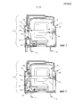
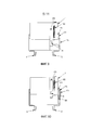
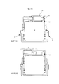
Фиг. 1 - вид в разрезе первого варианта выполнения блока для устройства защиты от перенапряжений в конфигурации, когда температура компонента защиты от перенапряжений ниже критического порога.FIG. 1 is a sectional view of a first embodiment of a block for an overvoltage protection device in a configuration when the temperature of the overvoltage protection component is below a critical threshold.
Фиг. 2 - вид в разрезе первого варианта выполнения блока для устройства защиты от перенапряжений в конфигурации, когда температура компонента защиты от перенапряжений выше критического порога.FIG. 2 is a sectional view of a first embodiment of a block for a surge protection device in a configuration when the temperature of the surge protection component is above a critical threshold.
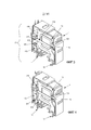
Фиг. 3 - вид в перспективе первого варианта выполнения блока для устройства защиты от перенапряжений в конфигурации, когда температура компонента защиты от перенапряжений ниже критического порога.FIG. 3 is a perspective view of a first embodiment of a block for a surge protection device in a configuration when the temperature of the surge protection component is below a critical threshold.
Фиг. 4 - вид в перспективе первого варианта выполнения блока для устройства защиты от перенапряжений в конфигурации, когда температура компонента защиты от перенапряжений выше критического порога.FIG. 4 is a perspective view of a first embodiment of a block for a surge protection device in a configuration when the temperature of the surge protection component is above a critical threshold.
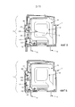
Фиг. 5 - вид в разрезе второго варианта выполнения блока для устройства защиты от перенапряжений в конфигурации, когда температура компонента защиты от перенапряжений ниже критического порога.FIG. 5 is a cross-sectional view of a second embodiment of a unit for a surge protection device in a configuration when the temperature of the surge protection component is below a critical threshold.
Фиг. 6 - вид в разрезе второго варианта выполнения блока для устройства защиты от перенапряжений в конфигурации, когда температура компонента защиты от перенапряжений выше критического порога.FIG. 6 is a cross-sectional view of a second embodiment of a unit for an overvoltage protection device in a configuration when the temperature of the overvoltage protection component is above a critical threshold.
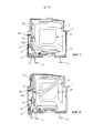
Фиг. 7 - вид в разрезе третьего варианта выполнения блока для устройства защиты от перенапряжений в конфигурации, когда температура компонента защиты от перенапряжений ниже критического порога.FIG. 7 is a sectional view of a third embodiment of a block for a surge protection device in a configuration when the temperature of the surge protection component is below a critical threshold.
Фиг. 8 - вид в разрезе третьего варианта выполнения блока для устройства защиты от перенапряжений в конфигурации, когда температура компонента защиты от перенапряжений выше критического порога.FIG. 8 is a cross-sectional view of a third embodiment of a block for a surge protection device in a configuration when the temperature of the surge protection component is above a critical threshold.
Фиг. 9 - вид в разрезе четвертого варианта выполнения блока для устройства защиты от перенапряжений в конфигурации, когда температура компонента защиты от перенапряжений ниже критического порога.FIG. 9 is a cross-sectional view of a fourth embodiment of a unit for a surge protection device in a configuration when the temperature of the surge protection component is below a critical threshold.
Фиг. 10 - вид в разрезе четвертого варианта выполнения блока для устройства защиты от перенапряжений в конфигурации, когда температура компонента защиты от перенапряжений выше критического порога.FIG. 10 is a sectional view of a fourth embodiment of a block for a surge protection device in a configuration when the temperature of the surge protection component is above a critical threshold.
Фиг. 11 - вид в разрезе пятого варианта выполнения блока для устройства защиты от перенапряжений в конфигурации, когда температура компонента защиты от перенапряжений ниже критического порога.FIG. 11 is a cross-sectional view of a fifth embodiment of a block for a surge protection device in a configuration when the temperature of the surge protection component is below a critical threshold.
Фиг. 12 - вид в разрезе пятого варианта выполнения блока для устройства защиты от перенапряжений в конфигурации, когда температура компонента защиты от перенапряжений выше критического порога.FIG. 12 is a cross-sectional view of a fifth embodiment of a block for a surge protection device in a configuration when the temperature of the surge protection component is above a critical threshold.
Фиг. 13 - вид в разрезе шестого варианта выполнения блока для устройства защиты от перенапряжений в конфигурации, когда температура компонента защиты от перенапряжений ниже критического порога.FIG. 13 is a cross-sectional view of a sixth embodiment of a unit for a surge protection device in a configuration when the temperature of the surge protection component is below a critical threshold.
Фиг. 14 - вид в разрезе шестого варианта выполнения блока для устройства защиты от перенапряжений в конфигурации, когда температура компонента защиты от перенапряжений выше критического порога.FIG. 14 is a cross-sectional view of a sixth embodiment of a block for a surge protection device in a configuration when the temperature of the surge protection component is above a critical threshold.
Фиг. 15 - вид в разрезе седьмого варианта выполнения блока для устройства защиты от перенапряжений в конфигурации, когда температура компонента защиты от перенапряжений ниже критического порога.FIG. 15 is a cross-sectional view of a seventh embodiment of a unit for a surge protection device in a configuration when the temperature of the surge protection component is below a critical threshold.
Фиг. 16 - вид в разрезе седьмого варианта выполнения блока для устройства защиты от перенапряжений в конфигурации, когда температура компонента защиты от перенапряжений выше критического порога.FIG. 16 is a sectional view of a seventh embodiment of a block for a surge protection device in a configuration when the temperature of the surge protection component is above a critical threshold.
Фиг. 17 - вид в разрезе восьмого варианта выполнения блока для устройства защиты от перенапряжений в конфигурации, когда температура компонента защиты от перенапряжений ниже критического порога.FIG. 17 is a cross-sectional view of an eighth embodiment of a unit for a surge protection device in a configuration when the temperature of the surge protection component is below a critical threshold.
Фиг. 18 - вид в разрезе восьмого варианта выполнения блока для устройства защиты от перенапряжений в конфигурации, когда температура компонента защиты от перенапряжений выше критического порога.FIG. 18 is a cross-sectional view of an eighth embodiment of a block for an overvoltage protection device in a configuration when the temperature of the overvoltage protection component is above a critical threshold.
Фиг. 19 - вид в разрезе девятого варианта выполнения блока для устройства защиты от перенапряжений в конфигурации, когда температура компонента защиты от перенапряжений ниже критического порога.FIG. 19 is a cross-sectional view of a ninth embodiment of a block for a surge protection device in a configuration when the temperature of the surge protection component is below a critical threshold.
Фиг. 20 - вид в разрезе девятого варианта выполнения блока для устройства защиты от перенапряжений в конфигурации, когда температура компонента защиты от перенапряжений выше критического порога.FIG. 20 is a sectional view of a ninth embodiment of a block for an overvoltage protection device in a configuration when the temperature of the overvoltage protection component is above a critical threshold.
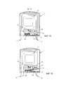
Фиг. 21 - первый вариант выполнения устройства защиты от перенапряжений.FIG. 21 is a first embodiment of a surge protection device.
Фиг. 22 - второй вариант выполнения устройства защиты от перенапряжений.FIG. 22 is a second embodiment of an overvoltage protection device.
Описание предпочтительных вариантов воплощенияDescription of Preferred Embodiments
На фиг. 1-20 представлены девять вариантов выполнения блока 1 для устройства защиты от перенапряжений.In FIG. 1-20, there are nine embodiments of
В этих девяти вариантах блок 1 для устройства защиты от перенапряжений содержит:In these nine embodiments,
- два элемента 11 и 12 электрического соединения;- two
- компонент 13 защиты от перенапряжений, как правило, варистор, электрически связанный с двумя элементами 11 и 12 электрического соединения, температура которого повышается при наличии перенапряжения;-
- блокировочный элемент 15, находящийся в контакте с компонентом 13 защиты от перенапряжений;- a
- механический прерыватель 17, связанный с блокировочным элементом 15, установленный последовательно между одним 11 из двух элементов электрического соединения и компонентом 13 защиты от перенапряжений, при этом блокировочный элемент 15 удерживает прерыватель 17 в замкнутом положении.- a
- Блокировочный элемент 15 и прерыватель 17 являются электрически независимыми, и поэтому блокировочный элемент может не быть электропроводящим. Под понятием «электрически независимый» следует понимать, что блокировочный элемент не является частью контура тока, компонентом которого является прерыватель 17.- The
При перенапряжениях температура компонента 13 защиты от перенапряжений повышается. Повторение во времени перенапряжений приводит к такому повышению температуры, при котором она превышает критический порог. Этот критический порог находится в пределах от 100°С до 240°С и предпочтительно составляет от 120°С до 190°С. Этот порог соответствует температуре, начиная от которой надежность компонента защиты от перенапряжений больше не обеспечивается. Эту температуру определяют в соответствии с требованиями безопасности, содержащимися в действующих нормах безопасности.During overvoltages, the temperature of the
При достижении этого критического порога блокировочный элемент 15, входящий в теплопроводный контакт с оголенной металлической частью электрода 131 компонента 13 защиты от перенапряжений, расплавляется исключительно под действием тепла, передаваемого компонентом 13 защиты от перенапряжений.Upon reaching this critical threshold, the blocking
Блокировочный элемент 15 может представлять собой легкоплавкий припой или пластиковую деталь. Этот блокировочный элемент 15 воспринимает нагрев компонента 13 защиты от перенапряжений и расплавляется при достижении критического температурного порога.The locking
Расплавление блокировочного элемента 15 разблокирует механический прерыватель 17. Если температура компонента защиты от перенапряжений ниже критического порога, механический прерыватель находится в замкнутом положении. Следовательно, блок 1 для устройства защиты от перенапряжений электрически связан с защищаемым устройством.The melting of the locking
Когда температура компонента 13 защиты от перенапряжений превышает критический порог, который соответствует потенциальному повреждению электрического прибора, связанному с нагревом компонента 13 защиты от перенапряжений, расплавление блокировочного элемента освобождает механический прерыватель, который переходит в разомкнутое положение. Таким образом, блок 1 перестает быть электрически связанным с защищаемым устройством.When the temperature of the
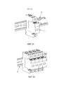
На фиг. 1, 2, 3 и 4 представлен первый вариант выполнения блока 1 для устройства защиты от перенапряжений.In FIG. 1, 2, 3 and 4, a first embodiment of
В этом варианте выполнения механический прерыватель 17 содержит:In this embodiment, the
- две проводящие плоские пружины 171 и 172, соединенные соответственно с первым элементом 11 электрического соединения и с компонентом 13 защиты от перенапряжений,- two conductive
- изолирующую деталь 173, жестко соединенную с приводным элементом 175,- an
- приводной элемент 175, связанный через вырез 177 с подвижной деталью 179,- a
- подвижную деталь 179, связанную с блокировочным элементом 15,a
- первую пружину 181, опирающуюся на изолирующую деталь 173.- the
На фиг. 1 и 3 представлен блок 1, содержащий такой механический прерыватель 17, в случае, когда температура компонента 13 защиты от перенапряжений ниже критического порога и механический прерыватель находится в замкнутом положении. Приводной элемент 175 и первая пружина 181, находящаяся в сжатом состоянии, удерживают изолирующую деталь 173 на расстоянии от двух проводящих плоских пружин 171 и 172, находящихся во взаимном контакте.In FIG. 1 and 3, a
Блокировочный элемент 15 и сжатая вторая пружина 183 удерживают подвижную деталь в так называемом нормальном рабочем положении.The locking
На фиг. 2 и 4 показан блок 1, содержащий такой механический прерыватель 17, в случае, когда температура компонента 13 защиты от перенапряжений становится выше критического порога.In FIG. 2 and 4, a
При повышении температуры компонента 13 защиты от перенапряжений блокировочный элемент 15 расплавился, и под действием второй пружины 183 подвижная деталь поступательно перемещается и высвобождает вырез 177, связывающий ее с приводным элементом 175.As the temperature of the
При этом приводной элемент 175, отошедший из выреза 177 и жестко соединенный с изолирующей деталью 173, удерживаемой сжатой первой пружиной 181, поступательно перемещается в направлении, противоположном двум проводящим плоским пружинам 171 и 172.In this case, the
Это перемещение приводного элементом 175 приводит к поступательному перемещению изолирующей детали 173, жестко соединенной с приводным элементом 175, которая заходит между двумя проводящими плоскими пружинами 171 и 172.This movement of the
Таким образом, электрический контакт между двумя проводящими плоскими пружинами 171 и 172 прерывается, и блок 1 для устройства защиты от перенапряжений, содержащий неисправный компонент 13 защиты от перенапряжений, оказывается изолированным от остальной части электрического прибора.Thus, the electrical contact between the two conductive
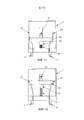
На фиг. 5 и 6 показан второй вариант выполнения блока 1 для устройства защиты от перенапряжений.In FIG. 5 and 6 show a second embodiment of
В этом варианте выполнения механический прерыватель 17 содержит:In this embodiment, the
- две проводящие плоские пружины 171 и 172, соединенные соответственно с первым элементом 11 электрического соединения и с компонентом 13 защиты от перенапряжений,- two conductive
- изолирующую деталь 173, жестко соединенную с приводным элементом 175,- an
- приводной элемент 175, связанный через вырез 177 с подвижной деталью,- a
- подвижную деталь 179, связанную с блокировочным элементом 15,a
- первую пружину 181, опирающуюся на изолирующую деталь 173.- the
В этом втором варианте выполнения подвижная деталь выполнена в виде плоской пружины 1791.In this second embodiment, the movable part is made in the form of a
Блокировочный элемент 15 и прерыватель 17 являются электрически независимыми, и блокировочный элемент может не быть электрическим проводником. The interlocking
На фиг. 5 представлен блок 1, содержащий такой механический прерыватель 17, в случае, когда температура компонента 13 защиты от перенапряжений ниже критического порога и механический прерыватель находится в замкнутом положении.In FIG. 5 shows a
Плоская пружина 1791 удерживается в горизонтальном положении, называемом нормальным рабочим положением, блокировочным элементом 15 и выступом 180, под которым заблокирован один из концов плоской пружины 1791.The
Приводной элемент, связанный с подвижной деталью 1791, удерживает изолирующую деталь 173 на расстоянии от двух проводящих плоских пружин 171 и 172, которые входят во взаимный контакт.The drive element associated with the
На фиг. 6 представлен блок 1, содержащий такой механический прерыватель 17, в случае, когда температура компонента 13 защиты от перенапряжений становится выше критического порога.In FIG. 6 shows a
Под действием нагрева компонента 13 защиты от перенапряжений блокировочный элемент 15 расплавился, и плоская пружина 1791 больше не удерживается блокировочным элементом 15 в горизонтальном положении под выступом 180. Она осуществляет поворотное движение и переходит в вертикальное положение.Under the action of heating the
Приводной элемент 175, связанный с этой плоской пружиной 1791 через вырез 177 и жестко соединенный с изолирующей деталью 173, перемещается при этом поступательным движением в направлении, противоположном двум проводящим плоским пружинам 171 и 172.The
Это перемещение приводного элемента 175 приводит к поступательному перемещению изолирующей детали 173, жестко соединенной с приводным элементом 175, которая заходит двумя проводящими плоскими пружинами 171 и 172.This movement of the
Таким образом, электрический контакт между двумя проводящими плоскими пружинами 171 и 172 прерывается, и блок 1 для устройства защиты от перенапряжений, содержащий неисправный компонент 13 защиты от перенапряжений, оказывается изолированным от остальной части электрического прибора.Thus, the electrical contact between the two conductive
На фиг. 7 и 8 показан третий вариант выполнения блока 1 для устройства защиты от перенапряжений.In FIG. 7 and 8 show a third embodiment of
В этом варианте выполнения механический прерыватель содержит:In this embodiment, the mechanical chopper comprises:
- две проводящие пластины 171 и 172, соединенные соответственно с первым элементом 11 электрического соединения и с компонентом 13 защиты от перенапряжений,- two
- изолирующую деталь 173, жестко соединенную с приводным элементом 175,- an
- приводной элемент 175, связанный через вырез 177 с подвижной деталью,- a
- подвижную деталь, связанную с блокировочным элементом 15,- a movable part associated with the locking
- первую пружину 181, опирающуюся на изолирующую деталь 173.- the
В этом третьем варианте выполнения одна из двух проводящих пластин 172 является плоской пружиной, а подвижная деталь выполнена в виде рычага 1792 с изогнутым плечом.In this third embodiment, one of the two
Блокировочный элемент 15 и прерыватель 17 являются электрически независимыми, и блокировочный элемент может не быть электрическим проводником. The interlocking
На фиг. 7 представлен блок 1, содержащий такой механический прерыватель 17, в случае, когда температура компонента 13 защиты от перенапряжений ниже критического порога и механический прерыватель находится в замкнутом положении.In FIG. 7 shows a
Рычаг 1792 с изогнутым плечом удерживается в так называемом нормальном рабочем положении блокировочным элементом 15 и выступом 180, под которым заблокирован один из концов рычага с изогнутым плечом.The
Приводной элемент 175, связанный с рычагом 1792 с изогнутым плечом через вырез 177, удерживает изолирующую деталь 173 на расстоянии от двух проводящих пластин 171 и 172, которые входят друг с другом в контакт.A
На фиг. 8 показан блок 1, содержащий такой механический прерыватель 17, в случае, когда температура компонента 13 защиты от перенапряжений превышает критический порог.In FIG. 8 shows a
Под действием нагрева компонента 13 защиты от перенапряжений блокировочный элемент 15 расплавился, и рычаг 1792 с изогнутым плечом больше не удерживается блокировочным элементом 15 в горизонтальном положении под выступом 180. Она осуществляет поворотное движение вверх.Under the action of heating the
Приводной элемент 175, связанный с этим рычагом 1792 с изогнутым плечом через вырез 177 и жестко соединенный с изолирующей деталью 173, перемещается при этом поступательным движением в направлении, противоположном двум проводящим пластинам 171 и 172, под действием пружины 181.The
Это перемещение приводного элемента 175 приводит к поступательному перемещению изолирующей детали 173, жестко соединенной с приводным элементом 175, которая оказывается между двумя проводящими пластинами 171 и 172.This movement of the
Таким образом, электрический контакт между двумя проводящими пластинами 171 и 172 прерывается, и блок 1 для устройства защиты от перенапряжений, содержащий неисправный компонент 13 защиты от перенапряжений, оказывается изолированным от остальной части электрического прибора.Thus, the electrical contact between the two
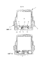
На фиг. 9 и 10 показан четвертый вариант выполнения блока 1 для устройства защиты от перенапряжений.In FIG. 9 and 10 show a fourth embodiment of
В этом варианте выполнения механический прерыватель содержит:In this embodiment, the mechanical chopper comprises:
- две проводящие пластины 171 и 172, соединенные соответственно со вторым элементом 12 электрического соединения и с компонентом защиты от перенапряжений (на фиг. 9 и 10 не показан),- two
- изолирующую деталь 173, жестко соединенную с приводным элементом 175,- an
- приводной элемент 175, связанный с блокировочным элементом 15.- a
Если температура компонента защиты от перенапряжений ниже критического порога, то есть в случае, представленном на фиг. 9, блокировочный элемент 15 удерживает изолирующую деталь 173 через приводной элемент 175 на расстоянии от двух проводящих пластин 171 и 172. Одна из проводящих пластин 172 является плоской пружиной. If the temperature of the surge protection component is below a critical threshold, that is, in the case of FIG. 9, the locking
Как показано на фиг. 10, когда температура компонента защиты от перенапряжений становится выше критического порога, блокировочный элемент 15 расплавляется, что приводит к поступательному перемещению приводного элемента 175 вверх в результате разблокировки и под действием сжатия второй пружины 183. Это поступательное перемещение приводного элемента 175 приводит к поступательному перемещению изолирующей детали 173, жестко соединенной с приводным элементом 175, которая оказывается между двумя проводящими пластинами; при этом проводящая плоская пружина 172 отходит от другой проводящей пластины 171 под действием изолирующей детали. As shown in FIG. 10, when the temperature of the overvoltage protection component rises above a critical threshold, the blocking
Таким образом, электрический контакт между двумя проводящими пластинами 171 и 172 прерывается, и блок 1 для устройства защиты от перенапряжений, содержащий неисправный компонент защиты от перенапряжений, оказывается изолированным от остальной части электрического прибора.Thus, the electrical contact between the two
На фиг. 11 и 12 представлен пятый вариант выполнения блока 1 для устройства защиты от перенапряжений.In FIG. 11 and 12 show a fifth embodiment of
В этом варианте выполнения механический прерыватель содержит:In this embodiment, the mechanical chopper comprises:
- две проводящие пластины 171 и 172; при этом первая проводящая пластина 171 подсоединена между первым элементом 11 электрического соединения и компонентом защиты от перенапряжений (на фиг. 11 и 12 не показан); вторая проводящая пластина 172 подсоединена между вторым элементом 12 электрического соединения и компонентом защиты от перенапряжений,- two
- изолирующую деталь 173, жестко соединенную с приводным элементом 175,- an
- приводной элемент 175, связанный с блокировочным элементом 15.- a
Если температура компонента защиты от перенапряжений ниже критического порога, то есть в случае, представленном на фиг.11, блокировочный элемент 15 удерживает изолирующую деталь 173 через приводной элемент 175 на расстоянии от двух проводящих пластин 171 и 172. If the temperature of the surge protection component is below a critical threshold, that is, in the case of FIG. 11, the blocking
Как показано на фиг. 12, когда температура компонента защиты от перенапряжений становится выше критического порога, блокировочный элемент 15 плавится, что приводит к поступательному перемещению приводного элемента 175 вверх в результате разблокировки и под действием растяжения первой пружины 181. Это поступательное перемещение приводного элемента 175 приводит к поступательному перемещению изолирующей детали 173, жестко соединенной с приводным элементом 175, которая оказывается между двумя электрическими контактами между первой проводящей пластиной 171 и первым элементом 11 электрического соединения и между второй проводящей пластиной 172 и вторым элементом 12 электрического соединения.As shown in FIG. 12, when the temperature of the overvoltage protection component rises above a critical threshold, the blocking
Таким образом, электрический контакт оказывается разомкнутым, и блок 1 для устройства защиты от перенапряжений, содержащий неисправный компонент защиты от перенапряжений, оказывается изолированным от остальной части электрического прибора.Thus, the electrical contact is open, and the
На фиг. 13 и 14 представлен шестой вариант выполнения блока 1 для устройства защиты от перенапряжений.In FIG. 13 and 14 show a sixth embodiment of
В этом варианте выполнения механический прерыватель содержит:In this embodiment, the mechanical chopper comprises:
- две проводящие пластины 171 и 172, соединенные соответственно с вторым элементом 12 электрического соединения и с компонентом защиты от перенапряжений (на фиг. 13 и 14 не показан),- two
- изолирующую деталь 173, связанную с подвижной деталью 179 через вырез 177,- an
- подвижную деталь 179, связанную с блокировочным элементом 15.- a
Если температура компонента защиты от перенапряжений ниже критического порога, то есть в случае, представленном на фиг.13, блокировочный элемент 15 удерживает подвижную деталь 179, содержащую вырез 177. При помощи этого выреза 177 изолирующая деталь 173 удерживается на расстоянии от двух проводящих пластин 171 и 172. Одна из двух проводящих пластин 172 является плоской пружиной.If the temperature of the surge protection component is below a critical threshold, that is, in the case of FIG. 13, the locking
Как показано на фиг. 14, когда температура компонента защиты от перенапряжений становится выше критического порога, блокировочный элемент 15 плавится, что приводит к поступательному перемещению подвижной детали 179 и к высвобождению изолирующей детали 173 от выреза 177. Вышедшая таким образом из выреза изолирующая деталь 173 перемещается поступательным движением вверх под действием растяжения первой пружины 181. За счет этого поступательного движения изолирующая деталь 173 оказывается между двумя проводящими пластинами 171 и 172; под действием изолирующей детали проводящая плоская пружина 172 отходит от другой проводящей пластины 171.As shown in FIG. 14, when the temperature of the overvoltage protection component rises above a critical threshold, the blocking
Таким образом, электрический контакт оказывается разомкнутым, и блок 1 для устройства защиты от перенапряжений, содержащий неисправный компонент защиты от перенапряжений, оказывается изолированным от остальной части электрического прибора.Thus, the electrical contact is open, and the
На фиг. 15 и 16 представлен седьмой вариант выполнения блока 1 для устройства защиты от перенапряжений.In FIG. 15 and 16 show a seventh embodiment of
В этом варианте выполнения механический прерыватель содержит:In this embodiment, the mechanical chopper comprises:
- две проводящие пластины 171 и 172, соединенные соответственно с вторым элементом 12 электрического соединения и с компонентом 13 защиты от перенапряжений,- two
- изолирующую деталь 173, связанную с подвижной деталью 179 через вырез 177,- an
- подвижную деталь 179, связанную с блокировочным элементом 15.- a
Если температура компонента защиты от перенапряжений ниже критического порога, то есть в случае, представленном на фиг.15, блокировочный элемент 15 удерживает подвижную деталь 179, содержащую вырез 177. При помощи этого выреза 177 изолирующая деталь 173 удерживается на расстоянии от двух проводящих пластин 171 и 172. Обе проводящие пластины 171 и 172 являются плоскими пружинами.If the temperature of the surge protection component is below a critical threshold, that is, in the case of FIG. 15, the blocking
Как показано на фиг. 16, когда температура компонента 13 защиты от перенапряжений превышает критический порог, блокировочный элемент 15 расплавляется, что приводит к поступательному перемещению вверх подвижной детали 179 и к высвобождению изолирующей детали 173 из выреза 177. Вышедшая таким образом из выреза изолирующая деталь 173 перемещается горизонтальным поступательным движением под действием растяжения первой пружины 181. За счет этого поступательного движения изолирующая деталь 173 оказывается между двумя проводящими пластинами 171 и 172, которые, учитывая их упругость, отходят друг от друга под действием изолирующей детали 173.As shown in FIG. 16, when the temperature of the
Таким образом, электрический контакт оказывается разомкнутым, и блок 1 для устройства защиты от перенапряжений, содержащий неисправный компонент защиты от перенапряжений, оказывается изолированным от остальной части электрического прибора.Thus, the electrical contact is open, and the
На фиг. 17 и 18 представлен восьмой вариант выполнения блока 1 для устройства защиты от перенапряжений.In FIG. 17 and 18 show an eighth embodiment of
В этом варианте выполнения механический прерыватель содержит:In this embodiment, the mechanical chopper comprises:
- две проводящие пластины 171 и 172, соединенные соответственно с первым элементом 11 электрического соединения и с компонентом 13 защиты от перенапряжений,- two
- изолирующую деталь 173, связанную с подвижной деталью 179 через вырез 177,- an
- подвижную деталь 179, связанную с блокировочным элементом 15.- a
Если температура компонента защиты от перенапряжений ниже критического порога, то есть в случае, представленном на фиг.17, блокировочный элемент 15 удерживает подвижную деталь 179, содержащую вырез 177. При помощи этого выреза 177 изолирующая деталь 173 удерживается на расстоянии от двух проводящих пластин 171 и 172. Проводящая пластина 172 является плоской пружиной.If the temperature of the surge protection component is below a critical threshold, that is, in the case of FIG. 17, the locking
Как показано на фиг. 18, когда температура компонента 13 защиты от перенапряжений становится выше критического порога, блокировочный элемент 15 плавится, что приводит к повороту вниз подвижной детали 179 и к высвобождению изолирующей детали 173 из выреза 177. Вышедшая таким образом из выреза изолирующая деталь 173 перемещается горизонтальным поступательным движением под действием растяжения первой пружины 181. За счет этого поступательного движения изолирующая деталь 173 заходит между двумя проводящими пластинами 171 и 172, которые отходят друг от друга под действием изолирующей детали 173.As shown in FIG. 18, when the temperature of the
Таким образом, электрический контакт оказывается разомкнутым, и блок 1 для устройства защиты от перенапряжений, содержащий неисправный компонент защиты от перенапряжений, оказывается изолированным от остальной части электрического прибора.Thus, the electrical contact is open, and the
На фиг. 19 и 20 представлен девятый вариант выполнения блока 1 для устройства защиты от перенапряжений.In FIG. 19 and 20 show a ninth embodiment of
В этом варианте выполнения механический прерыватель содержит:In this embodiment, the mechanical chopper comprises:
- две проводящие пластины 171 и 172, соединенные соответственно с первым элементом 11 электрического соединения и с компонентом 13 защиты от перенапряжений,- two
- подвижную изолирующую деталь 173, связанную с варистором 13 через термический путь 131 и блокировочный элемент 15.a movable insulating
Если температура компонента защиты от перенапряжений ниже критического порога, то есть в случае, представленном на фиг.19, блокировочный элемент 15 удерживает подвижную деталь 173. Изолирующая деталь 173 удерживается на расстоянии от двух проводящих пластин 171 и 172. Проводящая пластина 171 является плоской пружиной.If the temperature of the surge protection component is below a critical threshold, that is, in the case of FIG. 19, the blocking
Как показано на фиг. 20, когда температура компонента 13 защиты от перенапряжений становится выше критического порога, блокировочный элемент 15 плавится, что приводит к поступательному горизонтальному перемещению изолирующей детали 173 под действием растяжения первой пружины 181. За счет этого поступательного движения эта изолирующая деталь оказывается между двумя проводящими пластинами 171 и 172, которые отходят друг от друга под действием изолирующей детали 173.As shown in FIG. 20, when the temperature of the
Таким образом, электрический контакт оказывается разомкнутым, и блок 1 для устройства защиты от перенапряжений, содержащий неисправный компонент защиты от перенапряжений, оказывается изолированным от остальной части электрического прибора.Thus, the electrical contact is open, and the
Объектом изобретения является также устройство защиты от перенапряжений. На фиг. 21 и 22 представлены два варианта выполнения устройства защиты от перенапряжений.A subject of the invention is also a surge protection device. In FIG. 21 and 22 show two embodiments of a surge protection device.
На фиг. 21 показан первый вариант выполнения устройства защиты от перенапряжений, содержащего:In FIG. 21 shows a first embodiment of a surge protection device comprising:
- блок 1 защиты от перенапряжений согласно одному из описанных выше вариантов выполнения,-
- цоколь, закрепленный на направляющей 23.- base mounted on the
Подключение устройства защиты от перенапряжений происходит во время посадки блока 1 защиты от перенапряжений на цоколь. Это подключение осуществляют посредством электрического соединения двух элементов электрического соединения и блока 1 с цоколем. Таким образом, устройство 2 защиты от перенапряжений оказывается электрически связанным с защищаемым электрическим прибором или оборудованием.The connection of the surge protection device occurs during the
Когда температура компонента защиты от перенапряжений достигает заранее определенного критического порога, прерывание электрического контакта между проводящими пластинами изолирует устройство защиты от перенапряжений от защищаемого электрического прибора или оборудования.When the temperature of the surge protection component reaches a predetermined critical threshold, interruption of the electrical contact between the conductive plates isolates the surge protection device from the protected electrical appliance or equipment.
На фиг. 22 показан второй вариант выполнения устройства защиты от перенапряжений, содержащего:In FIG. 22 shows a second embodiment of an overvoltage protection device, comprising:
- множество блоков для устройства защиты от перенапряжений согласно одному из описанных выше вариантов выполнения,- a plurality of blocks for an overvoltage protection device according to one of the embodiments described above,
- множество цоколей, закрепленных на направляющей 23.- many socles mounted on the
Подключение устройства защиты от перенапряжений происходит во время посадки каждого из упомянутых блоков защиты от перенапряжений на каждый из соответствующих упомянутых цоколей. The connection of the surge protection device occurs during the landing of each of the above-mentioned surge protection units on each of the respective mentioned socles.
Это подключение осуществляют посредством электрического соединения двух элементов электрического соединения и каждого блока с соответствующим цоколем. Таким образом, устройство защиты от перенапряжений оказывается электрически связанным с защищаемым электрическим прибором или оборудованием.This connection is made by electrically connecting two elements of the electrical connection and each unit with a corresponding base. Thus, the surge protection device is electrically connected to the protected electrical appliance or equipment.
Когда температура компонента защиты от перенапряжений достигает заранее определенного критического порога, прерывание электрического контакта между проводящими пластинами каждого из упомянутых блоков изолирует устройство защиты от перенапряжений от защищаемого электрического прибора или оборудования.When the temperature of the surge protection component reaches a predetermined critical threshold, interruption of the electrical contact between the conductive plates of each of said blocks isolates the surge protection device from the protected electrical appliance or equipment.
Изобретение было подробно описано и проиллюстрировано на чертежах и в предшествующем описании. Это описание представлено в качестве примера и не ограничивает изобретение своим содержанием. Возможны многочисленные варианты выполнения.The invention has been described in detail and illustrated in the drawings and in the foregoing description. This description is provided as an example and does not limit the invention to its content. Numerous embodiments are possible.
В формуле изобретения слово «содержит» не исключает наличия других элементов, и единственное число не исключает множественности.In the claims, the word “contains” does not exclude the presence of other elements, and the singular does not exclude plurality.
Claims (25)
Applications Claiming Priority (2)
| Application Number | Priority Date | Filing Date | Title |
|---|---|---|---|
| FR1161296A FR2984006B1 (en) | 2011-12-07 | 2011-12-07 | HOUSING FOR OVERVOLTAGE PROTECTION DEVICE AND ASSOCIATED OVERVOLTAGE PROTECTION DEVICE. |
| FR1161296 | 2011-12-07 |
Publications (2)
| Publication Number | Publication Date |
|---|---|
| RU2012152603A RU2012152603A (en) | 2014-06-20 |
| RU2623503C2 true RU2623503C2 (en) | 2017-06-27 |
Family
ID=47257708
Family Applications (1)
| Application Number | Title | Priority Date | Filing Date |
|---|---|---|---|
| RU2012152603A RU2623503C2 (en) | 2011-12-07 | 2012-12-06 | Unit for overvoltage protection device and relevant overvoltage protection device |
Country Status (8)
| Country | Link |
|---|---|
| EP (1) | EP2602805B1 (en) |
| CN (1) | CN103151226B (en) |
| BR (1) | BR102012031212A2 (en) |
| ES (1) | ES2607608T3 (en) |
| FR (1) | FR2984006B1 (en) |
| PL (1) | PL2602805T3 (en) |
| RU (1) | RU2623503C2 (en) |
| SI (1) | SI2602805T1 (en) |
Cited By (1)
| Publication number | Priority date | Publication date | Assignee | Title |
|---|---|---|---|---|
| RU211595U1 (en) * | 2022-01-28 | 2022-06-15 | Общество с ограниченной ответственностью "РАЗТЕХ" (ООО "РАЗТЕХ") | Single-phase power circuit breaker |
Families Citing this family (9)
| Publication number | Priority date | Publication date | Assignee | Title |
|---|---|---|---|---|
| DE102014008366B3 (en) * | 2014-06-04 | 2015-10-22 | Dehn + Söhne Gmbh + Co. Kg | Device for thermal tripping or disconnection of an overvoltage protection device |
| CZ309285B6 (en) * | 2014-06-27 | 2022-07-20 | KIWA sk, s.r.o | Surge protection equipment |
| DE102015000329B3 (en) * | 2015-01-09 | 2016-05-19 | DEHN + SÖHNE GmbH + Co. KG. | Surge protection device with mechanical disconnection device activated in thermal overload |
| BE1025343B1 (en) * | 2017-06-22 | 2019-02-04 | Phoenix Contact Gmbh & Co. Kg | Overvoltage protection device with connection elements and method for producing the same |
| CN108429235B (en) * | 2018-04-28 | 2024-02-02 | 深圳市海鹏信电子股份有限公司 | Surge protection device |
| DE102019110745B3 (en) * | 2019-04-25 | 2020-10-08 | Dehn Se + Co Kg | Surge protection device and modular surge protection system |
| FR3107780B1 (en) | 2020-02-27 | 2022-03-11 | Legrand France | Electrical device against transient overvoltages and a thermal runaway detection varistor device |
| FR3107781B1 (en) | 2020-02-27 | 2023-06-30 | Legrand France | Electrical device against transient overvoltages and a thermal runaway detection varistor device |
| DE202020000983U1 (en) * | 2020-03-11 | 2020-03-26 | Abn Gmbh | Receiving device for a surge protection unit |
Citations (4)
| Publication number | Priority date | Publication date | Assignee | Title |
|---|---|---|---|---|
| EP1826795A1 (en) * | 2006-02-24 | 2007-08-29 | ABB France | Device for protecting against overvoltage with simplified display system and corresponding manufacturing method |
| RU2321930C2 (en) * | 2002-12-10 | 2008-04-10 | Суль Протексьон Сюртансьон | Overvoltage protective device |
| DE202009013505U1 (en) * | 2008-12-11 | 2010-04-15 | Phoenix Contact Gmbh & Co. Kg | Snubber |
| RU2407087C2 (en) * | 2006-02-13 | 2010-12-20 | Ден + Зёне Гмбх + Ко. Кг | Discharge arrester for overvoltage protection, comprising at least one discharge element, for instance varistor |
Family Cites Families (6)
| Publication number | Priority date | Publication date | Assignee | Title |
|---|---|---|---|---|
| DE10001632A1 (en) * | 2000-01-17 | 2001-08-02 | Harting Automotive Gmbh & Co | Circuit breaker has displacement element adjustable relative to two conductors and separating element that separates conductors when displacement element in separation position |
| ES2399966T3 (en) * | 2004-10-08 | 2013-04-04 | Abb France | Surge protection device provided with arc cutting means and corresponding procedure |
| FR2877154B1 (en) * | 2004-10-22 | 2006-12-22 | Legrand Sa | IMPROVED DEVICE FOR PROTECTING ELECTRICAL DEVICES AGAINST OVERVOLTAGES |
| DE102007006617B3 (en) * | 2007-02-06 | 2008-09-04 | Phoenix Contact Gmbh & Co. Kg | Overvoltage protection element has housing, with two overvoltage-limiting component arranged in housing, where control rod is shifted to distance, even if slide valve is passed from position to another position |
| FR2925216B1 (en) | 2007-12-18 | 2010-04-23 | Abb France | OVERVOLTAGE PROTECTION DEVICE HAVING A DISCONNECTION AUXILIARY |
| CN201450331U (en) * | 2009-07-27 | 2010-05-05 | 佛山市浦斯电子有限公司 | Surge protective device provided with thermal protective device |
-
2011
- 2011-12-07 FR FR1161296A patent/FR2984006B1/en active Active
-
2012
- 2012-12-05 PL PL12195643T patent/PL2602805T3/en unknown
- 2012-12-05 ES ES12195643.7T patent/ES2607608T3/en active Active
- 2012-12-05 EP EP12195643.7A patent/EP2602805B1/en active Active
- 2012-12-05 SI SI201230798A patent/SI2602805T1/en unknown
- 2012-12-06 RU RU2012152603A patent/RU2623503C2/en active
- 2012-12-07 CN CN201210524157.5A patent/CN103151226B/en active Active
- 2012-12-07 BR BR102012031212A patent/BR102012031212A2/en not_active Application Discontinuation
Patent Citations (4)
| Publication number | Priority date | Publication date | Assignee | Title |
|---|---|---|---|---|
| RU2321930C2 (en) * | 2002-12-10 | 2008-04-10 | Суль Протексьон Сюртансьон | Overvoltage protective device |
| RU2407087C2 (en) * | 2006-02-13 | 2010-12-20 | Ден + Зёне Гмбх + Ко. Кг | Discharge arrester for overvoltage protection, comprising at least one discharge element, for instance varistor |
| EP1826795A1 (en) * | 2006-02-24 | 2007-08-29 | ABB France | Device for protecting against overvoltage with simplified display system and corresponding manufacturing method |
| DE202009013505U1 (en) * | 2008-12-11 | 2010-04-15 | Phoenix Contact Gmbh & Co. Kg | Snubber |
Cited By (1)
| Publication number | Priority date | Publication date | Assignee | Title |
|---|---|---|---|---|
| RU211595U1 (en) * | 2022-01-28 | 2022-06-15 | Общество с ограниченной ответственностью "РАЗТЕХ" (ООО "РАЗТЕХ") | Single-phase power circuit breaker |
Also Published As
| Publication number | Publication date |
|---|---|
| CN103151226A (en) | 2013-06-12 |
| PL2602805T3 (en) | 2017-08-31 |
| ES2607608T3 (en) | 2017-04-03 |
| BR102012031212A2 (en) | 2015-01-27 |
| FR2984006A1 (en) | 2013-06-14 |
| CN103151226B (en) | 2016-02-03 |
| SI2602805T1 (en) | 2017-02-28 |
| RU2012152603A (en) | 2014-06-20 |
| EP2602805A1 (en) | 2013-06-12 |
| FR2984006B1 (en) | 2017-05-12 |
| EP2602805B1 (en) | 2016-11-02 |
Similar Documents
| Publication | Publication Date | Title |
|---|---|---|
| RU2623503C2 (en) | Unit for overvoltage protection device and relevant overvoltage protection device | |
| US9172236B2 (en) | Overvoltage protection device having at least one surge arrester | |
| EP3460938B1 (en) | Arc-preventing fast-breaking surge protection apparatus | |
| CA2785605C (en) | Switchgear unit for switching high dc voltages | |
| US20170110226A1 (en) | Surge protection device, comprising at least one surge arrester and one short-circuit switching device which is connected in parallel with the surge arrester, can be thermally tripped and is spring-pretensioned | |
| CN102270554B (en) | Mold cased circuit brreaker | |
| RU2321930C2 (en) | Overvoltage protective device | |
| CN117321717A (en) | Electrical protective equipment and systems with integrated cut-out modules | |
| US20080186643A1 (en) | Voltage surge protection device with a movable contact comprising selective disconnection means against short-circuits | |
| US20160240290A1 (en) | Surge protection device, comprising at least one surge arrester and one thermally trippable switching device connected in series with the surge arrester | |
| CN107818891B (en) | Switchgear with means for reliably indicating the switch position when the contacts are welded | |
| KR20180027098A (en) | Arc extinguishing structures | |
| CN101277013B (en) | Device for protecting against voltage surges with a mobile electrode with system for unlocking the disconnection device | |
| CN115298789B (en) | Compact, operator-independent snap-action switching mechanism and electromechanical protective switchgear | |
| CN103931064B (en) | Method and circuit arrangement for breaking an electrical connection between two connection points | |
| US9659726B2 (en) | Switching device with improved tripping action in the event of a short circuit | |
| CN113113273B (en) | A signal SPD tripping mechanism | |
| CN220491819U (en) | SPD tripping protection assembly | |
| CN222654827U (en) | Gap module and combined gap type surge protector | |
| KR200437071Y1 (en) | Circuit breaker | |
| CN117080028B (en) | Surge suppression device with arc extinguishing function | |
| KR102003329B1 (en) | Circuit breaker having improved structure for preventing internal short | |
| CN120977833A (en) | An integrated circuit protector with uninterrupted protection zones | |
| CN120977827A (en) | A fusion switch | |
| KR102003328B1 (en) | Circuit breaker having improved trip bar structure |