RU2620770C2 - Device for direct active projection - Google Patents
Device for direct active projection Download PDFInfo
- Publication number
- RU2620770C2 RU2620770C2 RU2014133096A RU2014133096A RU2620770C2 RU 2620770 C2 RU2620770 C2 RU 2620770C2 RU 2014133096 A RU2014133096 A RU 2014133096A RU 2014133096 A RU2014133096 A RU 2014133096A RU 2620770 C2 RU2620770 C2 RU 2620770C2
- Authority
- RU
- Russia
- Prior art keywords
- light
- lens
- level
- intensity
- flat
- Prior art date
Links
Images
Classifications
-
- H—ELECTRICITY
- H05—ELECTRIC TECHNIQUES NOT OTHERWISE PROVIDED FOR
- H05B—ELECTRIC HEATING; ELECTRIC LIGHT SOURCES NOT OTHERWISE PROVIDED FOR; CIRCUIT ARRANGEMENTS FOR ELECTRIC LIGHT SOURCES, IN GENERAL
- H05B47/00—Circuit arrangements for operating light sources in general, i.e. where the type of light source is not relevant
- H05B47/10—Controlling the light source
-
- G—PHYSICS
- G08—SIGNALLING
- G08G—TRAFFIC CONTROL SYSTEMS
- G08G1/00—Traffic control systems for road vehicles
- G08G1/09—Arrangements for giving variable traffic instructions
- G08G1/095—Traffic lights
-
- G—PHYSICS
- G09—EDUCATION; CRYPTOGRAPHY; DISPLAY; ADVERTISING; SEALS
- G09F—DISPLAYING; ADVERTISING; SIGNS; LABELS OR NAME-PLATES; SEALS
- G09F13/00—Illuminated signs; Luminous advertising
- G09F13/04—Signs, boards or panels, illuminated from behind the insignia
-
- G—PHYSICS
- G02—OPTICS
- G02F—OPTICAL DEVICES OR ARRANGEMENTS FOR THE CONTROL OF LIGHT BY MODIFICATION OF THE OPTICAL PROPERTIES OF THE MEDIA OF THE ELEMENTS INVOLVED THEREIN; NON-LINEAR OPTICS; FREQUENCY-CHANGING OF LIGHT; OPTICAL LOGIC ELEMENTS; OPTICAL ANALOGUE/DIGITAL CONVERTERS
- G02F1/00—Devices or arrangements for the control of the intensity, colour, phase, polarisation or direction of light arriving from an independent light source, e.g. switching, gating or modulating; Non-linear optics
- G02F1/01—Devices or arrangements for the control of the intensity, colour, phase, polarisation or direction of light arriving from an independent light source, e.g. switching, gating or modulating; Non-linear optics for the control of the intensity, phase, polarisation or colour
- G02F1/13—Devices or arrangements for the control of the intensity, colour, phase, polarisation or direction of light arriving from an independent light source, e.g. switching, gating or modulating; Non-linear optics for the control of the intensity, phase, polarisation or colour based on liquid crystals, e.g. single liquid crystal display cells
-
- G—PHYSICS
- G08—SIGNALLING
- G08G—TRAFFIC CONTROL SYSTEMS
- G08G1/00—Traffic control systems for road vehicles
- G08G1/09—Arrangements for giving variable traffic instructions
- G08G1/091—Traffic information broadcasting
Landscapes
- Physics & Mathematics (AREA)
- General Physics & Mathematics (AREA)
- Engineering & Computer Science (AREA)
- Theoretical Computer Science (AREA)
- Circuit Arrangement For Electric Light Sources In General (AREA)
- Illuminated Signs And Luminous Advertising (AREA)
- Road Signs Or Road Markings (AREA)
- Liquid Crystal (AREA)
- Overhead Projectors And Projection Screens (AREA)
- Control Of Indicators Other Than Cathode Ray Tubes (AREA)
Abstract
Description
Ссылка на родственную заявкуLink to a related application
По настоящей заявке испрашивается приоритет в соответствии с предварительной заявкой США №61/595261, поданной 6 февраля 2012 г., все содержание которой включено в настоящую заявку посредством ссылки.This application claims priority in accordance with provisional application US No. 61/595261, filed February 6, 2012, the entire contents of which are incorporated into this application by reference.
Область техникиTechnical field
Настоящее изобретение относится к области информационных указателей, а более конкретно - к области активных указателей, способных проецировать динамическую информацию на движущегося наблюдателя.The present invention relates to the field of information pointers, and more particularly to the field of active pointers capable of projecting dynamic information onto a moving observer.
Уровень техникиState of the art
На автодорогах и улицах присутствуют многочисленные информационные указатели, содержащие самую разнообразную информацию. В состав такой информации могут входить названия улиц/выездов, указания на расстояния и сведения о маршруте до точек назначения, сообщения о состоянии дорожного движения, правила дорожной безопасности (в том числе информация об ограничениях скорости, необходимости смены полос движения и т.д.), а также рекламная и другая информация.On roads and streets there are numerous information signs containing a wide variety of information. Such information may include street / exit names, directions to distances and route information to destination points, traffic status messages, road safety rules (including information about speed limits, the need to change lanes, etc.) , as well as advertising and other information.
Некоторые дорожные указатели представляют собой указатели с активным отображением, например, предупреждающие о заторах, ремонтных работах и авариях, имеющихся далее по ходу движения, с возможностью активного изменения и/или обновления отображаемой информации. Отображаемая информация может быть запрограммирована заранее и отображена без учета каких бы то ни было данных обратной связи, сообщающих о наличии на дороге транспортных средств, водители которых могут видеть и использовать такую информацию. Это может приводить к неоправданному энергопотреблению. Кроме того, такие указатели часто используют для проецирования информации ламбертовскую или другую аналогичную диаграмму направленности с большим телесным углом, что подразумевает неоправданное проецирование на обочины дороги или в вертикальном направлении, где потребность в таком проецировании отсутствует, так как в этих направлениях отсутствуют водители или пассажиры транспортных средств, способные использовать данную информацию. Такое ненаправленное проецирование может приводить к дополнительным непроизводительным расходам энергии.Some road signs are indicators with an active display, for example, warning of congestion, repair work and accidents, further down the road, with the ability to actively change and / or update the displayed information. The displayed information can be programmed in advance and displayed without taking into account any feedback data reporting the presence on the road of vehicles whose drivers can see and use such information. This can lead to unnecessary power consumption. In addition, such pointers often use a Lambert or other similar radiation pattern with a large solid angle to project information, which implies unjustified projection onto roadsides or in a vertical direction, where there is no need for such projection, since there are no drivers or passengers of vehicles in these directions means capable of using this information. Such omnidirectional projection can lead to additional unproductive energy costs.
Таким образом, существует потребность в активных средствах сигнализации, способных проецировать динамически изменяющуюся информацию в направлении приближающихся транспортных средств только в случае обнаружения таковых.Thus, there is a need for active signaling devices capable of projecting dynamically changing information in the direction of approaching vehicles only if they are detected.
Раскрытие изобретенияDisclosure of invention
Устройства и способы по настоящему изобретению обеспечивают устранение затруднений и недостатков, свойственных известным системам, следующим образом.The devices and methods of the present invention eliminate the difficulties and disadvantages inherent in known systems, as follows.
В соответствии с изобретением предлагается активный указатель, содержащий средства для определения местоположения одного или нескольких приближающихся транспортных средств, плоские средства для отображения неизменного или изменяющегося изображения в соответствии с приближающимся транспортным средством и средства активного проецирования отображаемого изображения, по существу, в направлении транспортного средства в соответствии с определенным местоположением.In accordance with the invention, there is provided an active indicator comprising means for determining the location of one or more approaching vehicles, flat means for displaying a constant or changing image in accordance with an approaching vehicle, and means for actively projecting a displayed image substantially in the direction of the vehicle in accordance with a specific location.
В соответствии с одним из аспектов изобретения предлагается устройство для направленного активного проецирования, содержащее плоские средства отображения для отображения информационного изображения, причем плоские средства содержат прозрачные участки. Устройство для проецирования также содержит фокусирующие средства, расположенные вблизи плоских средств отображения. Кроме того, устройство для проецирования содержит несколько светоизлучающих средств, расположенных в виде матрицы в фокальной плоскости фокусирующих средств.In accordance with one aspect of the invention, there is provided a device for directional active projection comprising flat display means for displaying an information image, the flat means comprising transparent portions. The projection device also comprises focusing means located close to the flat display means. In addition, the projection device comprises several light emitting means arranged in a matrix in the focal plane of the focusing means.
В соответствии с другим аспектом изобретения предлагается способ управления устройством для активного направленного проецирования света. Способ включает в себя инициализацию нескольких источников света, расположенных в фокальной плоскости линзы в выключенном состоянии. Способ также включает в себя определение уровня интенсивности падающего света при помощи датчиков, связанных с каждым из источников света. Способ дополнительно включает в себя выявление превышения уровнем интенсивности падающего света порогового уровня при помощи схемы, связывающей каждый из источников света с соответствующим ему датчиком. Кроме того, способ включает в себя включение источника света для освещения линзы в случае превышения уровнем интенсивности падающего света, определенным соответствующим датчиком, порогового уровня. Наконец, способ включает в себя выключение источника света в случае отсутствия превышения уровнем интенсивности падающего света, определенным соответствующим датчиком, порогового уровня.In accordance with another aspect of the invention, there is provided a method of controlling a device for actively guiding light projection. The method includes initializing several light sources located in the focal plane of the lens in the off state. The method also includes determining the level of intensity of the incident light using sensors associated with each of the light sources. The method further includes detecting that the incident light level exceeds the threshold level using a circuit connecting each of the light sources with a corresponding sensor. In addition, the method includes turning on a light source to illuminate the lens if the incident light level determined by the corresponding sensor exceeds the threshold level. Finally, the method includes turning off the light source in the absence of exceeding the level of intensity of the incident light determined by the corresponding sensor threshold level.
В соответствии с дальнейшим аспектом изобретения предлагается устройство для направленного активного проецирования, содержащее плоский экран для отображения информационного изображения. Плоский экран содержит участки, допускающие прохождение света, и участки, блокирующие прохождение света. Устройство также содержит линзу, расположенную вблизи плоского экрана. Устройство дополнительно содержит несколько источников света, расположенных в виде матрицы в фокальной плоскости линзы.In accordance with a further aspect of the invention, there is provided a device for directional active projection comprising a flat screen for displaying an information image. The flat screen contains areas that allow the passage of light, and areas that block the passage of light. The device also contains a lens located near the flat screen. The device further comprises several light sources arranged in a matrix in the focal plane of the lens.
Следует понимать, что в представленное в настоящем описании решение допускает и другие варианты осуществления, причем некоторые его элементы могут быть изменены различными образами, не выходя за рамки объема настоящего изобретения. Соответственно, приведенные чертежи и описание следует рассматривать как иллюстрирующие и не накладывающие каких-либо ограничений.It should be understood that in the solution presented in the present description there are other options for implementation, and some of its elements can be changed in different ways, without going beyond the scope of the present invention. Accordingly, the drawings and description should be considered as illustrative and not imposing any restrictions.
Краткое описание чертежейBrief Description of the Drawings
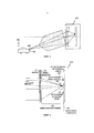
На фиг. 1 представлены общие черты, свойственные возможным вариантам осуществления указателя, выполненного с возможностью проецирования информации в направлении движущегося транспортного средства, по настоящему изобретению.In FIG. 1 shows the general features inherent in possible embodiments of a pointer adapted to project information in the direction of a moving vehicle of the present invention.
Фиг. 2 иллюстрирует первый вариант осуществления устройства для направленного аксиального проецирования информации от указателя по настоящему изобретению.FIG. 2 illustrates a first embodiment of an apparatus for guiding axially projecting information from a pointer of the present invention.
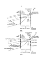
Фиг. 3 иллюстрирует второй вариант осуществления устройства для направленного неаксиального проецирования информации от указателя по настоящему изобретению.FIG. 3 illustrates a second embodiment of a device for guiding non-axially projecting information from a pointer of the present invention.
Фиг. 4 иллюстрирует третий вариант осуществления устройства для направленного неаксиального проецирования информации от указателя по настоящему изобретению.FIG. 4 illustrates a third embodiment of a device for directing non-axial projection of information from a pointer of the present invention.
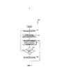
Фиг. 5 иллюстрирует способ направленного проецирования информации от указателя в направлении одного или нескольких транспортных средств по настоящему изобретению.FIG. 5 illustrates a method for directionally projecting information from a pointer in the direction of one or more vehicles of the present invention.
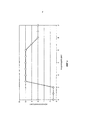
На фиг. 6 представлен пример зависимости светимости программируемого указателя по настоящему изобретению от интенсивности падающего света от одного или нескольких приближающихся транспортных средств.In FIG. 6 shows an example of the dependence of the luminosity of the programmable pointer of the present invention on the intensity of the incident light from one or more approaching vehicles.
Осуществление изобретенияThe implementation of the invention
Приведенное ниже подробное описание, содержащее ссылки на прилагаемые чертежи, следует рассматривать как описание различных конфигураций, но не описание единственных конфигураций, в которых могут быть осуществлены описываемые в настоящем документе принципы. Подробное описание содержит конкретные элементы, приведенные для лучшего понимания различных принципов. Однако специалистам в данной области должно быть очевидно, что такие принципы могут быть осуществлены на практике и без использования этих конкретных элементов.The following detailed description, which contains links to the accompanying drawings, should be considered as a description of the various configurations, but not a description of the only configurations in which the principles described herein can be implemented. The detailed description contains specific elements for a better understanding of the various principles. However, it should be apparent to those skilled in the art that such principles can be practiced without the use of these specific elements.
В соответствии с настоящим изобретением предлагается устройство для направленного активного проецирования, содержащее плоский экран для отображения информации или информационного изображения, один или несколько фокусирующих элементов или линз, расположенных вплотную к плоскому экрану или вблизи него, и один или несколько источников света. В некоторых вариантах осуществления источники света могут быть расположены в фокальной плоскости фокусирующих элементов в виде матрицы.In accordance with the present invention, there is provided a device for directional active projection comprising a flat screen for displaying information or an information image, one or more focusing elements or lenses located adjacent to or near the flat screen, and one or more light sources. In some embodiments, the implementation of the light sources can be located in the focal plane of the focusing elements in the form of a matrix.
В общем случае плоский экран содержит прозрачные участки и, в частности, светопропускающие участки и участки, блокирующие светопропускание. Плоский экран может представлять собой статический экран, регулируемый пространственный модулятор света или их сочетание. Пространственный модулятор света может представлять собой жидкокристаллический экран и, в некоторых конкретных вариантах осуществления, световой затвор жидкокристаллического экрана.In general, a flat screen comprises transparent portions and, in particular, light transmitting portions and portions blocking light transmission. A flat screen may be a static screen, an adjustable spatial light modulator, or a combination thereof. The spatial light modulator may be a liquid crystal screen and, in some specific embodiments, a light shutter of the liquid crystal screen.
Фокусирующие элементы или линзы могут быть осуществлены в различных видах, в том числе в виде пленарных линз Френеля, плосковыпуклых линз (или тонких плосковыпуклых линз) и их сочетаний.Focusing elements or lenses can be implemented in various forms, including in the form of plenary Fresnel lenses, plano-convex lenses (or thin plano-convex lenses), and combinations thereof.
Источник или источники света могут представлять собой один или несколько излучателей света.The light source or sources may be one or more light emitters.
Проекционное устройство также может содержать дополнительные компоненты, в том числе, но не исключительно, один или несколько фотодатчиков или фотоприемников, один или несколько светорассеивающих элементов, а также отдельные схемы или функциональные компоненты, описанные в настоящем документе.The projection device may also contain additional components, including, but not limited to, one or more photo sensors or photodetectors, one or more light scattering elements, as well as individual circuits or functional components described herein.
Фотодатчики или фотоприемники, как правило, расположены в соответствии с расположением источника или источников света. В некоторых вариантах осуществления предусмотрено электрическое соединение или электрическая связь между фотодатчиками или фотоприемниками и источником или источниками света. В некоторых конкретных вариантах осуществления фотодатчики или фотоприемники расположены на определенном расстоянии от фокальной плоскости фокусирующих элементов или линз. В других вариантах осуществления настоящего изобретения источник(и) света и фотодатчик(и) или фотоприемник(и) могут быть выполнены совместно или интегрированы в виде единого элемента, в связи с чем они описаны в настоящем документе как «один и тот же элемент». Фотодатчики или фотоприемники могут быть выполнены с возможностью определения уровня освещенности светом, проходящим через фокусирующие элементы или линзы. В некоторых конкретных вариантах осуществления фотодатчик(и) или фотоприемник(и) соединены со схемой, выполненной с возможностью выявления превышения измеренным уровнем освещенности порогового уровня. Более конкретно, такая схема может быть выполнена с возможностью включения источника или источников света при наличии определенного ответного сигнала от фотодатчиков/фотоприемников для освещения плоского экрана и фокусирующих элементов или линз в случае превышения измеренным уровнем освещенности порогового уровня. Схема также может быть выполнена с возможностью выключения источника или источников света или перевода их в режим низкой светимостиPhotosensors or photodetectors, as a rule, are located in accordance with the location of the source or sources of light. In some embodiments, an electrical connection or electrical connection is provided between the photosensors or photodetectors and the light source or sources. In some specific embodiments, the implementation of the photosensors or photodetectors are located at a certain distance from the focal plane of the focusing elements or lenses. In other embodiments of the present invention, the light source (s) and photosensor (s) or photodetector (s) can be implemented together or integrated as a single element, and therefore they are described herein as the "same element". Photosensors or photodetectors can be configured to determine the level of illumination of light passing through the focusing elements or lenses. In some specific embodiments, the photosensor (s) or the photodetector (s) are connected to a circuit configured to detect that the measured level of illumination exceeds a threshold level. More specifically, such a circuit can be configured to turn on a light source or sources in the presence of a certain response signal from photosensors / photodetectors to illuminate a flat screen and focusing elements or lenses if the measured level of illumination exceeds a threshold level. The circuit can also be configured to turn off the source or light sources or transfer them to low luminance mode
Один или несколько светорассеивающих элементов, если их используют, могут быть предусмотрены в сочетании с плоским экраном, фокусирующими элементами или линзами и/или комплексом источников света.One or more light scattering elements, if used, may be provided in combination with a flat screen, focusing elements or lenses and / or a complex of light sources.
В соответствии с настоящим изобретением также предлагаются способы управления устройствами для активного направленного проецирования. Данные способы включают в себя инициализацию одного или нескольких источников света, в общем случае находящихся в фокальной плоскости линзы в выключенном состоянии. Данные способы также включают в себя определение уровня падающего света при помощи датчиков, связанных с каждым из источников света. Данные способы дополнительно включают в себя выявление наличия или отсутствия превышения уровнем падающего света порогового уровня при помощи схем, соединяющей каждый из источников света с соответствующим связанным с ним датчиком. Данные способы также включают в себя включение источника света для освещения линзы в случае превышения уровнем падающего света, определенным соответствующим датчиком, порогового уровня и включение источника света в случае отсутствия превышения уровнем падающего света, определенным соответствующим датчиком, порогового уровня.The present invention also provides methods for controlling devices for active directional projection. These methods include initializing one or more light sources, generally in the off-plane focal plane of the lens. These methods also include determining the level of incident light using sensors associated with each of the light sources. These methods further include detecting the presence or absence of an incident light level exceeding a threshold level using circuits connecting each of the light sources with a corresponding associated sensor. These methods also include turning on the light source to illuminate the lens when the incident light level detected by the corresponding sensor exceeds the threshold level and turning on the light source when the incident light level determined by the corresponding sensor does not exceed the threshold level.
Ниже следует описание этих и других вариантов осуществления изобретения.The following is a description of these and other embodiments of the invention.
Общие черты описываемого устройства представлены со ссылками на фиг. 1. Транспортное средство 140 может приближаться к дорожному указателю 100. На наличие транспортного средства могут указывать фары 142 транспортного средства, освещающие дорогу, или же маяк 144, испускающий электромагнитное излучение какого-либо типа, например, инфракрасное, радиочастотное, радиолокационное, микроволновое, видимое световое или любое другое соответствующее электромагнитное излучение. В различных вариантах осуществления изобретения, описанных ниже, положение транспортного средства 140 и расстояние до него может определять система датчиков, выполненная в виде физически отдельного и съемного компонента указателя 100. В альтернативном варианте система датчиков может быть встроена в указатель 100, как описано ниже.General features of the described device are presented with reference to FIG. 1.
В варианте осуществления изобретения, проиллюстрированном на фиг. 2, дорожный указатель 100 содержит маску 110. Маска 110 может представлять собой пассивный пленочный диапозитив, содержащий, например, маршрутные указания, информацию о расстояниях и изображения. Диапозитив содержать фон единого цвета, на котором контрастным цветом нанесена информация, что типично для многих дорожных указателей. Например, в случае использования подсветки указателя белым светом пленочный диапозитив может содержать темный фон с белыми символами. В альтернативном варианте фон пленочного диапозитива может быть прозрачным, что создает белый фон указателя, а символы могут быть выполнены темными и/или цветными.In the embodiment of the invention illustrated in FIG. 2, the
В альтернативном варианте маска 110 может представлять собой активный пространственный оптический модулятор, например, жидкокристаллический дисплей (ЖКД). В таком случае могут быть предусмотрены динамические изменения указателя в соответствии с изменениями информации, например, информации о состоянии дорожного движения или предупреждений об опасностях. В случае использования подсветки указателя белым светом маска 110 может содержать цветной диапозитив с темным и/или контрастным по яркости фоном.Alternatively,
Вблизи с маской 110 может быть расположена линза 105. Линза 105 предпочтительно может представлять собой линзу Френеля, т.е. линзу в виде тонкого листа, хорошо известную специалистам в данной области. В альтернативном варианте линза 105 может представлять собой тонкую линзу, предпочтительно плосковыпуклую линзу. В случае использования линзы Френеля линза 105 может быть расположена на малом расстоянии от маски 110. В соответствии с одним из вариантов осуществления изобретения линза 105 и маска могут быть скреплены между собой, например, при помощи оптического клея, без изменения светопреломляющих образований, предусмотренных на поверхности линзы 105, предпочтительно расположенных на поверхности линзы, не приходящей в соприкосновение с маской. В случае использования плосковыпуклой линзы маска может быть предпочтительно прикреплена к плоской стороне такой плосковыпуклой линзы. Линза 105 имеет оптическую ось 106, перпендикулярную плоскости линзы 105 и проходящую через центр линзы 105. Характеристикой линзы является ее фокусное расстояние 107, такое, что параллельные лучи света, проходящие через линзу 105 в направлении, параллельном оптической оси 106 линзы, сходятся в точке 109 фокуса, расположенной в фокальной плоскости 104 на фокусном расстоянии 107 от плоскости 105 линзы. Соответственно, свет, исходящий из точечного источника, расположенного в точке 109 фокуса на оптической оси 106 линзы, выходит с противоположной стороны линзы в виде коллимированных лучей, параллельных оптической оси 106.
Источник 120 света может быть единым светоизлучающим устройством, например, светодиодом (LED) высокой яркости, или другим эквивалентным излучателем света. В таком случае, поскольку источник приближен к точечному, происходит проецирование коллимированных лучей. В альтернативном варианте источник света может представлять собой группу светоизлучающих устройств, причем происходит проецирование лишь приблизительно коллимированных лучей, расходящихся под некоторым углом в соответствии с хорошо известными законами оптики.The
Как помещение маски 110 между линзой 105 и аксиальным источником 120 света, так и помещение линзы 105 между маской 110 и аксиальным источником 120 света дают, по существу, один и тот же результат, который состоит в проецировании пучка по существу параллельных лучей света, отфильтрованных изображением, существующим на маске 110.Both placing the
Дорожный указатель 100 может дополнительно содержать один или несколько источников 120' света, расположенных в фокальной плоскости 104 на некотором расстоянии от оптической оси, как показано на фиг. 3. Когда источник 120' света освещает маску 110 и линзу 105 при выключенном аксиальном источника 120 света, с дальней от источника стороны линзы 105 и маски 110 выходит пучок световых лучей, направленных под углом к оптической оси 106 и параллельных направлению 106' проецируемого пучка. Таким образом, проецируемый пучок, отфильтрованный маской 110, может быть контролируемо направлен в виде по существу коллимированного пучка путем избирательного включения источников 120, 120' света для освещения маски 110 и линзы 105. В таком случае наблюдатель, находящийся в коллимированном пучке проецируемого света наблюдает освещенный дорожный указатель 100.The
Очевидно, что одновременное включение нескольких источников 120, 120' света позволяет формировать несколько пучков света для одновременного проецирования изображения маски 110 в нескольких направлениях, в результате чего несколько наблюдателей, каждый из которых находится в одном из нескольких коллимированных пучков проецируемой маски, могут наблюдать дорожный указатель в оптимальном освещении. В случае установки набора из нескольких источников 120, 120' света в фокальной плоскости 104 в виде матрицы дорожного указателя 100 возможно проецирование изображения маски 104 в нескольких направлениях в зависимости от того, какие именно источники 120, 120' света включены для освещения маски 110 и линзы 105.Obviously, the simultaneous inclusion of several
На фиг.4 представлен пучок излучения от маяка 144 или фар 142 транспортного средства 140 (по фиг. 1), находящегося вблизи дорожного указателя 100, детектируемый одним или несколькими датчиками 130, расположенными вблизи источника 120' света, в соответствии с дальнейшим вариантом осуществления изобретения. Интенсивность света, поступающего от маяка или фар, может быть постоянной или модулируемой во времени для передачи информации от транспортного средства указателю. Так, может быть предусмотрена передача транспортному средству информации о точках обслуживания, например, заправочных станциях, ресторанах, гостиницах, достопримечательностях и т.п., позволяющая водителю и пассажирам транспортного средства принять решение об остановке на определенном выезде с дороги. Кроме того, передаваемая информация может содержать сведения о состоянии дороги, погодных условиях, участках дороги, закрытых для производства дорожных работ, или возможных вариантах объезда существующих по ходу движения заторов. Информация, передаваемая транспортному средству, также может быть использована для рекламы товаров и услуг, имеющих отношение к транспортному средству, например, связанных с его обслуживанием, или входящих в конкретную рекламную кампанию, спонсируемую поставщиком данных товаров или услуг. В рамках передаваемой информации водителю и пассажирам транспортного средства также могут быть предоставлены возможность выбора с последующим предоставлением более подробной информации по выбранным ими пунктам или перенаправления на соответствующие веб-сайты с использованием бортовой навигационной или развлекательной системы транспортного средства.Figure 4 shows the radiation beam from the
На достаточном расстоянии от дорожного указателя свет от маяка 144 или фар 142 может быть представлен в виде коллимированного или слабо расходящегося пучка. Таким образом, лучи света, падающие на дорожный указатель 100, по существу взаимно параллельны. Вследствие этого свет от транспортного средства 140 сфокусирован в фокальной плоскости в некоторой точке, которая может не лежать на оптической оси 106 линзы 105. Вблизи каждого из источников 120, 120' света в фокальной плоскости 104 может быть расположен соответствующий датчик 130. Кроме того, каждая соответствующая пара из датчика 130 и источника 120, 120' света может быть электрически связана таким образом, что включение источника 120, 120' света происходит только тогда, когда датчик регистрирует свет, интенсивность которого превышает пороговый уровень включения. Таким образом, происходит включение и участие в освещении маски 110 только тех источников 120, 120' света, соответствующие которым датчики 130 регистрируют сигнал от приближающегося транспортного средства с маяком 144 или фарами 142. Перемещение каждого из транспортных средств может вызывать активацию других пар источников света и датчиков, в результате чего проецируемые изображения маски сопровождают транспортное средство 140. Таким образом, управление направленным проецированием изображения дорожного указателя обеспечено на высоко распределенном и чрезвычайно простом уровне обработки информации. Другими словами, входной световой сигнал, регистрируемый каждым из датчиков 130, осуществляет управление выходным сигналом соответствующего источника 120, 120' света. Таким образом, обеспечено автоматическое слежение за множественными транспортными средствами и их освещение.At a sufficient distance from the road sign, light from the
Следует отметить, что дорожный указатель может быть неосвещенным и не потреблять энергии свыше необходимой для приведения в действие схем датчиков, необходимых для включения источников 120, 120' света. Кроме того, эффективное направление света в направлении транспортных средств, оборудованных маяками 144 или фарами 142, обеспечивает снижение общего количества энергии, требуемой для освещения.It should be noted that the road sign may be unlit and may not consume more energy than is necessary to actuate the sensor circuits needed to turn on the
Обнаружение маяка 140 производят датчики, встроенные в дорожный указатель 100 или связанные с ним. Дорожный указатель 100 может дополнительно содержать источник света, освещающий встроенные маску светопередачи и линзу. Источник света может содержать один или несколько светоизлучающих устройств, которые могут быть включены индивидуально или совместно для освещения маски светопередачи и линзы. Свет, испускаемый такими элементами, может быть постоянным или модулированным во времени для передачи информации от указателя транспортному средству. Передаваемая информация может быть преобразуема в звуковой сигнал, посредством которого сведения, которые содержит указатель, могут быть прочитаны или объявлены водителю и пассажирам транспортного средства. Водитель и пассажиры транспортного средства могут получать в звуковой форме дополнительную более подробную информацию по выбранным ими пунктам при наличии возможности такого выбора, что позволяет пользователям прослушать сообщения о возможностях или развлечениях, имеющихся в ближайшей окрестности. Информация, содержащаяся в указателе, также может быть получена при помощи интеллектуальной электронной аппаратуры, например, смартфонов, планшетных компьютеров и т.п.
Линза может представлять собой единую линзу или матрицу линз, причем оптическая ось определена относительно центра такой линзы или каждой из линз. Оптическая ось каждой из линз предпочтительно может быть параллельна оптическим осям всех остальных линз. Линза может представлять собой линзу Френеля, выполненную в виде единой линзы или набора линз. В случае использования набора линз также может быть использован соответствующий набор источников света или наборов источников света с соответствующим им электронным оборудованием. Маска может представлять собой пассивную маску светопередачи, содержащую светопропускающие участки разных цветов и непрозрачные участки для формирования отображения информации, которая может содержать слова и/или изображения. Маска может представлять собой активный пространственный оптический модулятор, например, жидкокристаллический экран, причем изображение, отображаемое на маске, может быть изменяемо под управлением средств управления отображением изображения. В некоторых вариантах осуществления изобретения пространственный оптический модулятор содержит один или несколько жидкокристаллических оптических затворов. Маска также может быть выполнена в виде статического экрана.The lens may be a single lens or a matrix of lenses, the optical axis being defined relative to the center of such a lens or to each of the lenses. The optical axis of each of the lenses may preferably be parallel to the optical axes of all other lenses. The lens may be a Fresnel lens made in the form of a single lens or a set of lenses. In the case of using a set of lenses, an appropriate set of light sources or sets of light sources with their corresponding electronic equipment can also be used. The mask may be a passive light transmission mask containing light-transmitting sections of different colors and opaque sections to form a display of information that may contain words and / or images. The mask may be an active spatial optical modulator, for example, a liquid crystal screen, the image displayed on the mask can be changed under the control of image display controls. In some embodiments, the spatial optical modulator comprises one or more liquid crystal optical shutters. The mask can also be made in the form of a static screen.
В процессе работы в начале осуществления способа 500, проиллюстрированного на фиг. 5, источник света 120 выключен, т.е. не получает питания для осуществления освещения (модуль 510 способа) или работает в приглушенном фоновом режиме, который считают приемлемым в отсутствие сигналов от маяков или фар транспортных средств. В модуле 520 способа датчик 130 может принять световую энергию, поступающую от маяка 144 или фар 142 транспортного средства. В модуле 530 способа схема, связывающая источник 120 света с датчиком 130, сравнивает интенсивность сигнала маяка с заранее определенным пороговым значением, необходимым для включения источника света. В модуле 540 принятия решения, если зарегистрированная интенсивность не превышает порогового значения, принимают решение «НЕТ», и способ снова переходит к модулю 510 способа. Если интенсивность сигнала маяка превосходит пороговое значение, источник света включают в модуле 550, обеспечивая освещение линзы 105 и маски 110, и способ переходит к модулю 530, в котором изменяющуюся интенсивность сигнала маяка 144 сравнивают с пороговым значением.In the process, at the beginning of the
В соответствии с другим вариантом осуществления изобретения вместо применения простой двоичной логической функции, описанной выше, может быть предусмотрена более сложная функция ответного освещения, определяющая зависимость интенсивности исходящего света, освещающего указатель, от интенсивности света, поступающего от приближающихся транспортных средств. Например, изменение освещенности указателя в зависимости от интенсивности света, поступающего от приближающихся транспортных средств, может быть определено функцией, представленной на фиг. 6. Также может быть предусмотрено использование для различных целей других подобных функций. Например, исходящее освещение может поочередно быть менее и более ярким по мере приближения транспортного средства (и, следовательно, увеличения яркости падающего света). Модуляция освещения такого рода может быть использована, например, для извещения о потенциально опасном положении по ходу движения.In accordance with another embodiment of the invention, instead of applying the simple binary logic function described above, a more complex response lighting function can be provided that determines the dependence of the intensity of the outgoing light illuminating the pointer on the intensity of the light coming from approaching vehicles. For example, a change in the illumination of a pointer depending on the intensity of light coming from approaching vehicles can be determined by the function shown in FIG. 6. It may also be envisaged to use other similar functions for various purposes. For example, outgoing lighting may alternately be less and brighter as the vehicle approaches (and therefore increase the brightness of the incident light). This kind of lighting modulation can be used, for example, to notify you of a potentially dangerous situation along the way.
В соответствии с другим вариантом осуществления изобретения для обеспечения по-видимому равномерного освещения указателя может быть предусмотрено предпочтительно равномерное освещение линзы Френеля/маски каждым из светодиодов. Для этого, например, перед каждым из светодиодов может быть предусмотрена соответствующая линза, или непрерывная листовая матрица линз, установленная перед матрицей светодиодов.In accordance with another embodiment of the invention, preferably uniform illumination of the Fresnel lens / mask by each of the LEDs can be provided to provide apparently uniform illumination of the pointer. For this, for example, a corresponding lens or a continuous sheet matrix of lenses mounted in front of the matrix of LEDs can be provided in front of each of the LEDs.
В соответствии с другим вариантом осуществления изобретения может быть предпочтительным плавное изменение освещенности указателя по мере перемещения маяка. Кроме того, в случае включения всех светодиодов может быть предпочтительным сплошное, лишенное разрывов, угловое распределение света, испускаемого указателем. В таком случае предпочтительно сведение падающего параллельного света на плоскости датчиков в световое пятно, размер которого больше или равен расстоянию между соседними датчиками (или соседними светодиодами). Такая конфигурация может быть получена с использованием сочетания характеристик линзы Френеля, характеристик графической пленки (маски), расположения матрицы светодиодов на небольшом расстоянии от фокальной плоскости и возможного размещения светорассеивающей пленки в некоторой точке оптического пути.In accordance with another embodiment of the invention, it may be preferable to smoothly change the brightness of the pointer as the beacon moves. In addition, in the case of turning on all the LEDs, a continuous, devoid of tearing, angular distribution of the light emitted by the indicator may be preferable. In this case, it is preferable to reduce the incident parallel light on the plane of the sensors into a light spot whose size is greater than or equal to the distance between adjacent sensors (or neighboring LEDs). Such a configuration can be obtained using a combination of the characteristics of a Fresnel lens, the characteristics of a graphic film (mask), the location of the LED array at a small distance from the focal plane, and the possible placement of the light-scattering film at some point on the optical path.
В соответствии с другим вариантом осуществления изобретения один или несколько из светодиодов источника света также могут выполнять функции светочувствительных датчиков при помощи оборудования, обеспечивающих переключение смещения напряжения на светодиодах, с испусканием света при прямом смещении напряжения и регистрацией света при обратном смещении напряжения. Для регулирования уровня освещенности в зависимости от интенсивности зарегистрированного света в частности, но не исключительно, может быть использована технология широтно-импульсной модуляции.In accordance with another embodiment of the invention, one or more of the LEDs of the light source can also perform the functions of photosensitive sensors using equipment that switches the voltage bias on the LEDs, emitting light with a forward voltage bias and detecting light with a reverse voltage bias. To control the level of illumination depending on the intensity of the detected light in particular, but not exclusively, pulse-width modulation technology can be used.
Дальнейшие применение и развитие данной технологии, несомненно, выявят многочисленные другие преимущества настоящего решения.Further application and development of this technology will undoubtedly reveal many other advantages of this solution.
Следует понимать, что последовательность или иерархия этапов вышеописанных способов приведены в качестве иллюстрации примеров их осуществления. Подразумевается, что конкретные последовательность или иерархия этапов данных способов могут быть изменены на основе предпочтительных особенностей настоящего решения. В прилагаемых пунктах формулы изобретения элементы различных этапов представлены в порядке, приведенном в качестве примера и не накладывающем каких-либо ограничений, если обратное прямо не оговорено.It should be understood that the sequence or hierarchy of steps of the above methods are given as illustrations of examples of their implementation. It is understood that the specific sequence or hierarchy of steps of these methods can be changed based on the preferred features of the present solution. In the appended claims, the elements of the various steps are presented in the order given by way of example and not imposing any restrictions, unless the contrary is explicitly stated.
Вышеизложенное описание приведено для обеспечения возможности осуществления различных описанных в нем аспектов специалистом в данной области. Для специалиста в данной области должны быть очевидны различные возможные изменения данных аспектов, а описанные в настоящем документе общие принципы могут быть применены к вышеуказанным или другим аспектам. Таким образом, изобретение не ограничено описанными вариантами его осуществления, но распространяется на весь объем формулы изобретение, причем упоминание какого-либо элемента в единственном числе следует толковать не в смысле «один и только один», если это прямо не оговорено, а в смысле «один или несколько». Если обратное прямо не оговорено, термин «несколько» обозначает «один или несколько». Выражение «по меньшей мере один из», относящееся к перечню элементов, обозначает любые сочетания данных элементов, включая одиночные элементы. Например, выражение «по меньшей мере один из элементов a, b или с» охватывает следующие элементы и сочетания: а; b; с; а и b; а и с; b и с; и a, b и с. Все конструктивные и функциональные аналоги элементов различных вариантов осуществления, описанных во всем настоящем документе, известные или могущие впоследствии стать известными рядовым специалистам в данной области, явно включены в настоящее описание посредством ссылки и входят в объем формулы изобретения. Кроме того, никакие элементы, представленные в настоящем описании, не предназначены для публичного раскрытия независимо от наличия или отсутствия упоминания о таком раскрытии в формуле изобретения. Никакие элементы формулы изобретения не должны быть истолкованы в соответствии с абзацем шестым §112 раздела 35 Кодексом законов США, кроме случаев, в которых такой элемент явно описан с использованием выражения «средства для» или, в случае пункта формулы изобретения, описывающего способ, выражения «этап для».The foregoing description has been made to enable the various aspects described therein to be carried out by a person skilled in the art. Various possible changes to these aspects should be apparent to those skilled in the art, and the general principles described herein may be applied to the above or other aspects. Thus, the invention is not limited to the described variants of its implementation, but extends to the entire scope of the claims, the mention of any element in the singular should not be interpreted in the sense of "one and only one", unless this is expressly stated, but in the sense of " one or more. " Unless expressly stated otherwise, the term “several” means “one or more”. The expression “at least one of” referring to a list of elements denotes any combination of these elements, including single elements. For example, the expression “at least one of the elements a, b or c” encompasses the following elements and combinations: a; b; from; a and b; a and c; b and c; and a, b and c. All structural and functional analogues of the elements of the various embodiments described throughout this document, known or that may subsequently become known to ordinary specialists in this field, are expressly incorporated into this description by reference and are included in the scope of the claims. In addition, no elements presented in the present description are intended for public disclosure, regardless of the presence or absence of mention of such disclosure in the claims. No elements of the claims should be construed in accordance with paragraph sixth §112 of section 35 of the US Code of Laws, except in cases where such an element is explicitly described using the phrase "means for" or, in the case of a claim that describes the method, the expression " stage for. "
Claims (25)
Applications Claiming Priority (3)
| Application Number | Priority Date | Filing Date | Title |
|---|---|---|---|
| US201261595261P | 2012-02-06 | 2012-02-06 | |
| US61/595,261 | 2012-02-06 | ||
| PCT/US2013/024967 WO2013119692A2 (en) | 2012-02-06 | 2013-02-06 | Direction active projection |
Publications (2)
| Publication Number | Publication Date |
|---|---|
| RU2014133096A RU2014133096A (en) | 2016-03-27 |
| RU2620770C2 true RU2620770C2 (en) | 2017-05-29 |
Family
ID=47716182
Family Applications (1)
| Application Number | Title | Priority Date | Filing Date |
|---|---|---|---|
| RU2014133096A RU2620770C2 (en) | 2012-02-06 | 2013-02-06 | Device for direct active projection |
Country Status (11)
| Country | Link |
|---|---|
| US (1) | US9218755B2 (en) |
| EP (1) | EP2812890A2 (en) |
| JP (1) | JP6199318B2 (en) |
| KR (1) | KR20140124824A (en) |
| CN (1) | CN104246844B (en) |
| AU (2) | AU2013217093A1 (en) |
| BR (1) | BR112014019437A8 (en) |
| IN (1) | IN2014DN06615A (en) |
| RU (1) | RU2620770C2 (en) |
| WO (1) | WO2013119692A2 (en) |
| ZA (1) | ZA201405857B (en) |
Cited By (1)
| Publication number | Priority date | Publication date | Assignee | Title |
|---|---|---|---|---|
| RU222874U1 (en) * | 2023-10-11 | 2024-01-22 | Общество с ограниченной ответственностью "ТопМедиа" | Energy-efficient display module for public transport |
Families Citing this family (6)
| Publication number | Priority date | Publication date | Assignee | Title |
|---|---|---|---|---|
| WO2015054797A1 (en) | 2013-10-20 | 2015-04-23 | Mtt Innovation Incorporated | Light field projectors and methods |
| CN106537899B (en) | 2014-05-15 | 2022-01-18 | Mtt创新公司 | Optimizing drive schemes for multi-projector systems |
| US9974135B1 (en) | 2017-09-08 | 2018-05-15 | Lumileds Llc | Optoelectronic device and adaptive illumination system using the same |
| US11373321B2 (en) | 2017-11-08 | 2022-06-28 | Samsung Electronics Co., Ltd. | Projector including meta-lens |
| KR102444288B1 (en) | 2017-11-08 | 2022-09-16 | 삼성전자주식회사 | Projector including nanostructured optical lens |
| US11057673B2 (en) * | 2019-01-22 | 2021-07-06 | International Business Machines Corporation | Personalized content aggregation and delivery |
Citations (6)
| Publication number | Priority date | Publication date | Assignee | Title |
|---|---|---|---|---|
| US5947587A (en) * | 1996-10-16 | 1999-09-07 | U.S. Philips Corporation | Signal lamp with LEDs |
| US6422714B1 (en) * | 1999-02-11 | 2002-07-23 | David Hubbell | Illuminated, solar powered, vehicle activated, traffic sign |
| US20030174501A1 (en) * | 2001-04-13 | 2003-09-18 | Patrick Martineau | LED symbol signal |
| US6750829B2 (en) * | 1994-08-05 | 2004-06-15 | Addco, Inc. | Outdoor changeable message sign |
| US20100007577A1 (en) * | 2002-03-13 | 2010-01-14 | Ajit Ninan | N-modulation displays and related methods |
| US8089374B2 (en) * | 2008-11-18 | 2012-01-03 | GE Lighting Solutions, LLC | LED signal light |
Family Cites Families (27)
| Publication number | Priority date | Publication date | Assignee | Title |
|---|---|---|---|---|
| GB1465061A (en) | 1974-06-03 | 1977-02-23 | Gulpin A | Illuminable coloured-light reflecting indicating devices or signs |
| US4807092A (en) * | 1987-07-02 | 1989-02-21 | Yasuo Hasegawa | Optical decoration system |
| US6952301B2 (en) * | 1995-06-19 | 2005-10-04 | Reflectivity, Inc | Spatial light modulators with light blocking and absorbing areas |
| IL114258A0 (en) * | 1995-06-21 | 1995-10-31 | Adp Ltd | Transparency viewing apparatus |
| JPH09203027A (en) * | 1996-01-25 | 1997-08-05 | Zeniraito V:Kk | Quaywall sign light |
| US6282026B1 (en) * | 1998-02-05 | 2001-08-28 | 3M Innovative Properties Company | Retroreflectors having two optical surfaces and varying retroreflectivity |
| US6045230A (en) * | 1998-02-05 | 2000-04-04 | 3M Innovative Properties Company | Modulating retroreflective article |
| JP2000040403A (en) * | 1998-07-21 | 2000-02-08 | Ryoji Wada | Luminous device for safety sign |
| JP2000250001A (en) * | 1999-02-26 | 2000-09-14 | Sony Corp | Optical device |
| AT409805B (en) * | 1999-12-09 | 2002-11-25 | Swarco Futurit Verkehrssignals | LEDS-SIGNAL OPTICS |
| WO2001079320A2 (en) | 2000-04-17 | 2001-10-25 | Sergey Agishev | Traffic-light |
| US6509840B2 (en) * | 2001-01-10 | 2003-01-21 | Gelcore Llc | Sun phantom led traffic signal |
| US20030037473A1 (en) * | 2001-08-21 | 2003-02-27 | Pifer Jeffrey C. | Apparatus for displaying a transparency |
| US7148813B2 (en) | 2003-03-20 | 2006-12-12 | Gentex Corporation | Light emitting traffic sign having vehicle sensing capabilities |
| JP2006132173A (en) | 2004-11-05 | 2006-05-25 | Three M Innovative Properties Co | Retroreflective sign |
| US7937865B2 (en) * | 2006-03-08 | 2011-05-10 | Intematix Corporation | Light emitting sign and display surface therefor |
| JP2008040459A (en) * | 2006-07-13 | 2008-02-21 | Ssc:Kk | Sign |
| WO2008068718A2 (en) * | 2006-12-07 | 2008-06-12 | Koninklijke Philips Electronics N.V. | An ambient lighting system for a display device |
| DE202007001157U1 (en) | 2007-01-21 | 2007-04-12 | Baars Georg | Light signal controlling device for traffic control, has light sensor behind lamp cover disk and illuminance of light is measured during turn-off time whereby regulating device takes control of lamp during turn-on period |
| WO2009012245A2 (en) * | 2007-07-12 | 2009-01-22 | Sunovia Energy Technologies, Inc. | Solid state light unit and heat sink, and method for thermal management of a solid state light unit |
| US8301032B2 (en) | 2008-02-12 | 2012-10-30 | Arun Kumar Majumdar | Wide field-of-view amplified fiber-retro for secure high data rate communications and remote data transfer |
| JP2010002650A (en) * | 2008-06-20 | 2010-01-07 | I-Ene Planning Co Ltd | Self-luminous road sign plate |
| JP4797189B2 (en) * | 2009-02-09 | 2011-10-19 | 奇美電子股▲ふん▼有限公司 | Display device and electronic apparatus including the same |
| JP2010261151A (en) * | 2009-04-30 | 2010-11-18 | Shingo Kizai Co Ltd | Road sign |
| US8100540B2 (en) * | 2009-05-04 | 2012-01-24 | Huebner Kenneth J | Light array projection and sensing system |
| US8508520B2 (en) * | 2009-07-09 | 2013-08-13 | Nvidia Corporation | Luminous power control of a light source of a multimedia processing system |
| GB2479590B (en) | 2010-04-16 | 2016-08-10 | Zeta Specialist Lighting | Light guide panel assembly |
-
2013
- 2013-02-06 KR KR1020147025055A patent/KR20140124824A/en not_active Application Discontinuation
- 2013-02-06 BR BR112014019437A patent/BR112014019437A8/en not_active Application Discontinuation
- 2013-02-06 EP EP13704542.3A patent/EP2812890A2/en not_active Withdrawn
- 2013-02-06 IN IN6615DEN2014 patent/IN2014DN06615A/en unknown
- 2013-02-06 RU RU2014133096A patent/RU2620770C2/en not_active IP Right Cessation
- 2013-02-06 US US13/760,958 patent/US9218755B2/en not_active Expired - Fee Related
- 2013-02-06 CN CN201380018088.3A patent/CN104246844B/en active Active
- 2013-02-06 WO PCT/US2013/024967 patent/WO2013119692A2/en active Application Filing
- 2013-02-06 AU AU2013217093A patent/AU2013217093A1/en not_active Abandoned
- 2013-02-06 JP JP2014556633A patent/JP6199318B2/en active Active
-
2014
- 2014-08-11 ZA ZA2014/05857A patent/ZA201405857B/en unknown
-
2017
- 2017-05-22 AU AU2017203407A patent/AU2017203407B2/en not_active Ceased
Patent Citations (6)
| Publication number | Priority date | Publication date | Assignee | Title |
|---|---|---|---|---|
| US6750829B2 (en) * | 1994-08-05 | 2004-06-15 | Addco, Inc. | Outdoor changeable message sign |
| US5947587A (en) * | 1996-10-16 | 1999-09-07 | U.S. Philips Corporation | Signal lamp with LEDs |
| US6422714B1 (en) * | 1999-02-11 | 2002-07-23 | David Hubbell | Illuminated, solar powered, vehicle activated, traffic sign |
| US20030174501A1 (en) * | 2001-04-13 | 2003-09-18 | Patrick Martineau | LED symbol signal |
| US20100007577A1 (en) * | 2002-03-13 | 2010-01-14 | Ajit Ninan | N-modulation displays and related methods |
| US8089374B2 (en) * | 2008-11-18 | 2012-01-03 | GE Lighting Solutions, LLC | LED signal light |
Non-Patent Citations (1)
| Title |
|---|
| US 6750829 B215.06.2004. * |
Cited By (1)
| Publication number | Priority date | Publication date | Assignee | Title |
|---|---|---|---|---|
| RU222874U1 (en) * | 2023-10-11 | 2024-01-22 | Общество с ограниченной ответственностью "ТопМедиа" | Energy-efficient display module for public transport |
Also Published As
| Publication number | Publication date |
|---|---|
| KR20140124824A (en) | 2014-10-27 |
| US9218755B2 (en) | 2015-12-22 |
| BR112014019437A2 (en) | 2017-06-20 |
| JP6199318B2 (en) | 2017-09-20 |
| CN104246844B (en) | 2016-08-24 |
| IN2014DN06615A (en) | 2015-05-22 |
| RU2014133096A (en) | 2016-03-27 |
| AU2013217093A1 (en) | 2014-08-28 |
| BR112014019437A8 (en) | 2017-07-11 |
| US20130214688A1 (en) | 2013-08-22 |
| ZA201405857B (en) | 2016-01-27 |
| WO2013119692A3 (en) | 2013-10-31 |
| AU2017203407B2 (en) | 2018-12-13 |
| JP2015515015A (en) | 2015-05-21 |
| WO2013119692A2 (en) | 2013-08-15 |
| AU2017203407A1 (en) | 2017-06-08 |
| EP2812890A2 (en) | 2014-12-17 |
| CN104246844A (en) | 2014-12-24 |
Similar Documents
| Publication | Publication Date | Title |
|---|---|---|
| RU2620770C2 (en) | Device for direct active projection | |
| CN115303172A (en) | Lighting system for a motor vehicle | |
| US20020005790A1 (en) | Green light (traffic signal) countdown device | |
| US20080216367A1 (en) | Road-Marking System | |
| KR102391507B1 (en) | Illumination system for projecting a gobo image with three dimensional effect | |
| CN110945402A (en) | Optical module for a radiation device, radiation device and use of an optical monoblock | |
| AU2016262780B2 (en) | Luminaire | |
| JP3976667B2 (en) | Lighting control device and lighting control system | |
| KR101285352B1 (en) | Power saving road sign board using a minority of led and light guide plate | |
| KR20190015678A (en) | Apparatus for controlling an energy efficient road sign | |
| KR101970654B1 (en) | Light emitting sign apparatus using optical fiber | |
| US10876712B2 (en) | Comfort of outdoor luminaires due to phyllotactic arrangement of LED sources | |
| KR101399469B1 (en) | Variable information sign | |
| KR102536420B1 (en) | Gobo lighting apparatus for roadway and manufacturing method thereof | |
| KR20230001861A (en) | Smart crosswalk that can form a crosswalk image with light | |
| KR20210095602A (en) | Exit display apparatus of driving guide line for improving visibility at bad weather and bad view and night | |
| KR101251441B1 (en) | Eccentricity condenser lens for luminous element and illumination system | |
| KR101285351B1 (en) | Power saving road sign board using a minority of led and light guide plate | |
| KR102519607B1 (en) | Crosswalk system using gobo lighting | |
| TWI799147B (en) | High-efficiency projected luminous traffic signs | |
| KR20240005457A (en) | Smart crosswalk system | |
| JPH10106411A (en) | Touchless switch | |
| KR101446053B1 (en) | Variable information Sign | |
| CN112652184A (en) | Laser traffic signal lamp | |
| KR20200000444U (en) | Illumination Device for public transportation platforms |
Legal Events
| Date | Code | Title | Description |
|---|---|---|---|
| MM4A | The patent is invalid due to non-payment of fees |
Effective date: 20200207 |