RU2619952C2 - System and methods of measuring distance with use of anchoring to third well - Google Patents
System and methods of measuring distance with use of anchoring to third well Download PDFInfo
- Publication number
- RU2619952C2 RU2619952C2 RU2015119252A RU2015119252A RU2619952C2 RU 2619952 C2 RU2619952 C2 RU 2619952C2 RU 2015119252 A RU2015119252 A RU 2015119252A RU 2015119252 A RU2015119252 A RU 2015119252A RU 2619952 C2 RU2619952 C2 RU 2619952C2
- Authority
- RU
- Russia
- Prior art keywords
- well
- wellbore
- formation
- electrode
- current
- Prior art date
Links
Images

Classifications
-
- G—PHYSICS
- G01—MEASURING; TESTING
- G01V—GEOPHYSICS; GRAVITATIONAL MEASUREMENTS; DETECTING MASSES OR OBJECTS; TAGS
- G01V3/00—Electric or magnetic prospecting or detecting; Measuring magnetic field characteristics of the earth, e.g. declination, deviation
- G01V3/18—Electric or magnetic prospecting or detecting; Measuring magnetic field characteristics of the earth, e.g. declination, deviation specially adapted for well-logging
- G01V3/26—Electric or magnetic prospecting or detecting; Measuring magnetic field characteristics of the earth, e.g. declination, deviation specially adapted for well-logging operating with magnetic or electric fields produced or modified either by the surrounding earth formation or by the detecting device
- G01V3/28—Electric or magnetic prospecting or detecting; Measuring magnetic field characteristics of the earth, e.g. declination, deviation specially adapted for well-logging operating with magnetic or electric fields produced or modified either by the surrounding earth formation or by the detecting device using induction coils
-
- E—FIXED CONSTRUCTIONS
- E21—EARTH DRILLING; MINING
- E21B—EARTH DRILLING, e.g. DEEP DRILLING; OBTAINING OIL, GAS, WATER, SOLUBLE OR MELTABLE MATERIALS OR A SLURRY OF MINERALS FROM WELLS
- E21B47/00—Survey of boreholes or wells
- E21B47/02—Determining slope or direction
- E21B47/022—Determining slope or direction of the borehole, e.g. using geomagnetism
- E21B47/0228—Determining slope or direction of the borehole, e.g. using geomagnetism using electromagnetic energy or detectors therefor
-
- G—PHYSICS
- G01—MEASURING; TESTING
- G01V—GEOPHYSICS; GRAVITATIONAL MEASUREMENTS; DETECTING MASSES OR OBJECTS; TAGS
- G01V3/00—Electric or magnetic prospecting or detecting; Measuring magnetic field characteristics of the earth, e.g. declination, deviation
- G01V3/18—Electric or magnetic prospecting or detecting; Measuring magnetic field characteristics of the earth, e.g. declination, deviation specially adapted for well-logging
- G01V3/20—Electric or magnetic prospecting or detecting; Measuring magnetic field characteristics of the earth, e.g. declination, deviation specially adapted for well-logging operating with propagation of electric current
-
- G—PHYSICS
- G01—MEASURING; TESTING
- G01V—GEOPHYSICS; GRAVITATIONAL MEASUREMENTS; DETECTING MASSES OR OBJECTS; TAGS
- G01V3/00—Electric or magnetic prospecting or detecting; Measuring magnetic field characteristics of the earth, e.g. declination, deviation
- G01V3/18—Electric or magnetic prospecting or detecting; Measuring magnetic field characteristics of the earth, e.g. declination, deviation specially adapted for well-logging
- G01V3/26—Electric or magnetic prospecting or detecting; Measuring magnetic field characteristics of the earth, e.g. declination, deviation specially adapted for well-logging operating with magnetic or electric fields produced or modified either by the surrounding earth formation or by the detecting device
Abstract
Description
ПРЕДПОСЫЛКИ ИЗОБРЕТЕНИЯBACKGROUND OF THE INVENTION
Настоящее изобретение относится в общем к операциям бурения скважин и, конкретнее, к системам и способам выполнения измерений дальности с применением привязки к третьей скважине.The present invention relates generally to well drilling operations, and more particularly, to systems and methods for performing range measurements using reference to a third well.
В некоторых случаях, например, при неуправляемом выбросе может потребоваться пересечение первой скважины, называемой целевой скважиной, второй скважиной, называемой глушащей скважиной. Вторую скважину можно бурить для пересечения целевой скважины, например, для сброса давления в скважине с неуправляемым выбросом. Ввод в контакт целевой скважины с глушащей скважиной обычно требует многочисленных забойных измерений для идентификации точного местоположения целевой скважины. Обычно данные измерения требуют взаимодействия между целевой скважиной и глушащей скважиной, а также измерений, проводимых компоновкой измерений во время бурения в глушащей скважине. К сожалению, доступ в целевую скважину может быть затруднен в некоторых случаях, например, по причине частичного разрушения обсадной колонны при выбросе, затрудняющего взаимодействие между целевой и глушащей скважинами. Кроме того, методики измерения с применением только глушащей скважины могут давать неточные или недостаточно точные измерения. Например, если возбуждение в пласте и последующие измерения выполняются только в глушащей скважине, возбуждение в пласте может мешать измерениям.In some cases, for example, in an uncontrolled release, it may be necessary to cross the first well, called the target well, and the second well, called the shut-off well. A second well may be drilled to cross the target well, for example, to relieve pressure in an uncontrolled well well. Putting the target well in contact with the silencing well usually requires multiple downhole measurements to identify the exact location of the target well. Typically, these measurements require the interaction between the target well and the shut-in well, as well as measurements taken by the layout of the measurements while drilling in the shut-off well. Unfortunately, access to the target well may be difficult in some cases, for example, due to partial collapse of the casing during ejection, which complicates the interaction between the target and the shut-off well. In addition, measurement methods using only a silenced well may produce inaccurate or insufficiently accurate measurements. For example, if stimulation in the formation and subsequent measurements are performed only in a silenced well, excitation in the formation may interfere with the measurements.
ФИГУРЫFIGURES
Некоторые специфические являющиеся примером варианты осуществления изобретения можно понять из следующего описания и прилагаемых чертежей.Some specific exemplary embodiments of the invention can be understood from the following description and the accompanying drawings.
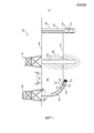
На Фиг. 1 показана схема примера буровой системы согласно аспектам настоящего изобретения.In FIG. 1 is a diagram of an example drilling system in accordance with aspects of the present invention.
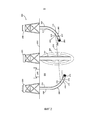
На Фиг. 2 показана схема примера буровой системы, согласно аспектам настоящего изобретения.In FIG. 2 is a diagram of an example drilling system in accordance with aspects of the present invention.
На Фиг. 3 показана схема примера способа измерения дальности, согласно аспектам настоящего изобретения.In FIG. 3 is a diagram of an example of a ranging method according to aspects of the present invention.
Хотя изобретение показано и описано в виде являющихся примерами вариантов осуществления, данные примеры не налагают ограничений на изобретение, и никаких таких ограничений не предполагают. Изобретение может претерпевать значительные модификации, замены и иметь эквиваленты по форме и функциям, понятные специалисту в данной области техники, применяющему данное изобретение. Показанные и описанные варианты осуществления изобретения являются только примерами и не исчерпывают объема изобретения.Although the invention has been shown and described as exemplary embodiments, these examples do not impose limitations on the invention and do not imply any such limitations. The invention may undergo significant modifications, replacements, and have equivalents in form and function that are understood by those skilled in the art using the invention. Shown and described embodiments of the invention are only examples and do not exhaust the scope of the invention.
ПОДРОБНОЕ ОПИСАНИЕ ИЗОБРЕТЕНИЯDETAILED DESCRIPTION OF THE INVENTION
Настоящее изобретение относится в общем к операциям бурения скважин и, конкретнее, системам и способам выполнения измерений дальности с применением привязки к третьей скважине.The present invention relates generally to well drilling operations, and more particularly, to systems and methods for making range measurements using reference to a third well.
В данном документе подробно описаны иллюстративные варианты осуществления настоящего изобретения. В интересах ясности описаны не все признаки фактической реализации. Должно быть ясно, что в разработке любого такого конкретного варианта осуществления, можно применять ряд решений, обусловленных реализацией, для достижения конкретных целей, которые могут меняться в различных вариантах реализации. Кроме того, понятно, что такая разработка может являться сложным и затратным по времени, но тем не менее рутинным мероприятием для специалиста в данной области техники, применяющего изобретение.Illustrative embodiments of the present invention are described in detail herein. In the interest of clarity, not all features of actual implementation are described. It should be clear that in developing any such specific embodiment, a number of decisions may be applied due to implementation to achieve specific goals, which may vary in different embodiments. In addition, it is clear that such a development can be complex and time-consuming, but nonetheless a routine exercise for a person skilled in the art using the invention.
Для лучшего понимания настоящего изобретения ниже приведены примеры его конкретных вариантов осуществления. Никоим образом нельзя считать данные примеры ограничивающими или определяющими объем изобретения. Варианты осуществления настоящего изобретения можно применять в горизонтальных, вертикальных, наклонно-направленных, многоствольных, с п-образными соединениями, пересекающихся, обходных (пробуренных вокруг прихваченного в скважине инструмента и обратно в скважину под ним) или иных нелинейных стволах скважин в подземных пластах любого типа. Варианты осуществления можно применять в нагнетательных скважинах, и эксплуатационных скважинах, в том числе эксплуатационных скважинах добычи минерального сырья, например сероводорода, углеводородов, или в геотермальных скважинах, а также при строительстве стволов скважин для строительства туннелей при переходе рек и других скважин для строительства туннелей при строительстве вблизи поверхности, или скважинных п-образных трубопроводов, используемых для транспортировки текучих сред, например, углеводородов. Варианты осуществления, описанные ниже, не являются ограничительными в отношении реализации.For a better understanding of the present invention, examples of its specific embodiments are given below. In no way should these examples be considered limiting or determining the scope of the invention. Embodiments of the present invention can be applied in horizontal, vertical, directional, multilateral, with U-shaped connections, intersecting, bypassing (drilled around a tool tacked in the well and back into the well below it) or other non-linear wellbores in any type of subterranean formation . Embodiments can be used in injection wells, and production wells, including production wells for the extraction of minerals, such as hydrogen sulfide, hydrocarbons, or in geothermal wells, as well as in the construction of wellbores for the construction of tunnels during river crossings and other wells for the construction of tunnels at construction near the surface, or downhole U-shaped pipelines used to transport fluids, such as hydrocarbons. The embodiments described below are not restrictive with respect to implementation.
Согласно аспектам настоящего изобретения системы и способы получения измерений дальности описаны в данном документе. Один пример способа, рассмотренный ниже, включает в себя ввод электрического тока (альтернативно именуется просто "током") в пласт из ствола первой скважины, причем ток наводит электромагнитное ("ЕМ") поле в пласте. Обычно, ток является переменным током ("АС"). Как описано ниже, ток может создаваться с помощью электрода, установленного в стволе первой скважины, или с помощью подачи электропитания на обсадную колонну, установленную в стволе первой скважины. Ток может приниматься в стволе второй скважины, например, на электроде, установленном в стволе второй скважины. Наведенное электромагнитное поле можно измерять. Электромагнитное поле можно измерять, например, из ствола первой скважины, ствола второй скважины или ствола другой скважины в пласте. Способ может также включать в себя идентификацию местоположения ствола третьей скважины в пласте по меньшей мере, частично, на основе измерения электромагнитного поля. В некоторых вариантах осуществления одна или оба из первой скважины и второй скважины могут представлять собой глушащие скважины, третья скважина может представлять собой целевую скважину. Кроме того, параметр бурения бурильной компоновки, установленной в пласте, можно менять на основе местоположения ствола третьей скважины. В некоторых вариантах осуществления, бурильная компоновка может устанавливаться в глушащей скважине, и параметром бурения может являться траектория глушащей скважины, вычисленная для пересечения целевой скважины. Предпочтительно, как описано подробно ниже, при использовании третьей скважины для измерений дальности ввод тока, прием тока и измерение может полностью перемещаться из целевой скважины и частично из глушащей скважины, увеличивая глубину измерения и достоверность измерений.According to aspects of the present invention, systems and methods for obtaining range measurements are described herein. One example of the method discussed below involves introducing an electric current (alternatively referred to simply as “current”) into the formation from the first wellbore, the current inducing an electromagnetic (“EM”) field in the formation. Typically, the current is alternating current ("AC"). As described below, current can be generated using an electrode installed in the wellbore of the first well, or by applying power to the casing installed in the wellbore of the first well. Current may be received in the wellbore of the second well, for example, on an electrode mounted in the well of the second well. The induced electromagnetic field can be measured. An electromagnetic field can be measured, for example, from a first wellbore, a second wellbore, or another wellbore in the formation. The method may also include identifying the location of the third wellbore in the formation, at least in part, based on the measurement of the electromagnetic field. In some embodiments, one or both of the first well and the second well may be jamming wells, and the third well may be the target well. In addition, the drilling parameter of the drilling assembly installed in the formation can be changed based on the location of the third wellbore. In some embodiments, the drilling assembly may be installed in a silencing well, and the drilling parameter may be the trajectory of the silencing well calculated to intersect the target well. Preferably, as described in detail below, when using a third well to measure the range, the current input, current reception and measurement can completely move from the target well and partially from the shut-off well, increasing the depth of measurement and the reliability of the measurements.
На Фиг. 1 показан пример буровой системы 100, включающей в себя дополнительный ствол скважины для измерений дальности в дополнение к одной глушащей скважине и одной целевой скважине согласно аспектам настоящего изобретения. Буровая система 100 включает в себя буровые установки 101 и 190, смонтированные на поверхности 103 и установленные над стволами скважин 102 и 106, соответственно, в подземном пласте 104. Ствол дополнительной скважины 107 может также располагаться в подземном пласте 104. В показанном варианте осуществления скважина 106 может находиться в процессе бурения и может представлять собой глушащую скважину, предназначенную для пересечения целевой скважины, как описано ниже. Буровая установка 190 может соединяться с бурильной компоновкой 150, содержащей бурильную колонну 108 и компоновку 109 низа бурильной колонны (КНБК). КНБК 109 может содержать буровое долото 110 и устройство 112 измерений во время бурения. В некоторых вариантах осуществления по меньшей мере один электрод 113 и по меньшей мере одна антенна 111 могут соединяться с КНБК 109. Как описано ниже, по меньшей мере один электрод 113 может вводить в пласт ток 115 или принимать из пласта ток 115, и по меньшей мере одна антенна 111 может измерять электромагнитное поле 120 в пласте 104, наведенное током 115. Наведенное электромагнитное поле 120 может указывать местоположение ствола 102 скважины. Как понятно специалисту в данной области техники в отношении данного изобретения, положение по меньшей мере одного электрода 113 и по меньшей мере одной антенна 111 можно переносить в различные места по бурильной компоновке. Дополнительно, в некоторых вариантах осуществления, одно или оба из электродов 113, и антенну 111 можно исключить из бурильной компоновки 150.In FIG. 1 shows an example of a
Скважина 102 может представлять собой целевую скважину, которая полностью или частично пробурена буровой установкой 101 с бурильной компоновкой аналогичной бурильной компоновке 109. Скважина 102 может являться необсаженной, частично обсаженной или полностью обсаженной. В некоторых случаях скважина 102 может являться прошедшей заканчивание скважиной, которая некоторое время эксплуатировалась, но на которой произошел катастрофический отказ, например, неконтролируемый выброс. В некоторых вариантах осуществления скважине 102 может требоваться пересечение бурильной компоновкой 109 и скважиной 106, при этом давление в скважине 102 можно уменьшить. Как описано выше, идентификация точного местоположения целевой скважины 102 может являться затруднительной. Но знание точного местоположения целевой скважины может требоваться для выбора или изменения такого параметра бурения бурильной компоновки 109, например, как траектория бурения бурильной компоновки 109 для пересечения целевой скважины 102.Well 102 may be a target well that has been wholly or partially drilled by
Согласно аспектам настоящего изобретения, может применятьcя дополнительная скважина 107, иная чем глушащая скважина 106 и целевая скважина 102, как часть измерений дальности для увеличения точности пластовых измерений. В некоторых вариантах осуществления скважина 107 может представлять собой ранее пробуренную скважину для геофизических исследований или эксплуатационную скважину в пласте 104. Аналогично, как описано ниже и показано на Фиг. 2, дополнительная скважина может также являться второй глушащей скважиной, которую бурят для пересечения целевой скважины. В показанном варианте осуществления забойный инструмент 116 на каротажном кабеле установлен в скважине 107 на каротажном кабеле 119. Как можно видеть, забойный инструмент 116 содержит по меньшей мере один электрод 118 и по меньшей мере одну антенну 117. По меньшей мере один электрод 118 может вводить переменный ток 115 в пласт 104 или принимать переменный ток 115 из пласта 104, и по меньшей мере одна антенна 117 может измерять электромагнитное поле 120, наведенное в пласте 104 током 115. Наведенное электромагнитное поле 120 может указывать местоположение скважины 102. В некоторых вариантах осуществления переменный ток может также вводиться в пласт или приниматься из пласта 104 на электроде (не показано), установленном в целевой скважине 102. При этом можно увеличить заметность целевой скважины 102. Как понятно специалисту в данной области техники, для данного изобретения конфигурация забойного инструмента 116 может меняться включением в состав по меньшей мере одного электрода 118 и по меньшей мере одной антенны 117, или исключением любого из указанного.According to aspects of the present invention, an
Забойный инструмент 116 и бурильная компоновка 150 могут поддерживать связь с блоком 105 управления на поверхности. Забойный инструмент 116, например, может поддерживать связь с поверхностью по каротажному кабелю 119, и данные, принимаемые на поверхности, могут передаваться в блок 105 управления напрямую или через беспроводную систему связи. Бурильная компоновка 150 и, в частности, КНБК 109, могут поддерживать связь с поверхностью через систему телеметрии. В некоторых вариантах осуществления блок 105 управления может содержать систему обработки информации с процессором и запоминающим устройством, соединенным с процессором. Запоминающее устройство может содержать инструкции, обеспечивающие передачу процессором управляющих сигналов на КНБК 109 и забойный инструмент 116. Например, блок 105 управления может обеспечивать ввод тока в пласт по меньшей мере одним из электродов на КНБК 109 или забойном инструменте 116, обеспечивать прием тока по меньшей мере одним из электродов на другом КНБК 109 или забойном инструменте 116, и обеспечивать измерение электромагнитного поля 120 одной из по меньшей мере одной антенны на КНБК 109 или забойном инструменте 116. Измерения могут затем приниматься на блоке 105 управления, который может обрабатывать измерения и менять параметр бурения бурильной компоновки 150 на основе обработанных измерений.The
На Фиг. 2 показан другой пример буровой системы 200, включающей в себя дополнительную скважину для измерений дальности кроме одной глушащей скважины и одной целевой скважины согласно аспектам настоящего изобретения. Буровая система 200 включает в себя буровые установки 201, 290 и 230 смонтированные на поверхности 203 и установленные над стволами скважин 202, 206 и 207, соответственно, расположенными в подземном пласте 204. В отличие от показанного на Фиг. 1, где дополнительная скважина 107 является существующей скважиной, скважина 207 может находиться в процессе бурения, аналогично скважине 206, и обе могут представлять собой глушащие скважины, предназначенные для пересечения целевой скважины/ствола скважины 202. Буровые установки 290 и 230 могут соединяться с бурильными компоновками 250 и 219, соответственно, где бурильные компоновки 250 и 219, соответственно, содержат бурильные колонны 208 и 275 и КНБК 209 и 260. КНБК 209 и 260 могут соответственно содержать буровые долота 210 и 265 и устройства 212 и 270 измерений во время бурения. В некоторых вариантах осуществления по меньшей мере один электрод 213 и 218 и по меньшей мере одна антенна 211 и 217 может соединяться с КНБК 209 и 260, соответственно. Как описано ниже, по меньшей мере один электрод одной КНБК 209 и 260 может вводить ток 215 в пласт и другой электрод может принимать ток 215. Аналогично, одна или обе из антенн 211 и 217 могут измерять электромагнитное поле 220 в пласте 204. Как описано ниже, электромагнитное поле 220 может возбуждаться в пласте 204 и вокруг скважины 202. С помощью измерения электромагнитного поля 220 буровые системы 100 и 200 могут идентифицировать местоположение целевой скважины/ствола скважины 202.In FIG. 2 shows another example of a
Положения электродов 213 и 218 на Фиг. 2, а также положения антенн 211 и 217, не накладывают ограничений. Например, в некоторых вариантах осуществления, один или оба из электродов и антенна могут исключаться из бурильных компоновок. Кроме того, число и положения стволов скважин в пластах 104 и 204 не накладывает ограничений. В некоторых вариантах осуществления дополнительные скважины могут применятьcя для исполнения способа измерения дальности. Например, вместо ввода тока в пласт или приема тока из пласта на бурильной компоновке в глушащей скважине ствол четвертой скважины с забойным инструментом аналогичным забойному инструменту 116 может применятьcя для ввода тока в пласт. В таких вариантах осуществления от бурильной компоновки может не требоваться ввод тока или прием тока, при этом от бурильной компоновки требуется только измерение электромагнитного поля в пласте. При этом можно увеличить точность измерений, поскольку на измерения не влияет интерференция от введенного или принятого на бурильной компоновке тока.The positions of the
Согласно некоторым вариантам осуществления способ получения измерений дальности также описан в данном документе. Способ может применяться в системах 100 и 200 и аналогичных системах. В некоторых вариантах осуществления способ может включать в себя ввод тока в пласт из первой скважины. Ток может вводиться с электродов, установленных в стволе скважины или в некоторых вариантах осуществления, с помощью подачи электроэнергии на обсадную колонну, установленную в стволе скважины. Способ может дополнительно содержать прием тока из пласта в стволе второй скважины. Ток может приниматься, например, через электроды, установленные в стволе скважины, или другую конструкцию возврата тока, известную в технике данного изобретения. Дополнительно, способ может включать в себя измерение наведенного электромагнитного поля с применением, например, по меньшей мере одной антенны, установленной в одной из стволов первой скважины и второй скважины.In some embodiments, a method for obtaining range measurements is also described herein. The method can be used in
Как показано на Фиг. 1, в одном варианте осуществления ток 115 может вводиться в пласт 104 по меньшей мере с одного электрода 113 в бурильной компоновке 150 и может приниматься по меньшей мере на один электрод 118 в забойном инструменте 116. В другом варианте осуществления ток 115 может вводиться в пласт 104 по меньшей мере с одного электрода 118 в забойном инструменте 116 и может приниматься по меньшей мере на один электрод 113 в бурильной компоновке 150. В любом из вариантов осуществления наведенное электромагнитное поле 120 может измеряться с помощью по меньшей мере одной антенны 111, установленной в стволе скважины 106 или по меньшей мере одной антенны 117, установленной в стволе скважины 107.As shown in FIG. 1, in one embodiment, current 115 may be introduced into
Как показано на Фиг. 2, в одном варианте осуществления ток 215 может вводиться в пласт 204 по меньшей мере с одного электрода 213 в бурильной компоновке 250, и может приниматься по меньшей мере на один электрод 218 в бурильной компоновке 219. В другом варианте осуществления ток 215 может вводиться в пласт 204 по меньшей мере с одного электрода 218 в бурильной компоновке 219, и может приниматься по меньшей мере на один электрод 213 в бурильной компоновке 250. В любом из вариантов осуществления наведенное электромагнитное поле 220 можно измерять с помощью по меньшей мере одной антенны 213, установленной в стволе скважины 206 или по меньшей мере одной антенны 217 установленной в стволе скважины 207. Дополнительно, как указано выше, ввод тока и прием можно выполнять в стволах скважин, отдельных от глушащей скважины и целевой скважины. В таких случаях, измерение может проводиться на антенне, установленной на бурильной компоновке в стволе глушащей скважины, с вводом и приемом тока в стволах двух скважин отдельных от целевой и глушащей скважин.As shown in FIG. 2, in one embodiment, current 215 may be injected into
В некоторых вариантах осуществления способ может дополнительно включать в себя идентификацию местоположения ствола третьей скважины в пласте на основе, по меньшей мере частично, измерений электромагнитного поля. Третья скважина может представлять собой целевую скважину. Как описано выше, ток, введенный в пласт, может наводить электромагнитное поле в пласте. Наведенное электромагнитное поле может идентифицировать изменения в пласте, в том числе местоположение целевой скважины. Полученные измерения электромагнитного поля могут передаваться в блок управления, где может определяться местоположение целевой скважины. Например, измерения электромагнитного поля можно сравнивать с пластовой моделью или включать в состав пластовой модели, которая создана с применением ранее собранных и обработанных данных пластовых геофизических исследований. Местоположение ствола третьей скважины можно идентифицировать, например, применяя сравнение обновленной пластовой модели.In some embodiments, the method may further include identifying a location of a third wellbore in the formation based at least in part on electromagnetic field measurements. The third well may be a target well. As described above, the current introduced into the formation may induce an electromagnetic field in the formation. The induced electromagnetic field can identify changes in the formation, including the location of the target well. The obtained measurements of the electromagnetic field can be transmitted to the control unit, where the location of the target well can be determined. For example, electromagnetic field measurements can be compared with a reservoir model or included in a reservoir model that was created using previously collected and processed data from reservoir geophysical surveys. The location of the third wellbore can be identified, for example, by comparing the updated reservoir model.
В некоторых вариантах осуществления идентификация местоположения ствола третьей скважины в пласте на основе, по меньшей мере частично, измерений электромагнитного поля может включать в себя идентификацию местоположения ствола третьей скважины по отношению по меньшей мере к одному из стволов первой скважины и второй скважины. Как показано на Фиг. 3, можно идентифицировать направление и расстояние между стволом А первой скважины, стволом В второй скважины, и стволом целевой скважины. В некоторых вариантах осуществления местоположение ствола целевой скважины можно идентифицировать с помощью измерения дальности до ствола целевой скважины от ствола первой скважины или ствола В второй скважины. Дополнительно, в некоторых вариантах осуществления местоположение ствола целевой скважины можно идентифицировать с помощью триангуляции положения ствола целевой скважины, используя его направление и расстояние до обоих, ствола А первой скважины и ствола В второй скважины. В некоторых других вариантах осуществления местоположение ствола целевой скважины можно идентифицировать с помощью определения расстояния между стволом А первой скважины и стволом В второй скважины, определяя направление от каждого из стволов скважин до целевой скважины, и применяя тригонометрические функции для идентификации положения целевой скважины. Ствол А первой скважины и ствол В второй скважины могут являться стволами глушащих скважин, скважин геофизических исследований или других скважин, описанных выше. Кроме того, ствол А первой скважины или ствол В второй скважины могут являться стволами существующих эксплуатационных скважин, или другим пластовым элементом с известным местоположением. В таких случаях, местоположение ствола целевой скважины можно идентифицировать по отношению к известному местоположению.In some embodiments, identifying the location of the third wellbore in the formation based at least in part on electromagnetic field measurements may include identifying the location of the third wellbore with respect to at least one of the first wellbore and the second wellbore. As shown in FIG. 3, the direction and distance between the wellbore A of the first well, the well B of the second well, and the well of the target well can be identified. In some embodiments, the location of the wellbore of the target well can be identified by measuring the distance to the well of the target well from the well of the first well or well of the second well. Additionally, in some embodiments, the location of the target wellbore can be identified by triangulating the position of the target wellbore using its direction and distance to both, the first wellbore A and the second wellbore B. In some other embodiments, the location of the target wellbore can be identified by determining the distance between the first wellbore A and the second wellbore B, determining the direction from each of the wellbores to the target well, and using trigonometric functions to identify the position of the target well. The wellbore A of the first well and the well B of the second well may be wells of jamming wells, geophysical exploration wells or other wells described above. In addition, the first wellbore A or the second wellbore B may be the boreholes of existing production wells, or another formation element with a known location. In such cases, the location of the target wellbore can be identified with respect to a known location.
После идентификации местоположения ствола третьей скважины способ может также включать в себя изменение параметра бурения бурильной компоновки, установленной в пласте на основе местоположения ствола третьей скважины. Как описано выше, ствол третьей скважины может представлять собой целевую скважину, с которой требуется пересечение глушащей скважины. Ствол глушащей скважины может находиться в процессе бурения и может включать в себя установленную бурильную компоновку. Примерами глушащих скважин являются скважины 106, 206 и 207, описанные выше. В некоторых вариантах осуществления, текущее положение и траекторию бурильной компоновки или КНБК можно идентифицировать, применяя измерения электромагнитного поля, пластовую модель, описанную выше или измерительное оборудование, включенное в состав бурильной компоновки/КНБК. В некоторых вариантах осуществления данные текущего положения и траектории КНБК могут передаваться в блок управления вместе с измерениями наведенного электромагнитного поля. Блок управления может корректировать параметр бурения, например, траекторию бурильной компоновки согласно указанным выше данным, при этом глушащая скважина направляется к целевой скважине. В варианте, где бурится несколько глушащих скважин, например, как показано на Фиг. 2, параметры бурения всех глушащих скважин могут меняться на основе местоположения ствола третьей скважины.After identifying the location of the third wellbore, the method may also include changing the drilling parameter of the drilling assembly installed in the formation based on the location of the third wellbore. As described above, the third wellbore may be the target well with which the completion of the shut-in well is required. A jamming wellbore may be in the process of being drilled and may include an installed drilling assembly. Examples of silencing wells are
Таким образом, настоящее изобретение успешно адаптируется для достижения целей и преимуществ, как упомянутых, так и присущих ему. Частные варианты осуществления, раскрытые выше, являются только иллюстративными, поскольку настоящее изобретение можно модифицировать и практически реализовать отличающимися, но эквивалентными способами, понятными специалисту в данной области техники, использующему идеи, изложенные в данном документе. Кроме того, не налагается ограничений по деталям конструкции или конструктивным решениям, показанным в данном документе, кроме указанных в формуле изобретения, приведенной ниже. Поэтому очевидно, что частные иллюстративные варианты осуществления, раскрытые выше, можно менять или модифицировать и все такие вариации рассматриваются относящимися к объему и сущности настоящего изобретения. Также, термины в формуле изобретения имеют свое простое общепринятое значение, если иное ясно и четко не указано заявителем. Неопределенные артикли "a" или "an", примененные в формуле изобретения, означают в данном документе один или больше одного элемента, который предваряют.Thus, the present invention is successfully adapted to achieve the goals and advantages, both mentioned and inherent in it. Particular embodiments disclosed above are only illustrative, since the present invention can be modified and practiced in different, but equivalent ways, clear to a person skilled in the art using the ideas set forth herein. In addition, there are no restrictions on the structural details or design solutions shown in this document, other than those specified in the claims below. Therefore, it is obvious that the particular illustrative embodiments disclosed above can be changed or modified and all such variations are considered to be within the scope and spirit of the present invention. Also, the terms in the claims have their simple generally accepted meaning, unless otherwise expressly and clearly indicated by the applicant. The indefinite articles “a” or “an” as used in the claims, mean in this document one or more of one element that is preceded.
Claims (73)
Applications Claiming Priority (1)
| Application Number | Priority Date | Filing Date | Title |
|---|---|---|---|
| PCT/US2012/071226 WO2014098891A1 (en) | 2012-12-21 | 2012-12-21 | Systems and methods for performing ranging measurements using third well referencing |
Publications (2)
| Publication Number | Publication Date |
|---|---|
| RU2015119252A RU2015119252A (en) | 2017-01-30 |
| RU2619952C2 true RU2619952C2 (en) | 2017-05-22 |
Family
ID=47628429
Family Applications (1)
| Application Number | Title | Priority Date | Filing Date |
|---|---|---|---|
| RU2015119252A RU2619952C2 (en) | 2012-12-21 | 2012-12-21 | System and methods of measuring distance with use of anchoring to third well |
Country Status (9)
| Country | Link |
|---|---|
| US (1) | US9625605B2 (en) |
| EP (2) | EP3115548B1 (en) |
| CN (1) | CN104919136B (en) |
| AU (1) | AU2012397234B2 (en) |
| BR (1) | BR112015011490B1 (en) |
| CA (1) | CA2892072C (en) |
| MY (1) | MY185714A (en) |
| RU (1) | RU2619952C2 (en) |
| WO (1) | WO2014098891A1 (en) |
Families Citing this family (13)
| Publication number | Priority date | Publication date | Assignee | Title |
|---|---|---|---|---|
| RU2651649C1 (en) * | 2014-12-30 | 2018-04-23 | Халлибертон Энерджи Сервисез, Инк. | Determination of location of boreholes |
| US11151762B2 (en) | 2015-11-03 | 2021-10-19 | Ubiterra Corporation | Systems and methods for shared visualization and display of drilling information |
| US20170122095A1 (en) * | 2015-11-03 | 2017-05-04 | Ubiterra Corporation | Automated geo-target and geo-hazard notifications for drilling systems |
| US10844705B2 (en) | 2016-01-20 | 2020-11-24 | Halliburton Energy Services, Inc. | Surface excited downhole ranging using relative positioning |
| DE102016002479A1 (en) * | 2016-03-03 | 2017-09-07 | Tracto-Technik Gmbh & Co. Kg | Method for drilling a hole in the ground and earth drilling device and use |
| WO2018056999A1 (en) | 2016-09-23 | 2018-03-29 | Halliburton Energy Services, Inc. | Utilizing diverse excitation sources in electromagnetic ranging |
| CA3029187C (en) | 2016-09-27 | 2020-07-21 | Halliburton Energy Services, Inc. | Calibration of electromagnetic ranging tools |
| BR112019004302B1 (en) | 2016-10-20 | 2022-11-22 | Halliburton Energy Services, Inc | METHOD TO IDENTIFY A TARGET WELL AND ELECTROMAGNETIC RANGE SYSTEM |
| WO2018143945A1 (en) | 2017-01-31 | 2018-08-09 | Halliburton Energy Services, Inc. | Optimization of ranging measurements |
| CA3055027C (en) | 2017-06-01 | 2021-10-19 | Halliburton Energy Services, Inc. | Cased-well to cased-well active magnetic ranging |
| US11434750B2 (en) | 2017-10-26 | 2022-09-06 | Halliburton Energy Services, Inc. | Determination on casing and formation properties using electromagnetic measurements |
| AU2018451194A1 (en) * | 2018-11-30 | 2021-03-18 | Halliburton Energy Services, Inc. | Multiple surface excitation method for determining a location of drilling operations to existing wells |
| CN117090558A (en) * | 2023-08-16 | 2023-11-21 | 中国石油天然气集团有限公司 | Rescue well track adjusting method and device |
Citations (6)
| Publication number | Priority date | Publication date | Assignee | Title |
|---|---|---|---|---|
| SU181570A1 (en) * | ||||
| EP0104854A2 (en) * | 1982-09-28 | 1984-04-04 | Mobil Oil Corporation | Method for the magnetization of well casing |
| EP0247672A2 (en) * | 1986-05-29 | 1987-12-02 | Shell Internationale Researchmaatschappij B.V. | Method for determining the distance between adjacent wells |
| US20090120691A1 (en) * | 2004-11-30 | 2009-05-14 | General Electric Company | Systems and methods for guiding the drilling of a horizontal well |
| RU2386810C2 (en) * | 2004-11-30 | 2010-04-20 | Дженерал Электрик Компани | Method and system for exact direction of drilling of double wells |
| US8011451B2 (en) * | 2007-10-19 | 2011-09-06 | Shell Oil Company | Ranging methods for developing wellbores in subsurface formations |
Family Cites Families (16)
| Publication number | Priority date | Publication date | Assignee | Title |
|---|---|---|---|---|
| US4372398A (en) * | 1980-11-04 | 1983-02-08 | Cornell Research Foundation, Inc. | Method of determining the location of a deep-well casing by magnetic field sensing |
| US4593770A (en) | 1984-11-06 | 1986-06-10 | Mobil Oil Corporation | Method for preventing the drilling of a new well into one of a plurality of production wells |
| US5074365A (en) * | 1990-09-14 | 1991-12-24 | Vector Magnetics, Inc. | Borehole guidance system having target wireline |
| US5485089A (en) * | 1992-11-06 | 1996-01-16 | Vector Magnetics, Inc. | Method and apparatus for measuring distance and direction by movable magnetic field source |
| US7495446B2 (en) * | 2005-08-23 | 2009-02-24 | Schlumberger Technology Corporation | Formation evaluation system and method |
| US7703548B2 (en) | 2006-08-16 | 2010-04-27 | Schlumberger Technology Corporation | Magnetic ranging while drilling parallel wells |
| US8827005B2 (en) * | 2008-04-17 | 2014-09-09 | Schlumberger Technology Corporation | Method for drilling wells in close relationship using magnetic ranging while drilling |
| US8596382B2 (en) | 2008-04-18 | 2013-12-03 | Schlumbeger Technology Corporation | Magnetic ranging while drilling using an electric dipole source and a magnetic field sensor |
| US8684107B2 (en) * | 2008-05-23 | 2014-04-01 | Schlumberger Technology Corporation | System and method for densely packing wells using magnetic ranging while drilling |
| CA2730554A1 (en) | 2008-07-24 | 2010-01-28 | Schlumberger Canada Limited | System and method for detecting casing in a formation using current |
| CA2745112A1 (en) * | 2008-12-02 | 2010-06-10 | Schlumberger Canada Limited | Electromagnetic survey using metallic well casings as electrodes |
| US8322462B2 (en) * | 2008-12-22 | 2012-12-04 | Halliburton Energy Services, Inc. | Proximity detection system for deep wells |
| GB2484842B (en) * | 2009-06-17 | 2013-07-03 | Halliburton Energy Serv Inc | Drilling collision avoidance apparatus, methods, and systems |
| EP2317069A1 (en) * | 2009-10-30 | 2011-05-04 | Welltec A/S | Magnetic ranging system for controlling a drilling process |
| CN101713287B (en) * | 2009-11-04 | 2012-10-24 | 中国石油大学(北京) | Magnetic short section used for measuring distance between adjacent wells by electromagnetic detection while drilling |
| CN101806210B (en) * | 2010-04-13 | 2014-01-01 | 中国石油大学(北京) | System using solenoid groups to achieve electromagnetic guiding distance measurement while drilling |
-
2012
- 2012-12-21 US US14/650,238 patent/US9625605B2/en active Active
- 2012-12-21 RU RU2015119252A patent/RU2619952C2/en not_active IP Right Cessation
- 2012-12-21 CA CA2892072A patent/CA2892072C/en active Active
- 2012-12-21 MY MYPI2015701576A patent/MY185714A/en unknown
- 2012-12-21 EP EP16178993.8A patent/EP3115548B1/en active Active
- 2012-12-21 WO PCT/US2012/071226 patent/WO2014098891A1/en active Application Filing
- 2012-12-21 CN CN201280077209.7A patent/CN104919136B/en not_active Expired - Fee Related
- 2012-12-21 AU AU2012397234A patent/AU2012397234B2/en not_active Ceased
- 2012-12-21 BR BR112015011490-3A patent/BR112015011490B1/en active IP Right Grant
- 2012-12-21 EP EP12819163.2A patent/EP2935779B1/en active Active
Patent Citations (6)
| Publication number | Priority date | Publication date | Assignee | Title |
|---|---|---|---|---|
| SU181570A1 (en) * | ||||
| EP0104854A2 (en) * | 1982-09-28 | 1984-04-04 | Mobil Oil Corporation | Method for the magnetization of well casing |
| EP0247672A2 (en) * | 1986-05-29 | 1987-12-02 | Shell Internationale Researchmaatschappij B.V. | Method for determining the distance between adjacent wells |
| US20090120691A1 (en) * | 2004-11-30 | 2009-05-14 | General Electric Company | Systems and methods for guiding the drilling of a horizontal well |
| RU2386810C2 (en) * | 2004-11-30 | 2010-04-20 | Дженерал Электрик Компани | Method and system for exact direction of drilling of double wells |
| US8011451B2 (en) * | 2007-10-19 | 2011-09-06 | Shell Oil Company | Ranging methods for developing wellbores in subsurface formations |
Also Published As
| Publication number | Publication date |
|---|---|
| CN104919136B (en) | 2018-07-10 |
| EP3115548B1 (en) | 2018-08-01 |
| US9625605B2 (en) | 2017-04-18 |
| EP3115548A1 (en) | 2017-01-11 |
| CA2892072C (en) | 2017-07-04 |
| CN104919136A (en) | 2015-09-16 |
| AU2012397234B2 (en) | 2016-05-19 |
| WO2014098891A1 (en) | 2014-06-26 |
| EP2935779B1 (en) | 2016-10-12 |
| US20150331139A1 (en) | 2015-11-19 |
| EP2935779A1 (en) | 2015-10-28 |
| BR112015011490B1 (en) | 2021-07-20 |
| CA2892072A1 (en) | 2014-06-26 |
| MY185714A (en) | 2021-05-31 |
| BR112015011490A2 (en) | 2017-07-11 |
| AU2012397234A1 (en) | 2015-05-21 |
| RU2015119252A (en) | 2017-01-30 |
Similar Documents
| Publication | Publication Date | Title |
|---|---|---|
| RU2619952C2 (en) | System and methods of measuring distance with use of anchoring to third well | |
| US10605072B2 (en) | Well ranging apparatus, systems, and methods | |
| US10508534B2 (en) | Planning and real time optimization of electrode transmitter excitation | |
| US10344571B2 (en) | Optimization of excitation source placement for downhole ranging and telemetry operations | |
| US10669836B2 (en) | Surface excitation ranging methods and systems employing a ground well and a supplemental grounding arrangement | |
| US11008836B2 (en) | Optimization of excitation source placement for downhole telemetry operations | |
| AU2015387499B2 (en) | Surface excitation ranging methods and systems employing a customized grounding arrangement | |
| CA3004887C (en) | Methods and systems employing a gradient sensor arrangement for ranging | |
| US11726228B2 (en) | Engineering completion and selective fracturing of lateral wellbores |
Legal Events
| Date | Code | Title | Description |
|---|---|---|---|
| MM4A | The patent is invalid due to non-payment of fees |
Effective date: 20191222 |