US10844705B2 - Surface excited downhole ranging using relative positioning - Google Patents
Surface excited downhole ranging using relative positioning Download PDFInfo
- Publication number
- US10844705B2 US10844705B2 US15/528,951 US201615528951A US10844705B2 US 10844705 B2 US10844705 B2 US 10844705B2 US 201615528951 A US201615528951 A US 201615528951A US 10844705 B2 US10844705 B2 US 10844705B2
- Authority
- US
- United States
- Prior art keywords
- measurement
- wellbore
- signal
- sensor
- relative
- Prior art date
- Legal status (The legal status is an assumption and is not a legal conclusion. Google has not performed a legal analysis and makes no representation as to the accuracy of the status listed.)
- Active
Links
- 238000005259 measurement Methods 0.000 claims abstract description 162
- 238000000034 method Methods 0.000 claims abstract description 77
- 230000005284 excitation Effects 0.000 claims description 25
- 230000015572 biosynthetic process Effects 0.000 abstract description 8
- 238000013459 approach Methods 0.000 abstract description 4
- 238000005553 drilling Methods 0.000 description 11
- 238000012545 processing Methods 0.000 description 11
- 230000008901 benefit Effects 0.000 description 9
- 238000010796 Steam-assisted gravity drainage Methods 0.000 description 7
- 238000004364 calculation method Methods 0.000 description 4
- 238000004891 communication Methods 0.000 description 4
- 238000011161 development Methods 0.000 description 3
- 230000005672 electromagnetic field Effects 0.000 description 3
- 230000008569 process Effects 0.000 description 3
- 239000004215 Carbon black (E152) Substances 0.000 description 2
- 238000012937 correction Methods 0.000 description 2
- 230000006870 function Effects 0.000 description 2
- 229930195733 hydrocarbon Natural products 0.000 description 2
- 150000002430 hydrocarbons Chemical class 0.000 description 2
- 238000009413 insulation Methods 0.000 description 2
- 238000012986 modification Methods 0.000 description 2
- 230000004048 modification Effects 0.000 description 2
- 238000010606 normalization Methods 0.000 description 2
- 238000004804 winding Methods 0.000 description 2
- 230000006978 adaptation Effects 0.000 description 1
- 238000004590 computer program Methods 0.000 description 1
- 230000003247 decreasing effect Effects 0.000 description 1
- 230000005684 electric field Effects 0.000 description 1
- 238000000605 extraction Methods 0.000 description 1
- 239000012530 fluid Substances 0.000 description 1
- 239000000295 fuel oil Substances 0.000 description 1
- 230000005484 gravity Effects 0.000 description 1
- 238000002347 injection Methods 0.000 description 1
- 239000007924 injection Substances 0.000 description 1
- 230000003993 interaction Effects 0.000 description 1
- 239000000696 magnetic material Substances 0.000 description 1
- 239000000463 material Substances 0.000 description 1
- 230000005055 memory storage Effects 0.000 description 1
- 238000012544 monitoring process Methods 0.000 description 1
- 239000003921 oil Substances 0.000 description 1
- 238000005457 optimization Methods 0.000 description 1
- 230000035515 penetration Effects 0.000 description 1
- 230000035699 permeability Effects 0.000 description 1
- 238000011084 recovery Methods 0.000 description 1
- 230000035945 sensitivity Effects 0.000 description 1
- 230000006641 stabilisation Effects 0.000 description 1
- 238000011105 stabilization Methods 0.000 description 1
- 238000012800 visualization Methods 0.000 description 1
Images


Classifications
-
- G—PHYSICS
- G01—MEASURING; TESTING
- G01V—GEOPHYSICS; GRAVITATIONAL MEASUREMENTS; DETECTING MASSES OR OBJECTS; TAGS
- G01V3/00—Electric or magnetic prospecting or detecting; Measuring magnetic field characteristics of the earth, e.g. declination, deviation
- G01V3/18—Electric or magnetic prospecting or detecting; Measuring magnetic field characteristics of the earth, e.g. declination, deviation specially adapted for well-logging
-
- E—FIXED CONSTRUCTIONS
- E21—EARTH OR ROCK DRILLING; MINING
- E21B—EARTH OR ROCK DRILLING; OBTAINING OIL, GAS, WATER, SOLUBLE OR MELTABLE MATERIALS OR A SLURRY OF MINERALS FROM WELLS
- E21B47/00—Survey of boreholes or wells
- E21B47/02—Determining slope or direction
- E21B47/022—Determining slope or direction of the borehole, e.g. using geomagnetism
- E21B47/0228—Determining slope or direction of the borehole, e.g. using geomagnetism using electromagnetic energy or detectors therefor
- E21B47/0232—Determining slope or direction of the borehole, e.g. using geomagnetism using electromagnetic energy or detectors therefor at least one of the energy sources or one of the detectors being located on or above the ground surface
-
- E—FIXED CONSTRUCTIONS
- E21—EARTH OR ROCK DRILLING; MINING
- E21B—EARTH OR ROCK DRILLING; OBTAINING OIL, GAS, WATER, SOLUBLE OR MELTABLE MATERIALS OR A SLURRY OF MINERALS FROM WELLS
- E21B7/00—Special methods or apparatus for drilling
- E21B7/04—Directional drilling
-
- G—PHYSICS
- G01—MEASURING; TESTING
- G01V—GEOPHYSICS; GRAVITATIONAL MEASUREMENTS; DETECTING MASSES OR OBJECTS; TAGS
- G01V3/00—Electric or magnetic prospecting or detecting; Measuring magnetic field characteristics of the earth, e.g. declination, deviation
- G01V3/18—Electric or magnetic prospecting or detecting; Measuring magnetic field characteristics of the earth, e.g. declination, deviation specially adapted for well-logging
- G01V3/30—Electric or magnetic prospecting or detecting; Measuring magnetic field characteristics of the earth, e.g. declination, deviation specially adapted for well-logging operating with electromagnetic waves
Definitions
- the present disclosure relates generally to downhole ranging and, more specifically, to a relative positioning system using surface excitation to determine and track the relative location of multiple wellbores.
- SAGD Steam Assisted Gravity Drainage
- FIG. 1 illustrates a relative positioning system, according to an illustrative embodiment of the present disclosure
- FIGS. 2A-2B shows an illustration of a triaxial magnetic dipole sensor configuration at each well, in relation to a linear surface source, according to certain illustrative embodiments of the present disclosure
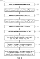
- FIG. 3 is a flow chart for a relative positioning method useful for downhole ranging applications, according to certain illustrative methods of the present disclosure
- FIG. 4 is a graph of the ranges of absolute and relative measurements as a function of distance from the source to target;
- FIG. 5 is a graph showing an actual well path vs. survey measurements with a 5% error
- FIG. 6 is a graph showing magnetic fields measured in a producer and injector well.
- FIG. 7 is a graph showing relative ranging results versus survey results (a 5% error is applied to survey), according to certain illustrative embodiments of the present disclosure.
- illustrative embodiments and methods of the present disclosure describe ranging systems that improve on the surface excitation techniques to make it more accurate and reliable. This is achieved by utilizing electromagnetic and survey measurements from a first well to calibrate a formation model, which is then used to improve the interpretation of measurements from a second well. Since the methods described herein utilize a relative approach, even though the exact position of each wellbore may not be accurately identified, their relative positions can be accurately identified. Moreover, one of the many advantages to this disclosure is that it allows the use of absolute signals rather than gradients, which improves the operational range of the surface system.
- the present disclosure may be utilized in a variety of applications, the following description will focus on applications for accurately, and reliably positioning a well being drilled (e.g., injector or monitoring well) with respect to a nearby target first well, usually the producer well, so that the injector well can be maintained approximately parallel to the producer well.
- the target well must be of a higher conductivity than the surrounding formation, which may be realized through the use of an elongated conductive body along the target well, such as, for example, casing which is already present in most wells to preserve the integrity of the well and act as a conduit for flow of produced fluids.
- the method and system of the disclosure are particularly desirable for the drilling of SAGD wells because the two wells can be drilled close to one another as is required in SAGD operations.
- FIG. 1 illustrates a relative positioning system 100 according to an illustrative embodiment of the present disclosure.
- a producer well 10 is drilled using any suitable drilling technique. Thereafter, producer well 10 is cased with casing 11 .
- An excitation source S for generating electromagnetic (“EM”) waves is positioned on surface 2 , along with a return R.
- An injector well 12 is then drilled using bottom hole assembly (“BHA”) 14 which may be, for example, a logging-while drilling (“LWD”) assembly, measurement-while drilling assembly (“MWD”) or other desired drilling assembly.
- BHA bottom hole assembly
- LWD logging-while drilling
- MWD measurement-while drilling assembly
- injector well 12 is described as being subsequently drilled, in other embodiments producer well 10 and injector well 12 may be drilled in turns.
- BHA 14 may be embodied as a wireline application (without a drilling assembly) performing logging operations, as will be understood by those same ordinarily skilled persons mentioned herein.
- the BHA/drilling assembly 14 includes one or more electromagnetic sensors 18 that sense absolute and/or gradient electromagnetic fields emitted by surface excitation source S.
- the distance and direction from surface source S to sensors 18 is determined by analyzing the measured absolute electromagnetic fields at producer and injector wells 10 , 12 , and their relative differences.
- the role of source S and sensors 18 can be changed without any difference in system operation based on EM reciprocity theorem.
- surface excitation source S can be replaced by a sensor with the same dimensions and associated antenna, and sensors 18 can be replaced by a source with the same dimensions and associated antenna, thereby reversing the roles.
- the system based on surface source S and downhole receivers 18 will be presented.
- excitation source S is located at or near surface 2 .
- source S may be any type that produces electric, magnetic or electromagnetic signals. Some examples include electrode pair, electric dipole (e.g., wire antenna, toroidal winding), magnetic dipole (e.g., coil, solenoid antenna), large loop, long curved or linear wire.
- Excitation source S can be voltage controlled, current controlled or a combination of both.
- Source S typically produces low frequency waves with frequencies in the order of, for example, 0.02-250 Hz, to achieve the depth of penetration required by SAGD applications.
- source S may be an EM pulse system which provides the advantage of multi-frequency data.
- source transmitter S and sensors 18 can be switched, it should be noted that it is more advantageous to have source S at the surface due to easier access to higher levels of power required for source operation.
- multiple sources S are required, each of which are located at a different position at surface 2 .
- Each source S can be activated sequentially or simultaneously. In the latter case, each source S can be differentiated by its frequency of operation. Due to relative measurements between the wellbores described herein, source S is required to be stable with respect to the signal level that it generates, which indicates minimal variation with time. To achieve this, the power source system may require stabilization via an internal calibration feedback loop and thermal insulation or control.
- sensors/receivers 18 are located along BHA 14 and measure all three components of the electric or magnetic fields, which could be x, y and z in the tool coordinates (i.e., triaxial). Even though use of absolute signals is sufficient for the illustrative embodiments herein, more information can be obtained by measuring phase, real or imaginary components, or gradiometric information in alternate embodiments. Here, gradiometric information may be associated with the measurements in complex domain, phase or amplitude. Due to specific operational bands of excitation source S, sensors 18 must be sensitive at this range.
- sensors 18 may be, for example, an electrode pair, electric dipole (wire antenna, toroidal winding), magnetic dipole (coil, solenoid antenna), electric loop or magnetometer.
- the magnetometers/sensors can be of flux-gate or atomic type.
- BHA 14 includes processing circuitry necessary (i.e., system control center) to achieve the relative positioning of the present disclosure in real-time.
- processing circuitry includes a communications unit to facilitate interaction between the drilling system and a remote location (such as the surface).
- a visualization unit may also be connected to communications unit to monitor the measurement data being process; for example, an operator may intervene the system operations based on this data.
- a data processing unit may convert the received data into information giving the target's position, direction and orientation in real-time. Thereafter, results may be displayed via the visualizing unit.
- the system control center of BHA 14 also includes the storage/communication circuitry necessary to perform the calculations described herein. In certain embodiments, that circuitry is communicably coupled to sensors 18 in order to process the received EM fields 20 , 22 . Additionally, the circuitry on-board BHA 14 may be communicably coupled via wired or wireless connections to the surface to thereby communicate data back uphole and/or to other assembly components (to steer a drill bit forming part of assembly 14 , for example). In an alternate embodiment, the system control center or other circuitry necessary to perform one or more aspects of the techniques described herein may be located at a remote location away from BHA 14 , such as the surface or in a different wellbore. In other embodiments, the electromagnetic field measurements may be communicated remotely to the system control center for processing. These and other variations will be readily apparent to those ordinarily skilled in the art having the benefit of this disclosure.
- the on-board circuitry includes at least one processor and a non-transitory and computer-readable storage, all interconnected via a system bus.
- Software instructions executable by the system control center for implementing the illustrative relative positioning methodologies described herein in may be stored in local storage or some other computer-readable medium. It will also be recognized that the positioning software instructions may also be loaded into the storage from a CD-ROM or other appropriate storage media via wired or wireless methods.
- a first wellbore 10 is drilled using BHA 14 .
- excitation source S emits electromagnetic waves 20 toward wellbore 10 , which are received by sensors 18 which, using processing circuitry onboard BHA 14 , generate corresponding first measurement signals.
- the first measurement signals also comprise survey measurements of the first wellbore obtained during logging operations, for example.
- BHA 14 is also used to drill a second wellbore 12 , whereby electromagnetic waves 22 are emitted by excitation source S, and received by sensors 18 to produce second measurement signals.
- the second measurement signals also include survey data previously obtained.
- processing circuitry calculates the differences between the first and second measurement signals (i.e., differential measurements). The differential measurements are then utilized to determine the relative positions of wellbores 10 and 12 .
- FIGS. 2A-2B shows an illustration of a triaxial magnetic dipole sensor configuration at each well, in relation to a linear surface source, according to certain illustrative embodiments of the present disclosure.
- only absolute signals are utilized in each well since gradient signals over such long distances would be small, thus creating a signal to noise problem.
- FIG. 1 we show two wells, an injector and producer as previously described in relation to FIG. 1 . Even though one sensor station per well is shown, multiple sensors can be used along the BHA.
- certain embodiments may include an array of triaxial sensors in either or both of the wells.
- bi-axial receivers may be used in cases where excitation source geometry and sensor orientation is well defined and well controlled.
- magnetic field distribution due to a linear source of current I in both wells can be written as:
- G is the measurement gain of the magnetometers
- r 1 radial distance of the producer from the source
- r 2 radial distance of the injector from the source
- H y1 is the y-component of the magnetic field measurement at the producer
- H y2 is the y-component of magnetic field measurement at the injector.
- the term G typically depends on the particular environment that the magnetometer is operating at such as, for example, the temperature and presence of magnetic materials in the formation.
- G By utilizing the same magnetometer in the producer and injector wells, and also through corrections on temperature variations on the sensor electronics, G can be controlled to be the same between the two wells.
- the difference in ranges i.e., differential measurement
- this differential measurement between the ranges is calculated independent of terms G and I, when r 1 and r 2 is provided by a survey measurement. It can also be observed that the error in the difference between the ranges will be in the order of the percentage error in the survey depth, which is generally lower than 5%.
- the azimuthal direction to the producer and the injector can be calculated as:
- this particular distance calculation does not depend on particular values of G or I, when r 1 and r 2 is provided by a survey measurement. It can also be observed that the error in the distance between the wells will be in the order of the percentage error in the survey depth, which is generally lower than 5%. Accordingly, electromagnetic and survey measurements from the first well are used to calibrate the formation model, which is then used to improve the interpretation of measurements from the second well. As a result, the relative position of the wells is accurately determined in a more robust and efficient manner than conventional approaches.
- FIG. 3 is a flow chart 300 for a relative positioning method useful for downhole ranging applications, according to certain illustrative methods of the present disclosure.
- the example of method 300 the surface system is deployed and activated at block 302 , and kept unchanged throughout the application. It should be emphasized that stability of the surface system (e.g., excitation source and return) is crucial for success of the proposed method, which can be achieved by different methods including, for example, measurement and feedback control and thermal insulation of the excitation source S.
- tri-axial electromagnetic measurement signals are acquired in the first well are taken, which are denoted as Hx 1 (l), Hy 1 (l) and Hz 1 (l) where l is the measured depth of the sensor during the measurement.
- EM measurements typically have units of electric field, magnetic field, voltage or current.
- the EM measurements are preferably taken on a LWD BHA in an open-hole environment; however, a wireline conveyed system, or cased-hole environment ( FIG. 1 , e.g.) can also be used.
- a bi-axial measurement can also be used in cases where the sensitivity of the third measurement is not essential.
- a survey of the first well is also taken, which is denoted as S 1 (l).
- the survey measurements can be in units of relative position and orientation relative to a reference point and coordinate system.
- EM measurements in the second well are taken and denoted as Hx 2 (l), Hy 2 (l) and Hz 2 (l), in the same way as described in block 304 .
- survey measurements in the second well are taken similar to the first well as described above, and denoted as S 2 (l).
- different relative measurements between the two wells are calculated (i.e., the term “relative measurement” is broadly used herein to denote blocks 312 , 314 or 316 ).
- the difference between the measurement signals of the wellbores is calculated using Eqs. (1)-(4) previously described, denoted as Hp 1 and Hq 2 (p and q can by the x, y or z measurements), also referred to as the differential measurement.
- the gain and current of the system is kept the same by utilizing the same sensor system in both the producer and injector wells, and controlling the surface excitation source S and downhole sensor conditions the same.
- a temperature correction may be applied to the measurements based on a surface heat run, for example.
- the differential measurement of block 312 may be normalized in certain methods.
- ratios of the differential measurement to absolute measurements of the first and second wellbores are calculated, denoted by (Hp 1 ⁇ Hq 2 )/Hr 1 and (Hp 1 ⁇ Hq 2 )/Hr 2 ).
- a ratio of the absolute measurement of the first well to the second well, or vice versa is calculated, as denoted by Hp 1 /Hq 1 , Hp 2 /Hq 2 , H 1 /Hq 2 , and Hp 2 /Hq 1 .
- an inversion procedure is conducted to determine the relative position of the wells, where an EM forward model result is calculated and compared against the real data.
- a numerical optimization is conducted to find the input parameters that match the synthetic and real results.
- the inversion is entirely based on the normalized measurement signals (differential to absolute or absolute to absolute ratios), using the survey data from both wells.
- the drilling path may be adjusted based on the calculated distance and relative direction between the wells.
- the forward model that is used in this inversion can be based on a homogeneous, 1D, 2D or 3D parameterization of the formation, with or without the borehole.
- dimensionality may be defined as the number of dimensions where the material parameters are varying.
- the forward model can be based on, for example, finite different, finite element, analytical, semi-analytical, method of moments, integral equation, or any other type of electromagnetic modeling method.
- a known or assumed formation electrical resistivity, permeability and/or permittivity distribution can be input to the model to obtain more accurate results.
- the electrical model of the formation can be updated based on a comparison between the modeled and real measurements. For example, resistivity of the model can be increased or decreased to better match the modeled and real measurements.
- one or more of the blocks 312 i.e., differential measurement
- 314 i.e., normalized measurement
- 316 i.e., absolute ratio measurement
- Blocks that are not used in the inversion can be skipped.
- the advantage of normalized measurement in block 314 compared to the differential measurement in block 312 is that any measurement errors or drifts that are common to both the first and second well measurements will be cancelled out by the ratio in block 314 .
- Block 316 will perform similarly to block 314 in principle as long as a corresponding set of ratios are used, since normalized signals in block 314 can be represented as linear combinations of terms in block 316 .
- embodiments of the present disclosure determine the relative position of two wellbores.
- the “differential measurements” measure the difference between fields at two points that are closer to each other.
- the relative signal levels are usually much smaller than the absolute signal levels that are received at individual points.
- the range of successful reception of a differential measurement is smaller compared to an absolute measurement.
- FIG. 4 is a graph of the ranges of absolute and differential measurements as a function of distance from the source to target. It shows the uncertainty of absolute measurement versus the differential measurements.
- both differential and absolute measurements can be made both in the injector and producer, but the differential measurement is more accurate due to the gain and current normalization that it provides.
- FIG. 5 shows a 5% error is introduced to both the producer and injector surveys, which is in line with what is expected in practice.
- FIG. 6 shows the Hy(l) magnetic fields that are measured at the producer and injector wells. In FIG. 6 , it is seen that the magnetic field levels are within measurable range.
- FIG. 7 shows the distance between the wells that is calculated by applying the methodology described in Equations (1)-(4). It can be seen that very accurate ranging results can be obtained without knowing precisely the current or receiver gain levels, through the use of self-normalization. It can also be seen that the survey errors did not create any significant error in the range estimation as predicted. In this example, this is partially due to cancellation of errors when the survey ranges are added in Eq. (2). Even in the worst case of constructive 5% errors in both producer and injector wells, a maximum of 10% error will be observed in range estimation which is acceptable.
- a BHA having a first sensor as described herein may be deployed along a first wellbore.
- a first measurement signal is then acquired using the first sensor.
- the BHA is then retrieved from the first wellbore, and thereafter deployed along a second wellbore, whereby a second measurement signal is acquired using the first sensor.
- a second sensor may be used to acquire the second measurement signal.
- the first and second sensors are calibrated using the same excitation source.
- the BHA may then be steered along a desired path (or to avoid a structure) based upon the relative measurements.
- a method for downhole ranging comprising acquiring first measurement signals in a first wellbore; acquiring second measurement signals in a second wellbore; calculating a relative measurement between the first and second measurement signals; and determining a position of the second wellbore relative to the first wellbore using the relative measurement.
- calculating the relative measurement comprises calculating a differential measurement between the first and the second measurement signals.
- calculating the relative measurement further comprises calculating a ratio of the differential measurement to the first or second measurement signals.
- calculating the relative measurement further comprises calculating a ratio of the first measurement signal to the second measurement signal; or the second measurement signal to the first measurement signal.
- determining the position of the second wellbore comprises performing an inversion using survey data from the first or second wellbores.
- determining the position of the second wellbore comprises performing an inversion using survey data from the first or second wellbores; and a ratio of the differential measurement to the first or second measurement signals.
- performing the inversion comprises performing the inversion using a ratio of the first measurement signal to the second measurement signal; or the second measurement signal to the first measurement signal.
- a method as defined in any of paragraphs 1-8, wherein acquiring the first and second measurement signals comprises emitting a source signal toward the first and second wellbores using a surface excitation source.
- acquiring the first and second measurement signals comprises acquiring bi-axial or triaxial measurement signals.
- acquiring the first and second measurement signals comprise at least one of acquiring absolute, phase, or real or imaginary measurements.
- a method as defined in any of paragraphs 1-15 further comprising steering the bottom hole assembly deployed along the second wellbore using the determined position of the second wellbore.
- a method as defined in any of paragraphs 1-16 further comprises avoiding the first wellbore using the determined position of the second wellbore.
- a system for downhole ranging comprising an excitation source positioned adjacent a surface location; a bottom hole assembly to be positioned along a wellbore; one or more sensors positioned along the bottom hole assembly; and processing circuitry coupled to the sensors and configured to implement a method comprising: acquiring first measurement signals in a first wellbore; acquiring second measurement signals in a second wellbore; calculating a relative measurement between the first and second measurement signals; and determining a position of the second wellbore relative to the first wellbore using the relative measurement.
- calculating the relative measurement comprises calculating a differential measurement between the first and the second measurement signals.
- calculating the relative measurement further comprises calculating a ratio of the differential measurement to the first or second measurement signals.
- calculating the relative measurement further comprises calculating a ratio of the first measurement signal to the second measurement signal; or the second measurement signal to the first measurement signal.
- excitation source is at least one of an electrode source, loop source, or dipole source.
- the methods described herein may be embodied within a system comprising processing circuitry to implement any of the methods, or a in a computer-program product comprising instructions which, when executed by at least one processor, causes the processor to perform any of the methods described herein.
Landscapes
- Life Sciences & Earth Sciences (AREA)
- Physics & Mathematics (AREA)
- Geology (AREA)
- Engineering & Computer Science (AREA)
- Mining & Mineral Resources (AREA)
- Environmental & Geological Engineering (AREA)
- General Life Sciences & Earth Sciences (AREA)
- Geophysics (AREA)
- Fluid Mechanics (AREA)
- Geochemistry & Mineralogy (AREA)
- Electromagnetism (AREA)
- Remote Sensing (AREA)
- General Physics & Mathematics (AREA)
- Measurement Of Length, Angles, Or The Like Using Electric Or Magnetic Means (AREA)
Abstract
Description
where G is the measurement gain of the magnetometers; r1 is radial distance of the producer from the source; r2 is radial distance of the injector from the source; Hy1 is the y-component of the magnetic field measurement at the producer; and Hy2 is the y-component of magnetic field measurement at the injector. The term G typically depends on the particular environment that the magnetometer is operating at such as, for example, the temperature and presence of magnetic materials in the formation. By utilizing the same magnetometer in the producer and injector wells, and also through corrections on temperature variations on the sensor electronics, G can be controlled to be the same between the two wells. By measuring the difference in magnetic fields between the wells and the average magnetic fields in both wells, the difference in ranges (i.e., differential measurement) can be calculated as:
Similar to the differential measurement calculated in Eq (2), this calculation does not depend on G or I. Finally, through geometric calculation, the distance between the wells can be found as:
Claims (17)
Applications Claiming Priority (1)
| Application Number | Priority Date | Filing Date | Title |
|---|---|---|---|
| PCT/US2016/014022 WO2017127060A1 (en) | 2016-01-20 | 2016-01-20 | Surface excited downhole ranging using relative positioning |
Publications (2)
| Publication Number | Publication Date |
|---|---|
| US20180313203A1 US20180313203A1 (en) | 2018-11-01 |
| US10844705B2 true US10844705B2 (en) | 2020-11-24 |
Family
ID=59362518
Family Applications (1)
| Application Number | Title | Priority Date | Filing Date |
|---|---|---|---|
| US15/528,951 Active US10844705B2 (en) | 2016-01-20 | 2016-01-20 | Surface excited downhole ranging using relative positioning |
Country Status (2)
| Country | Link |
|---|---|
| US (1) | US10844705B2 (en) |
| WO (1) | WO2017127060A1 (en) |
Families Citing this family (3)
| Publication number | Priority date | Publication date | Assignee | Title |
|---|---|---|---|---|
| GB2580244B (en) * | 2017-10-26 | 2022-03-09 | Halliburton Energy Services Inc | Determination on casing and formation properties using electromagnetic measurements |
| CA3083575C (en) | 2019-06-27 | 2022-01-04 | Eavor Technologies Inc. | Operational protocol for harvesting a thermally productive formation |
| CA3085901C (en) | 2020-07-06 | 2024-01-09 | Eavor Technologies Inc. | Method for configuring wellbores in a geologic formation |
Citations (29)
| Publication number | Priority date | Publication date | Assignee | Title |
|---|---|---|---|---|
| US5513710A (en) | 1994-11-07 | 1996-05-07 | Vector Magnetics, Inc. | Solenoid guide system for horizontal boreholes |
| US5515931A (en) | 1994-11-15 | 1996-05-14 | Vector Magnetics, Inc. | Single-wire guidance system for drilling boreholes |
| US5561245A (en) * | 1995-04-17 | 1996-10-01 | Western Atlas International, Inc. | Method for determining flow regime in multiphase fluid flow in a wellbore |
| US5610331A (en) * | 1995-06-01 | 1997-03-11 | Western Atlas International, Inc. | Thermal imager for fluids in a wellbore |
| US6466020B2 (en) | 2001-03-19 | 2002-10-15 | Vector Magnetics, Llc | Electromagnetic borehole surveying method |
| US6626252B1 (en) | 2002-04-03 | 2003-09-30 | Vector Magnetics Llc | Two solenoid guide system for horizontal boreholes |
| US20050211469A1 (en) | 2004-03-24 | 2005-09-29 | Vector Magnetics, Llc | Elongated coil assembly for electromagnetic borehole surveying |
| US20060066454A1 (en) | 2004-09-16 | 2006-03-30 | Vector Magnetics Llc | Earth magnetic field measurements with electronically switched current in a source loop to track a borehole |
| US7219749B2 (en) | 2004-09-28 | 2007-05-22 | Vector Magnetics Llc | Single solenoid guide system |
| US20090194333A1 (en) * | 2007-10-19 | 2009-08-06 | Macdonald Duncan | Ranging methods for developing wellbores in subsurface formations |
| US20100155139A1 (en) | 2008-12-22 | 2010-06-24 | Kuckes Arthur F | Proximity detection system for deep wells |
| US20100256913A1 (en) | 2009-04-03 | 2010-10-07 | Kuckes Arthur F | Two coil guidance system for tracking boreholes |
| US20100284250A1 (en) | 2007-12-06 | 2010-11-11 | Halliburton Energy Services, Inc. | Acoustic steering for borehole placement |
| US20120046871A1 (en) * | 2009-02-12 | 2012-02-23 | Charles Naville | Method for time picking and orientation of three-component seismic signals in wells |
| US20120139530A1 (en) * | 2010-12-07 | 2012-06-07 | Smith International, Inc. | Electromagnetic array for subterranean magnetic ranging operations |
| US20120163123A1 (en) * | 2010-12-27 | 2012-06-28 | Baker Hughes Incorporated | Stress in formations from azimuthal variation in acoustic and other properties |
| US20130144530A1 (en) * | 2010-08-31 | 2013-06-06 | Halliburton Energy Services, Inc. | Method and apparatus for downhole measurement tools |
| US20130341092A1 (en) * | 2010-11-17 | 2013-12-26 | Halliburton Energy Services, Inc. | Apparatus and method for drilling a well |
| WO2014098891A1 (en) | 2012-12-21 | 2014-06-26 | Halliburton Energy Services, Inc. | Systems and methods for performing ranging measurements using third well referencing |
| US20140374159A1 (en) * | 2013-06-25 | 2014-12-25 | Gyrodata, Incorporated | Positioning techniques in multi-well environments |
| US20150083409A1 (en) * | 2013-07-11 | 2015-03-26 | Halliburton Energy Services, Inc. | Rotationally-independent wellbore ranging |
| WO2015099785A1 (en) | 2013-12-27 | 2015-07-02 | Halliburton Energy Services, Inc. | Target well ranging method, apparatus, and system |
| US20150346381A1 (en) | 2013-03-11 | 2015-12-03 | Halliburton Energy Services, Inc. | Downhole Ranging From Multiple Boreholes |
| US20160017704A1 (en) * | 2013-03-01 | 2016-01-21 | Xact Downhole Telemetry Inc. | Range positioning tool for use within a casing or liner string |
| US20160047224A1 (en) * | 2013-12-05 | 2016-02-18 | Halliburton Energy Services Inc. | Downhole Triaxial Electromagnetic Ranging |
| US20160168977A1 (en) * | 2014-07-16 | 2016-06-16 | Halliburton Energy Services, Inc. | Optimized sagd well placement utilizing temperature and electromagnetic measurements |
| US20160216396A1 (en) * | 2013-07-31 | 2016-07-28 | Halliburton Energy Services, Inc. | Rotational Wellbore Ranging |
| US20160273345A1 (en) * | 2013-12-23 | 2016-09-22 | Halliburton Energy Services Inc. | Method and System for Magnetic Ranging and Geosteering |
| US20170275985A1 (en) * | 2015-11-06 | 2017-09-28 | Halliburton Energy Services, Inc. | Detecting a moveable device position using magnetic-type logging |
-
2016
- 2016-01-20 WO PCT/US2016/014022 patent/WO2017127060A1/en active Application Filing
- 2016-01-20 US US15/528,951 patent/US10844705B2/en active Active
Patent Citations (30)
| Publication number | Priority date | Publication date | Assignee | Title |
|---|---|---|---|---|
| US5513710A (en) | 1994-11-07 | 1996-05-07 | Vector Magnetics, Inc. | Solenoid guide system for horizontal boreholes |
| US5515931A (en) | 1994-11-15 | 1996-05-14 | Vector Magnetics, Inc. | Single-wire guidance system for drilling boreholes |
| US5561245A (en) * | 1995-04-17 | 1996-10-01 | Western Atlas International, Inc. | Method for determining flow regime in multiphase fluid flow in a wellbore |
| US5610331A (en) * | 1995-06-01 | 1997-03-11 | Western Atlas International, Inc. | Thermal imager for fluids in a wellbore |
| US6466020B2 (en) | 2001-03-19 | 2002-10-15 | Vector Magnetics, Llc | Electromagnetic borehole surveying method |
| US6626252B1 (en) | 2002-04-03 | 2003-09-30 | Vector Magnetics Llc | Two solenoid guide system for horizontal boreholes |
| US20050211469A1 (en) | 2004-03-24 | 2005-09-29 | Vector Magnetics, Llc | Elongated coil assembly for electromagnetic borehole surveying |
| US20060066454A1 (en) | 2004-09-16 | 2006-03-30 | Vector Magnetics Llc | Earth magnetic field measurements with electronically switched current in a source loop to track a borehole |
| US7219749B2 (en) | 2004-09-28 | 2007-05-22 | Vector Magnetics Llc | Single solenoid guide system |
| US20090194333A1 (en) * | 2007-10-19 | 2009-08-06 | Macdonald Duncan | Ranging methods for developing wellbores in subsurface formations |
| US20100284250A1 (en) | 2007-12-06 | 2010-11-11 | Halliburton Energy Services, Inc. | Acoustic steering for borehole placement |
| US20100155139A1 (en) | 2008-12-22 | 2010-06-24 | Kuckes Arthur F | Proximity detection system for deep wells |
| US20120046871A1 (en) * | 2009-02-12 | 2012-02-23 | Charles Naville | Method for time picking and orientation of three-component seismic signals in wells |
| US20100256913A1 (en) | 2009-04-03 | 2010-10-07 | Kuckes Arthur F | Two coil guidance system for tracking boreholes |
| US20130144530A1 (en) * | 2010-08-31 | 2013-06-06 | Halliburton Energy Services, Inc. | Method and apparatus for downhole measurement tools |
| US20130341092A1 (en) * | 2010-11-17 | 2013-12-26 | Halliburton Energy Services, Inc. | Apparatus and method for drilling a well |
| US20120139530A1 (en) * | 2010-12-07 | 2012-06-07 | Smith International, Inc. | Electromagnetic array for subterranean magnetic ranging operations |
| US20120163123A1 (en) * | 2010-12-27 | 2012-06-28 | Baker Hughes Incorporated | Stress in formations from azimuthal variation in acoustic and other properties |
| WO2014098891A1 (en) | 2012-12-21 | 2014-06-26 | Halliburton Energy Services, Inc. | Systems and methods for performing ranging measurements using third well referencing |
| US20160017704A1 (en) * | 2013-03-01 | 2016-01-21 | Xact Downhole Telemetry Inc. | Range positioning tool for use within a casing or liner string |
| US20150346381A1 (en) | 2013-03-11 | 2015-12-03 | Halliburton Energy Services, Inc. | Downhole Ranging From Multiple Boreholes |
| US20140374159A1 (en) * | 2013-06-25 | 2014-12-25 | Gyrodata, Incorporated | Positioning techniques in multi-well environments |
| US20150083409A1 (en) * | 2013-07-11 | 2015-03-26 | Halliburton Energy Services, Inc. | Rotationally-independent wellbore ranging |
| US20160216396A1 (en) * | 2013-07-31 | 2016-07-28 | Halliburton Energy Services, Inc. | Rotational Wellbore Ranging |
| US20160047224A1 (en) * | 2013-12-05 | 2016-02-18 | Halliburton Energy Services Inc. | Downhole Triaxial Electromagnetic Ranging |
| US20160273345A1 (en) * | 2013-12-23 | 2016-09-22 | Halliburton Energy Services Inc. | Method and System for Magnetic Ranging and Geosteering |
| US10294773B2 (en) * | 2013-12-23 | 2019-05-21 | Halliburton Energy Services, Inc. | Method and system for magnetic ranging and geosteering |
| WO2015099785A1 (en) | 2013-12-27 | 2015-07-02 | Halliburton Energy Services, Inc. | Target well ranging method, apparatus, and system |
| US20160168977A1 (en) * | 2014-07-16 | 2016-06-16 | Halliburton Energy Services, Inc. | Optimized sagd well placement utilizing temperature and electromagnetic measurements |
| US20170275985A1 (en) * | 2015-11-06 | 2017-09-28 | Halliburton Energy Services, Inc. | Detecting a moveable device position using magnetic-type logging |
Non-Patent Citations (4)
| Title |
|---|
| International Search Report and the Written Opinion of the International Search Authority, or the Declaration, dated Sep. 12, 2016, PCT/US2016/014022, 9 pages, ISA/KR. |
| Merriam-webster definition of range, 1 page, May 16, 2019. * |
| Merriam-webster definition of second, 1 page, May 16, 2019. * |
| Pioneer Natural Resources Uses Active Magnetic Ranging to Avoid Risk of Wellbore Collision, Halliburton, 2 pages (Year: 2008). * |
Also Published As
| Publication number | Publication date |
|---|---|
| US20180313203A1 (en) | 2018-11-01 |
| WO2017127060A1 (en) | 2017-07-27 |
Similar Documents
| Publication | Publication Date | Title |
|---|---|---|
| US10627541B2 (en) | System, method and computer-program product for in-situ calibration of a wellbore resistivity logging tool | |
| US7095232B2 (en) | Determination of borehole geometry inside cased wells with crosswell electromagnetics | |
| US10241226B2 (en) | Downhole gradiometric ranging utilizing transmitters and receivers having magnetic dipoles | |
| US10359536B2 (en) | Surface calibration of a wellbore resistivity logging tool | |
| US9714563B2 (en) | Downhole triaxial electromagnetic ranging | |
| US10294773B2 (en) | Method and system for magnetic ranging and geosteering | |
| US10001006B2 (en) | Ranging using current profiling | |
| EP2691797B1 (en) | Systems and methods for ranging while drilling | |
| US20140035586A1 (en) | Nuclear magnetic resonance logging tool having an array of antennas | |
| US11035981B2 (en) | Air-hang calibration for resistivity-logging tool | |
| CN111983703A (en) | Method, system and device for imaging fluid through interwell electromagnetic measurement | |
| US10844705B2 (en) | Surface excited downhole ranging using relative positioning | |
| US11022713B2 (en) | Dipole modeling for electric and/or magnetic fields | |
| US11320560B2 (en) | Downhole ranging using spatially continuous constraints | |
| US10227864B2 (en) | Magnetic monopole ranging system and methodology | |
| US11674378B2 (en) | Downhole ranging using 3D magnetic field and 3D gradient field measurements | |
| US10295696B2 (en) | Multi-component induction logging data processing in non-circular boreholes |
Legal Events
| Date | Code | Title | Description |
|---|---|---|---|
| AS | Assignment |
Owner name: HALLIBURTON ENERGY SERVICES, INC., TEXAS Free format text: ASSIGNMENT OF ASSIGNORS INTEREST;ASSIGNORS:DONDERICI, BURKAY;MOSS, CLINTON JAMES;SIGNING DATES FROM 20060829 TO 20160120;REEL/FRAME:042572/0715 Owner name: HALLIBURTON ENERGY SERVICES, INC., TEXAS Free format text: ASSIGNMENT OF ASSIGNORS INTEREST;ASSIGNORS:DONDERICI, BURKAY;MOSS, CLINTON JAMES;SIGNING DATES FROM 20060829 TO 20160120;REEL/FRAME:042572/0770 |
|
| STPP | Information on status: patent application and granting procedure in general |
Free format text: NON FINAL ACTION MAILED |
|
| STPP | Information on status: patent application and granting procedure in general |
Free format text: FINAL REJECTION MAILED |
|
| STCV | Information on status: appeal procedure |
Free format text: NOTICE OF APPEAL FILED |
|
| STCV | Information on status: appeal procedure |
Free format text: NOTICE OF APPEAL FILED |
|
| STPP | Information on status: patent application and granting procedure in general |
Free format text: NON FINAL ACTION MAILED |
|
| STPP | Information on status: patent application and granting procedure in general |
Free format text: FINAL REJECTION MAILED |
|
| STPP | Information on status: patent application and granting procedure in general |
Free format text: ADVISORY ACTION MAILED |
|
| STPP | Information on status: patent application and granting procedure in general |
Free format text: NON FINAL ACTION MAILED |
|
| STPP | Information on status: patent application and granting procedure in general |
Free format text: RESPONSE TO NON-FINAL OFFICE ACTION ENTERED AND FORWARDED TO EXAMINER |
|
| STPP | Information on status: patent application and granting procedure in general |
Free format text: NOTICE OF ALLOWANCE MAILED -- APPLICATION RECEIVED IN OFFICE OF PUBLICATIONS |
|
| STPP | Information on status: patent application and granting procedure in general |
Free format text: PUBLICATIONS -- ISSUE FEE PAYMENT VERIFIED |
|
| STCF | Information on status: patent grant |
Free format text: PATENTED CASE |
|
| MAFP | Maintenance fee payment |
Free format text: PAYMENT OF MAINTENANCE FEE, 4TH YEAR, LARGE ENTITY (ORIGINAL EVENT CODE: M1551); ENTITY STATUS OF PATENT OWNER: LARGE ENTITY Year of fee payment: 4 |