RU2614606C2 - Printing device and control method thereof - Google Patents
Printing device and control method thereof Download PDFInfo
- Publication number
- RU2614606C2 RU2614606C2 RU2015120286A RU2015120286A RU2614606C2 RU 2614606 C2 RU2614606 C2 RU 2614606C2 RU 2015120286 A RU2015120286 A RU 2015120286A RU 2015120286 A RU2015120286 A RU 2015120286A RU 2614606 C2 RU2614606 C2 RU 2614606C2
- Authority
- RU
- Russia
- Prior art keywords
- sheet
- printing
- roller
- previous
- unit
- Prior art date
Links
Images

Classifications
-
- B—PERFORMING OPERATIONS; TRANSPORTING
- B41—PRINTING; LINING MACHINES; TYPEWRITERS; STAMPS
- B41J—TYPEWRITERS; SELECTIVE PRINTING MECHANISMS, i.e. MECHANISMS PRINTING OTHERWISE THAN FROM A FORME; CORRECTION OF TYPOGRAPHICAL ERRORS
- B41J13/00—Devices or arrangements of selective printing mechanisms, e.g. ink-jet printers or thermal printers, specially adapted for supporting or handling copy material in short lengths, e.g. sheets
- B41J13/26—Registering devices
-
- B—PERFORMING OPERATIONS; TRANSPORTING
- B41—PRINTING; LINING MACHINES; TYPEWRITERS; STAMPS
- B41F—PRINTING MACHINES OR PRESSES
- B41F21/00—Devices for conveying sheets through printing apparatus or machines
- B41F21/10—Combinations of transfer drums and grippers
-
- B—PERFORMING OPERATIONS; TRANSPORTING
- B41—PRINTING; LINING MACHINES; TYPEWRITERS; STAMPS
- B41J—TYPEWRITERS; SELECTIVE PRINTING MECHANISMS, i.e. MECHANISMS PRINTING OTHERWISE THAN FROM A FORME; CORRECTION OF TYPOGRAPHICAL ERRORS
- B41J11/00—Devices or arrangements of selective printing mechanisms, e.g. ink-jet printers or thermal printers, for supporting or handling copy material in sheet or web form
- B41J11/0095—Detecting means for copy material, e.g. for detecting or sensing presence of copy material or its leading or trailing end
-
- B—PERFORMING OPERATIONS; TRANSPORTING
- B41—PRINTING; LINING MACHINES; TYPEWRITERS; STAMPS
- B41J—TYPEWRITERS; SELECTIVE PRINTING MECHANISMS, i.e. MECHANISMS PRINTING OTHERWISE THAN FROM A FORME; CORRECTION OF TYPOGRAPHICAL ERRORS
- B41J13/00—Devices or arrangements of selective printing mechanisms, e.g. ink-jet printers or thermal printers, specially adapted for supporting or handling copy material in short lengths, e.g. sheets
- B41J13/0009—Devices or arrangements of selective printing mechanisms, e.g. ink-jet printers or thermal printers, specially adapted for supporting or handling copy material in short lengths, e.g. sheets control of the transport of the copy material
- B41J13/0018—Devices or arrangements of selective printing mechanisms, e.g. ink-jet printers or thermal printers, specially adapted for supporting or handling copy material in short lengths, e.g. sheets control of the transport of the copy material in the sheet input section of automatic paper handling systems
-
- B—PERFORMING OPERATIONS; TRANSPORTING
- B41—PRINTING; LINING MACHINES; TYPEWRITERS; STAMPS
- B41J—TYPEWRITERS; SELECTIVE PRINTING MECHANISMS, i.e. MECHANISMS PRINTING OTHERWISE THAN FROM A FORME; CORRECTION OF TYPOGRAPHICAL ERRORS
- B41J15/00—Devices or arrangements of selective printing mechanisms, e.g. ink-jet printers or thermal printers, specially adapted for supporting or handling copy material in continuous form, e.g. webs
- B41J15/04—Supporting, feeding, or guiding devices; Mountings for web rolls or spindles
- B41J15/046—Supporting, feeding, or guiding devices; Mountings for web rolls or spindles for the guidance of continuous copy material, e.g. for preventing skewed conveyance of the continuous copy material
-
- B—PERFORMING OPERATIONS; TRANSPORTING
- B65—CONVEYING; PACKING; STORING; HANDLING THIN OR FILAMENTARY MATERIAL
- B65H—HANDLING THIN OR FILAMENTARY MATERIAL, e.g. SHEETS, WEBS, CABLES
- B65H1/00—Supports or magazines for piles from which articles are to be separated
- B65H1/04—Supports or magazines for piles from which articles are to be separated adapted to support articles substantially horizontally, e.g. for separation from top of pile
-
- B—PERFORMING OPERATIONS; TRANSPORTING
- B65—CONVEYING; PACKING; STORING; HANDLING THIN OR FILAMENTARY MATERIAL
- B65H—HANDLING THIN OR FILAMENTARY MATERIAL, e.g. SHEETS, WEBS, CABLES
- B65H3/00—Separating articles from piles
- B65H3/02—Separating articles from piles using friction forces between articles and separator
- B65H3/06—Rollers or like rotary separators
- B65H3/0684—Rollers or like rotary separators on moving support, e.g. pivoting, for bringing the roller or like rotary separator into contact with the pile
-
- B—PERFORMING OPERATIONS; TRANSPORTING
- B65—CONVEYING; PACKING; STORING; HANDLING THIN OR FILAMENTARY MATERIAL
- B65H—HANDLING THIN OR FILAMENTARY MATERIAL, e.g. SHEETS, WEBS, CABLES
- B65H5/00—Feeding articles separated from piles; Feeding articles to machines
- B65H5/06—Feeding articles separated from piles; Feeding articles to machines by rollers or balls, e.g. between rollers
- B65H5/062—Feeding articles separated from piles; Feeding articles to machines by rollers or balls, e.g. between rollers between rollers or balls
-
- B—PERFORMING OPERATIONS; TRANSPORTING
- B65—CONVEYING; PACKING; STORING; HANDLING THIN OR FILAMENTARY MATERIAL
- B65H—HANDLING THIN OR FILAMENTARY MATERIAL, e.g. SHEETS, WEBS, CABLES
- B65H5/00—Feeding articles separated from piles; Feeding articles to machines
- B65H5/06—Feeding articles separated from piles; Feeding articles to machines by rollers or balls, e.g. between rollers
- B65H5/068—Feeding articles separated from piles; Feeding articles to machines by rollers or balls, e.g. between rollers between one or more rollers or balls and stationary pressing, supporting or guiding elements
-
- B—PERFORMING OPERATIONS; TRANSPORTING
- B65—CONVEYING; PACKING; STORING; HANDLING THIN OR FILAMENTARY MATERIAL
- B65H—HANDLING THIN OR FILAMENTARY MATERIAL, e.g. SHEETS, WEBS, CABLES
- B65H5/00—Feeding articles separated from piles; Feeding articles to machines
- B65H5/24—Feeding articles in overlapping streams, i.e. by separation of articles from a pile
-
- B—PERFORMING OPERATIONS; TRANSPORTING
- B65—CONVEYING; PACKING; STORING; HANDLING THIN OR FILAMENTARY MATERIAL
- B65H—HANDLING THIN OR FILAMENTARY MATERIAL, e.g. SHEETS, WEBS, CABLES
- B65H7/00—Controlling article feeding, separating, pile-advancing, or associated apparatus, to take account of incorrect feeding, absence of articles, or presence of faulty articles
- B65H7/02—Controlling article feeding, separating, pile-advancing, or associated apparatus, to take account of incorrect feeding, absence of articles, or presence of faulty articles by feelers or detectors
- B65H7/06—Controlling article feeding, separating, pile-advancing, or associated apparatus, to take account of incorrect feeding, absence of articles, or presence of faulty articles by feelers or detectors responsive to presence of faulty articles or incorrect separation or feed
- B65H7/08—Controlling article feeding, separating, pile-advancing, or associated apparatus, to take account of incorrect feeding, absence of articles, or presence of faulty articles by feelers or detectors responsive to presence of faulty articles or incorrect separation or feed responsive to incorrect front register
-
- B—PERFORMING OPERATIONS; TRANSPORTING
- B65—CONVEYING; PACKING; STORING; HANDLING THIN OR FILAMENTARY MATERIAL
- B65H—HANDLING THIN OR FILAMENTARY MATERIAL, e.g. SHEETS, WEBS, CABLES
- B65H7/00—Controlling article feeding, separating, pile-advancing, or associated apparatus, to take account of incorrect feeding, absence of articles, or presence of faulty articles
- B65H7/20—Controlling associated apparatus
-
- B—PERFORMING OPERATIONS; TRANSPORTING
- B65—CONVEYING; PACKING; STORING; HANDLING THIN OR FILAMENTARY MATERIAL
- B65H—HANDLING THIN OR FILAMENTARY MATERIAL, e.g. SHEETS, WEBS, CABLES
- B65H9/00—Registering, e.g. orientating, articles; Devices therefor
- B65H9/002—Registering, e.g. orientating, articles; Devices therefor changing orientation of sheet by only controlling movement of the forwarding means, i.e. without the use of stop or register wall
-
- B—PERFORMING OPERATIONS; TRANSPORTING
- B65—CONVEYING; PACKING; STORING; HANDLING THIN OR FILAMENTARY MATERIAL
- B65H—HANDLING THIN OR FILAMENTARY MATERIAL, e.g. SHEETS, WEBS, CABLES
- B65H9/00—Registering, e.g. orientating, articles; Devices therefor
- B65H9/004—Deskewing sheet by abutting against a stop, i.e. producing a buckling of the sheet
- B65H9/006—Deskewing sheet by abutting against a stop, i.e. producing a buckling of the sheet the stop being formed by forwarding means in stand-by
-
- B—PERFORMING OPERATIONS; TRANSPORTING
- B65—CONVEYING; PACKING; STORING; HANDLING THIN OR FILAMENTARY MATERIAL
- B65H—HANDLING THIN OR FILAMENTARY MATERIAL, e.g. SHEETS, WEBS, CABLES
- B65H9/00—Registering, e.g. orientating, articles; Devices therefor
- B65H9/14—Retarding or controlling the forward movement of articles as they approach stops
-
- G—PHYSICS
- G06—COMPUTING; CALCULATING OR COUNTING
- G06K—GRAPHICAL DATA READING; PRESENTATION OF DATA; RECORD CARRIERS; HANDLING RECORD CARRIERS
- G06K15/00—Arrangements for producing a permanent visual presentation of the output data, e.g. computer output printers
- G06K15/02—Arrangements for producing a permanent visual presentation of the output data, e.g. computer output printers using printers
- G06K15/16—Means for paper feeding or form feeding
-
- G—PHYSICS
- G06—COMPUTING; CALCULATING OR COUNTING
- G06K—GRAPHICAL DATA READING; PRESENTATION OF DATA; RECORD CARRIERS; HANDLING RECORD CARRIERS
- G06K15/00—Arrangements for producing a permanent visual presentation of the output data, e.g. computer output printers
- G06K15/02—Arrangements for producing a permanent visual presentation of the output data, e.g. computer output printers using printers
- G06K15/18—Conditioning data for presenting it to the physical printing elements
- G06K15/1801—Input data handling means
- G06K15/1803—Receiving particular commands
-
- B—PERFORMING OPERATIONS; TRANSPORTING
- B65—CONVEYING; PACKING; STORING; HANDLING THIN OR FILAMENTARY MATERIAL
- B65H—HANDLING THIN OR FILAMENTARY MATERIAL, e.g. SHEETS, WEBS, CABLES
- B65H2301/00—Handling processes for sheets or webs
- B65H2301/30—Orientation, displacement, position of the handled material
- B65H2301/33—Modifying, selecting, changing orientation
- B65H2301/331—Skewing, correcting skew, i.e. changing slightly orientation of material
Abstract
Description
УРОВЕНЬ ТЕХНИКИ ИЗОБРЕТЕНИЯBACKGROUND OF THE INVENTION
ОБЛАСТЬ ТЕХНИКИ, К КОТОРОЙ ОТНОСИТСЯ ИЗОБРЕТЕНИЕFIELD OF THE INVENTION
Данное изобретение относится к печатающему устройству и способу управления этим печатающим устройством, а конкретнее - к печатающему устройству для транспортировки листов в область печати, обращенную к печатающей головке, путем осуществления операции коррекции перекоса передней кромки последующего листа, когда часть последующего листа перекрывает часть предыдущего листа.The present invention relates to a printing device and a method for controlling this printing device, and more particularly, to a printing device for transporting sheets to a print area facing the print head by performing an operation to correct the skew of the leading edge of a subsequent sheet when a portion of the subsequent sheet overlaps a portion of the previous sheet.
ОПИСАНИЕ ПРЕДШЕСТВУЮЩЕГО УРОВНЯ ТЕХНИКИDESCRIPTION OF THE PRIOR ART
В выложенном патенте Японии №2000-15881 описано печатающее устройство для управления таким образом, чтобы перекрывать граничную область передней кромки последующего листа с граничной областью задней кромки предыдущего листа, содержащее средство подачи для отделения и подачи множества листов одного за другим, средство печати для формирования изображения на листе, средство транспортировки для транспортировки листа к средству печати, средство обнаружения для обнаружения листа, и средство управления для управления приводом средства подачи в соответствии с сигналом средства обнаружения.Japanese Patent Laid-Open No. 2000-15881 describes a printing apparatus for controlling so as to overlap a boundary region of a leading edge of a subsequent sheet with a boundary region of a trailing edge of a previous sheet, comprising feeding means for separating and feeding a plurality of sheets one by one, printing means for forming an image on the sheet, transportation means for transporting the sheet to the printing means, detection means for detecting the sheet, and control means for controlling the drive of the feeding means in accordance with the signal of the detection means.
Однако устройство, описанное в выложенном патенте Японии № 2000-15881, может начинать подачу последующего листа только тогда, когда предельный параметр задней кромки предыдущего листа и предельный параметр передней кромки последующего листа подтверждены до начала подачи последующего листа. Это создает техническую проблему, заключающуюся в том что, до начала подачи последующего листа проходит некоторое время.However, the device described in Japanese Patent Laid-Open No. 2000-15881 can start feeding a subsequent sheet only when the limit parameter of the trailing edge of the previous sheet and the limit parameter of the leading edge of the subsequent sheet are confirmed before the start of feeding the subsequent sheet. This creates a technical problem in that it takes some time before the next sheet is fed.
КРАТКОЕ ИЗЛОЖЕНИЕ СУЩЕСТВА ИЗОБРЕТЕНИЯSUMMARY OF THE INVENTION
Данное изобретение сделано с учетом вышеупомянутой проблемы, и обеспечивает печатающее устройство, выполненное с возможностью начала подачи последующего листа даже если предельный параметр задней кромки предыдущего листа и предельный параметр передней кромки последующего листа не подтверждены, и способ управления этим печатающим устройством.The present invention is made in view of the aforementioned problem, and provides a printing apparatus configured to start feeding a subsequent sheet even if the limit parameter of the trailing edge of the previous sheet and the limit parameter of the leading edge of the subsequent sheet are not confirmed, and a method for controlling this printing device.
Чтобы решить вышеупомянутую проблему, в данном изобретении предложено печатающее устройство, содержащее: подающий валик, выполненный с возможностью подачи листа для печати, уложенного в стопку на блоке укладки в стопку; транспортирующий валик, выполненный с возможностью транспортировки листа для печати, подаваемого подающим валиком; печатающий блок, выполненный с возможностью печати на листе для печати, транспортируемом транспортирующим валиком; блок управления транспортировкой, выполненный с возможностью управления транспортировкой листов для печати таким образом, что задняя кромка предыдущего листа в качестве листа для печати, ранее поданного из блока укладки в стопку, и передняя кромка последующего листа в качестве листа для печати, впоследствии поданного из блока укладки в стопку, перекрывают друг друга; и блок коррекции перекоса, выполненный с возможностью осуществления коррекции перекоса последующего листа, когда последующий лист перекрывает предыдущий лист, с помощью блока управления транспортировкой, при этом блок коррекции перекоса заставляет переднюю кромку последующего листа упираться в транспортирующий валик в течение времени от окончания операции подачи транспортирующим валиком для печати последней строки на предыдущем листе с помощью печатающего блока до начала следующей операции транспортировки.In order to solve the aforementioned problem, the present invention provides a printing apparatus comprising: a feed roller configured to feed a print sheet stacked on a stacking unit; a conveyor roller configured to transport a sheet for printing supplied by a feed roller; a printing unit configured to print on a printing sheet transported by a conveyor roller; a transportation control unit configured to control the transportation of sheets for printing such that the trailing edge of the previous sheet as a print sheet previously supplied from the stacking unit and the leading edge of the subsequent sheet as a print sheet subsequently fed from the stacking unit in a stack, overlap each other; and a skew correction unit configured to perform skew correction of the subsequent sheet when the subsequent sheet overlaps the previous sheet with the transport control unit, wherein the skew correction unit causes the leading edge of the subsequent sheet to abut against the conveyor roller during the time from the end of the conveyor roller feed operation to print the last line on the previous sheet using the printing unit before starting the next transportation operation.
Чтобы решить вышеупомянутую проблему, в данном изобретении предложен способ управления печатающим устройством, имеющим подающий валик, выполненный с возможностью подачи листа для печати, уложенного в стопку на блоке укладки в стопку, транспортирующий валик, выполненный с возможностью транспортировки листа для печати, подаваемого подающим валиком, и печатающий блок, выполненный с возможностью печати на листе для печати, транспортируемом транспортирующим валиком, причем способ включает в себя: этап управления транспортировкой, обеспечивающий возможность управления транспортировкой листов для печати таким образом, что задняя кромка предыдущего листа в качестве листа для печати, ранее поданного из блока укладки в стопку, и передняя кромка последующего листа в качестве листа для печати, впоследствии поданного из блока укладки в стопку, перекрывают друг друга; и этап коррекции перекоса для осуществления коррекции перекоса последующего листа, когда последующий лист перекрывает предыдущий лист, на этапе управления транспортировкой, при этом на этапе коррекции перекоса переднюю кромку последующего листа заставляют упираться в транспортирующий валик в течение времени от окончания операции подачи транспортирующим валиком для печати последней строки на предыдущем листе с помощью печатающего блока до начала следующей операции транспортировки.In order to solve the aforementioned problem, the present invention provides a method for controlling a printing apparatus having a feed roller, configured to feed a print sheet stacked on a stacking unit, a conveyor roller configured to transport a sheet for printing supplied by a feed roller, and a printing unit, configured to print on the sheet for printing transported by the conveyor roller, the method including: the step of controlling transportation, providing the ability to control the transport of sheets for printing so that the trailing edge of the previous sheet as a print sheet previously fed from the stacking unit and the leading edge of the subsequent sheet as a print sheet subsequently fed from the stacking unit overlap each other friend and a skew correction step for performing skew correction of the subsequent sheet when the subsequent sheet overlaps the previous sheet in the transportation control step, while in the skew correction step, the leading edge of the subsequent sheet is forced to abut against the transport roller during the time from the end of the feeding operation by the transport roller to print the last lines on the previous sheet using the printing block before the next transportation operation.
В соответствии с данным изобретением, можно обеспечить печатающее устройство, выполненное с возможностью начинать подачу последующего листа даже если предельный параметр задней кромки предыдущего листа и предельный параметр передней кромки последующего листа не подтверждены.In accordance with this invention, it is possible to provide a printing device configured to start feeding a subsequent sheet even if the limit parameter of the trailing edge of the previous sheet and the limit parameter of the leading edge of the subsequent sheet are not confirmed.
Дополнительные признаки данного изобретения станут очевидными из нижеследующего описания возможных вариантов осуществления (приводимого со ссылками на прилагаемые чертежи).Additional features of the present invention will become apparent from the following description of possible embodiments (given with reference to the accompanying drawings).
КРАТКОЕ ОПИСАНИЕ ЧЕРТЕЖЕЙBRIEF DESCRIPTION OF THE DRAWINGS
на фиг. 1 представлен вид, поясняющий операцию непрерывной подачи с перекрытием в печатающем устройстве в соответствии с одним вариантом осуществления данного изобретения;in FIG. 1 is a view for explaining a continuous feed overlapping operation in a printing apparatus in accordance with one embodiment of the present invention;
на фиг. 2 представлен вид, поясняющий операцию непрерывной подачи с перекрытием в печатающем устройстве в соответствии с одним вариантом осуществления данного изобретения;in FIG. 2 is a view for explaining a continuous feed operation with overlapping in a printing apparatus in accordance with one embodiment of the present invention;
на фиг. 3 представлен вид, поясняющий операцию непрерывной подачи с перекрытием в печатающем устройстве в соответствии с одним вариантом осуществления данного изобретения;in FIG. 3 is a view for explaining a continuous feed overlapping operation in a printing apparatus according to one embodiment of the present invention;
на фиг. 4A и 4B представлены виды, поясняющие расположение валика захвата;in FIG. 4A and 4B are views for explaining the location of the pickup roller;
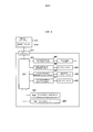
на фиг. 5 представлена блок-схема, где показано печатающее устройство в соответствии с одним вариантом осуществления;in FIG. 5 is a block diagram showing a printing apparatus in accordance with one embodiment;
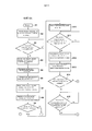
на фиг. 6А и 6В представлены блок-схемы, иллюстрирующие операцию непрерывной подачи с перекрытием в соответствии с одним вариантом осуществления;in FIG. 6A and 6B are flowcharts illustrating an overlapping continuous feed operation in accordance with one embodiment;
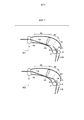
на фиг. 7 представлен вид, поясняющий операцию осуществления перекрытия предыдущего листа последующим листом;in FIG. 7 is a view explaining an operation of overlapping a previous sheet with a subsequent sheet;
на фиг. 8 представлены вид, поясняющий операцию осуществления перекрытия предыдущего листа последующим листом;in FIG. 8 is a view illustrating an operation of overlapping a previous sheet with a subsequent sheet;
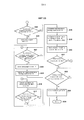
на фиг. 9 представлена блок-схема для пояснения операции коррекции перекоса последующего листа в соответствии с одним вариантом осуществления; иin FIG. 9 is a flowchart for explaining a skew correction operation of a subsequent sheet in accordance with one embodiment; and
на фиг. 10 представлена блок-схема для пояснения операции вычисления положения передней кромки последующего листа.in FIG. 10 is a flowchart for explaining an operation of calculating a position of a leading edge of a subsequent sheet.
ОПИСАНИЕ ВАРИАНТОВ ОСУЩЕСТВЛЕНИЯDESCRIPTION OF EMBODIMENTS
Ниже приводится описание вариантов осуществления данного изобретения со ссылками на прилагаемые чертежи.The following is a description of embodiments of the present invention with reference to the accompanying drawings.
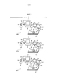
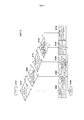
На фиг. 1-3 представлены сечения, каждое из которых схематически иллюстрирует периферийный участок пути транспортировки для пояснения операции непрерывной подачи с перекрытием в печатающем устройстве в соответствии с одним вариантом осуществления данного изобретения. Сначала, со ссылками на вид ST1 согласно фиг. 1, будет описана схематическая компоновка печатающего устройства в соответствии с вариантом осуществления.In FIG. 1-3 are sections, each of which schematically illustrates a peripheral portion of a conveyance path for explaining a continuous feed operation with overlapping in a printing apparatus in accordance with one embodiment of the present invention. First, with reference to the view ST1 of FIG. 1, a schematic arrangement of a printing apparatus according to an embodiment will be described.
Позиция 1 на виде ST1 согласно фиг. 1 обозначает листы для печати. Множество листов 1 для печати уложены в стопку на подающем лотке 11 (блок укладки стопкой). Валик 2 захвата упирается в верхний лист 1 для печати, уложенный стопкой на подающем лотке 11, чтобы захватить этот лист. Подающий валик 3 подает лист 1 для печати, захваченный валиком 2 захвата, на сторону, находящуюся дальше по ходу в направлении транспортировки листа. К подающему валику 3 смещен подающий приводной валик 4, чтобы помещать посередине лист 1 для печати вместе с подающим валиком 3, в результате чего происходит подача листа 1 для печати.
Транспортирующий валик 5 транспортирует лист 1 для печати, подаваемый подающим валиком 3 и подающим приводным валиком 4 в положение, где лист обращен к печатающей головке 7. К транспортирующему валику 5 смещен прижимной валик 6, чтобы помещать посередине лист для печати вместе с подающим валиком 3, в результате чего и происходит дальнейшая подача листа для печати.The
Печатающая головка 7 осуществляет печать на листе 1 для печати, транспортируемом транспортирующим валиком 5 и прижимным валиком 6. В этом варианте осуществления, в качестве примера можно привести печатающую головку для струйной печати, которая осуществляет печать на листе 1 для печати за счет выбрасывания чернил из печатающей головки. Бумагоопорный валик 8 поддерживает обратную поверхность листа 1 для печати в положении, где этот лист обращен к печатающей головке 7. Печатающая головка 7 установлена на каретке 10, которая перемещается в направлении, пересекающем направление транспортировки листа.The
Выводной валик 9 выводит лист для печати, на котором осуществила печать печатающая головка 7, наружу из устройства. Прямозубые зубчатые колеса 12 и 13 вращаются, находясь в контакте с отпечатанной поверхностью листа для печати, на котором осуществила печать печатающая головка 7. Прямозубое зубчатое колесо 13 на находящейся дальше по ходу стороне смещено к выводящему валику 9, а в положении, обращенном к прямозубому зубчатому колесу 12 на находящейся впереди по ходу стороне, выводящий валик 9 отсутствует. Прямозубое зубчатое колесо 12 используется для предотвращения всплывания листа 1 для печати, и оно также именуется нажимным прямозубым зубчатым колесом.The
Направляющая 15 транспортировки направляет лист 1 для печати между участком зажима при подаче, образованным подающим валиком 3 и подающим приводным валиком 4, и участком зажима при транспортировке, образованным транспортирующим валиком 5 и прижимным валиком 6. Датчик 16 обнаружения листа обнаруживает переднюю кромку и заднюю кромку листа 1 для печати. Датчик 16 обнаружения листа предусмотрен дальше по ходу от подающего валика 3 в направлении подачи листов. Рычаг 17 прижима листов обеспечивает перекрытие передней кромкой последующего листа задней кромки предыдущего листа. Рычаг 17 прижима листов отклоняется пружиной, расположенной вокруг вращающегося вала 17b, в направлении против часовой стрелки, как показано на фиг. 1.The
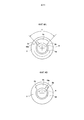
на фиг. 4A и 4B представлены виды, поясняющие расположение валика 2 захвата. Как описано выше, валик 2 захвата упирается в верхний лист для печати, уложенный в стопку на подающем лотке 11, чтобы захватить этот лист. Приводной вал 19 передает движущую силу двигателя подачи (описываемого ниже) валику 2 захвата. При захвате листа для печати, приводной вал 19 и валик 2 захвата вращаются в направлении, указанном стрелкой A на фиг. 4A и 4B. На приводном валу 19 выполнен выступ 19a. В валике 2 захвата выполнен участок 2c впадины, на который сажают выступ 19a. Как показано на фиг. 4A, когда выступ 19a упирается в первую поверхность 2a участка 2с впадины валика 2 захвата, движущая сила приводного вала 19 передается валику 2 захвата. В этом случае, когда приводной вал 19 приводится в движение, валик 2 захвата также вращается. С другой стороны, как показано на фиг. 4B, когда выступ 19a упирается во вторую поверхность 2b участка 2с впадины валика 2 захвата, движущая сила приводного вала 19 не передается валику 2 захвата. В этом случае, даже если приводной вал 19 приводится в движение, валик 2 захвата не вращается. Кроме того, когда выступ 19a выполнен между первой поверхностью 2a и второй поверхностью 2b не упирающимся в первую поверхность 2a или вторую поверхность 2b, даже если приводной вал 19 приводится в движение, валик 2 захвата не вращается.in FIG. 4A and 4B are views for explaining the location of the
На фиг. 5 представлена блок-схема, где показано печатающее устройство в соответствии с этим одним вариантом осуществления. Микропроцессорный блок (MPU) 201 управляет работой каждого блока, обработкой данных, и т.п. Как будет пояснено ниже, MPU 201 также функционирует в качестве средства управления транспортировкой, выполненного с возможностью управления транспортировкой листов для печати таким образом, что задняя кромка предыдущего листа и передняя кромка последующего листа перекрывают друг друга. Данные и программы, исполняемые MPU 201, хранятся в постоянном запоминающем устройстве (ROM) 202. Оперативное запоминающее устройство (RAM) 203 временно сохраняет данные обработки, которыми манипулирует MPU 201, и данные, принимаемые из главного компьютера 214.In FIG. 5 is a block diagram showing a printing apparatus in accordance with this one embodiment. A microprocessor unit (MPU) 201 controls the operation of each unit, data processing, and the like. As will be explained below, the
Печатающей головкой 7 управляет схема возбуждения (драйвер) 207 печатающей головки. Двигателем 204 каретки для привода каретки 10 управляет схема возбуждения 208 двигателя каретки. Двигатель 205 транспортировки приводит в движение транспортирующий валик 5 и выпускной валик 9. Двигателем 205 транспортировки управляет схема возбуждения 209 двигателя транспортировки. Двигатель 206 подачи приводит в движение валик 2 захвата и подающий валик 3. Двигателем 206 подачи управляет схема возбуждения 210 двигателя подачи.The
Для осуществления связи с печатающим устройством посредством сбора информации о печати, такой, как печатаемое изображение и качество печатаемого изображения, когда пользователь предписывает исполнение процесса печати, в главном компьютере 214 используется драйвер 2141 принтера. MPU 201 осуществляет обмен печатаемым изображением и т.п. с главным компьютером 214 через блок 313 интерфейса.To communicate with a printing device by collecting print information, such as a print image and print quality, when the user directs the printing process to be executed, the printer driver 2141 is used in the
Операция непрерывной подачи с перекрытием буден описана во временной последовательности со ссылками на показанные виды, начиная с ST1 согласно фиг. 1 и кончая ST9 согласно фиг. 3. Когда главный компьютер 214 передает данные печати через блок 213 интерфейса, MPU 201 обрабатывает данные печати, затем загружаемые в RAM 203. MPU 201 начинает операцию печати на основании загруженных данных.The continuous feed operation with overlap will be described in time sequence with reference to the views shown starting from ST1 according to FIG. 1 and ending with ST9 according to FIG. 3. When the
Теперь будет описан вид ST1 согласно фиг. 1. Схема возбуждения 210 двигателя подачи осуществляет возбуждение двигателя 206 подачи так, чтобы тот вращался с низкой скоростью. Это обуславливает вращение валика 2 захвата (первого подающего валика) со скоростью 7,6 дюйма в секунду (19,3 см/сек). Когда валик 2 захвата вращается, происходит захват верхнего листа для печати (предыдущего листа 1-A), уложенного в стопку на подающем лотке 11. Предыдущий лист 1-A, захваченный валиком 2 захвата, транспортируется подающим валиком 3 (вторым подающим валиком) в таком же направлении, в каком он транспортируется валиком 2 захвата. Двигатель 206 подачи также приводит в движение подающий валик 3. Этот вариант осуществления будет описан на примере компоновки, включающей в себя валик 2 захвата и подающий валик 3. Однако можно позаимствовать и компоновку, включающую в себя только подающий валик с целью подачи листа для печати, уложенного в стопку на блоке укладки в стопку.Now, a view of ST1 according to FIG. 1. The drive
Когда датчик 16 обнаружения листа, предусмотренный на стороне, находящейся дальше по ходу от подающего валика 3, обнаруживает переднюю кромку предыдущего листа 1-A, двигатель 206 подач переключается на приведение в действие с высокой скоростью. То есть, валик 2 захвата и подающий валик 3 вращаются со скоростью 20 дюймов в секунду (50,8 см/сек).When the
Теперь будет описан вид ST2 согласно фиг. 1. Когда подающий валик 3 непрерывно вращается, передняя кромка предыдущего листа 1-A вращает рычаг 17 прижима листов вокруг вращающегося вала 17b в направлении по часовой стрелке с противодействием отклоняющей силе пружины. Когда подающий валик 3 продолжает непрерывное вращение, передняя кромка предыдущего листа 1-A упирается в участок зажима при транспортировке, образованный транспортирующим валиком 5 и прижимным валиком 6. В этот момент, транспортирующий валик 5 останавливается. Обеспечивая дальнейшее вращение подающего валика 3 в соответствии с заранее определенным параметром после того, как передняя кромка предыдущего листа 1-A упирается в участок зажима при транспортировке, осуществляют выравнивание предыдущего листа 1-A для коррекции перекоса, когда передняя кромка предыдущего листа 1-A упирается в участок зажима при транспортировке.Now, a view of ST2 according to FIG. 1. When the
Теперь будет описан вид ST3 согласно фиг. 1. По окончании операции коррекции перекоса предыдущего листа 1-A, осуществляется возбуждение двигателя 205 транспортировки с тем, чтобы начать вращение транспортирующего валика 5. Транспортирующий валик 5 транспортирует лист со скоростью 15 дюймов в секунду (38,1 см/сек). После выравнивания предыдущего листа 1-A с положением, в котором он обращен к печатающей головке 7, осуществляется операция печати за счет выбрасывания чернил из печатающей головки 7 на основании данных печати. Отметим, что операцию выравнивания проводят, упирая переднюю кромку листа для печати в участок зажима при транспортировке, чтобы временно позиционировать лист для печати в положении, где он обращен к транспортирующему валику 5, и управляя параметром вращения транспортирующего валика 5 в соответствии с положением транспортирующего валика 5.Now, a view of ST3 according to FIG. 1. At the end of the skew correction operation of the previous sheet 1-A, the
Печатающее устройство согласно этому варианту осуществления является серийно выпускаемым печатающим устройством, в котором печатающая головка 7 установлена на каретке 10. Операцию печати на листе для печати проводят, повторяя операцию транспортировки в процессе прерывистой транспортировки листа для печати в соответствии с заранее определенным параметром с помощью транспортирующего валика 5 и операцию формирования изображения за счет выбрасывания чернил из печатающей головки 7 во время перемещения каретки 10 с установленной на ней печатающей головкой 7, когда транспортирующий валик 5 остановлен.The printing device according to this embodiment is a commercially available printing device in which the
Когда проводят выравнивание предыдущего листа 1-A, двигатель 206 подачи переключают на приведение в действие с низкой скоростью. То есть, валик 2 захвата и подающий валик 3 вращаются со скоростью 7,6 дюйма в секунду (19,3 см/сек). Когда транспортирующий валик 5 осуществляет прерывистую подачу листа для печати в соответствии с заранее определенным параметром, двигатель 206 подачи также осуществляет прерывистое приведение подающего валика 3 в движение. То есть, когда транспортирующий валик 5 вращается, подающий валик 3 тоже вращается. Когда транспортирующий валик 5 останавливается, подающий валик 3 тоже останавливается. Скорость вращения подающего валика 3 ниже, чем скорость вращения транспортирующего валика 5. Вследствие этого, лист растягивается между транспортирующим валиком 5 и подающим валиком 3. Подающий валик 3 вращается одновременно с транспортировкой листа для печати транспортирующим валиком 5.When the previous sheet 1-A is aligned, the
Поскольку осуществляется прерывистое приведение в действие двигателя 206 подачи, приводной вал 19 тоже приводится в движение. Как описано выше, скорость вращения валика 2 захвата ниже, чем скорость вращения транспортирующего валика 5. Вследствие этого, валик 2 захвата вращается одновременно с транспортировкой листа для печати транспортирующим валиком 5. То есть, валик 2 захвата вращается, опережая приводной вал 19. Конкретнее, выступ 19a приводного вала 19 отстоит от первой поверхности 2a и упирается во вторую поверхность 2b. Следовательно, второй лист для печати (последующий лист 1-B) не захватывается вскоре после того, как задняя кромка предыдущего листа 1-A проходит через валик 2 захвата. После приведения приводного вала 19 в движение в течение заранее определенного времени, выступ 19a упирается в первую поверхность 2a, а валик 2 захвата начинает вращаться.Since intermittent actuation of the
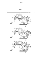
Теперь будет описан вид ST4 согласно фиг. 2. На виде ST4 показано состояние, в котором валик 2 захвата начинает вращаться и захватывает последующий лист 1-B. Ввиду такого фактора, как быстрота реакции датчика, датчику 16 обнаружения листа требуется заранее определенный интервал или большее время между листами для печати, чтобы обнаруживать кромки листов для печати. То есть, необходимо, чтобы передняя кромка последующего листа 1-B была отделена от задней кромки предыдущего листа 1-A заранее определенным расстоянием, чтобы обеспечить заранее определенный интервал времени от того момента, когда датчик 16 обнаружения листа обнаруживает заднюю кромку предыдущего листа 1-A, до того момента, когда он обнаруживает переднюю кромку последующего листа 1-B. Чтобы достичь этого, угол θ участка 2с впадины валика 2 захвата задают составляющим примерно 70°.Now, a view of ST4 according to FIG. 2. ST4 shows a state in which the
Теперь будет описан вид ST5 согласно фиг. 2. Последующий лист 1-B, отделенный валиком 2 захвата, транспортируется подающим валиком 3. В это время предыдущий лист 1-A подвергается операции формирования изображения печатающей головкой 7 на основании данных печати. Когда датчик 16 обнаружения листа обнаруживает переднюю кромку последующего листа 1-B, двигатель 206 подачи переключается на приведение в действие с высокой скоростью. То есть, валик 2 захвата и подающий валик 3 вращаются со скоростью 20 дюймов в секунду (50,8 см/сек).Now, a view of ST5 according to FIG. 2. The subsequent sheet 1-B, separated by the
Теперь будет описан вид ST6 согласно фиг. 2. Рычаг 17 прижима листов оказывает нажим вниз на заднюю кромку предыдущего листа 1-A, как показано на виде ST5 согласно фиг. 2. Можно создать состояние, в котором передняя кромка последующего листа 1-B перекрывает заднюю кромку предыдущего листа 1-A за счет перемещения последующего листа 1-B со скоростью, которая выше той, с которой предыдущий лист 1-A движется дальше по ходу перемещения за счет операции печати посредством печатающей головки 7 (вид ST6 согласно фиг. 2). Поскольку предыдущий лист 1-A подвергается операции печати на основании данных печати, происходит его прерывистая транспортировка транспортирующим валиком 5. С другой стороны, после того, как датчик 16 обнаружения листа обнаруживает переднюю кромку последующего листа 1-B, последующий лист 1-B может догнать предыдущий лист 1-A за счет непрерывного вращения подающего валика 3 со скоростью 20 дюймов в секунду (50,8 см/сек).Now, a view of ST6 according to FIG. 2. The
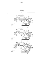
Теперь будет описан вид ST7 согласно фиг. 3. После создания состояния перекрытия, в котором передняя кромка последующего листа 1-B перекрывает заднюю кромку предыдущего листа 1-A, последующий лист 1-B транспортируется подающим валиком 3 до тех пор, пока передняя кромка последующего листа 1-B не останавливается в заранее определенном положении до достижения участка зажима при транспортировке. Положение передней кромки последующего листа 1-B вычисляется исходя из параметра вращения подающего валика 3 после того, как датчик 16 обнаружения листа обнаруживает переднюю кромку последующего листа 1-B, и на основании результата вычислений осуществляется управление упомянутым положением. В это время предыдущий лист 1-A подвергается операции формирования изображения печатающей головкой 7 на основании данных печати.Now, a view of ST7 according to FIG. 3. After creating an overlap state in which the leading edge of the subsequent sheet 1-B overlaps the trailing edge of the previous sheet 1-A, the subsequent sheet 1-B is transported by the
Теперь будет описан вид ST8 согласно фиг. 3. Когда транспортирующий валик 5 прекращает проведение операции формирования изображения (операции выбрасывания чернил) последней строки предыдущего листа 1-A, подающий валик 3 приводится в движение, упирая переднюю кромку листа 1-B для печати в участок зажима при транспортировке и тем самым проводя операцию коррекции перекоса последующего листа 1-B.Now, a view of ST8 according to FIG. 3. When the
Теперь будет описан вид ST9 согласно фиг. 3. Когда операция формирования изображения последней строки предыдущего листа 1-A заканчивается, появляется возможность осуществить выравнивание последующего листа 1-B, сохраняя состояние, в котором последующий лист 1-B перекрывает предыдущий лист 1-A, за счет вращения транспортирующего валика 5, на заранее определенную величину. Последующий лист 1-B подвергается операции печати печатающей головкой 7 на основании данных печати. Когда происходит прерывистая транспортировка последующего листа 1-B для операции печати, происходит также прерывистая транспортировка предыдущего листа 1-A, который в конце концов выводится наружу из печатающего устройства выводящим валиком 9.Now, a view of ST9 according to FIG. 3. When the image forming operation of the last row of the previous sheet 1-A ends, it becomes possible to align the subsequent sheet 1-B, maintaining the state in which the subsequent sheet 1-B overlaps the previous sheet 1-A, by rotating the
Когда осуществляется выравнивание последующего листа 1-B, двигатель 206 подачи переключается на приведение в действие с низкой скоростью. То есть, валик 2 захвата и подающий валик 3 вращаются со скоростью 7,6 дюймов в секунду (19,3 см/сек). Если данные печати имеются даже после того, как последующий лист 1-B отпечатан, процесс возвращается к состоянию, показанному на виде ST4 согласно фиг. 2, чтобы захватить третий лист для печати.When the subsequent sheet 1-B is aligned, the
На фиг. 6А и 6В представлены блок-схемы, иллюстрирующие операцию непрерывной подачи с перекрытием в соответствии с этим вариантом осуществления. На этапе S1, когда главный компьютер 214 передает данные печати через блок 213 интерфейса, начинают операцию печати. На этапе S2 начинают операцию подачи предыдущего листа 1-A. Конкретнее, приводят в действие двигатель 206 подачи с низкой скоростью. Валик 2 захвата вращается со скоростью 7,6 дюймов в секунду (19,3 см/сек). Валик 2 захвата захватывает предыдущий лист 1-A, а подающий валик 3 подает предыдущий лист 1-A к печатающей головке 7.In FIG. 6A and 6B are flowcharts illustrating an overlapping continuous feed operation in accordance with this embodiment. In step S1, when the
На этапе S3, датчик 16 обнаружения листа обнаруживает переднюю кромку предыдущего листа 1-A. Когда датчик 16 обнаружения листа обнаруживает переднюю кромку предыдущего листа 1-A, двигатель 206 подачи переключают на приведение в действие с высокой скоростью на этапе S4. То есть, валик 2 захвата и подающий валик 3 вращаются со скоростью 20 дюймов в секунду (50,8 см/сек). На этапе S5, за счет управления параметром вращения подающего валика 3 после того, как датчик 16 обнаружения листа обнаруживает переднюю кромку предыдущего листа 1-A, передняя кромка предыдущего листа 1-A упирается в участок зажима при транспортировке для осуществления операции коррекции перекоса предыдущего листа 1-A.In step S3, the
На этапе S6 проводят выравнивание предыдущего листа 1-A на основании данных печати. То есть, предыдущий лист 1-A транспортируют в положение начала печати с учетом положения транспортирующего валика 5 на основании данных печати за счет управления параметром вращения транспортирующего валика 5. На этапе S7, двигатель 206 подачи переключают на приведение в действие с низкой скоростью. На этапе S8 начинают операцию печати, когда печатающая головка 7 выбрасывает чернила на предыдущий лист 1-A. Конкретнее, операцию печати на предыдущем листе 1-A проводят, повторяя операцию транспортировки в процессе прерывистой транспортировки листа 1-A транспортирующим валиком 5 и операции формирования изображения (операции выбрасывания чернил) путем выбрасывания чернил из печатающей головки 7 за счет перемещения на каретке 10. Прерывистое приведение в действие двигателя 206 подачи с низкой скоростью осуществляют синхронно с операцией прерывистой транспортировки предыдущего листа 1-A транспортирующим валиком 5. То есть, валик 2 захвата и подающий валик 3 прерывисто вращаются со скоростью 7,6 дюймов в секунду (19,3 см/сек).In step S6, alignment of the previous sheet 1-A is performed based on the print data. That is, the previous sheet 1-A is transported to the print start position taking into account the position of the
На этапе S9 определяют, имеются ли данные печати следующей страницы. Если данных печати следующей страницы нет, процесс переходит к этапу S25. По завершении операции печати предыдущего листа 1-A на этапе S25, предыдущий лист 1-A выводят на этапе S26, тем самым заканчивая операцию печати.At step S9, it is determined whether there is print data of the next page. If there is no print data of the next page, the process proceeds to step S25. Upon completion of the printing operation of the previous sheet 1-A in step S25, the previous sheet 1-A is outputted in step S26, thereby ending the printing operation.
Если данные печати следующей страницы имеются, начинают операцию подачи последующего листа 1-B на этапе S10. Конкретнее, валик 2 захвата захватывает последующий лист 1-B, а подающий валик 3 подает последующий лист 1-B к печатающей головке 7. Валик 2 захвата вращается со скоростью 7,6 дюймов в секунду (19,3 см/сек). Как описано выше, поскольку для выступа 19a приводного вала 19 предусмотрен участок 2с большой впадины валика захвата, последующий лист 1-B подается при наличии заранее определенного интервала относительно задней кромки предыдущего листа 1-A.If the print data of the next page is available, the feeding operation of the subsequent sheet 1-B in step S10 is started. More specifically, the
На этапе S11, датчик 16 обнаружения листа обнаруживает переднюю кромку последующего листа 1-B. Когда датчик 16 обнаружения листа обнаруживает переднюю кромку последующего листа 1-B, двигатель 206 подачи переключают на приведение в действие с высокой скоростью на этапе S12. То есть, валик 2 захвата и подающий валик 3 вращаются со скоростью 20 дюймов в секунду (50,8 см/сек). На этапе S13, за счет управления параметром вращения подающего валика 3 после того, как датчик 16 обнаружения листа обнаруживает переднюю кромку последующего листа 1-B, транспортировка последующего листа 1-B происходит так, что его передняя кромка оказывается в положении, находящемся перед участком зажима при транспортировке на расстоянии, имеющем заранее определенную величину. Происходит прерывистая транспортировка предыдущего листа 1-A на основании данных печати. Непрерывное приведение в действие двигателя 206 подачи с высокой скоростью, создает состояние перекрытия, в котором передняя кромка последующего листа 1-B перекрывает заднюю кромку предыдущего листа 1-A.In step S11, the
На этапе S14 определяют, удовлетворяются ли заранее определенные условия (описываемые ниже). Если заранее определенные условия удовлетворяются, то на этапе S15 определяют, началась ли операция формирования изображения последней строки предыдущего листа 1-A. Если определяют, что операция формирования изображения последней строки началась, процесс переходит к этапу S16; в противном случае, процесс предусматривает ожидание до тех пор, пока не начинается операция формирования изображения. На этапе S16 упирают переднюю кромку последующего листа 1-B в участок зажима при транспортировке, поддерживая при этом состояние перекрытия, вследствие чего оказывается возможным проведение операции коррекции перекоса последующего листа 1-B. Отметим, что параметр вращения транспортирующего валика 5 для проведения операции подачи строки для последней строки на этапе S15 задают на 5 мкм меньшим, чем когда коррекцию перекоса проводят путем исключения состояния перекрытия (описываемого ниже) с учетом параметра перемещения предыдущего листа 1-A, обуславливаемым операцией, в ходе которой упирают последующий лист 1-B в участок зажима при транспортировке. Если на этапе S17 определяют, что операция формирования изображения последней строки предыдущего листа 1-A закончилась, то на этапе S18 проводят выравнивание последующего листа 1-B, сохраняя при этом состояние перекрытия.At step S14, it is determined whether the predetermined conditions (described below) are satisfied. If the predetermined conditions are satisfied, then it is determined in step S15 whether the image forming operation of the last row of the previous sheet 1-A has begun. If it is determined that the image forming operation of the last line has started, the process proceeds to step S16; otherwise, the process provides for waiting until the imaging operation begins. In step S16, the leading edge of the subsequent sheet 1-B is abutted against the clamping portion during transportation, while maintaining the overlap state, whereby it is possible to carry out the skew correction operation of the subsequent sheet 1-B. Note that the rotation parameter of the
Если на этапе S14 определяют, что заранее определенные условия не удовлетворяются, то состояние перекрытия исключают, чтобы провести выравнивание последующего листа 1-B. Конкретнее, если на этапе S27 определяют, что операция формирования изображения последней строки предыдущего листа 1-A закончилась, то проводят операцию вывода предыдущего листа 1-A на этапе S28. Во время этой операции, возбуждение двигателя 206 подачи не проводится, и поэтому последующий лист 1-B не движется до тех пор, пока его передняя кромка находится в положении на заранее определенном расстоянии перед участком зажима при транспортировке. Поскольку происходит вывод предыдущего листа 1-A, состояние перекрытия исключается. На этапе S29 переднюю кромку последующего листа 1-B упирают в участок зажима при транспортировке, чтобы провести операцию коррекции перекоса последующего листа 1-B. На этапе S18 проводят выравнивание последующего листа 1-B.If it is determined in step S14 that the predetermined conditions are not satisfied, then the overlap state is excluded in order to align the subsequent sheet 1-B. More specifically, if it is determined in step S27 that the image forming operation of the last row of the previous sheet 1-A is completed, then the output operation of the previous sheet 1-A in step S28 is performed. During this operation, the
На этапе S19, двигатель 206 подачи переключают на приведение в действие с низкой скоростью. На этапе S20 начинают операцию печати посредством выбрасывания чернил из печатающей головки 7 на последующий лист 1-B. Конкретнее, операцию печати последующего листа 1-B проводят, повторяя операцию транспортировки в процессе прерывистой транспортировки листа 1-B транспортирующим валиком 5 и операции формирования изображения (операции выбрасывания чернил) путем выбрасывания чернил из печатающей головки 7 за счет перемещения каретки 10. Прерывистое приведение в действие двигателя 206 подачи с низкой скоростью осуществляют синхронно с операцией прерывистой транспортировки последующего листа 1-B транспортирующим валиком 5. То есть, валик 2 захвата и подающий валик 3 прерывисто вращаются со скоростью 7,6 дюймов в секунду (19,3 см/сек).In step S19, the
На этапе S21 определяют, имеются ли данные печати следующей страницы. Если данные печати следующей страницы имеются, процесс возвращается к этапу S10. Если данных печати следующей страницы нет, то при завершении операция формирования изображения последующего листа 1-B на этапе S22, проводят операцию вывода последующего листа 1-B на этапе S23, и операция печати оканчивается на этапе S24.At step S21, it is determined whether there is print data of the next page. If the print data of the next page is available, the process returns to step S10. If there is no print data for the next page, then upon completion of the image forming operation of the subsequent sheet 1-B in step S22, the output operation of the subsequent sheet 1-B is performed in step S23, and the printing operation ends in step S24.
На фиг. 7 и 8 представлены виды, поясняющие операцию осуществления перекрытия предыдущего листа последующим листом в соответствии с этим вариантом осуществления. Теперь будет описана операция создания состояния перекрытия, в котором передняя кромка последующего листа перекрывает заднюю кромку предыдущего листа и которое пояснялось применительно к этапам S12 и S13 согласно фиг. 6A.In FIG. 7 and 8 are views illustrating an operation of overlapping a previous sheet with a subsequent sheet in accordance with this embodiment. Now will be described the operation of creating an overlap state in which the leading edge of the subsequent sheet overlaps the trailing edge of the previous sheet and which has been explained with respect to steps S12 and S13 of FIG. 6A.
На фиг. 7 и 8 представлены в увеличенном масштабе виды, каждый из которых иллюстрирует участок между участком зажима при подаче, образованным подающим валиком 3 и подающим приводным валиком 4, и участком зажима при транспортировке, образованным транспортирующим валиком 5 и прижимным валиком 6.In FIG. 7 and 8 are enlarged views, each of which illustrates a section between a feeding clamp portion formed by a
Теперь будут пояснены три состояния, наступающие в процессе транспортировки листов для печати транспортирующим валиком 5 и подающим валиком 3. Первое состояние, в котором проводят операцию, в ходе которой последующий лист преследует предыдущий лист, будет описано со ссылками на виды SV1 и SV2 согласно фиг. 7. Второе состояние, в котором проводят операцию, в ходе которой последующий лист перекрывает предыдущий лист, будет описано со ссылками на виды SV3 и SV4 согласно фиг. 8. Третье состояние, в котором определяют, проводить ли операцию коррекции перекоса последующего листа, поддерживая при этом состояние перекрытия, будет описано со ссылками на вил SV5 согласно фиг. 8.Now, three states occurring during the transportation of sheets for printing by the
На виде SV1 согласно фиг. 7 показано, что управление подающим валиком 3 осуществляют, обеспечивая транспортировку последующего листа 1-B, а датчик 16 обнаружения листа обнаруживает переднюю кромку последующего листа 1-B. Секцию от датчика 16 обнаружения листа до положения P1, в котором последующий лист 1-B можно сделать перекрывающим предыдущий лист 1-A, определяют как первую секцию A1. В первой секции A1 проводят операцию, в ходе которой передняя кромка последующего листа 1-B преследует заднюю кромку предыдущего листа 1-A. Решение о положении P1 принимают на основании компоновки механизма.In view SV1 of FIG. 7 shows that the
В первом состоянии, операцию преследования в первой секции A1 можно остановить. Если, как показано на виде SV2 согласно фиг. 7, передняя кромка последующего листа 1-B проходит заднюю кромку предыдущего листа 1-A до достижения положения P1, операцию, в ходе которой последующий лист перекрывает предыдущий лист, не проводят.In the first state, the pursuit operation in the first section A1 can be stopped. If, as shown in view SV2 of FIG. 7, the leading edge of the subsequent sheet 1-B extends the trailing edge of the previous sheet 1-A until the position P1 is reached, the operation during which the subsequent sheet overlaps the previous sheet is not performed.
На виде SV3 согласно фиг. 8, секцию от вышеописанного положения P1 до положения P2, в котором предусмотрен рычаг 17 прижима листов, определяют как вторую секцию A2. Во второй секции A2 проводят операцию, в ходе которой последующий лист 1-B перекрывает предыдущий лист 1-A.In the SV3 view of FIG. 8, a section from the above-described position P1 to the position P2 in which the
Во втором состоянии, операцию перекрытия последующим листом предыдущего листа во второй секции A2 можно остановить. Если, как показано на виде SV4 согласно фиг. 8, передняя кромка последующего листа 1-B не может догнать заднюю кромку предыдущего листа 1-A в пределах второй секции A2, то провести операцию перекрытия последующим листом предыдущего листа невозможно.In the second state, the overlapping operation of the next sheet of the previous sheet in the second section A2 can be stopped. If, as shown in the SV4 view of FIG. 8, the leading edge of the subsequent sheet 1-B cannot catch up with the leading edge of the previous sheet 1-A within the second section A2, it is not possible to perform the overlapping operation with the subsequent sheet of the previous sheet.
На виде SV5 согласно фиг. 8, секцию от вышеописанного положения P2 до положения P3 определяют как третью секцию A3. Положение P3 - это положение передней кромки последующего листа, когда последующий лист не движется на этапе S13 согласно фиг. 6A. Когда последующий лист 1-B перекрывает предыдущий лист 1-A, транспортировка последующего листа 1-B происходит таким образом, что его передняя кромка достигает положения P3. В третьей секции A3 определяют, проводить ли выравнивание последующего листа 1-B, заставляя его упираться в участок зажима при транспортировке и сохраняя при этом состояние перекрытия. То есть определяют проводить ли выравнивание последующего листа путем проведения операции коррекции перекоса с одновременным сохранением состояния перекрытия или проводить выравнивание последующего листа путем исключения состояния перекрытия и проведения операции коррекции перекоса.In the SV5 view of FIG. 8, the section from the above-described position P2 to the position P3 is determined as the third section A3. Position P3 is the position of the leading edge of the subsequent sheet when the subsequent sheet does not move in step S13 of FIG. 6A. When the subsequent sheet 1-B overlaps the previous sheet 1-A, the transportation of the subsequent sheet 1-B occurs so that its leading edge reaches position P3. In the third section A3, it is determined whether to align the subsequent sheet 1-B, forcing it to abut against the clamping portion during transportation and while maintaining the overlap state. That is, it is determined whether to align the subsequent sheet by performing a skew correction operation while maintaining the overlap state, or to align the subsequent sheet by eliminating the overlap state and performing the skew correction operation.
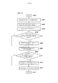
На фиг. 9 представлена блок-схема для пояснения операции коррекции перекоса последующего листа в соответствии с этим вариантом осуществления. Теперь будет подробно описана обработка, которая позволяет определить, удовлетворяются ли заранее определенные условия, и пояснена применительно к этапу S14 согласно фиг. 6A.In FIG. 9 is a flowchart for explaining a skew correction operation of a subsequent sheet in accordance with this embodiment. Now, processing that will determine whether predetermined conditions are satisfied will be described in detail, and explained with reference to step S14 of FIG. 6A.
Теперь будет описана операция определения того, проводить ли операцию коррекции перекоса, осуществляемую посредством того, что заставляют переднюю кромку последующего листа 1-B упираться в участок зажима при транспортировке и сохраняют при этом состояние перекрытия между предыдущим листом 1-A и последующим листом 1-B, или проводить операцию коррекции перекоса, осуществляемую посредством того, что исключают состояние перекрытия между предыдущим листом 1-A и последующим листом 1-B, а потом упирают переднюю кромку последующего листа 1-B в участок зажима при транспортировке.Now will be described the operation of determining whether to carry out the skew correction operation, carried out by causing the leading edge of the subsequent sheet 1-B to abut against the clamping portion during transportation, while maintaining the state of overlap between the previous sheet 1-A and the subsequent sheet 1-B or to perform the skew correction operation, which is carried out by eliminating the state of overlap between the previous sheet 1-A and the subsequent sheet 1-B, and then the leading edge of the subsequent sheet 1-B abuts against during transport to the clamp.
Работа начинается на этапе S101. На этапе S102 определяют, достигла ли передняя кромка последующего листа 1-B положения определения (положения P3 на виде SV5 согласно фиг. 8). Если передняя кромка последующего листа 1-B не достигла положения определения (ответ «НЕТ» на этапе S102), то неясно, упирается ли передняя кромка последующего листа 1-B в участок зажима при транспортировке за счет транспортировки последующего листа 1-B в соответствии с заранее определенным параметром, и поэтому принимают решение о проведении операции коррекции перекоса только для последующего листа (этап S103), вследствие чего операция определения заканчивается (этап S104). То есть, после того, как задняя кромка предыдущего листа 1-A проходит через участок зажима при транспортировке, только последующий лист 1-B упирают в участок зажима при транспортировке, чтобы провести операцию коррекции перекоса, а затем проводят выравнивание только последующего листа 1-B.Work begins at step S101. In step S102, it is determined whether the leading edge of the subsequent sheet 1-B has reached the determination position (position P3 in the view SV5 according to FIG. 8). If the leading edge of the subsequent sheet 1-B has not reached the determination position (the answer is “NO” in step S102), it is not clear whether the leading edge of the subsequent sheet 1-B abuts against the clamping portion during transportation by transporting the subsequent sheet 1-B in accordance with a predetermined parameter, and therefore, a decision is made to perform the skew correction operation only for the subsequent sheet (step S103), whereby the determination operation ends (step S104). That is, after the trailing edge of the previous sheet 1-A passes through the clamping portion during transportation, only the subsequent sheet 1-B is abutted in the clamping portion during transportation to perform the skew correction operation, and then only the subsequent sheet 1-B is aligned. .
С другой стороны, если определяют, что последующий лист 1-B достиг положения определения P3 (ответ «ДА» на этапе S102), то определяют, прошла ли задняя кромка предыдущего листа 1-A через участок зажима при транспортировке (этап S105). Если определяют, что задняя кромка предыдущего листа 1-A прошла через участок зажима при транспортировке (ответ «ДА» на этапе S105), то последующий лист не перекрывает предыдущий лист, и поэтому принимают решение о проведении операции коррекции перекоса только последующего листа (этап S106). То есть, только последующий лист 1-B упирают в участок зажима при транспортировке, чтобы провести операцию коррекции перекоса, а затем проводят выравнивание только последующего листа 1-B.On the other hand, if it is determined that the subsequent sheet 1-B has reached the determination position P3 (answer “YES” in step S102), then it is determined whether the trailing edge of the previous sheet 1-A has passed through the clamping portion during transportation (step S105). If it is determined that the trailing edge of the previous sheet 1-A passed through the clamping portion during transportation (the answer is “YES” in step S105), then the subsequent sheet does not overlap the previous sheet, and therefore, it is decided to perform the skew correction operation of only the subsequent sheet (step S106 ) That is, only the subsequent sheet 1-B is abutted in the clamping portion during transportation to perform a skew correction operation, and then only the subsequent sheet 1-B is aligned.
С другой стороны, если определяют, что задняя кромка предыдущего листа 1-A не прошла через участок зажима при транспортировке (ответ «НЕТ» на этапе S105), то определяют, меньше ли величина перекрытия задней кромки предыдущего листа 1-A и передней кромки последующего листа 1-B, чем пороговое значение (этап S107). Положение задней кромки предыдущего листа 1-A обновляют при проведении операции печати предыдущего листа 1-A. Положение передней кромки последующего листа 1-B оказывается вышеописанным положением определения. То есть, величина перекрытия при проведении операции печати предыдущего листа 1-A уменьшается. Если определяют, что величина перекрытия меньше, чем пороговое значение (ответ «ДА» на этапе S107), то состояние перекрытия исключают, и принимают решение о проведении операции коррекции перекоса только последующего листа (этап S108). То есть, после того, как операция формирования изображения предыдущего листа 1-A заканчивается, последующий лист 1-B не транспортируют вместе с предыдущим листом 1-A. Конкретнее, двигатель 205 транспортировки приводит в движение транспортирующий валик 5 для транспортировки предыдущего листа 1-A. Однако подающий валик 3 в движение не приводится. Поэтому состояние перекрытия исключается. Помимо этого, только последующий лист 1-B упирают в участок зажима при транспортировке, чтобы провести операцию коррекции перекоса, а затем проводят выравнивание только последующего листа 1-B.On the other hand, if it is determined that the trailing edge of the previous sheet 1-A has not passed through the clamping portion during transportation (“NO” in step S105), then it is determined whether the overlap of the trailing edge of the previous sheet 1-A and the leading edge of the subsequent one is less than sheet 1-B than the threshold value (step S107). The position of the trailing edge of the previous sheet 1-A is updated during the printing operation of the previous sheet 1-A. The position of the leading edge of the subsequent sheet 1-B is the above-described determination position. That is, the amount of overlap during the printing operation of the previous sheet 1-A decreases. If it is determined that the overlap value is less than the threshold value (answer “YES” in step S107), the overlap state is excluded, and a decision is made to perform the skew correction operation of only the subsequent sheet (step S108). That is, after the image forming operation of the previous sheet 1-A ends, the subsequent sheet 1-B is not transported together with the previous sheet 1-A. More specifically, the
Если определяют, что величина перекрытия равна пороговому значению или больше него (ответ «НЕТ» на этапе S107), то определяют, достиг ли последующий лист 1-B нажимного прямозубого зубчатого колеса 12, когда осуществляют выравнивание последующего листа 1-B (этап S109). Если определяют, что последующий лист 1-B не достиг нажимного прямозубого зубчатого колеса 12 (ответ «НЕТ» на этапе S109), то состояние перекрытия исключают, и принимают решение о проведении операции коррекции перекоса только для последующего листа (этап S110). То есть, после того, как операции формирования изображения предыдущего листа 1-A заканчивается, последующий лист 1-B не транспортируют вместе с предыдущим листом 1-A. Конкретнее, двигатель 205 транспортировки приводит транспортирующий валик 5 в движение для транспортировки предыдущего листа 1-A. Однако подающий валик 3 в движение не приводится. Поэтому состояние перекрытия исключается. Помимо этого, только последующий лист 1-B упирают в участок зажима при транспортировке, чтобы провести операцию коррекции перекоса, а затем проводят выравнивание только последующего листа 1-B.If it is determined that the overlap value is equal to or greater than the threshold value (the answer is “NO” in step S107), then it is determined whether the subsequent spindle gear sheet 1-B has reached the
Если определяют, что последующий лист 1-B достиг нажимного прямозубого зубчатого колеса 12 (ответ «ДА» на этапе S109), то операцию коррекции перекоса последующего листа 1-B проводят, сохраняя при этом состояние перекрытия (этап S112), а затем проводят выравнивание последующего листа 1-B. То есть, во время операции формирования изображения предыдущего листа 1-A (в течение времени от момента окончания операции подачи последней строки, до следующей операции транспортировки), переднюю кромку последующего листа 1-B упирают в участок зажима при транспортировке, а последующий лист 1-B перекрывает предыдущий лист 1-A. Конкретнее, транспортирующий валик 5 и подающий валик 3 вращаются за счет приведения их в движение двигателем 206 подачи вместе с двигателем 205 транспортировки. После операции коррекции перекоса проводят выравнивание последующего листа 1-B, а последующий лист 1-B при этом перекрывает предыдущий лист 1-A.If it is determined that the subsequent sheet 1-B has reached the spur gear 12 (the answer is “YES” in step S109), then the skew correction operation of the subsequent sheet 1-B is carried out while maintaining the overlap state (step S112), and then align subsequent sheet 1-B. That is, during the image forming operation of the previous sheet 1-A (during the time from the end of the last line feed operation to the next transportation operation), the leading edge of the subsequent sheet 1-B is abutted in the clamping portion during transportation, and the subsequent sheet 1- B overlaps the previous sheet 1-A. More specifically, the
Как описано выше, проводят операцию определения того, сохранить или исключить состояние перекрытия между предыдущим листом 1-A и последующим листом 1-B.As described above, an operation is performed to determine whether to maintain or eliminate the overlap state between the previous sheet 1-A and the subsequent sheet 1-B.
На фиг. 10 представлена блок-схема для пояснения операции вычисления положения передней кромки последующего листа после выравнивания последующего листа в соответствии с этим вариантом осуществления.In FIG. 10 is a flowchart for explaining an operation of calculating a leading edge position of a subsequent sheet after aligning a subsequent sheet in accordance with this embodiment.
Процесс начинается на этапе S201. На этапе S202 загружают область печати с размером листов. Поскольку крайнее верхнее положение печати, то есть, граница на верхнем конце задана, границу на верхнем конце области печати задают как положение передней кромки (этап S203). Отметим, что положение передней кромки определяется расстоянием от участка зажима при транспортировке.The process starts at step S201. In step S202, a print area with a sheet size is loaded. Since the topmost print position, that is, the border at the upper end is set, the border at the upper end of the print area is set as the position of the leading edge (step S203). Note that the position of the leading edge is determined by the distance from the clamp portion during transportation.
Загружают первые данные печати (этап S204). С помощью этой обработки, задают положение первых данных печати от передней кромки листа (обнаружение области отсутствия печати) и тем самым определяют больше ли расстояние между передней кромкой листа и первыми данными печати, чем ранее заданное положение передней кромки (этап S205). Если расстояние между передней кромкой листа и первыми данными печати больше, чем ранее заданное положение передней кромки (ответ «ДА» на этапе S205), то положение передней кромки обновляют расстоянием между кромкой листа и первыми данными печати (этап S206). Если расстояние между передней кромкой листа и первыми данными печати равно ранее заданному положению передней кромки или меньше него (ответ «НЕТ» на этапе S205), то процесс переходит к этапу S207.Downloading the first print data (step S204). With this processing, the position of the first print data from the leading edge of the sheet (detecting the lack of print area) is set and thereby determining whether the distance between the leading edge of the sheet and the first print data is greater than the previously set leading edge position (step S205). If the distance between the leading edge of the sheet and the first print data is greater than the previously set leading edge position (answer “YES” in step S205), then the position of the leading edge is updated with the distance between the edge of the sheet and the first printing data (step S206). If the distance between the leading edge of the sheet and the first print data is equal to or less than the predetermined position of the leading edge (answer “NO” in step S205), the process proceeds to step S207.
Далее, генерируют команду первого движения каретки (этап S207). Определяют, больше ли величина транспортировки листа для первого движения каретки, чем ранее заданное положение передней кромки (этап S208). Если величина транспортировки листа для первого движения каретки больше, чем ранее заданное положение передней кромки (ответ «ДА» на этапе S208), то положение передней кромки обновляют посредством величины транспортировки листа для первого движения каретки (этап S209). Если величина транспортировки листа для первого движения каретки равна ранее заданному положению передней кромки, или меньше него (ответ «НЕТ» на этапе S208), то положение передней кромки не обновляют. Таким образом, положение передней кромки последующего листа 1-B подтверждается (этап S210), а процесс заканчивается (этап S211). На основании подтвержденного положения передней кромки, появляется возможность определить (этап S109 согласно фиг. 9), достиг ли последующий лист 1-B нажимного прямозубого зубчатого колеса 12 при осуществлении выравнивания последующего листа B.Next, a first carriage movement command is generated (step S207). It is determined whether the sheet transport amount for the first carriage movement is greater than the previously set leading edge position (step S208). If the sheet transport amount for the first carriage movement is greater than the previously set leading edge position (answer “YES” in step S208), then the leading edge position is updated by the sheet transport amount for the first carriage movement (step S209). If the sheet transport amount for the first carriage movement is equal to or less than a predetermined leading edge position (answer “NO” in step S208), then the leading edge position is not updated. Thus, the position of the leading edge of the subsequent sheet 1-B is confirmed (step S210), and the process ends (step S211). Based on the confirmed position of the leading edge, it becomes possible to determine (step S109 according to FIG. 9) whether the subsequent sheet 1-B has reached the
Как описано выше, в соответствии с указанным вариантом осуществления, за счет определения того, транспортировать ли последующий лист в положение, в котором он обращен к печатающая головка 7, с одновременным сохранением состояния перекрытия, когда передняя кромка последующего листа 1-B перекрывает заднюю кромку предыдущего листа 1-A, появляется возможность начинать подачу последующего листа даже в случае, если предельная величина задней кромки предыдущего листа и предельная величина передней кромки последующего листа не подтверждены.As described above, in accordance with the indicated embodiment, by determining whether to transport the subsequent sheet to the position in which it faces the
Когда печатающая головка 7 проводит операцию печати на предыдущем листе 1-A, приведение в действие двигателя 206 подачи осуществляют синхронно с двигателем 205 транспортировки до того, как датчик 16 обнаружения листа обнаруживает переднюю кромку последующего листа 1-B, а после того, как датчик 16 обнаружения листа обнаруживает переднюю кромку последующего листа, приведение в действие двигателя 206 подачи осуществляют непрерывно, делая возможным проведение операции, в ходе которой последующий лист догоняет предыдущий лист, перекрывая его.When the
ДРУГИЕ ВАРИАНТЫ ОСУЩЕСТВЛЕНИЯOTHER EMBODIMENTS
Вариант(ы) осуществления данного изобретения можно также реализовать посредством компьютера системы или устройства, который считывает исполняемые компьютером команды (например, одной или нескольких программ), записанные на носителе информации (который можно также именовать полнее как «некратковременный компьютерно-читаемый носитель информации»), для выполнения функций согласно одному или нескольким вышеописанным вариантам осуществления, и/или который включает в себя одну или несколько схем (например специализированную интегральную схему (ASIC)) для выполнения функций согласно одному или нескольким вышеописанным вариантам осуществления, а также посредством способа, осуществляемого компьютером системы или устройства, например, путем считывания и исполнения команд, исполняемых компьютером, с носителя информации для выполнения функций согласно одному или нескольким вышеописанным вариантам осуществления, и/или управления одной или несколькими схемами для выполнения функций согласно одному или нескольким вышеописанным вариантам осуществления. Компьютер может содержать один или несколько процессоров (например, центральный процессор (CPU), микропроцессорный блок (MPU)) и может включать в себя сеть отдельных компьютеров или отдельных процессоров для считывания и исполнения команд, исполняемых компьютером. Команды, исполняемые компьютером, могут выдаваться в компьютер, например, из сети или с носителя информации. Носитель информации может включать в себя один или несколько из таких, как, жесткий диск, оперативное запоминающее устройство (RAM), постоянное запоминающее устройство (ROM), память распределенных вычислительных систем, оптический диск (такой, как компакт-диск (CD), цифровой универсальный диск (DVD), или диск Blu-ray (BD)™), устройство флэш-памяти, плата памяти, и т.п.Embodiment (s) of the present invention may also be implemented by a computer system or device that reads computer-executable instructions (for example, one or more programs) recorded on a storage medium (which may also be referred to more fully as “short-term computer-readable storage medium”) , to perform functions according to one or more of the above-described embodiments, and / or which includes one or more circuits (e.g., a specialized integral a circuit (ASIC)) for performing functions according to one or more of the above-described embodiments, as well as by a method performed by a computer of a system or device, for example, by reading and executing instructions executed by a computer, from a storage medium for performing functions according to one or more of the above-described variants implementing and / or controlling one or more circuits for performing functions according to one or more of the above-described embodiments. A computer may comprise one or more processors (e.g., a central processing unit (CPU), a microprocessor unit (MPU)) and may include a network of individual computers or individual processors for reading and executing computer-executed instructions. Commands executed by a computer can be issued to a computer, for example, from a network or from a storage medium. A storage medium may include one or more of, such as, a hard disk, random access memory (RAM), read-only memory (ROM), memory of distributed computing systems, an optical disk (such as a compact disc (CD), digital universal disc (DVD), or Blu-ray disc (BD) ™), flash drive, memory card, etc.
Хотя данное изобретение описано со ссылками на возможные варианты осуществления, следует понять, что изобретение не ограничивается описанными вариантами осуществления. Объем притязаний нижеследующей формулы изобретения нужно воспринимать в широчайшей интерпретации как охватывающий все такие модификации, эквивалентные структуры и функции.Although the invention has been described with reference to possible embodiments, it should be understood that the invention is not limited to the described embodiments. The scope of the claims of the following claims should be understood in their broadest interpretation as encompassing all such modifications, equivalent structures and functions.
Claims (24)
Applications Claiming Priority (2)
| Application Number | Priority Date | Filing Date | Title |
|---|---|---|---|
| JP2014116207A JP6450092B2 (en) | 2014-06-04 | 2014-06-04 | Recording apparatus, control method therefor, program, and storage medium |
| JP2014-116207 | 2014-06-04 |
Related Child Applications (1)
| Application Number | Title | Priority Date | Filing Date |
|---|---|---|---|
| RU2017107461A Division RU2655243C1 (en) | 2014-06-04 | 2015-05-28 | Printing device and control method thereof |
Publications (2)
| Publication Number | Publication Date |
|---|---|
| RU2015120286A RU2015120286A (en) | 2016-12-20 |
| RU2614606C2 true RU2614606C2 (en) | 2017-03-28 |
Family
ID=53177071
Family Applications (2)
| Application Number | Title | Priority Date | Filing Date |
|---|---|---|---|
| RU2017107461A RU2655243C1 (en) | 2014-06-04 | 2015-05-28 | Printing device and control method thereof |
| RU2015120286A RU2614606C2 (en) | 2014-06-04 | 2015-05-28 | Printing device and control method thereof |
Family Applications Before (1)
| Application Number | Title | Priority Date | Filing Date |
|---|---|---|---|
| RU2017107461A RU2655243C1 (en) | 2014-06-04 | 2015-05-28 | Printing device and control method thereof |
Country Status (6)
| Country | Link |
|---|---|
| US (4) | US9428355B2 (en) |
| EP (2) | EP3257680B1 (en) |
| JP (1) | JP6450092B2 (en) |
| KR (1) | KR101864472B1 (en) |
| CN (1) | CN105269987B (en) |
| RU (2) | RU2655243C1 (en) |
Families Citing this family (10)
| Publication number | Priority date | Publication date | Assignee | Title |
|---|---|---|---|---|
| JP6306906B2 (en) | 2014-03-10 | 2018-04-04 | キヤノン株式会社 | Recording apparatus, control method therefor, program, and storage medium |
| JP6272093B2 (en) | 2014-03-10 | 2018-01-31 | キヤノン株式会社 | Recording apparatus, control method therefor, program, and storage medium |
| JP6383184B2 (en) * | 2014-06-04 | 2018-08-29 | キヤノン株式会社 | Recording apparatus, control method therefor, program, and storage medium |
| JP6478489B2 (en) * | 2014-06-24 | 2019-03-06 | キヤノン株式会社 | Recording apparatus, control method therefor, program, and storage medium |
| JP6728794B2 (en) * | 2016-03-09 | 2020-07-22 | セイコーエプソン株式会社 | Printer |
| US10029492B2 (en) * | 2016-03-30 | 2018-07-24 | Seiko Epson Corporation | Printing device |
| US10899573B2 (en) * | 2018-03-19 | 2021-01-26 | Ricoh Company, Ltd. | Folding device with skew correction |
| JP2021134033A (en) * | 2020-02-26 | 2021-09-13 | 京セラドキュメントソリューションズ株式会社 | Original feeder |
| JP2021151725A (en) * | 2020-03-24 | 2021-09-30 | ブラザー工業株式会社 | Image recording device |
| US20220212483A1 (en) * | 2021-01-04 | 2022-07-07 | Hand Held Products, Inc. | Printing apparatus |
Citations (3)
| Publication number | Priority date | Publication date | Assignee | Title |
|---|---|---|---|---|
| JP2000015881A (en) * | 1998-06-30 | 2000-01-18 | Canon Inc | Recording apparatus |
| JP2002068500A (en) * | 2000-08-28 | 2002-03-08 | Canon Aptex Inc | Sheet supply device and image forming device |
| US20060187287A1 (en) * | 2005-02-18 | 2006-08-24 | Lexmark International, Inc. | Method of printing with overlapping paper feed |
Family Cites Families (29)
| Publication number | Priority date | Publication date | Assignee | Title |
|---|---|---|---|---|
| DE69307410T2 (en) | 1992-06-30 | 1997-05-22 | Canon Kk | Automatic sheet feeder |
| JP3478635B2 (en) | 1994-04-13 | 2003-12-15 | キヤノン株式会社 | Sheet feeding device and recording device |
| JPH09226946A (en) | 1996-02-27 | 1997-09-02 | Canon Inc | Sheet material carrier device and recording device |
| JPH1090964A (en) * | 1996-09-12 | 1998-04-10 | Canon Inc | Image forming device |
| US5755823A (en) | 1996-09-20 | 1998-05-26 | Cleary; Sean | Collapsible frame for weight lifters |
| JP2000062975A (en) * | 1998-08-20 | 2000-02-29 | Canon Inc | Image forming device |
| US6409043B1 (en) * | 1998-10-19 | 2002-06-25 | Canon Kabushiki Kaisha | Sheet conveying apparatus |
| US6229795B1 (en) | 1999-01-13 | 2001-05-08 | Qualcomm Incorporated | System for allocating resources in a communication system |
| US6331002B1 (en) | 1999-07-29 | 2001-12-18 | Canon Kabushiki Kaisha | Sheet feeding apparatus |
| JP3388208B2 (en) * | 1999-09-21 | 2003-03-17 | 宗勉 城田 | Roofing material |
| US6629795B2 (en) * | 2000-03-10 | 2003-10-07 | Sharp Kabushiki Kaisha | Image formation apparatus |
| JP2001324844A (en) * | 2000-03-10 | 2001-11-22 | Sharp Corp | Image forming device |
| US6824132B2 (en) | 2001-05-10 | 2004-11-30 | Canon Kabushiki Kaisha | Sheet feeding apparatus and recording apparatus |
| JP2003034454A (en) * | 2001-07-18 | 2003-02-07 | Fuji Xerox Co Ltd | Image forming device |
| JP2003057178A (en) * | 2001-08-17 | 2003-02-26 | Horiba Ltd | Multicomponent analyzer |
| JP3809370B2 (en) * | 2001-12-14 | 2006-08-16 | 株式会社リコー | Image forming apparatus |
| JP2003312903A (en) * | 2002-04-22 | 2003-11-06 | Canon Inc | Sheet feeder and image forming apparatus |
| US7823879B2 (en) * | 2007-02-08 | 2010-11-02 | Lexmark International, Inc. | Apparatus for deskewing sheet media |
| JP4919349B2 (en) * | 2007-08-10 | 2012-04-18 | 理想科学工業株式会社 | Paper feeder |
| JP2010184744A (en) | 2009-02-10 | 2010-08-26 | Konica Minolta Business Technologies Inc | Paper carrying device |
| JP5911217B2 (en) | 2011-06-30 | 2016-04-27 | キヤノン株式会社 | Recording device |
| JP2013014405A (en) * | 2011-07-04 | 2013-01-24 | Canon Inc | Sheet conveyance apparatus, recording apparatus, and sheet conveyance method |
| JP2013043769A (en) * | 2011-08-26 | 2013-03-04 | Canon Inc | Recording paper conveying device, and image forming apparatus |
| JP6101506B2 (en) * | 2013-02-15 | 2017-03-22 | 理想科学工業株式会社 | Paper feeding device and printing device |
| JP6306906B2 (en) | 2014-03-10 | 2018-04-04 | キヤノン株式会社 | Recording apparatus, control method therefor, program, and storage medium |
| JP6393084B2 (en) | 2014-06-04 | 2018-09-19 | キヤノン株式会社 | Recording apparatus, control method therefor, program, and storage medium |
| JP6393085B2 (en) | 2014-06-04 | 2018-09-19 | キヤノン株式会社 | Recording apparatus, control method therefor, program, and storage medium |
| US10090964B2 (en) * | 2015-04-28 | 2018-10-02 | Intel IP Corporation | Apparatus, computer readable medium, and method for an interleaver for higher quadrature amplitude modulation (QAM) in a high efficiency wireless local-area network |
| JP6733257B2 (en) * | 2016-03-28 | 2020-07-29 | セイコーエプソン株式会社 | Printer |
-
2014
- 2014-06-04 JP JP2014116207A patent/JP6450092B2/en active Active
-
2015
- 2015-05-13 EP EP17000961.7A patent/EP3257680B1/en active Active
- 2015-05-13 EP EP15001446.2A patent/EP2952357B1/en active Active
- 2015-05-27 US US14/722,334 patent/US9428355B2/en active Active
- 2015-05-28 RU RU2017107461A patent/RU2655243C1/en active
- 2015-05-28 CN CN201510282462.1A patent/CN105269987B/en active Active
- 2015-05-28 RU RU2015120286A patent/RU2614606C2/en active
- 2015-06-03 KR KR1020150078436A patent/KR101864472B1/en active IP Right Grant
-
2016
- 2016-07-08 US US15/205,076 patent/US9676213B2/en active Active
-
2017
- 2017-04-03 US US15/477,452 patent/US10486445B2/en active Active
-
2019
- 2019-09-17 US US16/573,643 patent/US10894432B2/en active Active
Patent Citations (3)
| Publication number | Priority date | Publication date | Assignee | Title |
|---|---|---|---|---|
| JP2000015881A (en) * | 1998-06-30 | 2000-01-18 | Canon Inc | Recording apparatus |
| JP2002068500A (en) * | 2000-08-28 | 2002-03-08 | Canon Aptex Inc | Sheet supply device and image forming device |
| US20060187287A1 (en) * | 2005-02-18 | 2006-08-24 | Lexmark International, Inc. | Method of printing with overlapping paper feed |
Also Published As
| Publication number | Publication date |
|---|---|
| EP3257680A1 (en) | 2017-12-20 |
| RU2655243C1 (en) | 2018-05-24 |
| JP2015229556A (en) | 2015-12-21 |
| EP2952357B1 (en) | 2017-07-12 |
| JP6450092B2 (en) | 2019-01-09 |
| US20160318319A1 (en) | 2016-11-03 |
| RU2015120286A (en) | 2016-12-20 |
| US20200009886A1 (en) | 2020-01-09 |
| KR101864472B1 (en) | 2018-07-04 |
| EP3257680B1 (en) | 2022-06-29 |
| US10894432B2 (en) | 2021-01-19 |
| EP2952357A1 (en) | 2015-12-09 |
| CN105269987B (en) | 2018-11-23 |
| US20150353311A1 (en) | 2015-12-10 |
| CN105269987A (en) | 2016-01-27 |
| US10486445B2 (en) | 2019-11-26 |
| US9428355B2 (en) | 2016-08-30 |
| US9676213B2 (en) | 2017-06-13 |
| KR20150139792A (en) | 2015-12-14 |
| US20170203589A1 (en) | 2017-07-20 |
Similar Documents
| Publication | Publication Date | Title |
|---|---|---|
| RU2614606C2 (en) | Printing device and control method thereof | |
| US11827487B2 (en) | Printing apparatus, control method therefor and storage medium | |
| JP6393084B2 (en) | Recording apparatus, control method therefor, program, and storage medium | |
| JP6478489B2 (en) | Recording apparatus, control method therefor, program, and storage medium | |
| JP6499407B2 (en) | Recording apparatus, control method therefor, program, and storage medium | |
| JP2015168236A (en) | Recording apparatus, control method thereof, program and storage medium | |
| JP6383184B2 (en) | Recording apparatus, control method therefor, program, and storage medium | |
| JP2018089984A (en) | Recording apparatus, control method thereof, program, and storage medium | |
| JP6313675B2 (en) | Recording apparatus, control method, and program | |
| JP7340074B2 (en) | Recording device and its control method | |
| JP6445807B2 (en) | Recording apparatus, control method therefor, program, and storage medium | |
| JP2016013617A (en) | Recording device and control method of the same, program, and storage medium | |
| JP2019034858A (en) | Recording apparatus, control method thereof, program, and storage medium | |
| JP6355483B2 (en) | Recording apparatus, control method therefor, program, and storage medium | |
| JP2019194131A (en) | Recording device and method of controlling it | |
| JP2016044057A (en) | Recording apparatus, its control method, program, and recording medium |