RU2612500C2 - System and method for remote measurement of optical focus - Google Patents
System and method for remote measurement of optical focus Download PDFInfo
- Publication number
- RU2612500C2 RU2612500C2 RU2014105469A RU2014105469A RU2612500C2 RU 2612500 C2 RU2612500 C2 RU 2612500C2 RU 2014105469 A RU2014105469 A RU 2014105469A RU 2014105469 A RU2014105469 A RU 2014105469A RU 2612500 C2 RU2612500 C2 RU 2612500C2
- Authority
- RU
- Russia
- Prior art keywords
- light
- test pattern
- remote
- projection device
- camera
- Prior art date
Links
Images

Classifications
-
- H—ELECTRICITY
- H04—ELECTRIC COMMUNICATION TECHNIQUE
- H04N—PICTORIAL COMMUNICATION, e.g. TELEVISION
- H04N7/00—Television systems
- H04N7/18—Closed-circuit television [CCTV] systems, i.e. systems in which the video signal is not broadcast
-
- G—PHYSICS
- G06—COMPUTING; CALCULATING OR COUNTING
- G06F—ELECTRIC DIGITAL DATA PROCESSING
- G06F3/00—Input arrangements for transferring data to be processed into a form capable of being handled by the computer; Output arrangements for transferring data from processing unit to output unit, e.g. interface arrangements
- G06F3/01—Input arrangements or combined input and output arrangements for interaction between user and computer
- G06F3/011—Arrangements for interaction with the human body, e.g. for user immersion in virtual reality
- G06F3/013—Eye tracking input arrangements
-
- A—HUMAN NECESSITIES
- A61—MEDICAL OR VETERINARY SCIENCE; HYGIENE
- A61B—DIAGNOSIS; SURGERY; IDENTIFICATION
- A61B3/00—Apparatus for testing the eyes; Instruments for examining the eyes
- A61B3/10—Objective types, i.e. instruments for examining the eyes independent of the patients' perceptions or reactions
- A61B3/14—Arrangements specially adapted for eye photography
Abstract
Description
ОБЛАСТЬ ТЕХНИКИ, К КОТОРОЙ ОТНОСИТСЯ ИЗОБРЕТЕНИЕFIELD OF THE INVENTION
Изобретение относится к удаленному измерению оптического фокуса удаленной системы формирования оптического изображения, при этом удаленная система формирования оптического изображения содержит объектив и чувствительную поверхность, причем обеспечивают световую тест-картину, записывают изображение от объектива системы формирования оптического изображения, по изображению отражения световой тест-картины на чувствительной поверхности определяют оптический фокус удаленной системы формирования изображения.The invention relates to remote measurement of optical focus of a remote optical imaging system, wherein the remote optical imaging system comprises a lens and a sensitive surface, whereby a light test picture is provided, an image from the lens of the optical image forming system is recorded from the reflection image of the light test pattern on sensitive surfaces determine the optical focus of the remote imaging system.
УРОВЕНЬ ТЕХНИКИ ИЗОБРЕТЕНИЯBACKGROUND OF THE INVENTION
Вышеописанные системы и способы существуют и, в частности, применяются для удаленного измерения аккомодации глаза удаленного (человеческого) глаза.The above systems and methods exist and, in particular, are used to remotely measure the accommodation of the eye of a distant (human) eye.
В патенте США 3639041 раскрыто измерение профиля по глубине глазного дна, во время которого первый и второй попеременно излучающие излучения формируют изображение апертуры на участке диска зрительного нерва. Преломляющую способность глаза выдерживают, приблизительно, постоянной посредством направления взгляда глаза в точку фиксации. Для измерения степени перекрытия изображений апертуры, обусловленных первым и вторым источниками света, обеспечен детектор.US Pat. No. 3,639,041 discloses measuring the profile along the depth of the fundus, during which the first and second alternately emitting radiation form an aperture image on a portion of the optic disc. The refractive power of the eye is maintained approximately constant by directing the gaze of the eye to the fixation point. To measure the degree of overlap of the aperture images due to the first and second light sources, a detector is provided.
В патенте DE 1299907 раскрыто субъективное и одновременное объективное определение преломления глаза, во время которого происходит распределение излучения перед глазом с помощью наклонного полупрозрачного зеркала, при этом для объективного обследования объектив отображает фиксированное глазное дно на фиксированной плоскости изображения с помощью полупрозрачного зеркала и картина будет отображать контрольные изображения, создающиеся в двух разных спектральных областях, для объективного теста, вместе с контрольной картиной для субъективного теста.DE 1299907 discloses a subjective and simultaneous objective determination of eye refraction, during which radiation is distributed in front of the eye using an inclined translucent mirror, while for objective examination, the lens displays a fixed fundus on a fixed image plane using a translucent mirror and the picture will display control images created in two different spectral regions for an objective test, together with a control picture for the subject vnogo test.
В патенте 3524702 раскрыто устройство для объективного тестирования оптической системы, которая содержит объектив и фоточувствительную поверхность. Устройство содержит источник излучаемой энергии для формирования пучка, визирную сетку, выполненную с возможностью освещения пучком, и проекционный объектив, которые расположены все в оптическом пути испытательной оптической системы. Пучок формируется с возможностью прохождения через визирную сетку, проекционный объектив и испытательной оптической системы и с возможностью проецирования изображения визирной сетки на фоточувствительную поверхность. Устройство дополнительно содержит объектив, фокальную плоскость и делитель пучка, которые расположены все в оптическом пути, пересекающем первый упомянутый оптический путь. Пучок, отраженный от фоточувствительной поверхности, отражается от делителя пучка, проходит через объектив и формирует изображение на фокальной плоскости. Предусмотрено средство для рефракционной коррекции испытательной оптической системы.Patent 3524702 discloses a device for objectively testing an optical system that comprises a lens and a photosensitive surface. The device contains a source of radiated energy to form a beam, a reticulation grid configured to be illuminated by a beam, and a projection lens, which are all located in the optical path of the test optical system. The beam is formed with the possibility of passing through the reticle, a projection lens and a test optical system and with the possibility of projecting the image of the reticle on a photosensitive surface. The device further comprises a lens, a focal plane, and a beam splitter, which are all located in the optical path crossing the first optical path. The beam reflected from the photosensitive surface is reflected from the beam splitter, passes through the lens and forms an image on the focal plane. A means for refractive correction of the test optical system is provided.
В клинической практике объективное измерение аккомодации глаз необходимо для пациентов (например, младенцев), которые не способны проходить субъективный тест на преломление, который требует правильного выполнения процедуры и реакции от человека. В таком случае целью является измерение рефракционного состояния (обычно близорукости или дальнозоркости) глаза для определения оптической силы назначаемых очков. В дополнение к клиническим применениям непрерывное измерение аккомодации используют также при исследовании зрения человека, чтобы понять физиологию и динамические характеристики глаза.In clinical practice, an objective measurement of eye accommodation is necessary for patients (for example, infants) who are not able to pass a subjective refractive test, which requires the correct execution of the procedure and the response from the person. In this case, the goal is to measure the refractive state (usually myopia or hyperopia) of the eye to determine the optical power of the assigned glasses. In addition to clinical applications, continuous measurement of accommodation is also used in the study of human vision in order to understand the physiology and dynamic characteristics of the eye.
Давний способ объективного измерения рефракционного состояния заключался в непосредственном наблюдении проекции подвижного источника света на сетчатке и получил название риноскопии. Проецирование на сетчатку источника света вызывает ретроотражение на сетчатке, перемещение которого характеризует рефракционное состояние.A long-standing method of objective measurement of refractive state was to directly observe the projection of a moving light source on the retina and was called rhinoscopy. The projection of a light source onto the retina causes retroreflection on the retina, the movement of which characterizes the refractive state.
Еще в 1619 г. Шейнером был предложен способ, заменяющий подвижный источник света освещением через пластину с проколами, которую размещают вблизи глаза. Отверстия в пластине, по существу, создают световую картину, содержащую дискретный набор световых лучей, которые должны сходиться в одной точке на сетчатке, т.е. чувствительной поверхности глаза, в случае правильной аккомодации. С другой стороны, проявление нескольких проекций на сетчатке является показанием близорукости или дальнозоркости. Принцип Шейнера, по прежнему, составляет основу для современных автоматических рефрактометров или авторефракторов.As early as 1619, Scheiner proposed a method that replaces a movable light source with illumination through a puncture plate, which is placed near the eye. The holes in the plate essentially create a light picture containing a discrete set of light rays that must converge at one point on the retina, i.e. sensitive surface of the eye, in case of proper accommodation. On the other hand, the manifestation of several projections on the retina is an indication of myopia or hyperopia. The Scheiner principle, as before, forms the basis for modern automatic refractometers or autorefractors.
Варшавский (Warshawsky) использовал принцип Шейнера для создания механического авторефрактора, описанного в статье «High-resolution optometer for the continuous measurement of accommodation», Journal of the Optical Society of America, vol. 54, nr. 3, p. 375-379, March 1964. Аналогичные способы и системы описаны в статье Кэмпбелла с соавторами (Campbell et al) «High-speed infrared optometer», Journal of the Optical Society of America, vol. 49, nr. 3, March 1959 и статье Окуямы с соавторами (Okuyama et al.) «Eye-tracking infrared optometer», Ophthalmic and Physiological Optics, Vol. 10, July 1990.Warshawsky used the Scheiner principle to create a mechanical autorefractor described in the article “High-resolution optometer for the continuous measurement of accommodation”, Journal of the Optical Society of America, vol. 54, nr. 3, p. 375-379, March 1964. Similar methods and systems are described in a Campbell et al article "High-speed infrared optometer", Journal of the Optical Society of America, vol. 49, nr. 3, March 1959 and Okuyama et al., Eye-tracking infrared optometer, Ophthalmic and Physiological Optics, Vol. July 10, 1990.
Большинство современных авторефракторов, по прежнему, основаны на принципе Шейнера. Однако все известные устройства имеют недостаток в том, что системы и способы причиняют беспокойство. Многие системы и способы требуют, чтобы пользователь смотрел прямо в измерительное устройство, что является беспокоящим фактором и не имитирует естественное поведение. Например, хотя авторефрактор Окуямы обеспечивает наблюдение естественных объектов наблюдения, помеха от полупрозрачных зеркал около глаз и потребность в фиксаторе подбородка не создают ощущения естественного наблюдения.Most modern autorefractors, as before, are based on the Scheiner principle. However, all known devices have the disadvantage that systems and methods are troubling. Many systems and methods require the user to look directly into the measuring device, which is a disturbing factor and does not mimic natural behavior. For example, although the Okuyama autorefractor provides observation of natural objects of observation, interference from translucent mirrors near the eyes and the need for a chin restraint do not create a sensation of natural observation.
Общеизвестно, что многие люди, когда попадают в неестественное положение и, очевидно, под наблюдение, чувствуют дискомфорт, что может сказаться на таких признаках, как частота сердечных сокращений и артериальное давление, которые могут влиять на зрение. Кроме очевидного недостатка возможного приведения объекта наблюдения в состояние стресса, существует также недостаток получения результатов, которые отражают не фактическую аккомодацию глаз в нормальных ситуациях, а аккомодацию глаз, когда объект обследования находится в состоянии стресса.It is well known that many people, when in an unnatural position and, obviously, under supervision, feel discomfort, which can affect such signs as heart rate and blood pressure, which can affect vision. In addition to the obvious drawback of the possible observation of the subject under stress, there is also the drawback of obtaining results that reflect not the actual accommodation of the eyes in normal situations, but the accommodation of the eyes when the subject is under stress.
СУЩНОСТЬ ИЗОБРЕТЕНИЯSUMMARY OF THE INVENTION
Целью настоящего изобретения является удаленное и небеспокоящее измерение аккомодации глаз.The aim of the present invention is a remote and non-disturbing measurement of eye accommodation.
Система в соответствии с изобретением содержит светопроекционное устройство для проецирования световой тест-картины в оптическом излучении таким образом, чтобы тест-картина находилась в фокусе в известной фокальной плоскости перед объективом удаленной системы формирования оптического изображения, и камеру, имеющую оптическую ось, которая между светопроекционным устройством и известной фокальной плоскостью, по меньшей мере, частично совпадает с оптической осью светопроекционного устройства, для записи изображения отражения световой тест-картины на чувствительной поверхности удаленной системы формирования оптического изображения, и блок обработки изображений для определения резкости записанной световой тест-картины, отраженной на чувствительной поверхности, для измерения фокусного расстояния удаленной системы формирования оптического изображения.The system in accordance with the invention comprises a light projection device for projecting a light test pattern in optical radiation so that the test pattern is in focus in a known focal plane in front of the lens of the remote optical imaging system, and a camera having an optical axis that is between the light projection device and the known focal plane at least partially coincides with the optical axis of the light projection device for recording an image of light reflection th test pattern on the sensitive surface of the remote system forming an optical image, and an image processing unit for determining the sharpness of the recorded test pattern of light reflected on the sensitive surface, for measuring the focal distance of the remote system forming an optical image.
Изобретение основано на использовании светопроекционного устройства, создающего видимый или невидимый (например, инфракрасный) свет и, по меньшей мере, одной камеры, оптическая ось которой находится, по меньшей мере, в оптической плоскости проекционного устройства, с ориентацией вдоль или близко к оси проекционного устройства. Если фокальные плоскости проектора и камеры совпадают с фокальной плоскостью удаленной системы формирования оптического изображения, расположенной дальше, если смотреть от проекционного устройства, за фокальной плоскостью проектора, то проецируемая тест-картина оказывается резкой на камере, т.е. записывающем устройстве измерительной системы. Возможно использование единственной тест-картины. В предпочтительном варианте выполняют обработку изображений для повышения качества и анализа зафиксированных изображений, предпочтительно, в составе автоматизированной системы.The invention is based on the use of a light projection device that creates visible or invisible (for example, infrared) light and at least one camera, the optical axis of which is located at least in the optical plane of the projection device, with an orientation along or close to the axis of the projection device . If the focal planes of the projector and the camera coincide with the focal plane of the remote optical imaging system, located farther away from the projection device, behind the focal plane of the projector, the projected test pattern is sharp on the camera, i.e. recording device of the measuring system. It is possible to use a single test picture. In a preferred embodiment, image processing is performed to improve the quality and analysis of captured images, preferably as part of an automated system.
В предпочтительных вариантах осуществления проекционное устройство выполнено с возможностью одновременного формирования, по меньшей мере, двух тест-картин в разных фокальных плоскостях или непрерывной тест-картины, известный ракурс которой изменяется в зависимости от положения фокальной плоскости. Применение разных тест-картин, одновременно проецируемых на разных расстояниях или непрерывной тест-картины, известный ракурс которой изменяется в зависимости от положения фокальной плоскости, допускает мгновенное определение нескольких фокусных расстояний, в зависимости от того, какая тест-картина или измеренный ракурс непрерывной тест-картины представляются резко.In preferred embodiments, the projection device is configured to simultaneously form at least two test patterns in different focal planes or a continuous test pattern, the known angle of which varies depending on the position of the focal plane. The use of different test patterns simultaneously projected at different distances or a continuous test pattern, the known angle of which varies depending on the position of the focal plane, allows instantaneous determination of several focal lengths, depending on which test pattern or measured angle of the continuous test paintings are presented sharply.
В предпочтительных вариантах осуществления система содержит общий объектив для проекционного устройства и камеры между светопроекционным устройством и фокальной плоскостью. Данное решение делает измерительную систему менее сложной.In preferred embodiments, the system comprises a common lens for a projection device and a camera between the light projection device and the focal plane. This solution makes the measuring system less complex.
Когда в настоящем описании используется термин «камера», под камерой понимают любое устройство формирования изображений.When the term “camera” is used in the present description, a camera is understood to mean any image forming apparatus.
Свет для формирования тест-картины может быть видимым светом, но, предпочтительно, ИК-светом, чтобы не беспокоить наблюдателя.The light for forming the test pattern may be visible light, but preferably IR light, so as not to disturb the observer.
Также, чтобы не доставлять беспокойства, но при этом использовать тест-картины в видимом свете, видимые световые тест-картины в предпочтительных вариантах осуществления делают скрытыми в проецируемом свете.Also, in order not to cause concern, but to use test patterns in visible light, visible light test patterns in preferred embodiments are hidden in the projected light.
Во многих случаях удаленная система формирования оптического изображения будет человеческим глазом и изобретение особенно полезно при подобном применении; однако упомянутая система может быть также глазом животного, например, кошки, собаки или лошади, или даже объективом камеры. Преимущество удаленного измерения аккомодации позволяет измерять аккомодацию глаз животных, что невозможно или очень трудно при применении известных способов и систем. Упомянутую систему можно также применять для отслеживания работы камеры. Измерительная система может быть частью внимательного пользовательского интерфейса, системы контроля безопасности или системы наблюдения.In many cases, the remote optical imaging system will be the human eye and the invention is particularly useful in such applications; however, said system may also be the eye of an animal, such as a cat, dog or horse, or even a camera lens. The advantage of the remote measurement of accommodation allows you to measure the accommodation of the eyes of animals, which is impossible or very difficult when using known methods and systems. The mentioned system can also be used to track the operation of the camera. The measurement system may be part of an attentive user interface, security monitoring system or surveillance system.
Способ в соответствии с изобретением отличается тем, что световую тест-картину в оптическом излучении проецируют в фокусе в известной фокальной плоскости перед объективом удаленной системы формирования оптического изображения посредством светопроекционного устройства и изображение отражения световой тест-картины на чувствительной поверхности удаленной системы формирования оптического изображения записывают камерой, имеющей оптическую ось, которая между светопроекционным устройством и известной фокальной плоскостью, по меньшей мере, частично совпадает с оптической осью светопроекционного устройства, и определяют резкость записанной световой тест-картины, отраженной на чувствительной поверхности, для измерения фокусного расстояния удаленной системы формирования оптического изображения.The method in accordance with the invention is characterized in that a light test pattern in optical radiation is projected in focus in a known focal plane in front of the lens of a remote optical imaging system by a light projection device, and a reflection image of a light test pattern on a sensitive surface of the remote optical imaging system is recorded by a camera having an optical axis, which between the light projection device and the known focal plane, at least at least partially coincides with the optical axis of the light projection device, and the sharpness of the recorded light test pattern reflected on the sensitive surface is determined to measure the focal length of the remote optical imaging system.
КРАТКОЕ ОПИСАНИЕ ЧЕРТЕЖЕЙBRIEF DESCRIPTION OF THE DRAWINGS
Приведенные и другие цели и полезные аспекты станут понятными из примерных вариантов осуществления, которые описаны ниже с использованием нижеследующих фигур.The above and other objectives and useful aspects will become apparent from the exemplary embodiments that are described below using the following figures.
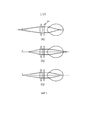
Фиг. 1 - изображение, поясняющее принцип Шейнера, который является принципом всех известных рефрактометров.FIG. 1 is an image explaining the Scheiner principle, which is the principle of all known refractometers.
Фиг. 2 - известная схема.FIG. 2 is a known diagram.
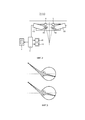
Фиг. 3 - изображение, поясняющее автоотражение или ретроотражение.FIG. 3 is an image explaining auto-reflection or retroreflection.
Фиг. 4 - система и способ в соответствии с изобретением.FIG. 4 shows a system and method in accordance with the invention.
Фиг. 5A, 5B и 5C - возможные схемы устройства и способа в соответствии с изобретением.FIG. 5A, 5B and 5C are possible diagrams of a device and method in accordance with the invention.
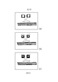
Фиг. 6 - изображение отражения тест-картины на сетчатке, фиксируемого на датчике изображения камеры, когда тест-картину перемещают на протяжении некоторого диапазона.FIG. 6 is a reflection image of a test pattern on the retina fixed to the camera image sensor when the test pattern is moved over a certain range.
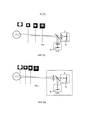
Фиг. 7A-7С - варианты осуществления системы в соответствии с изобретением.FIG. 7A-7C are embodiments of a system in accordance with the invention.
Фиг. 8 - изображение, поясняющее, что систему можно применить для распознавания, сфокусирован ли глаз на бесконечности.FIG. 8 is a view illustrating that the system can be used to recognize whether the eye is focused at infinity.
Фиг. 9 - схема, поясняющая поворот фокальных плоскостей.FIG. 9 is a diagram explaining the rotation of focal planes.
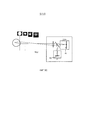
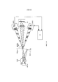
Фиг. 10 - схема дополнительного варианта осуществления системы и способа в соответствии с изобретением.FIG. 10 is a diagram of an additional embodiment of a system and method in accordance with the invention.
Фигуры вычерчены не в масштабе. В общем, идентичные компоненты обозначены одинаковыми числовыми на фигурах.The figures are not drawn to scale. In general, identical components are denoted by the same numeric in the figures.
ПОДРОБНОЕ ОПИСАНИЕ ПРЕДПОЧТИТЕЛЬНЫХ ВАРИАНТОВ ОСУЩЕСТВЛЕНИЯDETAILED DESCRIPTION OF THE PREFERRED EMBODIMENTS
На фиг. 1 поясняется принцип Шейнера, который является принципом всех известных рефрактометров.In FIG. 1 illustrates the Scheiner principle, which is the principle of all known refractometers.
Перед маской Ma с двумя точечными отверстиями размещен внешний объектив с фокальной точкой F. Только в случае правильной аккомодации оба пятна сливаются на сетчатке с образованием одного единственного, более яркого пятна (случай обозначен (c)).An external lens with a focal point F is placed in front of the Ma mask with two pinholes. Only in case of proper accommodation do both spots merge on the retina with the formation of one single, brighter spot (the case is indicated by (c)).
На фиг. 2 изображен оптометр, предложенный Окуямой.In FIG. 2 shows the optometer proposed by Okuyama.
Перед левым L и правым R глазами установлены дихроичные зеркала M1 и M2 и используются левый и правый оптометры O1 и O2. Сигналы передаются в блок С управления, который может передавать выходной сигнал в перьевой самописец P, монитор M и/или телевизионный приемник TV.In front of the left L and right R eyes, dichroic mirrors M1 and M2 are installed and the left and right optometers O1 and O2 are used. The signals are transmitted to the control unit C, which can transmit the output signal to the pen recorder P, monitor M and / or television receiver TV.
Очевидно, что хотя авторефрактометр Окуямы обеспечивает наблюдение естественных объектов наблюдения, помеха от полупрозрачных зеркал около глаз и потребность в фиксаторе подбородка не создают ощущения естественного наблюдения.Obviously, although the Okuyama autorefractometer provides observation of natural objects of observation, the interference from translucent mirrors near the eyes and the need for a chin restraint do not create a sensation of natural observation.
Целью изобретения является создание возможности удаленного определения расстояния фокусирования линзовых систем формирования изображения с большого расстояния.The aim of the invention is to provide the ability to remotely determine the focusing distance of lens imaging systems from a large distance.
С данной целью система в соответствии с изобретением содержит светопроекционное устройство для проецирования, по меньшей мере, одной оптической тест-картины и средство для обеспечения, по меньшей мере, одной тест-картины на, по меньшей мере, одной известной фокальной плоскости, и камеру, имеющую оптическую ось, совпадающую, по меньшей мере, частично, с оптической осью проекционного устройства, для измерения изображения отражения, по меньшей мере, одной оптической тест-картины на плоскости изображения объектива, и процессор изображений для анализа резкости, по меньшей мере, одной отраженной тест-картины.To this end, the system in accordance with the invention comprises a light projection device for projecting at least one optical test picture and means for providing at least one test picture on at least one known focal plane, and a camera, having an optical axis coinciding, at least partially, with the optical axis of the projection device for measuring the reflection image of at least one optical test pattern on the image plane of the lens, and an image processor for Analysis of field of at least one of the reflected test pattern.
Поскольку изобретение пригодно для работы с (человеческими) глазами, данное изобретение обеспечивает фокусное расстояние, до которого происходит аккомодация, что показывает расстояние до объекта, на который кратковременно обращено внимание.Since the invention is suitable for working with (human) eyes, this invention provides the focal length to which accommodation occurs, which shows the distance to the object that is briefly paid attention to.
В противоположность существующим системам для измерения аккомодации глаз изобретение является совершенно не беспокоящим, так что аккомодацию измеряют без вынужденного создания помех наблюдению от полупрозрачной оптики в пути наблюдения или от элементов на периферии глаза.In contrast to existing systems for measuring eye accommodation, the invention is completely non-disturbing, so accommodation is measured without having to interfere with observation from translucent optics in the observation path or from elements on the periphery of the eye.
В противоположность существующим системам для измерения аккомодации глаз предложенная система может быть конструктивно выполнена с небольшим форм-фактором, обычно, в размер сверхминиатюрного проектора или веб-камеры.In contrast to existing systems for measuring accommodation of the eyes, the proposed system can be structurally designed with a small form factor, usually the size of an ultra-miniature projector or webcam.
Простая конструкция оптики и потенциально простое определение надлежащего фокуса допускает недорогое исполнение.The simple design of the optics and the potentially simple determination of the proper focus allows for inexpensive performance.
Использование тест-картин, известных блоку обработки изображений, делает определение фокуса, по существу, устойчивым к движению, так как конкретная тест-картина в фокусе всегда будет передаваться обратно глазом в, приблизительно, одно и то же местоположение в кадре коаксиальной камеры. Данное свойство обусловлено просто коаксиальной геометрией. Данное свойство делает систему также устойчивой к размытости вследствие движения.The use of test patterns known to the image processing unit makes the determination of focus substantially resistant to movement, since a particular test pattern in focus will always be transmitted back by the eye to approximately the same location in the frame of the coaxial camera. This property is due simply to coaxial geometry. This property makes the system also resistant to motion blur.
Использование нескольких тест-картин, как поясняется в вариантах осуществления, должно также обеспечивать возможность одновременного определения по отдельности аккомодации глаз нескольких обследуемых человек.The use of several test patterns, as explained in the embodiments, should also enable the simultaneous determination of individually accommodating the eyes of several examined individuals.
На фиг. 3 поясняется принцип ретроотражения. Эффект красных глаз, т.е. отражения от сетчатки, является относительно независимым от направления взгляда; при этом объекту обследования не обязательно смотреть в направлении камеры или соседней импульсной лампы. Источник света создает яркую проекцию на сетчатку. Так как объект обследования, обычно, фокусируется на камере или импульсной лампе, то свет эффективно концентрируется на сетчатке, из-за чего пятно источника света на сетчатке действует как вторичный источник света, проецирующийся из глаза наружу к источнику света. Как следует из принципа Ферма, сопряженные точки источника света и изображения источника света в изображении на сетчатке совпадают между собой, независимо от направления распространения света, так что изображение отражения источника света от сетчатки и источника света находятся в одной и той же точке. Вследствие этого, глаз обладает естественным свойством ретроотражения.In FIG. 3 explains the principle of retroreflection. Red eye effect i.e. reflection from the retina, is relatively independent of the direction of view; however, the object of the survey does not have to look in the direction of the camera or an adjacent flash lamp. The light source creates a bright projection on the retina. Since the object of examination is usually focused on the camera or a flash lamp, the light is effectively concentrated on the retina, due to which the spot of the light source on the retina acts as a secondary light source, projecting from the eye outward to the light source. As follows from the Fermat principle, the conjugate points of the light source and the image of the light source in the image on the retina coincide with each other, regardless of the direction of light propagation, so that the image of the reflection of the light source from the retina and the light source are at the same point. As a result, the eye has a natural retroreflection property.
На фиг. 4 представлены система и способ в соответствии с изобретением.In FIG. 4 shows a system and method in accordance with the invention.
Проектор P и камера CAM имеют общую оптическую ось, т.е. оси AXCAM и AXP совпадают, вследствие применения делителя BSP пучка, который может быть полупрозрачным зеркалом. Проектор проецирует тест-картину таким образом, что каждая точка A1 тест-картины P1 проецируется в точку A2 так, что совокупность точек тест-картины формирует резкое изображение данной тест-картины в фокальной плоскости FPL1. Проектор и камера снабжены объективами L1 и L2, соответственно.The projector P and the CAM camera share a common optical axis, i.e. the axes AXCAM and AXP coincide, due to the use of the BSP beam splitter, which can be a translucent mirror. The projector projects the test pattern in such a way that each point A1 of the test pattern P1 is projected to point A2 so that the plurality of points of the test pattern forms a sharp image of the test pattern in the focal plane FPL1. The projector and camera are equipped with lenses L1 and L2, respectively.
Если в фокальной плоскости проектора установить экран, то камера сможет записать проекцию A2, которая будет представляться только в виде единственной точки A5 на датчике, если его фокальная плоскость совпадает с фокальной плоскостью проектора. Однако экран отсутствует. В отсутствие физического проекционного экрана удаленная система формирования изображения, в настоящем случае глаз EYE, будет фокусировать точку A2 на сетчатке в точке A3 и будет передавать через точку A4 точку обратно в камеру в точку A5, при условии, что точка A2 оказывается расположенной в фокальной плоскости удаленной системы формирования изображения, в настоящем случае глаза, т.е. на фокальной плоскости FPL2.If you install a screen in the focal plane of the projector, the camera will be able to record the projection A2, which will be presented only as a single point A5 on the sensor, if its focal plane coincides with the focal plane of the projector. However, the screen is missing. In the absence of a physical projection screen, the remote imaging system, in the present case, the EYE eye, will focus point A2 on the retina at point A3 and will transmit through point A4 the point back to the camera at point A5, provided that point A2 is located in the focal plane remote imaging system, in the present case, the eyes, i.e. on the focal plane FPL2.
На фиг. 4, удаленный глаз сфокусирован на пространственной точке B1, которая, следовательно, расположена в мгновенной фокальной плоскости FPL2 глаза (следует отметить, что реальная фокальная плоскость глаза будет фокальной поверхностью с некоторой кривизной). При этом фокальная плоскость глаза совпадает с фокальной плоскостью FPL1 камеры и проектора. В результате, на сетчатке глаза формируется резкое изображение. На практике, вся проецируемая тест-картина будет передаваться обратно в фокусе, так как глубина резкости каждой из трех систем формирования изображения, обычно, вытягивает зону совмещенного фокуса в 3-мерный объем вблизи двух фокальный плоскостей. Разумеется, объем совмещенного фокуса уменьшается, когда угол между двумя оптическими осями увеличивается.In FIG. 4, the distant eye is focused on the spatial point B1, which, therefore, is located in the instantaneous focal plane FPL2 of the eye (it should be noted that the real focal plane of the eye will be a focal surface with some curvature). In this case, the focal plane of the eye coincides with the focal plane FPL1 of the camera and the projector. As a result, a sharp image forms on the retina. In practice, the entire projected test picture will be transmitted back into focus, since the depth of field of each of the three imaging systems usually draws the combined focus area into a 3-dimensional volume near two focal planes. Of course, the volume of the combined focus decreases when the angle between the two optical axes increases.
Определение фокуса основано на том, что проецируемая тест-картина или, по меньшей мере, ракурс проецируемой тест-картины (например, ориентация) известна(известен) блоку обработки изображений. Для определения нахождения фокуса в предварительно заданной плоскости удаленная система формирования изображения, т.е. глаз, будет передавать фрагмент тест-картины обратно в камеру, как будто данный фрагмент проецировался на физический экран на таком же расстоянии. Проще говоря, только в случае, если фокальные плоскости глаза и фокальная плоскость проектора и камеры совпадают, камера будет записывать резкое ретроотражение тест-картины на сетчатке. На фиг. 4 показано, что между глазом EYE и фокальной плоскостью FPL2 глаза ничего не расположено. Измерение аккомодации глаз выполняется удаленно. Обследуемый человек не должен ни смотреть в измерительное устройство или использовать полупрозрачное зеркало, расположенное перед глазами, ни пользоваться фиксатором подбородка. Способ является совершенно не беспокоящим и, при использовании ИК-света, может применяться даже без предупреждения человека об обследовании. Ниже приведены примеры использования видимого света, который, тем не менее, не будет восприниматься наблюдателем или, по меньшей мере, не будет раздражать наблюдателя. В настоящим примере, глаз фокусируется в точке В1; изображение точки В1 находится в точке B2 на сетчатке, при этом, сетчатка является чувствительной поверхностью удаленной системы формирования оптического изображения, являющейся человеческим глазом.The definition of focus is based on the fact that the projected test picture or at least the angle of the projected test picture (for example, orientation) is known (known) to the image processing unit. To determine if the focus is in a predetermined plane, the remote imaging system, i.e. eye, will transmit a fragment of the test picture back to the camera, as if this fragment was projected onto the physical screen at the same distance. Simply put, only if the focal planes of the eye and the focal plane of the projector and camera coincide, the camera will record a sharp retroreflection of the test picture on the retina. In FIG. Figure 4 shows that nothing is located between the EYE eye and the focal plane FPL2 of the eye. Eye accommodation measurement is performed remotely. The examined person should neither look into the measuring device or use the translucent mirror located in front of the eyes, nor use the chin lock. The method is completely not disturbing and, when using infrared light, can be used even without warning a person about the examination. The following are examples of the use of visible light, which, however, will not be perceived by the observer or, at least, will not irritate the observer. In the present example, the eye focuses at point B1; the image of point B1 is located at point B2 on the retina, while the retina is the sensitive surface of the remote optical imaging system, which is the human eye.
Новый принцип определения фокуса по общей фокальной плоскости можно применить для оценки фокуса, или измерения фокуса, или отслеживания фокуса в пределах предварительно заданного диапазона фокусных расстояний. В случае применения определения фокуса в качестве основы существуют различные способы оценки или измерения фокуса в диапазоне фокусных расстояний.The new principle of determining focus from a common focal plane can be applied to evaluate focus, or measure focus, or track focus within a predefined range of focal lengths. In the case of applying the definition of focus as the basis, there are various ways of evaluating or measuring focus in the range of focal lengths.
Вариант осуществления изобретения, использующий одну проецируемую световую тест-картину, основан на комбинированной настройке общих фокусных расстояний проектора и камеры. При применении нового принципа определения фокуса общую фокальную плоскость проектора и камеры настраивают, пока не обнаруживают оптимальным образом проецируемую тест-картину из глаза, т.е. пока отражение тест-картины на сетчатке не становится максимально резким. Найденное таким образом значение общего фокусного расстояния показывает фокусное расстояние глаза. Ниже представлены варианты осуществления изобретения, использующие проецирование нескольких тест-картин, при этом все упомянутые варианты осуществления основаны на проецировании нескольких тест-картин, каждая из которых фокусируется на отличающемся расстоянии. Пока тест-картины находятся в пределах глубины резкости камеры, обнаружение конкретной тест-картины дает фокус на соответствующем расстоянии.An embodiment of the invention using a single projected light test pattern is based on a combined adjustment of the overall focal lengths of the projector and camera. When applying the new principle of determining the focus, the common focal plane of the projector and camera is adjusted until they find the optimal projected test picture from the eye, i.e. until the reflection of the test pattern on the retina becomes as sharp as possible. The value of the total focal length found in this way shows the focal length of the eye. Embodiments of the invention using projection of several test patterns are presented below, with all of the above-mentioned embodiments based on projection of several test patterns, each of which focuses on a different distance. As long as the test patterns are within the depth of field of the camera, detecting a particular test pattern gives focus at the appropriate distance.
Камера CAM содержит датчик IS изображения. Сигналы датчика IS изображения передаются в блок IP обработки изображений для измерения резкости изображения.The CAM camera contains an image sensor IS. The signals of the image sensor IS are transmitted to the image processing unit IP for measuring image sharpness.
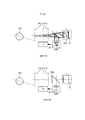
На фиг. 5A, 5B и 5C приведены возможные схемы устройства в соответствии с изобретением.In FIG. 5A, 5B and 5C show possible circuitry of a device in accordance with the invention.
На фиг. 5A проектор и камера имеют по отдельному объективу, на фиг. 5B проектор и камера имеют общий объектив. Данное решение уменьшает число элементов системы.In FIG. 5A, the projector and the camera have a separate lens; FIG. The 5B projector and camera share a common lens. This solution reduces the number of system elements.
На фиг. 5C камера и проектор поменялись местами расположения по сравнению с фиг. 5B. Данный вариант осуществления предпочтителен. Для камеры целесообразно обеспечить прямую линию наблюдения через делитель пучка. Разумеется, камеру и проектор на фиг. 5A также можно поменять местами.In FIG. 5C, the camera and the projector are swapped compared to FIG. 5B. This embodiment is preferred. It is advisable for the camera to provide a direct line of observation through the beam splitter. Of course, the camera and projector in FIG. 5A can also be swapped.
На фиг. 5A-5C показаны также снятые камерой изображения тест-картины, отраженной от сетчатки глаза. Когда фокальная плоскость FLP2 глаза совпадает с фокальной плоскостью проектора и камеры, наблюдается сравнительно резкое изображение, при этом упомянутое изображение постепенно размывается по мере того, как фокальная плоскость глаза расходится с фокальной плоскостью проектора и камеры. Наблюдаемые изображения были сняты коаксиальной камерой во время изменения ее фокуса, при статическом фокусе внешней системы формирования изображения (указанной как глаз на чертеже). При перемещении фокальной плоскости проектора и камеры на протяжении некоторого диапазона и одновременной записи изображения использование обработки изображений для определения резкости изображения обеспечивает максимум резкости в конкретной фокальной плоскости проектора и камеры. Фокальная плоскость глаза соответствует найденной таким образом фокальной плоскости.In FIG. 5A-5C also show camera images of a test pattern reflected from the retina. When the focal plane FLP2 of the eye coincides with the focal plane of the projector and the camera, a relatively sharp image is observed, and the image is gradually blurred as the focal plane of the eye diverges from the focal plane of the projector and camera. The observed images were taken with a coaxial camera during a change in its focus, with the static focus of an external imaging system (indicated as an eye in the drawing). When moving the focal plane of the projector and camera over a certain range and simultaneously recording the image, the use of image processing to determine the sharpness of the image provides maximum sharpness in the specific focal plane of the projector and camera. The focal plane of the eye corresponds to the focal plane found in this way.
Тест-картину можно обеспечивать в инфракрасном (ИК) свете.The test picture can be provided in infrared (IR) light.
В предпочтительных вариантах осуществления, тест-картину можно также обеспечивать в каждом чередующемся видеокадре с тем, чтобы камера поочередно получала фоновое изображение и изображение с проекцией световых тест-картин. Вычитание фонового изображение оставляет только отражение световой тест-картины на сетчатке, что значительно повышается способность к обнаружению отражения тест-картины.In preferred embodiments, a test pattern can also be provided in each alternating video frame so that the camera alternately receives a background image and a projection image of light test patterns. Subtraction of the background image leaves only the reflection of the light test pattern on the retina, which greatly increases the ability to detect reflection of the test pattern.
В предпочтительных вариантах осуществления тест-картине можно также придать временную частоту, например 70 Гц. В предпочтительном варианте частота не соответствует, например, частоте, используемой другими источниками видимого или инфракрасного света. Тогда, камера может быть настроена на данную частоту с использованием частотного фильтра для отфильтровывания ИК-сигналов, которые не находятся в диапазоне частот около частоты проектора. В данных предпочтительных вариантах осуществления отфильтровываются фоновые сигналы.In preferred embodiments, the implementation of the test pattern can also be given a temporary frequency, for example 70 Hz. In a preferred embodiment, the frequency does not correspond, for example, to the frequency used by other sources of visible or infrared light. Then, the camera can be tuned to a given frequency using a frequency filter to filter out IR signals that are not in the frequency range near the frequency of the projector. In these preferred embodiments, background signals are filtered out.
На фиг. 6 показано отражение тест-картины на сетчатке, фиксируемое на датчике изображения камеры, когда тест-картину перемещают на протяжении некоторого диапазона.In FIG. Figure 6 shows the reflection of the test pattern on the retina, fixed on the camera image sensor, when the test pattern is moved over a certain range.
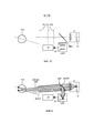
На фиг. 7A-7С изображены варианты осуществления системы и способа в соответствии с изобретением. Различие между данным вариантом осуществления и предыдущим вариантом осуществления состоит в том, что несколько фокальных плоскостей FPLi-FPLj сформировано с использованием микролинзового растра. Система в соответствии с данными вариантами осуществления содержит микролинзовый растр MAR, размещенный в оптическом пути проектора для создания светового поля, которое содержит разные тест-картины, каждая из которых сфокусирована на отличающемся расстоянии. При применении такого метода можно создать либо ряд дискретно сфокусированных тест-картин, либо непрерывную тест-картину, известный ракурс которой изменяется в зависимости от расстояния. Данная тест-картина может быть решетчатой картиной; тогда ориентацию тест-картины можно использовать как известный ракурс тест-картины. Посредством анализа изображения на камере можно находить фокальную плоскость глаза. Одновременное проецирование на разных расстояниях позволяет также оценивать аккомодацию глаз по отдельности нескольких объектов обследования в пределах диапазона системы. Упомянутая возможность отсутствует в известных системах.In FIG. 7A-7C illustrate embodiments of a system and method in accordance with the invention. The difference between this embodiment and the previous embodiment is that several focal planes FPLi-FPLj are formed using a microlens raster. The system in accordance with these options for implementation contains a micro-raster raster MAR located in the optical path of the projector to create a light field that contains different test patterns, each of which is focused at a different distance. Using this method, you can create either a series of discretely focused test patterns or a continuous test pattern, the known angle of which varies with distance. This test picture may be a lattice picture; then the orientation of the test picture can be used as a known perspective of the test picture. By analyzing the image on the camera, you can find the focal plane of the eye. Simultaneous projection at different distances also allows you to evaluate the accommodation of the eyes separately of several objects of examination within the range of the system. The mentioned possibility is absent in known systems.
На фиг. 7A микролинзовый растр расположен в оптическом пути проектора, однако, аналогичные результаты получают при размещении микролинзового растра в оптическом пути камеры, причем в таком случае вместо пленоптического проектора применяют пленоптическую камеру. Упомянутая схема расположения схематично показана на фиг. 7С. В предпочтительных вариантах осуществления, микролинзовый растр устанавливают как перед камерой, так и перед проектором, что схематично показано на фиг. 7B. Последняя схема расположения обеспечивает отношение 1:1 между пикселями проектора и камеры, что дает преимущество.In FIG. 7A, the microlens raster is located in the optical path of the projector, however, similar results are obtained by placing the microlens raster in the optical path of the camera, in which case a plenoptic camera is used instead of the plenoptic projector. Said arrangement is shown schematically in FIG. 7C. In preferred embodiments, a microlens raster is mounted both in front of the camera and in front of the projector, as shown schematically in FIG. 7B. The latter arrangement provides a 1: 1 ratio between the pixels of the projector and the camera, which gives an advantage.
Вместо микролинзового растра проектор может содержать ряд разных слайдов на разных расстояниях позади объектива проектора, при этом каждый из упомянутых слайдов имеет отличающуюся тест-картину.Instead of a microlens raster, the projector may contain a series of different slides at different distances behind the projector lens, with each of these slides having a different test picture.
Маска тест-картины может быть также дифракционным элементом, формирующим световое поле с разными характеристиками на разных расстояниях. Для данной цели можно воспользоваться голограммой.The test pattern mask can also be a diffraction element forming a light field with different characteristics at different distances. For this purpose, you can use the hologram.
Формирование тест-картины (или тест-картин) на нескольких расстояниях можно также производить последовательно во времени, при условии, что камера использует синхронизированную фиксацию изображений.The formation of a test picture (or test picture) at several distances can also be performed sequentially in time, provided that the camera uses synchronized image capture.
Возможно также использование, по меньшей мере, двух проекторов, проецирующих статические тест-картины на разных расстояниях, с применением зеркал для расположения оптических осей проекторов на одной прямой.It is also possible to use at least two projectors projecting static test patterns at different distances, using mirrors to position the optical axes of the projectors on one straight line.
При наличии подходящей тест-картины размытие тест-картины может моментально идентифицировать направление, в котором ее проекция находится не в фокусе. Данную возможность можно использовать для механического управления фокусом проектора (и камеры), чтобы сохранить в фокусе передаваемую тест-картину. Затем система управления автоматически определяет фокусное расстояние неизвестной системы, т.е. фокальную плоскость глаза. Неудобство состоит в том, что упомянутая система может подстраиваться к единственной неизвестной камере или одному обследуемому человеку; в противоположность применению одновременного проецирования нескольких тест-картин. В настоящей заявке описаны система и способ для отслеживания аккомодации глаза, однако, следует отметить, что камера функционирует подобно глазу, и поэтому систему можно также применять для отслеживания фокуса камеры.With a suitable test picture, blurring the test picture can instantly identify the direction in which its projection is out of focus. This feature can be used to mechanically control the focus of the projector (and camera) to keep the transmitted test picture in focus. Then, the control system automatically determines the focal length of the unknown system, i.e. focal plane of the eye. The inconvenience is that the system can be adjusted to a single unknown camera or to one person being examined; as opposed to using the simultaneous projection of several test patterns. A system and method for tracking eye accommodation is described herein, however, it should be noted that the camera functions like an eye, and therefore, the system can also be used to track the focus of the camera.
Система способна также определять, когда глаз фокусируется на бесконечность. Даже несмотря на то, что фокальная плоскость проектора и фокальная плоскость глаза могут не совпадать в данной ситуации, изображение тест-картины на датчике камеры все же будет сформировано резко, когда глаз фокусируется на бесконечность. На фиг. 8 изображена такая ситуация. Параллельные световые лучи, испускаемые проектором, фокусируются глазом при фокусировке на бесконечность на сетчатке, и световые лучи, отраженные от сетчатки, формируют параллельные лучи, которые фокусируются на датчике камеры. Таким образом, система способна устанавливать, фокусируется ли глаз или нет на бесконечность.The system is also able to determine when the eye focuses on infinity. Even though the focal plane of the projector and the focal plane of the eye may not coincide in this situation, the image of the test picture on the camera’s sensor will still be sharply formed when the eye focuses on infinity. In FIG. 8 depicts such a situation. The parallel light rays emitted by the projector are focused by the eye when focusing on infinity on the retina, and the light rays reflected from the retina form parallel rays that focus on the camera sensor. Thus, the system is able to determine whether the eye focuses or not on infinity.
В ситуации, когда тест-картины формируются в различных фокальных плоскостях, одна тест-картина может быть предназначена для бесконечности. Способы измерения резкости известны. Один способ измерения резкости состоит, например, в измерении протяженности линий в тест-картине и/или отношения между максимумами и минимумами в отраженной тест-картине. Протяженность линий в тест-картине будет минимальной, а отношение будет максимальным, когда тест-картина сфокусирована, т.е. является резкой.In a situation where test patterns are formed in different focal planes, one test pattern can be designed for infinity. Methods for measuring sharpness are known. One way to measure sharpness is, for example, to measure the length of the lines in the test pattern and / or the relationship between the highs and lows in the reflected test pattern. The length of the lines in the test picture will be minimal, and the ratio will be maximum when the test picture is focused, i.e. is sharp.
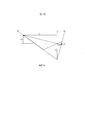
Кроме того, как упоминалось выше, объем совмещенного фокуса уменьшается, когда угол между двумя оптическими осями, оптической осью глаза и оптической осью проектора и камеры увеличивается. Данный поворот можно скомпенсировать поворотом фокальной плоскости проектора и, при необходимости, камеры. На фиг. 9 поясняется поворот фокальной плоскости проектора. Данный поворот обеспечивают поворотом плоскости изображения относительно плоскости объектива, известным как конфигурация Шаймпфлюга, впервые предложенная Теодором Шаймпфлюгом, смотри, например, патент Великобритании (GB) № 1196 от мая 1904 г. Упомянутая наклонная геометрия объектива, названная именем ее автора, обуславливает приобретение фокальной плоскостью поворота относительно плоскости объектива. Продолженная фокальная плоскость будет пересекать продолженную плоскость объектива, а также продолженную плоскость изображения по одной линии. В альтернативном варианте можно использовать несколько пар из проектора и камеры, направленных линией наблюдения на глаз и для наблюдения глазом и анализирующих различные отраженные тест-картины.In addition, as mentioned above, the volume of the combined focus decreases when the angle between the two optical axes, the optical axis of the eye, and the optical axis of the projector and camera increases. This rotation can be compensated by turning the focal plane of the projector and, if necessary, the camera. In FIG. 9 illustrates the rotation of the focal plane of the projector. This rotation is ensured by rotation of the image plane relative to the lens plane, known as the Scheimpflug configuration, first proposed by Theodor Scheimpflug, see, for example, UK patent (GB) No. 1196 of May 1904. The mentioned oblique geometry of the lens, named after its author, determines the acquisition of the focal plane rotation relative to the plane of the lens. The extended focal plane will intersect the extended lens plane, as well as the extended image plane in a single line. Alternatively, you can use several pairs from the projector and camera, directed by the line of observation on the eye and for observation by the eye and analyzing various reflected test patterns.
В примере изобретения, приведенном на фиг. 10, проектор окружен группой камер, Cam 1, Cam 2 и т.п. При использовании группы камер можно создать световое поле в центре группы. При использовании изображений, обеспечиваемых группой камер, можно реконструировать изображения с различной глубиной резкости. Данное решение позволяет получать информацию о глубине по изображениям, снятым группой камер. Преимущество приведенного способа состоит в том, что никакой информацией о глубине не требуется располагать заранее. Положение глаза можно получить путем анализа изображений группы камер.In the example of the invention shown in FIG. 10, the projector is surrounded by a group of cameras,
Систему и способ в соответствии со всеми вариантами осуществления можно применять для отслеживания показателей жизненно важных функций:The system and method in accordance with all options for implementation can be used to track indicators of vital functions:
Известно, что когда люди продолжают фокусироваться на фиксированное расстояние, данная стационарная аккомодация глаз изменяется периодически с дыханием, а также с сокращениями сердца. По существу, определение аккомодации может также обеспечивать упомянутые показатели жизненно важных функций. Тот факт, что система в соответствии с изобретением может выполнять данную задачу без причинения беспокойства и дистанционно, предлагает ранее недостижимые возможности. Например, когда требуется измерять частоту сердечных сокращений и периодичность дыхания человека, который проходит испытание на выносливость, данное измерение можно выполнять без беспокойства человека проводами.It is known that when people continue to focus on a fixed distance, this stationary accommodation of the eyes changes periodically with breathing, as well as with heart contractions. Essentially, the definition of accommodation can also provide the mentioned indicators of vital functions. The fact that the system in accordance with the invention can accomplish this task without causing concern and remotely offers previously unattainable opportunities. For example, when you want to measure the heart rate and the frequency of breathing of a person who is undergoing an endurance test, this measurement can be performed without disturbing the person with wires.
С другой стороны, при обеспечении извне измеренных показателей жизненно важных функций, измерение аккомодации глаз можно, в принципе, корректировать с учетом изменения расстояния фокусировки, которое вызывают упомянутые показатели.On the other hand, while providing the measured parameters of vital functions from outside, the measurement of eye accommodation can, in principle, be adjusted taking into account the change in the focusing distance that these indicators cause.
Применяемая камера может быть камерой светового поля, т.е. камерой, которая способна обеспечивать данные изображения, которые можно использовать для формирования изображения, которое находится в фокусе в диапазоне глубин резкости. Существуют различные способы преобразования обычной камеры в камеру светового поля с синтезированной апертурой. Преимущество камеры светового поля состоит в том, что данная камера фиксирует за одну экспозицию полное поле световых лучей, из которого можно ретроспективно настраивать фокус или диапазон фокусировки по единственному зафиксированному кадру. По существу, зафиксированное световое поле мгновенно обеспечивает оценку или измерение фокусного расстояния удаленного(ных) глаза или глаз. Упомянутую камеру можно конструктивно выполнить с использованием микролинзового растра перед датчиком, с использованием кодированной апертуры или модулирующей картины в оптическом пути между объективом и датчиком (так называемая, пятнистая фотография).The camera used may be a light field camera, i.e. a camera that is capable of providing image data that can be used to form an image that is in focus in the range of depth of field. There are various methods for converting a conventional camera to a synthesized aperture light field camera. The advantage of the light field camera is that this camera captures the entire field of light rays in one exposure, from which you can retrospectively adjust the focus or focus range for a single fixed frame. Essentially, a fixed light field instantly provides an estimate or measurement of the focal length of the distant eye (s). The said camera can be structurally performed using a microlens raster in front of the sensor, using a coded aperture or a modulating picture in the optical path between the lens and the sensor (so-called spotted photo).
Существуют различные способы продолжения глубины резкости камеры, без ущерба для экспонирования. В упомянутых способах особенно заинтересованы, когда камеру используют только для обнаружения конкретных тест-картин, а не для обычной фиксации изображения. Известным способом является применение формирования изображений с перемещением фокуса.There are various ways to continue the depth of field of the camera, without compromising exposure. These methods are especially interested when the camera is used only for the detection of specific test patterns, and not for conventional image capture. A known method is the use of imaging with moving focus.
В вариантах осуществления изобретения определение фокуса применяют в сочетании с определением взгляда.In embodiments of the invention, the definition of focus is used in conjunction with the definition of gaze.
При сочетании определения взгляда и определения фокуса появляется возможность устранять неоднозначность толкования ненамеренного взгляда и намеренного взгляда в направлении устройства. В приведенном случае система является частью конкретного устройства, которым следует управлять по взгляду, возможно, в сочетании с другим пусковым сигналом, исходящим от кнопки или интерпретатора речевой команды.With the combination of the definition of gaze and the definition of focus, it becomes possible to eliminate the ambiguity in the interpretation of involuntary gaze and intentional gaze towards the device. In this case, the system is part of a specific device that should be controlled by sight, possibly in combination with another trigger signal coming from a button or interpreter of a speech command.
В частности, посредством выбора расположения проецируемой фокальной плоскости в самом устройстве можно определять намеренный фокус в дополнение к взгляду. Случай, когда взгляд определен без определения надлежащего фокуса, можно считать ненамеренным взглядом и не принимать во внимание в качестве пускового сигнала для начала управления устройством.In particular, by selecting the location of the projected focal plane in the device itself, it is possible to determine the intentional focus in addition to the gaze. The case when the gaze is determined without determining the proper focus can be considered an unintentional gaze and not be taken into account as a trigger signal to start controlling the device.
Так как определение взгляда уже основано на использовании камеры и коаксиального (инфракрасного) освещения, то определение взгляда и определение фокуса можно эффективно объединять при небольших дополнительных затратах.Since the definition of gaze is already based on the use of a camera and coaxial (infrared) illumination, the determination of gaze and determination of focus can be effectively combined at a small additional cost.
Использование определения или оценки фокуса в сочетании с оценкой взгляда.The use of a definition or assessment of focus combined with an assessment of gaze.
Сочетание с оценкой взгляда позволяет определять точку направления взгляда в 3-мерном пространстве. Сочетание с (голографическим) 3-мерным дисплеем может предоставить уникальные функциональные возможности.The combination with the assessment of the gaze allows you to determine the point of direction of the gaze in 3-dimensional space. Combination with a (holographic) 3-dimensional display can provide unique functionality.
Систему и способ в соответствии с изобретением можно применять в различных практических областях.The system and method in accordance with the invention can be applied in various practical fields.
Удаленную оценку аккомодации глаз у людей можно применить для измерения внимания, для измерения визуального внимания к смыслу цифровых указателей, возможно, в сочетании с определением взгляда. Знание расстояния фокусировки может способствовать различению между «видением» и «пристальным разглядыванием».A remote assessment of eye accommodation in people can be used to measure attention, to measure visual attention to the meaning of digital pointers, possibly in combination with the definition of gaze. Knowing the focusing distance can help distinguish between "vision" and "close looking."
Возможно, в сочетании с определением взгляда систему и способ можно также применять как внимательный пользовательский интерфейс, который реагирует на речевую команду или на действие только в том случае, когда на него смотрят.Perhaps, in combination with determining the gaze, the system and method can also be used as an attentive user interface that responds to a speech command or action only when it is looked at.
Удаленное измерение аккомодации глаз можно также применить при определении дефектов зрения у детей, для контроля правильного развития зрительной системы.Remote measurement of eye accommodation can also be used to determine visual defects in children, to monitor the proper development of the visual system.
Определение аккомодации на бесконечность может обнаруживать, достаточно ли водитель сфокусирован на дороге.Infinity detection can detect if the driver is sufficiently focused on the road.
Как часть управляемого взглядом пользовательского интерфейса для инвалидов, определение аккомодации может обеспечить ошибкоустойчивость, например, при управлении мышью.As part of the gaze-driven user interface for the disabled, the definition of accommodation can provide error tolerance, for example, when controlling a mouse.
В сочетании с оптической системой, определение аккомодации может обеспечить способ автоматической адаптации оптической системы к состоянию преломления глаза. Так как способ работает без причинения беспокойства и обеспечивает небольшой форм-фактор, то применение может выходить за пределы традиционной офтальмологии и может быть составной частью оптического изделия для потребительского рынка.In combination with the optical system, the determination of accommodation can provide a way to automatically adapt the optical system to the state of refraction of the eye. Since the method works without causing concern and provides a small form factor, the application may go beyond the scope of traditional ophthalmology and may be an integral part of the optical product for the consumer market.
В системах защиты определение фокуса зрения человека можно применять для обнаружения нежелательного внимания. Возможно также определение нежелательного фокуса камеры. Как упоминалось, систему можно также применять для измерения фокусного расстояния камеры.In security systems, determining a person’s focus of vision can be used to detect unwanted attention. It is also possible to detect unwanted camera focus. As mentioned, the system can also be used to measure the focal length of the camera.
Отсутствие беспокойства делает принцип особенно подходящим для применений с не сотрудничающими объектами обследования, например новорожденными, а также с (дикими) животными.The absence of anxiety makes the principle particularly suitable for applications with non-cooperating test subjects, such as newborns, as well as with (wild) animals.
Изобретение относится также к компьютерным программам, содержащим средство программного кода для выполнения способа в соответствии с изобретением в любом варианте осуществления, когда упомянутая программа выполняется в компьютере. Изобретение относится также к компьютерным программным продуктам, содержащим средство программного кода, хранящееся на компьютерно-считываемом носителе, для выполнения способа в соответствии с изобретением.The invention also relates to computer programs comprising program code means for executing a method in accordance with the invention in any embodiment when said program is executed in a computer. The invention also relates to computer software products comprising software code means stored on a computer-readable medium for carrying out the method in accordance with the invention.
Камера является любым устройством для записи изображений.A camera is any device for recording images.
Камера может быть частью устройства, применяемого также для других целей, например связи, или соединенной с упомянутым устройством связи, или встроенной в упомянутое устройство, или взаимодействующим с ним.The camera may be part of a device that is also used for other purposes, for example, communication, or connected to the said communication device, or integrated into the said device, or interacting with it.
Кроме того, дополнительный вариант осуществления относится к использованию световых тест-картин на разных длинах волн, например трех разных длинах волн, по одной на каждом конце диапазона видимого излучения и в центральной части диапазона видимого излучения, например красной-зеленой-синей. Измерение фокусных расстояний на трех длинах волн обеспечивает информацию об аберрации глаза. Фокусное расстояние можно измерять для каждой длины волны, причем данное измерение можно выполнять одновременно. Тем самым, выполняется мгновенное и удаленное измерение не просто аккомодации глаз, но также аккомодации глаз на трех разных длинах волн, т.е. аберрации.In addition, an additional embodiment relates to the use of light test patterns at different wavelengths, for example three different wavelengths, one at each end of the visible radiation range and in the central part of the visible radiation range, for example red-green-blue. Measuring focal lengths at three wavelengths provides information on eye aberration. The focal length can be measured for each wavelength, and this measurement can be performed simultaneously. Thus, an instantaneous and remote measurement is performed not just of the accommodation of the eyes, but also of the accommodation of the eyes at three different wavelengths, i.e. aberration.
Возможно также применение скрытых световых тест-картин, т.е. тест-картин, которые почти невидимы для человеческого глаза. Один из способов заключается в использовании ИК-света для световых тест-картин.It is also possible to use hidden light test patterns, i.e. test paintings that are almost invisible to the human eye. One way is to use infrared light for light test pictures.
Другой способ состоит в том, что тест-картину вставляют таким методом, который нельзя заметить человеческим глазом, в проецируемое изображение, по существу, не отвлекающее человеческий глаз.Another way is to insert a test picture in a way that cannot be seen by the human eye into a projected image that is essentially non-distracting to the human eye.
Проектор может проецировать однородную зону в белом свете плюс тест-картину в одном кадре и зону в белом свете минус упомянутую тест-картину в следующем кадре.The projector can project a homogeneous zone in white light plus a test picture in one frame and a zone in white light minus the test picture in the next frame.
В одном кадре проектор проецирует белый свет (с интенсивностью ниже максимальной) плюс тест-картину, в следующем кадре проектор проецирует белый свет минус тест-картину. Если частота кадров выше частоты, воспринимаемой человеческим глазом, то человеческий глаз будет воспринимать не тест-картину, а однородную лампу белого света, поскольку человек будет усреднять разность между двумя проекциями и, в результате, оставлять только однородную белую зону, видимую наблюдателем. Белые лампы освещения не притягивают внимание наблюдателя, и поэтому не мешают измерению. Однако при вычитании двух изображений, снятых камерой для двух кадров, отражение вставленной световой тест-картины может восприниматься в изображении, записанном камерой. Скрытые тест-картины, то есть скрытые для человеческого глаза, могут быть в проекторе разными для разных цветов, чем также можно воспользоваться, чтобы сделать тест-картины еще более невидимыми. Можно использовать, например, следующую последовательность:In one frame, the projector projects white light (with an intensity below the maximum) plus a test picture, in the next frame, the projector projects white light minus the test picture. If the frame rate is higher than the frequency perceived by the human eye, then the human eye will perceive not a test pattern, but a uniform white light lamp, since a person will average the difference between the two projections and, as a result, leave only a uniform white zone visible to the observer. White lighting lamps do not attract the attention of the observer, and therefore do not interfere with the measurement. However, when subtracting two images captured by the camera for two frames, the reflection of the inserted light test pattern may be perceived in the image recorded by the camera. Hidden test patterns, that is, hidden to the human eye, can be different for different colors in the projector, which can also be used to make test patterns even more invisible. You can use, for example, the following sequence:
I. Тест-картина в белом минус синем свете плюс тест-картина в зеленом свете, (при структурно различающихся тест-картинах),I. Test picture in white minus blue light plus test picture in green light, (with structurally different test pictures),
II. Тест-картина в белом минус зеленом света плюс тест-картина в красном свете,II. Test picture in white minus green light plus test picture in red light,
III. Тест-картина в белом плюс синем свете, минус тест-картина в красном свете.III. Test picture in white plus blue light, minus test picture in red light.
Сами тест-картины не обязательно должны быть одинаковыми, но могут различаться.Test patterns themselves do not have to be the same, but may vary.
Если частота кадров выше, чем, приблизительно 50 Гц, то глаз будет воспринимать лампу белого света. Однако камера может выделить отражение тест-картины в зеленом свете посредством вычитания II из I и получения «зеленого сигнала». Аналогично, камера может выделить отражение тест-картины в синем и красном свете посредством соответствующего вычитания кадров.If the frame rate is higher than about 50 Hz, the eye will perceive a white light lamp. However, the camera can highlight the reflection of the test pattern in green by subtracting II from I and obtaining a “green signal”. Similarly, the camera can highlight the reflection of the test pattern in blue and red light by correspondingly subtracting frames.
Другой способ формирования незаметных тест-картин заключается, например, в использовании тест-картин шахматной конфигурации в двух цветах (например, A-B), сумма которых дает белый цвет для человеческого глаза. Тест-картина шахматной конфигурации имеет вид A-B в одном кадре, B-A в следующем кадре. И вновь, человеческий глаз будет воспринимать белый свет, который не представляет тест-картины, но камера может выделять отражение тест-картин A и B посредством соответствующего вычитания или измерения кадров.Another way to create inconspicuous test patterns is, for example, to use test patterns of a chess configuration in two colors (for example, A-B), the sum of which gives a white color to the human eye. The test picture of the chess configuration looks like A-B in one frame, B-A in the next frame. Again, the human eye will perceive white light that does not represent the test pattern, but the camera can highlight the reflection of test patterns A and B through appropriate subtraction or frame measurements.
Еще один способ заключается в использовании тест-картины, которая содержит, по меньшей мере, три части разного цвета, (например, тест-картину сотовой конфигурации с цветами A-B-C). При использовании повторяющегося цикла из, по меньшей мере, трех кадров (A-B-C; C-A-B; B-C-A; A-B-C и т.п.), в котором человеческий глаз видит белый свет как усредненный по циклу во всех частях, любая первичная тест-картина не заметна для человеческого глаза.Another way is to use a test picture that contains at least three parts of different colors (for example, a test picture of a honeycomb configuration with A-B-C colors). When using a repeating cycle of at least three frames (ABC; CAB; BCA; ABC, etc.), in which the human eye sees white light as averaged over the cycle in all parts, any primary test picture is not noticeable for human eye.
Однако сигналы записывающей камеры можно анализировать для вычитания информации об отраженных тест-картинах в, по меньшей мере, трех цветах. Число цветов можно увеличить до четырех или более, для выделения более подробной информации об аберрациях.However, the signals of the recording camera can be analyzed to subtract information about the reflected test patterns in at least three colors. The number of colors can be increased to four or more, to highlight more detailed information about aberrations.
Способ можно использовать для обеспечения информации, например, о работе человеческого глаза различным образом. Например: посредством измерения реакции глаза или двух глаз наблюдателя, когда глаза следят за объектом, который перемещается в пределах поля зрения наблюдателя, можно получить информацию относительно диапазона расстояний, на которые глаз или глаза могут фокусироваться.The method can be used to provide information, for example, about the operation of the human eye in various ways. For example: by measuring the reaction of an eye or two eyes of an observer, when the eyes follow an object that moves within the field of view of the observer, information can be obtained regarding the range of distances that the eye or eyes can focus on.
В большинстве случаев можно просто запросить у человека упомянутую информацию. Однако существуют также случаи, когда такой запрос невозможен, так как человек не может обмениваться информаций и/или человек просто не может выдержать тесты, необходимые в ходе обычных процедур по причинам физического или психического состояния здоровья. Даже простое обеспечение обоснованной оценки параметров глаза предоставит, в результате, значительные преимущества, поскольку время и трудозатраты на получение качественных результатов для любого теста (и, следовательно, время, в течение которого пациент должен проходить тест) определяются, помимо прочего, отправным состоянием для тестов. Поэтому, небеспокоящее обеспечение удовлетворительного отправного состояния для более точных измерений может принести большую пользу пациенту.In most cases, you can simply ask the person for the information mentioned. However, there are also cases where such a request is not possible, since a person cannot exchange information and / or a person simply cannot pass the tests necessary during normal procedures for reasons of physical or mental health. Even the simple provision of a reasonable assessment of eye parameters will provide, as a result, significant advantages, since the time and labor required to obtain qualitative results for any test (and, therefore, the time during which the patient must undergo the test) are determined, among other things, by the starting state for the tests . Therefore, the non-disturbing provision of a satisfactory starting state for more accurate measurements can be of great benefit to the patient.
При измерении обоих глаз можно обнаружить и измерить различия между глазами, что может дать показание величины анизомерии. Изобретение можно, например, использовать для обеспечения показаний амблиопии в раннем возрасте посредством определения различий между глазами, когда ребенок, например, играет с игрушкой или смотрит на движущийся объект.When measuring both eyes, differences between the eyes can be detected and measured, which can give an indication of the magnitude of the anisomerism. The invention can, for example, be used to provide evidence of amblyopia at an early age by determining differences between the eyes when a child, for example, plays with a toy or looks at a moving object.
Изобретение можно вкратце изложить следующим образом:The invention can be summarized as follows:
Система и способ измеряют оптический фокус удаленной системы формирования оптического изображения, в частности аккомодацию глаз удаленного обследуемого человека. Световую тест-картину в оптическом излучении проецируют в фокусе в известной фокальной плоскости перед удаленной системой формирования оптического изображения и изображение отражения тест-картины на чувствительной поверхности удаленной системы формирования оптического изображения, например, на сетчатке глаза, записывают камерой, имеющей оптическую ось, по меньшей мере, частично совпадающую или расположенную близко с/к оптической осью/оси проекционного устройства. Определяют резкость световой картины, отраженной от чувствительной поверхности.The system and method measure the optical focus of a remote optical imaging system, in particular the accommodation of the eyes of a remote subject. A light test pattern in optical radiation is projected in focus in a known focal plane in front of the remote optical imaging system, and a reflection image of the test pattern on the sensitive surface of the remote optical imaging system, for example, on the retina of the eye, is recorded by a camera having an optical axis of at least partially coinciding or located close to / to the optical axis / axis of the projection device. The sharpness of the light pattern reflected from the sensitive surface is determined.
Claims (24)
Applications Claiming Priority (3)
| Application Number | Priority Date | Filing Date | Title |
|---|---|---|---|
| US201161507676P | 2011-07-14 | 2011-07-14 | |
| US61/507,676 | 2011-07-14 | ||
| PCT/IB2012/053369 WO2013008129A1 (en) | 2011-07-14 | 2012-07-03 | System and method for remote measurement of optical focus |
Publications (2)
| Publication Number | Publication Date |
|---|---|
| RU2014105469A RU2014105469A (en) | 2015-08-20 |
| RU2612500C2 true RU2612500C2 (en) | 2017-03-09 |
Family
ID=46682860
Family Applications (1)
| Application Number | Title | Priority Date | Filing Date |
|---|---|---|---|
| RU2014105469A RU2612500C2 (en) | 2011-07-14 | 2012-07-03 | System and method for remote measurement of optical focus |
Country Status (7)
| Country | Link |
|---|---|
| US (1) | US8934005B2 (en) |
| EP (1) | EP2731490B1 (en) |
| JP (1) | JP5571864B1 (en) |
| CN (1) | CN103648366B (en) |
| IN (1) | IN2014CN00418A (en) |
| RU (1) | RU2612500C2 (en) |
| WO (1) | WO2013008129A1 (en) |
Families Citing this family (31)
| Publication number | Priority date | Publication date | Assignee | Title |
|---|---|---|---|---|
| FR2997518B1 (en) * | 2012-10-30 | 2014-12-05 | Centre Nat Rech Scient | SELF-REFERENCE HOLOGRAPHIC IMAGING SYSTEM |
| US10271038B2 (en) * | 2013-01-15 | 2019-04-23 | Disney Enterprise, Inc. | Camera with plenoptic lens |
| US10107747B2 (en) * | 2013-05-31 | 2018-10-23 | Ecole Polytechnique Federale De Lausanne (Epfl) | Method, system and computer program for determining a reflectance distribution function of an object |
| US9480397B2 (en) | 2013-09-24 | 2016-11-01 | Sony Interactive Entertainment Inc. | Gaze tracking variations using visible lights or dots |
| US9781360B2 (en) | 2013-09-24 | 2017-10-03 | Sony Interactive Entertainment Inc. | Gaze tracking variations using selective illumination |
| US9468373B2 (en) * | 2013-09-24 | 2016-10-18 | Sony Interactive Entertainment Inc. | Gaze tracking variations using dynamic lighting position |
| US9836647B2 (en) * | 2013-10-08 | 2017-12-05 | Princeton Identity, Inc. | Iris biometric recognition module and access control assembly |
| JP6227996B2 (en) * | 2013-12-18 | 2017-11-08 | 浜松ホトニクス株式会社 | Measuring device and measuring method |
| US10425814B2 (en) | 2014-09-24 | 2019-09-24 | Princeton Identity, Inc. | Control of wireless communication device capability in a mobile device with a biometric key |
| CA2969331A1 (en) | 2014-12-03 | 2016-06-09 | Princeton Identity, Inc. | System and method for mobile device biometric add-on |
| US10043281B2 (en) | 2015-06-14 | 2018-08-07 | Sony Interactive Entertainment Inc. | Apparatus and method for estimating eye gaze location |
| EP3112922A1 (en) * | 2015-06-30 | 2017-01-04 | Thomson Licensing | A gaze tracking device and a head mounted device embedding said gaze tracking device |
| CN107851184B (en) * | 2015-07-28 | 2022-12-23 | 苹果公司 | System and method for light and image projection |
| JP2017079883A (en) * | 2015-10-23 | 2017-05-18 | 富士通株式会社 | Visual line detection system, visual line detection method, and visual line detection program |
| EP3403217A4 (en) | 2016-01-12 | 2019-08-21 | Princeton Identity, Inc. | Systems and methods of biometric analysis |
| WO2017167587A1 (en) | 2016-03-29 | 2017-10-05 | Koninklijke Philips N.V. | Unobtrusive fundus imaging |
| US10373008B2 (en) | 2016-03-31 | 2019-08-06 | Princeton Identity, Inc. | Systems and methods of biometric analysis with adaptive trigger |
| US10366296B2 (en) | 2016-03-31 | 2019-07-30 | Princeton Identity, Inc. | Biometric enrollment systems and methods |
| CN107788947A (en) * | 2016-09-07 | 2018-03-13 | 爱博诺德(北京)医疗科技有限公司 | Eye examination apparatus and method |
| CN106526576B (en) * | 2016-11-30 | 2019-02-15 | 上海卫星工程研究所 | Satellite remote sensing instrument ground imaging test optical axis alignment methods |
| US10607096B2 (en) | 2017-04-04 | 2020-03-31 | Princeton Identity, Inc. | Z-dimension user feedback biometric system |
| US10617567B2 (en) | 2017-06-10 | 2020-04-14 | Manjinder Saini | Intraocular implant device |
| US11547608B2 (en) * | 2017-06-10 | 2023-01-10 | Manjinder Saini | Comprehensive intraocular vision advancement |
| US10902104B2 (en) | 2017-07-26 | 2021-01-26 | Princeton Identity, Inc. | Biometric security systems and methods |
| AU2018267553B2 (en) * | 2017-11-20 | 2019-08-22 | Ashok Krishnan | Systems and methods to train vehicles |
| US20190156134A1 (en) | 2017-11-20 | 2019-05-23 | Ashok Krishnan | Training of vehicles to improve autonomous capabilities |
| US10868945B2 (en) * | 2019-04-08 | 2020-12-15 | Omnivision Technologies, Inc. | Light-field camera and method using wafer-level integration process |
| CN112535453B (en) * | 2020-11-03 | 2023-11-03 | 张妍婷 | Orthographic induction control method and device |
| KR20230112649A (en) * | 2020-12-06 | 2023-07-27 | 루머스 리미티드 | Optical system with selective illumination |
| FI130194B (en) * | 2020-12-21 | 2023-04-13 | Optomed Oyj | Focus measuring arrangement and method of ophthalmic examination, and ophthalmic examination apparatus and method |
| WO2022217094A1 (en) * | 2021-04-09 | 2022-10-13 | Manjinder Saini | Comprehensive intraocular vision advancement |
Citations (5)
| Publication number | Priority date | Publication date | Assignee | Title |
|---|---|---|---|---|
| DE1299907B (en) * | 1967-02-14 | 1969-07-24 | Zapletal Fritz | Device for the subjective and simultaneous objective determination of the refraction of the eye |
| US3524702A (en) * | 1968-09-06 | 1970-08-18 | John G Bellows | Apparatus for objectively and automatically refracting the eye |
| US3639041A (en) * | 1970-09-21 | 1972-02-01 | Stanford Research Inst | System and method for scanning the depth of the optic fundus |
| US4469939A (en) * | 1980-12-01 | 1984-09-04 | Nippon Kogaku K.K. | Distance measuring apparatus |
| RU2321964C2 (en) * | 2003-02-06 | 2008-04-10 | Сони Корпорейшн | Device for recording and reproducing an image, device for reading an image and method for correcting a chromatic aberration |
Family Cites Families (7)
| Publication number | Priority date | Publication date | Assignee | Title |
|---|---|---|---|---|
| DE1136847B (en) | 1960-09-08 | 1962-09-20 | Rodenstock Optik G | Improvement of devices for determining the refractive state of the eye |
| JP3323559B2 (en) * | 1992-08-25 | 2002-09-09 | キヤノン株式会社 | Eye refraction measuring device |
| US5523809A (en) | 1992-08-25 | 1996-06-04 | Canon Kabushiki Kaisha | Eye refraction measuring apparatus including optical path separating member light beam separating member, and/or light diameter changing means |
| JP2803594B2 (en) * | 1995-04-27 | 1998-09-24 | 株式会社ニコン | Focus detection device for fundus observation device |
| CN1291281A (en) * | 1997-11-21 | 2001-04-11 | 自控技术公司 | Objective measurement and correction of optical systems using wavefront analysis |
| JP2000037349A (en) * | 1998-07-22 | 2000-02-08 | Hamamatsu Photonics Kk | Instrument for measuring focal distance of eye |
| JP4630126B2 (en) * | 2005-05-16 | 2011-02-09 | 株式会社トプコン | Ophthalmic optical characteristic measuring device |
-
2012
- 2012-07-03 WO PCT/IB2012/053369 patent/WO2013008129A1/en active Application Filing
- 2012-07-03 JP JP2014516489A patent/JP5571864B1/en active Active
- 2012-07-03 IN IN418CHN2014 patent/IN2014CN00418A/en unknown
- 2012-07-03 CN CN201280034929.5A patent/CN103648366B/en active Active
- 2012-07-03 RU RU2014105469A patent/RU2612500C2/en active
- 2012-07-03 EP EP12748052.3A patent/EP2731490B1/en active Active
- 2012-07-03 US US14/232,016 patent/US8934005B2/en active Active
Patent Citations (5)
| Publication number | Priority date | Publication date | Assignee | Title |
|---|---|---|---|---|
| DE1299907B (en) * | 1967-02-14 | 1969-07-24 | Zapletal Fritz | Device for the subjective and simultaneous objective determination of the refraction of the eye |
| US3524702A (en) * | 1968-09-06 | 1970-08-18 | John G Bellows | Apparatus for objectively and automatically refracting the eye |
| US3639041A (en) * | 1970-09-21 | 1972-02-01 | Stanford Research Inst | System and method for scanning the depth of the optic fundus |
| US4469939A (en) * | 1980-12-01 | 1984-09-04 | Nippon Kogaku K.K. | Distance measuring apparatus |
| RU2321964C2 (en) * | 2003-02-06 | 2008-04-10 | Сони Корпорейшн | Device for recording and reproducing an image, device for reading an image and method for correcting a chromatic aberration |
Also Published As
| Publication number | Publication date |
|---|---|
| WO2013008129A1 (en) | 2013-01-17 |
| IN2014CN00418A (en) | 2015-04-03 |
| US20140168401A1 (en) | 2014-06-19 |
| US8934005B2 (en) | 2015-01-13 |
| CN103648366B (en) | 2016-05-18 |
| EP2731490B1 (en) | 2015-01-21 |
| JP5571864B1 (en) | 2014-08-13 |
| JP2014519943A (en) | 2014-08-21 |
| EP2731490A1 (en) | 2014-05-21 |
| RU2014105469A (en) | 2015-08-20 |
| CN103648366A (en) | 2014-03-19 |
Similar Documents
| Publication | Publication Date | Title |
|---|---|---|
| RU2612500C2 (en) | System and method for remote measurement of optical focus | |
| US9706920B2 (en) | Ophthalmologic apparatus | |
| JP5061380B2 (en) | Fundus observation apparatus, ophthalmologic image display apparatus, and program | |
| US7427135B2 (en) | Adaptive photoscreening system | |
| JP5058627B2 (en) | Fundus observation device | |
| US9408531B2 (en) | Ophthalmologic apparatus | |
| JP6426974B2 (en) | Data processing method and OCT apparatus | |
| CA2263249A1 (en) | Method and apparatus for measuring properties of the eye using a virtual image | |
| JP5916110B2 (en) | Image display device, image display method, and program | |
| JP5117396B2 (en) | Fundus photographing device | |
| US20170014026A1 (en) | Eye alignment monitor and method | |
| JP7219324B2 (en) | Apparatus and method for measuring tear film thickness | |
| JP2016049243A (en) | Ophthalmologic apparatus | |
| JP6593133B2 (en) | Diagnosis support apparatus and diagnosis support method | |
| WO2008062528A1 (en) | Fundus image analyzer | |
| JP6901264B2 (en) | Ophthalmic equipment | |
| JP6397632B2 (en) | Ophthalmic examination equipment | |
| JP2018051340A (en) | Ophthalmologic apparatus | |
| JP2012225826A (en) | Interference light measuring apparatus | |
| JP6310589B2 (en) | Ophthalmic equipment | |
| RU2217038C1 (en) | Method for carrying out ophthalmologic examination of human vision field | |
| JP2000023916A (en) | Eye examination instrument | |
| NL9302233A (en) | Apparatus to determine the external shape of objects |