JP5571864B1 - System and method for telemetry of optical focus - Google Patents
System and method for telemetry of optical focus Download PDFInfo
- Publication number
- JP5571864B1 JP5571864B1 JP2014516489A JP2014516489A JP5571864B1 JP 5571864 B1 JP5571864 B1 JP 5571864B1 JP 2014516489 A JP2014516489 A JP 2014516489A JP 2014516489 A JP2014516489 A JP 2014516489A JP 5571864 B1 JP5571864 B1 JP 5571864B1
- Authority
- JP
- Japan
- Prior art keywords
- pattern
- eye
- light
- projection device
- camera
- Prior art date
- Legal status (The legal status is an assumption and is not a legal conclusion. Google has not performed a legal analysis and makes no representation as to the accuracy of the status listed.)
- Active
Links
Images


Classifications
-
- H—ELECTRICITY
- H04—ELECTRIC COMMUNICATION TECHNIQUE
- H04N—PICTORIAL COMMUNICATION, e.g. TELEVISION
- H04N7/00—Television systems
- H04N7/18—Closed-circuit television [CCTV] systems, i.e. systems in which the video signal is not broadcast
-
- G—PHYSICS
- G06—COMPUTING; CALCULATING OR COUNTING
- G06F—ELECTRIC DIGITAL DATA PROCESSING
- G06F3/00—Input arrangements for transferring data to be processed into a form capable of being handled by the computer; Output arrangements for transferring data from processing unit to output unit, e.g. interface arrangements
- G06F3/01—Input arrangements or combined input and output arrangements for interaction between user and computer
- G06F3/011—Arrangements for interaction with the human body, e.g. for user immersion in virtual reality
- G06F3/013—Eye tracking input arrangements
-
- A—HUMAN NECESSITIES
- A61—MEDICAL OR VETERINARY SCIENCE; HYGIENE
- A61B—DIAGNOSIS; SURGERY; IDENTIFICATION
- A61B3/00—Apparatus for testing the eyes; Instruments for examining the eyes
- A61B3/10—Objective types, i.e. instruments for examining the eyes independent of the patients' perceptions or reactions
- A61B3/14—Arrangements specially adapted for eye photography
Abstract
システム及び方法は、離れた光学結像系EYEの光学焦点を測定する(とりわけ離れた被験者の眼球調節)。光の発光パターンP1,A1が、離れた光学結像系EYEの前にある既知の焦点面FPL1の焦点A2においてプロジェクタPにより投射され、離れた光学結像系EYE、例えば目の網膜のセンサ表面上のパターンA3の反射の画像が、投射デバイスPの光学軸AXPと少なくとも部分的に一致するか又は該光学軸AXPの近くにある光学軸AXCAMを有するカメラCAMにより記録される。センサ表面retina上で反射された発光パターンA3のシャープネスが決定される。 The system and method measure the optical focus of a distant optical imaging system EYE (especially the eye adjustment of a distant subject). The light emission patterns P1, A1 are projected by the projector P at the focal point A2 of the known focal plane FPL1 in front of the remote optical imaging system EYE, and the remote optical imaging system EYE, for example, the sensor surface of the retina of the eye An image of the reflection of the upper pattern A3 is recorded by a camera CAM having an optical axis AXCAM that is at least partially coincident with or close to the optical axis AXP of the projection device P. The sharpness of the light emission pattern A3 reflected on the sensor surface retina is determined.
Description
本発明は、レンズ及びセンサ表面を有する離れた光学結像系の光学焦点の遠隔測定のための測定システムであって、発光パターンを与えるための手段と、光学結像系の画像を記録するためのデバイスと、センサ表面上の発光パターンの反射の画像から離れた光学結像系の光学焦点を決定するための手段とを有する、測定システムに関する。 The present invention is a measurement system for telemetry of the optical focus of a remote optical imaging system having a lens and a sensor surface, the means for providing a light emission pattern, and for recording an image of the optical imaging system And a means for determining the optical focus of the optical imaging system remote from the image of the reflection of the light emission pattern on the sensor surface.
更に、本発明は、レンズ及びセンサ表面を有する離れた光学結像系の光学焦点を遠隔で測定するための方法であって、発光パターンが与えられ、光学結像系のレンズの画像が記録され、センサ表面上の発光パターンの反射の画像から、遠隔結像系の光学焦点が決定される、方法に関する。 Furthermore, the present invention is a method for remotely measuring the optical focus of a remote optical imaging system having a lens and a sensor surface, wherein a light emission pattern is provided and an image of the optical imaging system lens is recorded. The optical focus of the remote imaging system is determined from an image of the reflection of the light emission pattern on the sensor surface.
先に述べたような測定システム及び方法が存在しており、これらは、とりわけ、遠隔の(人の)目の眼球調節の遠隔測定のために用いられる。 There are measurement systems and methods as described above, which are used, inter alia, for telemetry of the eye accommodation of a remote (human) eye.
臨床診療において、眼球調節の客観的測定は、(極めて若い乳児のような)人からの判断及び応答を必要とする主観的な屈折テストを受けることができない患者にとって必要である。そして、その目的は、度付き眼鏡の強さを決定するために目の屈折状態(典型的には、近視又は遠視)を測定することにある。臨床応用に加えて、人間の視力研究においても、調節の連続測定は、生理学における洞察及び目の動的動作を得るために用いられる。 In clinical practice, objective measurement of eye accommodation is necessary for patients who cannot undergo subjective refraction tests that require human judgment and response (such as very young babies). And its purpose is to measure the refractive state of the eye (typically myopia or hyperopia) to determine the strength of the graded glasses. In addition to clinical applications, in human vision studies, the continuous measurement of accommodation is used to gain insight into physiology and dynamic eye movement.
客観的手法において屈折状態を測定する最も古い手法は、網膜検視法として知られる、網膜上の移動光源の投射の直接観察によるものであった。光源の網膜投射は、網膜上の逆反射をもたらし、網膜の動作が屈折状態を示す。 The oldest method for measuring the refraction state in an objective method is based on direct observation of the projection of a moving light source on the retina, known as retinal autopsy. The retinal projection of the light source causes retroreflection on the retina, and the movement of the retina shows a refractive state.
早くも1619年に、目の近くに配置される、移動光を、穴があけられたプレートを通る照射に置換する方法がScheinerにより導入された。プレート中の穴は、基本的には、適切な調節の場合において網膜(即ち、目のセンサ表面)上の単一の点上に収束するためのものである光線の別個のセットを有する発光パターンを生成する。複数の網膜投射の外観は、前と同じく、近視又は遠視のための指標である。Scheinerの原理は、依然として、現代の自動屈折計又は自動屈折レンズの基礎を形成する。 As early as 1619, Scheiner introduced a method to replace the moving light placed near the eye with illumination through a plate with holes. A hole in the plate is basically a light emitting pattern with a separate set of rays that are intended to converge on a single point on the retina (ie, the sensor surface of the eye) in the case of proper accommodation. Is generated. The appearance of multiple retinal projections is an index for myopia or hyperopia as before. Scheiner's principle still forms the basis of modern autorefractometers or lenses.
Warshawskyは、"High-resolution optometer for the continuous measurement of accommodation", Journal of the Optical Society of America, vol 54, nr. 3 pp 375-379, March 1964で述べられているような機械的自動屈折レンズを構築するためにScheinerの原理を用いる。類似の方法及び装置は、"High-speed infrared optometer" Journal of the Optical Society of America, vol 49, nr. 3, March 1959 and Okayama et al in "Eye-tracking infrared optometer", Ophthalmic and Physiological Optics, Vol. 10, July 1990でCampbellらにおいて述べられている。 Warshawsky introduced a mechanical auto-refractive lens as described in "High-resolution optometer for the continuous measurement of accommodation", Journal of the Optical Society of America, vol 54, nr. 3 pp 375-379, March 1964. Use Scheiner's principle to build. A similar method and apparatus is described in "High-speed infrared optometer" Journal of the Optical Society of America, vol 49, nr. 3, March 1959 and Okayama et al in "Eye-tracking infrared optometer", Ophthalmic and Physiological Optics, Vol. 10, July 1990, as described in Campbell et al.
現代の自動屈折レンズのほとんどは、Scheinerの原理に基づき続けている。しかしながら、全ての既知のデバイスは、システム及び方法が目立ち過ぎるという欠点を有する。多くのシステム及び方法は、人が測定デバイスを真っ直ぐに見ることを必要とし、これは、非常に目障りであり、自然な動作を模倣しない。例えば、Okuyamaによる自動屈折レンズは、自然な目標上に視点を与えるが、目の近くの半透明の鏡による障害物及び顎当ての必要性は、自然な観察体験を作り出さない。 Most modern autorefractive lenses continue to be based on Scheiner's principle. However, all known devices have the disadvantage that the system and method are too conspicuous. Many systems and methods require a person to look straight into the measurement device, which is very annoying and does not mimic natural behavior. For example, the auto-refractive lens by Okuyama gives a viewpoint on a natural target, but the need for an obstruction and chin rest by a translucent mirror near the eye does not create a natural viewing experience.
多くの人々は、不自然な位置に置かれ、明らかに監視下に置かれたときに不快であると感じ、これは、心拍数及び血圧として斯様な現象に影響を及ぼす場合があり、これは、視力に影響を及ぼし得ることが良く知られている。観察されたオブジェクトを場合によりストレス下に配置するという明らかな欠点から離れて、通常の状況における目の調節ではなく被験者がストレス下に置かれたときの目の調節を実際に反映するという結果を得るという欠点も存在する。 Many people feel uncomfortable when placed in an unnatural position and obviously under surveillance, which can affect such phenomena as heart rate and blood pressure, which Is well known to affect visual acuity. Apart from the obvious drawback of placing the observed object under stress in some cases, the result is that it actually reflects the eye adjustment when the subject is under stress rather than the eye adjustment under normal circumstances. There are also disadvantages of obtaining.
本発明の目的は、眼球調節を遠隔で及び控え目に測定するための、冒頭の段落で述べられたタイプの方法およびシステムを提供することにある。 It is an object of the present invention to provide a method and system of the type described in the opening paragraph for remotely and conservatively measuring eye accommodation.
そのため、本発明のシステムは、光の発光パターンが離れた光学結像系のレンズの前にある既知の焦点面に焦点が合うように前記パターンを投射するための光投射デバイスと、前記離れた光学結像系のセンサ表面上のパターンの反射の画像を記録するための投射デバイスの光学軸と少なくとも部分的に一致するか又は該光学軸の近くにある光学軸を有するカメラと、前記センサ表面上で反射された発光パターンのシャープネスを決定するための手段とを有する、システムである。 Therefore, the system of the present invention includes a light projection device for projecting the pattern so that the light emission pattern is focused on a known focal plane in front of the lens of the separated optical imaging system, A camera having an optical axis at least partially coincident with or near the optical axis of a projection device for recording an image of the reflection of a pattern on a sensor surface of an optical imaging system; And a means for determining the sharpness of the light-emitting pattern reflected above.
本発明の方法及びシステムは、可視又は不可視(例えば、赤外線)の光を生成する投射デバイスと、光学軸が少なくとも投射デバイスの軸に沿って又はその近くに配向された投射デバイスの光学面にある1又はそれ以上のカメラとの使用に基づいている。投射デバイス、プロジェクタの焦点面から見て、プロジェクタ及びカメラの焦点面が向こうに配置された離れた光学結像系の焦点面と一致したときには、投射されたパターンは、カメラ(即ち、測定システムの記録デバイス)上にシャープな外観を呈する。単一のパターンが用いられ得る。画像処理は、好ましくは、自動化システムの部分として獲得された画像を強化及び分析するために用いられる。 The method and system of the present invention resides in a projection device that generates visible or invisible (eg, infrared) light and an optical surface of the projection device that has an optical axis oriented at least along or near the axis of the projection device. Based on use with one or more cameras. When viewed from the focal plane of the projection device, projector, the focal plane of the projector and camera coincides with the focal plane of a distant optical imaging system disposed away from it, the projected pattern is the camera (i.e., of the measurement system). A sharp appearance on the recording device). A single pattern can be used. Image processing is preferably used to enhance and analyze images acquired as part of an automated system.
好ましい実施形態において、投射デバイスは、異なる焦点面で1よりも多くのパターンを生成するように構成される。好ましい実施形態を形成する、異なる距離で投射された異なるパターンの使用は、どのパターンがシャープな外観を呈しても、複数の焦点距離の瞬時検出を可能にする。 In a preferred embodiment, the projection device is configured to generate more than one pattern at different focal planes. The use of different patterns projected at different distances to form a preferred embodiment allows for instantaneous detection of multiple focal lengths, no matter which pattern has a sharp appearance.
システムは、好ましい実施形態において、投射デバイス及びカメラのための共通レンズを有する。これは、測定システムの複雑さを低減する。 The system has, in a preferred embodiment, a common lens for the projection device and camera. This reduces the complexity of the measurement system.
ここで、本発明において、単語"カメラ"が用いられ、任意のイメージングデバイスは、単語"カメラ"に基づき獲得される。 Here, in the present invention, the word “camera” is used, and any imaging device is acquired based on the word “camera”.
パターンを作る光は、可視光でもよいが、好ましくは、観察者を妨害しないように赤外線である。 The light forming the pattern may be visible light, but is preferably infrared so as not to disturb the viewer.
可視光のパターンを妨害しないように、及び、可視光のパターンをまだ用いないように、可視光パターンは、好ましい実施形態において、投射された光に隠される。 The visible light pattern is hidden in the projected light in a preferred embodiment so as not to disturb the visible light pattern and not yet use the visible light pattern.
多くの状況において、離れた光学結像系は人間の目であり、本発明のシステム及び方法はとりわけ斯様なアプリケーションに役立つ。しかしながら、これは、カメラのレンズのネコ、イヌ又はウマ動物の目にもなり得る。調節の遠隔測定の利点は、あまり困難でない場合、既知の方法および装置により、不可能である動物による眼球調節の測定を可能にする。これは、カメラの動作を追跡するために用いられてもよい。測定システムは、注意深いユーザインタフェース、安全監視システム又は監視システムの部分であり得る。 In many situations, the remote optical imaging system is the human eye, and the system and method of the present invention are particularly useful for such applications. However, it can also be the cat, dog or horse eye of the camera lens. The advantages of telemetry of accommodation allow measurement of ocular accommodation by animals that are not possible with known methods and devices, if not difficult. This may be used to track camera movement. The measurement system can be part of a careful user interface, safety monitoring system or monitoring system.
本発明の方法は、離れた光学結像系のレンズの前にある既知の焦点面の焦点に光の発光パターンが投射され、投射デバイスの光学軸と少なくとも部分的に一致するか又は該光学軸の近くにある光学軸を有するカメラにより、離れた光学結像系のセンサ表面上のパターンの反射の画像が記録され、センサ表面上に反射された発光パターンのシャープネスが決定されることを特徴とする。 The method of the present invention is such that a light emission pattern is projected at the focal point of a known focal plane in front of a lens of a remote optical imaging system and at least partially coincides with or coincides with the optical axis of the projection device. An image of the reflection of the pattern on the sensor surface of the remote optical imaging system is recorded by a camera having an optical axis near the, and the sharpness of the light emission pattern reflected on the sensor surface is determined. To do.
これらの及び他の目的並びに有利な態様は、以下の図面を用いて説明される例示的な実施形態から明らかになるだろう。 These and other objects and advantageous aspects will become apparent from the exemplary embodiments described using the following drawings.
図は実寸で描かれていない。概ね、同一のコンポーネントは、図中の同じ参照符号により示される。 The figure is not drawn to scale. In general, identical components are denoted by the same reference signs in the figures.
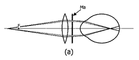
図1は、全ての既知の屈折計の原理であるScheinerの原理を示している。 FIG. 1 shows the Scheiner principle, which is the principle of all known refractometers.
焦点Fを有する外部レンズは、倍のピンホールを有するマスクMaの前に配置される。正しい調節の場合にのみ、双方のスポットは、((c)で示される)単一のより明るいスポットを構成するために網膜上でマージする。 The external lens having the focal point F is disposed in front of the mask Ma having double pinholes. Only with correct adjustment, both spots merge on the retina to form a single brighter spot (indicated by (c)).
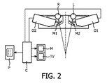
図2は、Okuyamaにより提案されたオプトメータを示している。 FIG. 2 shows the optometer proposed by Okuyama.
光二色性の鏡M1及びM2が、左側の目L及び右側の目Rの前に配置され、左側及び右側のオプトメータO1及びO2が用いられる。信号は、ペンレコーダP、モニタM及び/又はTVに結果を送り得る制御ユニットCに送られる。 Photodichroic mirrors M1 and M2 are arranged in front of the left eye L and the right eye R, and left and right optometers O1 and O2 are used. The signal is sent to a control unit C which can send the result to the pen recorder P, monitor M and / or TV.
明らかに、Okuyamaによる自動屈折レンズが自然な目標上に視野を与えるにも関わらず、目の近くの半透明の鏡による障害物及び顎当ての必要性は、自然な観察体験を作り出さない。 Obviously, the need for a translucent mirrored obstruction and chin rest near the eyes does not create a natural viewing experience, even though the auto-refractive lens by Okuyama gives a field of view on the natural target.
本発明は、目的として、大きな距離からのレンズベースの結像系の集光距離を遠隔で検出する可能性を提供しなければならない。 The present invention has as its object to provide the possibility to remotely detect the focusing distance of a lens-based imaging system from a large distance.
この目的を達成するために、本発明のシステムは、光の1又はそれ以上のパターンを投射するための光投射デバイスと、1又はそれ以上の既知の焦点面で1又はそれ以上のパターンを与えるための手段と、レンズの画像面上の1又はそれ以上の光パターンの反射の画像を測定するための投射デバイスの光学軸と少なくとも部分的に一致する光学軸を有するカメラと、1又はそれ以上の反射されたパターンのシャープネスを分析するための画像プロセッサとを有する。 To achieve this objective, the system of the present invention provides a light projection device for projecting one or more patterns of light and one or more patterns at one or more known focal planes. Means for, a camera having an optical axis at least partially coincident with the optical axis of the projection device for measuring an image of the reflection of one or more light patterns on the image plane of the lens, and one or more And an image processor for analyzing the sharpness of the reflected pattern.
本発明は、(人間の)目に役立つので、調節が生じる焦点距離を与え、それ故、アテンションの瞬間的なオブジェクトまでの距離を現す。 The present invention is useful for the (human) eye, so it gives the focal distance at which the adjustment occurs, and thus represents the instantaneous distance to the object of attention.
眼球調節を測定するための既存のシステムとは対照的に、本発明は、調節が観察経路における半透明の光学素子又は目の周辺における素子により視界を妨げることなく測定されるように、全体として控え目である。 In contrast to existing systems for measuring eye accommodation, the present invention as a whole is such that accommodation is measured without disturbing the field of view by translucent optical elements in the observation path or elements around the eye. Be humble.
眼球調節を測定するための既存のシステムとは対照的に、提案されたシステムは、典型的にはピコビーマー又はウェブカメラのサイズを有するより小さい形状因子によって構成され得る。 In contrast to existing systems for measuring eye accommodation, the proposed system can be constructed with a smaller form factor, typically having the size of a pico beamer or webcam.
光学素子の単純な構造及び適切な焦点の潜在的に単純な検出は、低コストな実装を可能にする。 The simple structure of the optical element and the potentially simple detection of the appropriate focus allows for a low cost implementation.
画像処理ユニットにより知られるパターンの使用は、焦点における特定のパターンが目によって同軸カメラのフレーム内の多かれ少なかれ同じ位置に常に送り返されるので、動作に対して本質的に強い焦点検出を行う。これは、同軸幾何学的形状に起因して単純である。これは、システムをモーションブラーに対して強くする。 The use of a pattern known by the image processing unit provides a focus detection that is inherently strong in motion, as a particular pattern at the focus is always sent back by the eye to more or less the same position in the frame of the coaxial camera. This is simple due to the coaxial geometry. This makes the system strong against motion blur.
また、実施形態において述べられるような複数のパターンの使用は、複数の人間の被験者の個々の眼球調節の同時検出を可能にすべきである。 Also, the use of multiple patterns as described in the embodiments should allow simultaneous detection of individual eye accommodations of multiple human subjects.
図3は、指向性反射の原理を示している。赤目効果(即ち、網膜反射)は、比較的凝視方向から独立している。被験者は、カメラ又は隣接するフラッシュの方向を見ている必要はない。光源は、明るい網膜投射を生成する。被験者はカメラ及びフラッシュに注目する傾向にあるので、光は網膜に効果的に集中し、網膜上の光源のスポットが目から光源まで外方に投射する二次的光源として機能することをもたらす。Fermatの原理に基づいて、光源の接合点及び網膜画像上の光源の画像は、光の方向に関わらず互いに収まり、従って、網膜上の光源の反射の画像及び光源は同じ点にある。結果として、目は自然な逆反射特性を有する。 FIG. 3 shows the principle of directional reflection. The red-eye effect (ie, retinal reflection) is relatively independent of the gaze direction. The subject need not be looking in the direction of the camera or the adjacent flash. The light source produces a bright retinal projection. Since the subject tends to focus on the camera and flash, the light is effectively concentrated on the retina, resulting in the spot of the light source on the retina acting as a secondary light source projecting outward from the eye to the light source. Based on Fermat's principle, the junction of the light source and the image of the light source on the retinal image fit together regardless of the direction of the light, so the image of the reflection of the light source on the retina and the light source are at the same point. As a result, the eye has natural retroreflective properties.
図4は、本発明のシステム及び方法を示す。 FIG. 4 illustrates the system and method of the present invention.
プロジェクタP及びカメラCAMは同じ光学軸を共有する、即ち、半透明の鏡であり得るビームスプリッタBSPの使用により、AXCAM及びAXPが一致する。プロジェクタは、パターンの点の収集が焦点面FPL1においてそのパターンのシャープな画像を形成するようにパターンP1の各点A1が点A2で投射されるようにパターンを投射する。プロジェクタ及びカメラは、それぞれレンズL1及びL2を備えている。 The projector P and the camera CAM share the same optical axis, i.e. AXCAM and AXP coincide by the use of a beam splitter BSP, which can be a translucent mirror. The projector projects the pattern so that each point A1 of the pattern P1 is projected at the point A2 so that the collection of pattern points forms a sharp image of the pattern on the focal plane FPL1. The projector and the camera are provided with lenses L1 and L2, respectively.
我々がプロジェクタの焦点面にスクリーンを配置する場合、カメラは投射A2を獲得することが可能であるだろう。これは、その焦点面がプロジェクタの焦点面と一致した場合にのみ、センサ上の単一の点A5として現れるだろう。しかしながら、スクリーンはない。物理的な投射スクリーン、遠隔結像系がない場合、この場合において、遠隔結像系(この場合においては目)の焦点面、即ち焦点面FPL2上に点A2がたまたまあるという条件下で、目EYEは、点A3における網膜上で点A2を集光し、点A4を介してその点を点A5上のカメラに送り返すだろう。図4において、遠隔の目は、空間B2における点にフォーカスされ、これは、それ故、目の瞬間的な焦点面FPL2に配置される(目の現実の焦点面が或る湾曲を有する焦点面であることに留意されたい)。これを行うのに、目の焦点面は、カメラ及びプロジェクタの焦点面FPL1と一致する。結果として、これは、目の網膜上にシャープな画像を形成している。3つの結像系の各々のフィールドの深度が、一致する焦点のエリアを2つの焦点面周辺の3Dボリュームに広げる傾向があるので、実際には、投射されたパターン全体は、焦点について送り返されるだろう。もちろん、2つの光学軸の間の角度がより大きくなるときに、一致する焦点ボリュームは減少する。 If we place the screen in the focal plane of the projector, the camera will be able to acquire projection A2. This will only appear as a single point A5 on the sensor if its focal plane coincides with the focal plane of the projector. However, there is no screen. In the absence of a physical projection screen, a remote imaging system, in this case, the eye is subject to the condition that the point A2 happens to be on the focal plane of the remote imaging system (in this case the eye), ie the focal plane FPL2. EYE will collect point A2 on the retina at point A3 and send it back to the camera on point A5 via point A4. In FIG. 4, the remote eye is focused on a point in space B2, which is therefore placed in the instantaneous focal plane FPL2 of the eye (the focal plane in which the real focal plane of the eye has a certain curvature). Note that). To do this, the focal plane of the eye coincides with the focal plane FPL1 of the camera and projector. As a result, this forms a sharp image on the retina of the eye. In practice, the entire projected pattern will be sent back in focus, as the depth of field of each of the three imaging systems tends to expand the area of matching focus to a 3D volume around the two focal planes. Let's go. Of course, as the angle between the two optical axes becomes larger, the matching focal volume decreases.
焦点検出は、投射されたパターン又は(向きのような)投射されたパターンの少なくとも一態様が画像処理ユニットにより知られているという事実に基づいている。予め決められた面で焦点の発生を検出するために、遠隔結像系(目)は、その断片だけが同じ距離にある物理的なスクリーン上に投射される場合に、そのパターンの断片をカメラに送り返すだろう。簡単に言うと、目の焦点面並びにプロジェクタ及びカメラの焦点面が一致する場合にのみ、カメラが網膜上のパターンのシャープな逆反射を記録するだろう。図4は、目EYEと目の焦点面FPL2との間に何もないことを示している。眼球調節測定は、遠くから行われる。調査中の人は、測定デバイスを見る必要もないか又は目の前に配置される半透明の鏡を有する必要もないし、顎当てを用いる必要もない。本方法は、全体として控え目であり、赤外線が用いられた場合には、人が観察に気づくことなく用いられ得る。それにもかかわらず観察者に対して知覚されないか又は少なくとも気を散らさない可視光を用いる例が以下で与えられる。この例では、目は点B1において集光している。B1の画像は網膜上の点B2にあり、網膜は、離れた光学結像系のセンサ表面であり、人間の目である。 Focus detection is based on the fact that at least one aspect of the projected pattern or projected pattern (such as orientation) is known by the image processing unit. In order to detect the occurrence of a focal point at a predetermined plane, the remote imaging system (eye) can capture a fragment of the pattern when only that fragment is projected onto a physical screen at the same distance. Would send it back to. Simply put, the camera will record a sharp retroreflection of the pattern on the retina only if the focal planes of the eyes and the focal planes of the projector and camera match. FIG. 4 shows that there is nothing between the eye EYE and the focal plane FPL2 of the eye. The eye accommodation measurement is performed from a distance. The person under investigation does not need to see the measuring device or have a translucent mirror placed in front of the eyes, nor does it need to use a chin rest. This method is modest as a whole and can be used without human being aware of the observation when infrared is used. An example is given below using visible light that is nevertheless perceived by the viewer or at least not distracting. In this example, the eyes are focused at point B1. The image of B1 is at point B2 on the retina, which is the sensor surface of the remote optical imaging system and the human eye.
共通焦点面に基づく焦点検出の新たな原理は、焦点距離の予め決められた範囲内の焦点推定、焦点測定又は焦点追跡のために用いられ得る。焦点の検出を基礎として用いた場合、焦点距離の範囲からの焦点の推定又は測定のための種々の方法がある。 The new principle of focus detection based on a common focal plane can be used for focus estimation, focus measurement or focus tracking within a predetermined range of focal lengths. When used as a basis for focus detection, there are various methods for focus estimation or measurement from a range of focal lengths.
単一の投射された発光パターンを用いた場合、本発明の一実施形態は、プロジェクタ及びカメラの共通焦点距離の組み合わせられた調整に基づく。新たな焦点検出原理を用いた場合、プロジェクタ及びカメラの共通焦点面は、投射パターンが目から最適に検出されるまで調整される。すなわち、網膜上のパターンの反射が最も鋭い。共通焦点距離のそのように見つけられた値は、目の焦点距離を示す。複数のパターンの投射を用いた場合、本発明の種々の実施形態は、全て、各々が他の距離でフォーカスされる複数のパターンの投射に基づいて、以下で与えられる。パターンがカメラのフィールドの深度の範囲内にある限り、特定のパターンの検出は関連した距離での焦点を示す。 With a single projected emission pattern, one embodiment of the present invention is based on a combined adjustment of the common focal length of the projector and camera. When the new focus detection principle is used, the common focal plane of the projector and camera is adjusted until the projection pattern is optimally detected from the eye. That is, the reflection of the pattern on the retina is the sharpest. The so-found value of the common focal length indicates the focal length of the eye. When using multiple pattern projections, various embodiments of the present invention are all given below based on multiple pattern projections, each focused at another distance. As long as the pattern is within the depth of the camera field, the detection of a particular pattern will show focus at the relevant distance.
カメラCAMは、画像センサISを有する。画像センサISの信号は、画像のシャープネスを測定するために、画像処理ユニットIPに送られる。 The camera CAM has an image sensor IS. The signal of the image sensor IS is sent to the image processing unit IP in order to measure the sharpness of the image.
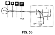
図5A、5Bおよび5Cは、本発明によるデバイスのための考えられるセットアップを示している。 Figures 5A, 5B and 5C show possible setups for a device according to the invention.
図5Aにおいて、プロジェクタ及びカメラはそれぞれ別個のレンズを有し、図5Bにおいて、プロジェクタ及びカメラは共通レンズを共有する。これは、システムの素子の数を低減する。図5Cにおいて、カメラ及びプロジェクタの位置は、図5Bと比較して入れ替えられている。これは、好ましい実施形態である。カメラがビームスプリッタを介して真っ直ぐに見ることが好ましい。もちろん、図5Aにおいて、カメラ及びプロジェクタが入れ替えられてもよい。 In FIG. 5A, the projector and the camera each have a separate lens, and in FIG. 5B, the projector and the camera share a common lens. This reduces the number of elements in the system. In FIG. 5C, the positions of the camera and the projector are switched compared to FIG. 5B. This is the preferred embodiment. Preferably, the camera looks straight through the beam splitter. Of course, in FIG. 5A, the camera and the projector may be interchanged.
また、図5A〜5Cは、目の網膜で反射されたパターンのカメラにより撮られた画像を示している。目の焦点面FLP2がプロジェクタ及びカメラの焦点面と一致したときに、比較的シャープな画像が見られ、この画像は、目の焦点面がプロジェクタ及びカメラの焦点面と異なるにつれて次第にぼかされる。観察された画像は、(目によって図面に示された)外部の結像系の定常状態焦点の間に焦点を変えているときに、同軸カメラにより撮られる。或る範囲に渡ってプロジェクタ及びカメラの焦点面をスウィープして同時に画像を記録すること、画像処理を用いること、画像のシャープネスを決定することは、プロジェクタ及びカメラのための特定の焦点面で最大のシャープネスを与える。目の焦点面は、そのように見つけられた焦点面に対応する。 5A to 5C show images taken by the camera having a pattern reflected by the retina of the eye. A relatively sharp image is seen when the focal plane FLP2 of the eye coincides with the focal plane of the projector and camera, and this image is gradually blurred as the focal plane of the eye differs from the focal plane of the projector and camera. The observed image is taken by a coaxial camera when changing focus during the steady state focus of the external imaging system (shown in the drawing by the eye). Sweeping the focal plane of the projector and camera over a range and simultaneously recording an image, using image processing, and determining image sharpness are the largest at a specific focal plane for the projector and camera. Give the sharpness. The focal plane of the eye corresponds to the focal plane so found.
パターンは、赤外線の(IR)光において与えられてもよい。 The pattern may be provided in infrared (IR) light.
パターンは、好ましい実施形態において、カメラが背景画像と発光パターンの投射を有する画像とを交互に取得するように、それぞれ交互のビデオフレームにおいて与えられてもよい。背景画像の差し引きは、網膜上に発光パターンの反射だけを残し、これにより、パターンの反射の検出可能性を大幅に強化する。 The pattern may be provided in alternating video frames so that, in a preferred embodiment, the camera alternately acquires a background image and an image with a projection of the light emission pattern. The subtraction of the background image leaves only the reflection of the luminescent pattern on the retina, thereby greatly enhancing the detectability of the pattern reflection.
パターンは、好ましい実施形態において、時間的周波数(例えば、70Hz)を与えられてもよい。好ましくは、周波数は、例えば可視又は赤外線の光の他の供給源で用いられた周波数には対応しない。そして、カメラは、プロジェクタの周波数周辺の周波数の範囲内にないIR信号をフィルタリングするために周波数フィルタを用いることにより、その周波数に調整されてもよい。斯様な好ましい実施形態において、背景信号がフィルタリングされる。 The pattern may be given a temporal frequency (eg, 70 Hz) in a preferred embodiment. Preferably, the frequency does not correspond to the frequency used in other sources of, for example, visible or infrared light. The camera may then be adjusted to that frequency by using a frequency filter to filter IR signals that are not in the frequency range around the projector frequency. In such a preferred embodiment, the background signal is filtered.
図6は、パターンが或る範囲に渡ってスウィープされたときの(カメラの画像センサ上で獲得される)網膜上のパターンの反射を示している。 FIG. 6 shows the reflection of the pattern on the retina (obtained on the camera's image sensor) when the pattern is swept over a range.
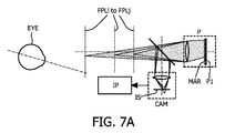
図7A〜7Cは、本発明のシステム及び方法の一実施形態を示している。この実施形態と先の実施形態との間の差は、複数の焦点面FPLi〜FPLjがマイクロレンズアレイを用いて作られる点である。これらの実施形態のシステムは、それぞれが異なる距離で集光した異なるパターンを含む光フィールドを生成するためにプロジェクタの経路内に配置されたマイクロレンズアレイMARを有する。この技術を用いた場合、別々に集光されたパターンのスタック、又は、既知の態様が距離の関数として変化するこれらの連続パターンを生成することが可能である。斯様なパターンは格子パターンであり得る。そして、パターンの向きは、パターンの既知の態様として用いられ得る。カメラ上の画像を解析することにより、これは、目の焦点面を見つけることができる。また、異なる距離での同時投射は、システムの範囲内において複数の被験者の中の個々の眼球調節の推定を可能にする。これは、既知のシステムでは不可能である。図7Aにおいて、マイクロレンズアレイが、プロジェクタ光経路内に配置され、類似の効果が、カメラの光経路内にマイクロレンズアレイを配置することにより得られ、この場合において、plenopticプロジェクタの代わりにplenopticカメラが用いられる。この構成は図7Cにおいて概略的に示されている。好ましい実施形態において、マイクロレンズアレイは、図7Bにおいて概略的に示されるように、カメラ及びプロジェクタの双方の前に配置される。後者の構成は、プロジェクタの画素とカメラの画素との間に1:1の関係を与え、これは有利である。 7A-7C illustrate one embodiment of the system and method of the present invention. The difference between this embodiment and the previous embodiment is that a plurality of focal planes FPLi to FPLj are made using a microlens array. The systems of these embodiments have a microlens array MAR placed in the projector path to produce a light field that includes different patterns, each collected at a different distance. Using this technique, it is possible to generate a stack of separately focused patterns or these continuous patterns whose known aspects vary as a function of distance. Such a pattern can be a lattice pattern. The pattern orientation can then be used as a known aspect of the pattern. By analyzing the image on the camera, this can find the focal plane of the eye. Also, simultaneous projection at different distances allows estimation of individual eye accommodation among multiple subjects within the system. This is not possible with known systems. In FIG. 7A, a microlens array is placed in the projector light path and a similar effect is obtained by placing the microlens array in the camera light path, in which case a plenoptic camera instead of a plenoptic projector. Is used. This configuration is shown schematically in FIG. 7C. In a preferred embodiment, the microlens array is placed in front of both the camera and projector, as shown schematically in FIG. 7B. The latter configuration provides a 1: 1 relationship between projector pixels and camera pixels, which is advantageous.
マイクロレンズアレイの代わりに、プロジェクタは、それぞれが異なるパターンを有する、プロジェクタレンズ後方に異なる距離で異なるスライドのスタックを含み得る。 Instead of a microlens array, the projector may include a stack of different slides at different distances behind the projector lens, each having a different pattern.
パターンマスクは、異なる距離で異なる特性を有する光フィールドを生成する回折要素であってもよい。ホログラムがこの目的のために用いられてもよい。 The pattern mask may be a diffractive element that produces optical fields having different characteristics at different distances. A hologram may be used for this purpose.
複数の距離でのパターン(又は複数のパターン)の生成は、時間経時的な方法で実行されてもよく、カメラが同期化されたイメージキャプチャを用いることが提供される。 Generation of patterns (or patterns) at multiple distances may be performed in a time-dependent manner, providing that the camera uses synchronized image capture.
また、互いに同一線上に複数のプロジェクタの光学軸をもたらすために鏡を用いて、異なる距離で静的なパターンを投射する1よりも多いプロジェクタを用いることも可能である。 It is also possible to use more than one projector that projects a static pattern at different distances using a mirror to provide the optical axes of multiple projectors on the same line.
適切なパターンが与えられた場合、パターンのブラーは、その投射が焦点外にある方向をすぐに識別することができる。これは、伝達されたパターンを焦点内に維持するようにプロジェクタ(及びカメラ)の焦点を機械的に制御するために用いられ得る。そして、制御システムは、未知のシステム(即ち、目の焦点面)の焦点距離を自動的に示す。欠点は、同時の複数のパターン投射の使用とは対照的に、これが、単一の未知のカメラ又は単一の被験者に対して調整され得ることである。目の調節を追跡するためのシステム及び方法がここで述べられ、目及びシステムと同様の態様のカメラ機能がカメラの焦点を追跡するために用いられてもよいことが述べられる。 Given an appropriate pattern, pattern blur can quickly identify the direction in which the projection is out of focus. This can be used to mechanically control the focus of the projector (and camera) to keep the transmitted pattern in focus. The control system then automatically indicates the focal length of the unknown system (ie, the focal plane of the eye). The disadvantage is that it can be adjusted for a single unknown camera or a single subject as opposed to using multiple pattern projections simultaneously. Systems and methods for tracking eye accommodation are described herein, and it is stated that camera functions in a manner similar to eyes and systems may be used to track camera focus.
また、システムは、目が無限距離で集光している時を検出可能である。プロジェクタの焦点面と目の焦点面とが斯様な状況において一致し得ないとしても、それにもかかわらず、カメラのセンサ上にパターンは、目が無限距離で集光しているときに、はっきりと撮像されるだろう。図8は、斯様な状況を示している。プロジェクタにより放射された平行光線は、目により集光され、無限距離上に、網膜に、集光しているとき、及び、網膜から反射された光線が平行光線を形成したときに、これらは、カメラのセンサ上に集光される。それ故、システムは、目が無限距離上に集光しているかどうかを確立することが可能である。 The system can also detect when the eyes are concentrating at an infinite distance. Even though the focal plane of the projector and the focal plane of the eye cannot coincide in such a situation, the pattern on the camera sensor is nevertheless clear when the eye is focused at an infinite distance. Will be imaged. FIG. 8 shows such a situation. When collimated light rays emitted by the projector are collected by the eye and focused on the retina over an infinite distance, and when the light rays reflected from the retina form parallel rays, these are: Focused on the camera sensor. Therefore, the system can establish whether the eye is focused over an infinite distance.
複数のパターンが種々の焦点面で形成される状況において、1つのパターンが無限距離に確保されてもよい。シャープネスの測定のための方法は知られている。1つのシャープネスを測定する手段は、例えば、パターン内の線の範囲、及び/又は、反射されたパターン内の最大と最小との間の割合を測定することである。パターン内の線の範囲は、パターンがフォーカスされたときの(即ちシャープ)、最大と最小との間の割合を示すだろう。 In a situation where a plurality of patterns are formed with various focal planes, one pattern may be secured at an infinite distance. Methods for measuring sharpness are known. One means of measuring sharpness is, for example, measuring the range of lines in the pattern and / or the ratio between the maximum and minimum in the reflected pattern. The range of lines in the pattern will indicate the ratio between the maximum and minimum when the pattern is focused (ie sharp).
更に、上述したように、2つの光学軸間、即ち、目の光学軸とプロジェクタ及びカメラの光学軸との間の角度がより大きくなったときに、一致する焦点のボリュームは減少する。我々は、プロジェクタの、及び、必要に応じて、カメラの焦点面を回転させることにより、この回転を補正することができる。図9は、プロジェクタの焦点面の回転を示している。これは、Theodor Scheimpflugにより最初に提案されたScheimpflugの構成として知られた(例えば、GB patent no. 1196, May 1904参照)、レンズ面に対する画像面の回転により実現される。その発明者の名をとって名づけられた、この傾けられたレンズの幾何学的形状は、焦点面がレンズ面に対する回転を得ることをもたらす。拡張された焦点面は、拡張された画像面及び拡張されたレンズ面と同一ラインで交差するだろう。代わりに、これは、観察されるべき目を観て種々の反射されたパターンを解析するプロジェクタ及びカメラの幾つかの対を用いることができる。 Furthermore, as described above, the volume of the matching focus decreases as the angle between the two optical axes, ie, the optical axis of the eye and the optical axis of the projector and camera, increases. We can correct this rotation by rotating the focal plane of the projector and, if necessary, the camera. FIG. 9 shows the rotation of the focal plane of the projector. This is known as the Scheimpflug configuration originally proposed by Theodor Scheimpflug (see, for example, GB patent no. 1196, May 1904) and is achieved by rotation of the image plane relative to the lens surface. This tilted lens geometry, named after the inventor, results in the focal plane gaining rotation relative to the lens surface. The extended focal plane will intersect the extended image plane and the extended lens plane in the same line. Instead, it can use several projector and camera pairs that look at the eye to be observed and analyze the various reflected patterns.
図10の本発明の方法の例において、プロジェクタは、カメラCam1、Cam2などのアレイにより囲まれている(この例においてはプロジェクタ)。カメラのエリアを用いた場合、これは、アレイの中心に光フィールドを確立することができる。カメラのアレイにより与えられた画像を用いた場合、フィールドの種々の深度の画像が復元され得る。これは、カメラのアレイにより撮られた画像から深度情報が得られるのを可能にする。この方法の利点は、深度情報が予め知られている必要がないことである。目の位置は、カメラのアレイの画像を解析することにより得られ得る。 In the example of the method of the present invention in FIG. 10, the projector is surrounded by an array of cameras Cam1, Cam2, etc. (in this example, a projector). With the camera area, this can establish a light field in the center of the array. When using images provided by an array of cameras, images of various depths of the field can be restored. This allows depth information to be obtained from images taken by an array of cameras. The advantage of this method is that the depth information need not be known in advance. The eye position can be obtained by analyzing an image of an array of cameras.
全ての実施形態におけるシステム及び方法は、バイタルサインを追跡するために用いられ得る。 The systems and methods in all embodiments can be used to track vital signs.
人間が固定された距離にフォーカスし続けたときに、この定常の眼球調節は、周期的呼吸及び鼓動によって変化することが知られている。そのようなものとして、調節の検出がこれらのバイタルサインを与えてもよい。本発明のシステムが、控え目な態様で及び或る距離からこれを行うことができるという事実は、未だ可能ではない可能性を提供する。例えば、耐久性テストを受けている人の心拍数及び周期的呼吸が測定されるべきときには、これは、ワイヤで人のじゃまをする必要なく行われ得る。 It is known that this steady eye accommodation changes with periodic breathing and beating when a human continues to focus on a fixed distance. As such, the detection of regulation may give these vital signs. The fact that the system of the present invention can do this in a conservative manner and from a certain distance offers the possibility not yet possible. For example, when the heart rate and periodic breathing of a person undergoing an endurance test are to be measured, this can be done without having to disturb the person with a wire.
一方で、外部的に測定されたバイタル信号が与えられた場合、眼球調節の測定は、これらが集光距離上でもたらす調整のために原理上修正され得る。 On the other hand, given externally measured vital signals, the measurements of eye accommodation can be modified in principle for the adjustments they make on the collection distance.
使用されるカメラは、光フィールドカメラ、即ち、フィールド深度の或る範囲で焦点が合っている画像を作るために用いられ得る画像データを与えることが可能なカメラであってもよい。従来のカメラを合成開口により光フィールドカメラに変換するための種々の方法がある。光フィールドカメラの利点は、単一の露光において、光線の完全なフィールドを一体的に獲得することであり、ここから、単一の獲得されたフレームに基づき焦点又は焦点範囲を逆向きに調整することが可能である。そのようなものとして、獲得された光フィールドは、遠隔の目の焦点距離の推定又は測定をすぐに与える。斯様なカメラは、コード化された開口又はレンズとセンサとの間の光学経路内の変化するパターンの使用により(まだらのフォトグラフィ)、センサの前のマイクロレンズアレイを用いて構成され得る。 The camera used may be a light field camera, i.e. a camera capable of providing image data that can be used to produce an image that is in focus over a range of field depth. There are various ways to convert a conventional camera into an optical field camera with a synthetic aperture. The advantage of a light field camera is that it captures a complete field of rays together in a single exposure, from which the focus or range of focus is adjusted backwards based on a single acquired frame. It is possible. As such, the acquired light field immediately provides an estimate or measurement of the remote eye focal length. Such a camera can be configured with a microlens array in front of the sensor by using a coded aperture or a changing pattern in the optical path between the lens and the sensor (mottle photography).
種々の方法が、露光を犠牲にすることなくカメラのフィールドの深度を拡張するために存在する。これらの方法は、カメラが特定のパターンの検出のために用いられ、定期的な画像キャプチャの獲得のために用いられない時に特に興味深い。既知の方法は、焦点スウィープイメージングの使用である。 Various methods exist to extend the depth of the camera field without sacrificing exposure. These methods are particularly interesting when the camera is used for detection of specific patterns and not for acquisition of regular image captures. A known method is the use of focus sweep imaging.
本発明の実施形態において、焦点検出は、凝視検出と組み合わせて用いられる。 In an embodiment of the invention, focus detection is used in combination with gaze detection.
凝視検出及び焦点検出を組み合わせることにより、デバイスの方向において意図的に凝視することから誤って凝視することの曖昧さをなくすことが可能となる。この場合において、システムは、場合によりボタンからの又は口語的なコマンドの解釈から来る他のトリガと組み合わせて、凝視に基づき制御されるべき特定のデバイスの部分である。 Combining gaze detection and focus detection makes it possible to eliminate the ambiguity of erroneous gaze from intentional gaze in the direction of the device. In this case, the system is part of a particular device that is to be controlled based on staring, possibly in combination with other triggers that come from buttons or from colloquial command interpretation.
とりわけデバイス自体に配置されるべき投射された焦点面を選択することにより、凝視に加えて意図的な焦点を検出することが可能となる。適切な焦点を検出することなく凝視を検出した場合には、誤って凝視しているとみなされ、デバイスの制御を開始するためのトリガとして無視され得る。 In particular, by selecting the projected focal plane to be placed on the device itself, it is possible to detect intentional focus in addition to staring. If a gaze is detected without detecting the proper focus, it is considered to be staring in error and can be ignored as a trigger to initiate control of the device.
凝視検出がカメラ及び同軸(赤外線)照射の使用に既に基づいているので、凝視検出及び焦点検出は、少ない追加のコストで効率的に一体化され得る。 Since gaze detection is already based on the use of a camera and coaxial (infrared) illumination, gaze detection and focus detection can be efficiently integrated with little additional cost.
凝視推定と組み合わせた焦点検出又は推定の使用。 Use of focus detection or estimation combined with gaze estimation.
凝視推定の組み合わせは、3D空間中の点の凝視の検出を可能にする。3Dディスプレイ(ホログラフィック)との組み合わせは、固有の機能を可能にしてもよい。 The combination of gaze estimation allows for the detection of point gaze in 3D space. The combination with a 3D display (holographic) may allow unique functions.
本発明のシステム及び方法は、幾つかのアプリケーションのために又はこれらにおいて用いられてもよい。 The system and method of the present invention may be used for or in some applications.
人間における眼球調節の遠隔推定は、場合により凝視検出と組み合わせて、電子看板の状況で視覚的注意力を測定するために、注意力を検知するために用いられ得る。集光距離に関する認識は、"見る"及び"凝視"の曖昧さをなくすために役に立ち得る。 Remote estimation of eye accommodation in humans can be used to detect attention in order to measure visual attention in the context of a digital signage, possibly in combination with gaze detection. The perception of the focusing distance can help to disambiguate “see” and “gaze”.
また、場合により凝視検出と組み合わせて、これは、見られたときに口語的なコマンド又はジェスチャにのみ応答する注意深いユーザインタフェースとして用いられ得る。 Also, optionally in combination with gaze detection, this can be used as a careful user interface that responds only to spoken commands or gestures when viewed.
また、眼球調節の遠隔測定は、視覚系の適切な成長をモニタするために子供における視覚的欠陥の検出において用いられることができる。 Telemetry of eye accommodation can also be used in the detection of visual defects in children to monitor the proper growth of the visual system.
無限距離での調節の検出は、ドライバが路上で充分な焦点を呈するかどうかを明らかにすることができる。 The detection of accommodation at infinite distance can reveal whether the driver has sufficient focus on the road.
身体の不自由な人のための凝視制御ユーザインタフェースの部分として、例えばマウス制御において、ロバスト性を提供してもよい。 As part of a gaze control user interface for a physically handicapped person, robustness may be provided, for example, in mouse control.
光学系と組み合わせた場合、光学系を目の屈折状態に自動的に適応させるための手段を提供してもよい。本方法が控え目に機能するとともにより小さい形状因子を可能にするので、本アプリケーションは、従来の眼科学の範囲を越えてもよく、消費者向け市場のための光学製品の部分であってもよい。 When combined with an optical system, means may be provided for automatically adapting the optical system to the refractive state of the eye. Because the method works sparingly and allows for smaller form factors, the application may go beyond the traditional ophthalmology and may be part of an optical product for the consumer market. .
セキュリティシステムにおいて、人間の視覚的焦点の検出は、不所望な注意力を検出するために用いられてもよい。不所望なカメラ焦点の検出が検出されてもよい。述べられたように、システムは、カメラの焦点距離を測定するために用いられてもよい。 In security systems, human visual focus detection may be used to detect unwanted attention. Undesirable camera focus detection may be detected. As stated, the system may be used to measure the focal length of the camera.
控え目な性質は、本原理をとりわけ非協力的な被験者(例えば、幼児、(野生の)動物)を伴うアプリケーションに適合させる。 The discreet nature makes this principle especially suitable for applications involving non-cooperating subjects (eg infants, (wild) animals).
また、本発明は、如何なる実施形態においても、プログラムがコンピュータ上で実行されたときに、本発明の方法を実行するためのプログラムコード手段を有するコンピュータプログラムに関する。また、本発明は、本発明の方法を実行するためにコンピュータ読み取り可能な媒体に格納されたプログラムコード手段を有するコンピュータプログラムプロダクトに関する。 The present invention also relates to a computer program having program code means for executing the method of the present invention when the program is executed on the computer in any embodiment. The invention also relates to a computer program product comprising program code means stored on a computer readable medium for performing the method of the invention.
カメラは、画像を記録するための任意のデバイスである。 A camera is any device for recording images.
また、これは、通信のような他の目的のために用いられるデバイスの一部であってもよく、斯様な通信デバイスに取り付けられるか、斯様な通信デバイスに一体化されるか又は斯様な通信デバイスにと協働してもよい。 It may also be part of a device used for other purposes such as communication, attached to such communication device, integrated into such communication device or such May cooperate with various communication devices.
更に他の実施形態は、異なる波長の発光パターンの使用にある(例えば、可視範囲のいずれかの端及び可視範囲の中心部分での、3つの異なる波長(例えば赤/緑/青))。3つの波長で焦点距離を測定することは、目の収差に関する情報を与える。各波長に対して焦点距離が測定され、これは同時に行われ得る。これは、眼球調節の瞬時及び遠隔測定だけでなく、3つの異なる波長(即ち、収差)における眼球調節のための瞬時及び遠隔測定を与える。 Yet another embodiment is the use of emission patterns of different wavelengths (eg, three different wavelengths (eg, red / green / blue) at either end of the visible range and the central portion of the visible range). Measuring the focal length at three wavelengths gives information about the aberrations of the eye. The focal length is measured for each wavelength and this can be done simultaneously. This provides not only instantaneous and telemetry of eye accommodation, but also instantaneous and telemetry for eye accommodation at three different wavelengths (ie aberrations).
また、隠された発光パターン(即ち、人間の目ではほとんど見えないパターン)が使用されてもよい。1つの手段は、発光パターンのために赤外線を用いることである。 Also, a hidden light emission pattern (that is, a pattern that is hardly visible to the human eye) may be used. One means is to use infrared light for the light emission pattern.
他の手段は、人間の目が見ることができない態様において、投射された画像に目をそらさせないためにパターンを埋め込むことである。 Another means is to embed a pattern in a manner that the human eye cannot see to keep the projected image from looking away.
プロジェクタは、単純な白色光エリアプラス1つのフレームにおけるパターン及び白色光エリアマイナス次のフレームにおける前記パターンを投射することができる。 The projector can project a simple white light area plus a pattern in one frame and a white light area minus the pattern in the next frame.
一のフレームにおいて、プロジェクタは、(最大の強度より小さい)白色光プラスパターンを投射し、次のフレームにおいて、プロジェクタは、白色光マイナス前記パターンを投射する。フレーム周波数が人間の目に対して知覚可能な周波数を越えた場合には、人間の目は、前記パターンを知覚しないが、単なる白色光ランプを知覚するだろう。人間は、観察者により見られた単純な白色エリアだけを残す2つの投射間の差を平均するためである。白色光ランプは、観察者の注意力を引かない。それ故、測定を妨害しない。しかしながら、2つのフレームのためのカメラにより撮られた2つの画像を減算することにより、埋め込まれた発光パターンの反射は、カメラにより記録された画像において知覚可能である。プロジェクタにおける(人間の目に対して)隠されたパターンは、異なる色に対して異なってもよく、これは、パターンをより隠すために用いられてもよい。シーケンスは、例えば以下の通りであり得る。
I.(異なる構造パターンにおける)白色マイナス青色パターンプラス緑色パターン
II.白色マイナス緑色パターンプラス赤色パターン
III.白色プラス青色パターンマイナス赤色パターン
In one frame, the projector projects a white light plus pattern (less than the maximum intensity) and in the next frame the projector projects white light minus the pattern. If the frame frequency exceeds a frequency that is perceptible to the human eye, the human eye will not perceive the pattern but will perceive a simple white light lamp. This is because the human averages the difference between the two projections leaving only the simple white area seen by the viewer. The white light lamp does not attract the viewer's attention. Therefore, it does not interfere with the measurement. However, by subtracting the two images taken by the camera for the two frames, the reflection of the embedded light emission pattern is perceptible in the image recorded by the camera. The hidden pattern (for the human eye) in the projector may be different for different colors, and this may be used to make the pattern more concealed. The sequence can be, for example:
I. White minus blue pattern plus green pattern (in different structural patterns) II. White minus green pattern plus red pattern III. White plus blue pattern minus red pattern
パターン自体は、同じである必要はなく、異なっていてもよい。 The patterns themselves need not be the same and may be different.
目は、フレーム周波数がおおよそ50Hzを超えた場合、白色ランプを知覚するだろう。しかしながら、カメラは、IからのIIを減算し、"緑色のシグナル"を撮ることにより、緑色パターンの反射を抽出することができる。同様に、青色及び赤色パターンの、フレームの適切な減算により、反射を抽出することができる。 The eye will perceive a white lamp if the frame frequency exceeds approximately 50 Hz. However, the camera can extract the reflection of the green pattern by subtracting II from I and taking a “green signal”. Similarly, reflections can be extracted by appropriate subtraction of the blue and red pattern frames.
不可視パターンを作る他の手段は、例えば2つの色(例えばA−B)の千鳥格子パターンを用いることによる、人間にとって白色である合計である。一のフレームにおいて、千鳥格子パターンは、A−Bであり、次のフレームにおいて、B−Aである。この場合も同様に、人間の目は、パターンを示さない白色光を知覚するが、カメラは、フレームの適切な減算又は測定により、A及びBパターンの反射を抽出することができる。 Another means of creating an invisible pattern is a sum that is white for humans, for example by using a houndstooth pattern of two colors (eg AB). In one frame, the houndstooth pattern is AB, and in the next frame is B-A. Again, the human eye perceives white light that does not show a pattern, but the camera can extract the reflections of the A and B patterns by appropriate subtraction or measurement of the frame.
更に他の手段は、3又はそれ以上の異なって着色された部分(例えば、色A−B−Cを有するハニカムパターン)を有するパターンを用いることである。より多くのフレームの3つの反復するサイクルを用いることにより(A−B−C;C−A−B;A−B−C等)、人間の目が白色光を見る全ての部分でのサイクルに渡る平均として、任意の下にあるパターンが人間の目に対して不可視である。 Yet another means is to use a pattern having three or more differently colored portions (e.g., a honeycomb pattern having the colors ABC). By using three repeating cycles of more frames (ABC, CAB, ABC, etc.), the cycle in all parts where the human eye sees white light As an average across, any underlying pattern is invisible to the human eye.
しかしながら、記録カメラの信号は、3又はそれ以上の色の反射されたパターンに関する情報を抽出するために分析され得る。色の数は、収差に関するより詳細な情報を抽出するために、4又はそれ以上まで拡張され得る。 However, the recording camera signal can be analyzed to extract information about the reflected pattern of three or more colors. The number of colors can be extended to 4 or more to extract more detailed information about the aberrations.
方法は、例えば種々の手段における人間の目の動作に関する情報を与えるために用いられ得る。例えば、目が観察者の視野のフィールドの範囲内で移動するオブジェクトを追跡する観察者の目又は2つの目の反応を測定することにより、目又は目が集光し得る距離の範囲に関する情報を得ることが可能である。 The method can be used, for example, to provide information regarding the movement of the human eye in various ways. For example, information about the range of distance an eye or eye can collect by measuring the response of the observer's eye or two eyes tracking an object that moves within the field of view of the observer's field of view. It is possible to obtain.
ほとんどの状況において、これは、この情報に関して人に単純に尋ねることができる。しかしながら、これが可能ではない状況も存在する。人は、単純に、物理的又は精神的健康の理由のため通常の手順において要求されたテストを受けることができない、及び/又は、人は、伝達することができないためである。目のパラメータのための適切な推定を単純に与えることでさえ、大きな利点をもたらすだろう。任意のテストに関して良好な結果を得るための時間及び努力(及びそれ故に患者がテストを受けなければならない時間)は、とりわけ、テストの出発点により決定される。それ故、控え目な態様におけるより正確な測定に対して良好な出発点を与えることは、患者に大きな利益を与えることができる。 In most situations, this can simply be asked to the person for this information. However, there are situations where this is not possible. A person simply cannot receive the required tests in normal procedures for reasons of physical or mental health and / or cannot communicate. Even simply giving an appropriate estimate for the eye parameters would bring great benefits. The time and effort to obtain good results for any test (and hence the time that the patient has to take the test) is determined, among other things, by the starting point of the test. Therefore, providing a good starting point for more accurate measurements in a conservative manner can greatly benefit the patient.
双方の目の測定により、目の間の差分が検出及び測定され、これは、anisometryの量の指標を与えることができる。本発明は、例えば、子供が例えば玩具で遊んでいるか又は移動オブジェクトを見ている間に目の間の差分を検出することにより早い年齢で弱視の指標を与えるために用いることができる。 By measuring both eyes, the difference between the eyes is detected and measured, which can give an indication of the amount of anisometry. The present invention can be used, for example, to provide an indicator of amblyopia at an early age by detecting a difference between eyes while a child is playing with a toy or watching a moving object, for example.
方法におけるステップを実行するための手段は、ハードウェア、ソフトウェア又はその任意の組み合わせの形式であり得る。本発明の種々の実施形態によるシステム及びデバイスにおいて、方法のステップを実行するための手段が与えられる。説明又は請求項において、"ための手段"は、方法ステップのうちの1つを超えるものに従って述べられ、手段は、ステップの全てを実行するための組み合わせられた手段、多数の手段のための略語、又は、方法のステップの1又はそれ以上を実行するための手段のそれぞれである。従って、"生成するための手段"は、生成するための発生器と呼ばれ得る。種々の手段は、説明の容易さのために別個のものとして述べられた。これは、本発明が別個のユニットである斯様な手段に限定されることを意味するものではなく、機能は、一体化されたデバイス又はソフトウェアの部分において組み合わせられ得る。 The means for performing the steps in the method may be in the form of hardware, software or any combination thereof. Means are provided for performing method steps in systems and devices according to various embodiments of the invention. In the description or claims, "means for" is described according to more than one of the method steps, means being a combined means for performing all of the steps, abbreviations for multiple means. Or each of the means for performing one or more of the method steps. Thus, "means for generating" can be referred to as a generator for generating. Various means have been described as separate for ease of explanation. This does not mean that the invention is limited to such means being a separate unit, the functions can be combined in an integrated device or software part.
要するに、本発明は以下のように要約され得る:システム及び方法は、離れた光学結像系の光学焦点を測定する(とりわけ離れた被験者の眼球調節)。光の発光パターンが、離れた光学結像系の前にある既知の焦点面の焦点において投射され、離れた光学結像系、例えば目の網膜のセンサ表面上のパターンの反射の画像が、投射デバイスの光学軸と少なくとも部分的に一致するか又は該光学軸の近くにある光学軸を有するカメラにより記録される。センサ表面上で反射された発光パターンのシャープネスが決定される。 In summary, the present invention can be summarized as follows: The system and method measure the optical focus of a remote optical imaging system (especially the eye adjustment of a remote subject). A light emission pattern is projected at the focal point of a known focal plane in front of the remote optical imaging system, and an image of the reflection of the pattern on the sensor surface of the remote optical imaging system, for example the retina of the eye, is projected. Recorded by a camera having an optical axis that is at least partially coincident with or near the optical axis of the device. The sharpness of the light emission pattern reflected on the sensor surface is determined.
Claims (18)
光の発光パターンが前記離れた光学結像系の前記レンズの前にある既知の焦点面で焦点が合うように前記発光パターンを投射するための光投射デバイスと、
前記光投射デバイスと前記既知の焦点面との間において前記光投射デバイスの光軸と少なくとも部分的に一致する光軸をもつ、前記離れた光学結像系の前記センサ表面上の前記発光パターンの反射の画像を記録するためのカメラと、
前記離れた光学結像系の焦点距離を測定するために前記センサ表面上で反射された前記の記録された発光パターンのシャープネスを決定するための画像処理ユニットとを有する、測定システム。 A telemetry measurement system for an optical focus of a remote optical imaging system having a lens and a sensor surface,
A light projection device for projecting the light emission pattern so that the light emission pattern is in focus at a known focal plane in front of the lens of the remote optical imaging system ;
The light emitting pattern on the sensor surface of the remote optical imaging system having an optical axis at least partially coincident with the optical axis of the light projection device between the light projection device and the known focal plane ; A camera for recording reflection images;
A measurement system comprising: an image processing unit for determining a sharpness of the recorded emission pattern reflected on the sensor surface to measure a focal length of the remote optical imaging system.
光投射デバイスにより、前記離れた光学結像系の前記レンズの前にある既知の焦点面で焦点が合うように発光パターンを投射するステップと、
前記光投射デバイスと前記既知の焦点面との間において前記光投射デバイスの光軸と少なくとも部分的に一致する光軸をもつカメラにより、前記離れた光学結像系の前記センサ表面上の前記発光パターンの反射の画像を記録するステップと、
前記離れた光学結像系の焦点距離を測定するために前記センサ表面上で反射された前記の記録された発光パターンのシャープネスを解析するステップとを有する、方法。 A method for remotely measuring an optical focus of a remote optical imaging system having a lens and a sensor surface comprising:
Projecting a light emission pattern with a light projection device to be in focus at a known focal plane in front of the lens of the remote optical imaging system ;
The light emission on the sensor surface of the remote optical imaging system by a camera having an optical axis at least partially coincident with the optical axis of the light projection device between the light projection device and the known focal plane Recording an image of the reflection of the pattern;
Analyzing the sharpness of the recorded emission pattern reflected on the sensor surface to measure the focal length of the remote optical imaging system .
Applications Claiming Priority (3)
| Application Number | Priority Date | Filing Date | Title |
|---|---|---|---|
| US201161507676P | 2011-07-14 | 2011-07-14 | |
| US61/507,676 | 2011-07-14 | ||
| PCT/IB2012/053369 WO2013008129A1 (en) | 2011-07-14 | 2012-07-03 | System and method for remote measurement of optical focus |
Publications (2)
| Publication Number | Publication Date |
|---|---|
| JP5571864B1 true JP5571864B1 (en) | 2014-08-13 |
| JP2014519943A JP2014519943A (en) | 2014-08-21 |
Family
ID=46682860
Family Applications (1)
| Application Number | Title | Priority Date | Filing Date |
|---|---|---|---|
| JP2014516489A Active JP5571864B1 (en) | 2011-07-14 | 2012-07-03 | System and method for telemetry of optical focus |
Country Status (7)
| Country | Link |
|---|---|
| US (1) | US8934005B2 (en) |
| EP (1) | EP2731490B1 (en) |
| JP (1) | JP5571864B1 (en) |
| CN (1) | CN103648366B (en) |
| IN (1) | IN2014CN00418A (en) |
| RU (1) | RU2612500C2 (en) |
| WO (1) | WO2013008129A1 (en) |
Families Citing this family (31)
| Publication number | Priority date | Publication date | Assignee | Title |
|---|---|---|---|---|
| FR2997518B1 (en) * | 2012-10-30 | 2014-12-05 | Centre Nat Rech Scient | SELF-REFERENCE HOLOGRAPHIC IMAGING SYSTEM |
| US10271038B2 (en) * | 2013-01-15 | 2019-04-23 | Disney Enterprise, Inc. | Camera with plenoptic lens |
| US10107747B2 (en) * | 2013-05-31 | 2018-10-23 | Ecole Polytechnique Federale De Lausanne (Epfl) | Method, system and computer program for determining a reflectance distribution function of an object |
| WO2015048030A1 (en) | 2013-09-24 | 2015-04-02 | Sony Computer Entertainment Inc. | Gaze tracking variations using visible lights or dots |
| US9468373B2 (en) | 2013-09-24 | 2016-10-18 | Sony Interactive Entertainment Inc. | Gaze tracking variations using dynamic lighting position |
| WO2015048028A1 (en) | 2013-09-24 | 2015-04-02 | Sony Computer Entertainment Inc. | Gaze tracking variations using selective illumination |
| WO2015102704A2 (en) * | 2013-10-08 | 2015-07-09 | Sri International | Iris biometric recognition module and access control assembly |
| JP6227996B2 (en) * | 2013-12-18 | 2017-11-08 | 浜松ホトニクス株式会社 | Measuring device and measuring method |
| US10425814B2 (en) | 2014-09-24 | 2019-09-24 | Princeton Identity, Inc. | Control of wireless communication device capability in a mobile device with a biometric key |
| WO2016089592A1 (en) | 2014-12-03 | 2016-06-09 | Sri Internaitonal | System and method for mobile device biometric add-on |
| US10043281B2 (en) | 2015-06-14 | 2018-08-07 | Sony Interactive Entertainment Inc. | Apparatus and method for estimating eye gaze location |
| EP3112922A1 (en) * | 2015-06-30 | 2017-01-04 | Thomson Licensing | A gaze tracking device and a head mounted device embedding said gaze tracking device |
| EP3329420A1 (en) * | 2015-07-28 | 2018-06-06 | Apple Inc. | System and method for light and image projection |
| JP2017079883A (en) * | 2015-10-23 | 2017-05-18 | 富士通株式会社 | Visual line detection system, visual line detection method, and visual line detection program |
| JP2019506694A (en) | 2016-01-12 | 2019-03-07 | プリンストン・アイデンティティー・インコーポレーテッド | Biometric analysis system and method |
| WO2017167587A1 (en) | 2016-03-29 | 2017-10-05 | Koninklijke Philips N.V. | Unobtrusive fundus imaging |
| US10366296B2 (en) | 2016-03-31 | 2019-07-30 | Princeton Identity, Inc. | Biometric enrollment systems and methods |
| WO2017172695A1 (en) | 2016-03-31 | 2017-10-05 | Princeton Identity, Inc. | Systems and methods of biometric anaysis with adaptive trigger |
| CN107788947A (en) * | 2016-09-07 | 2018-03-13 | 爱博诺德(北京)医疗科技有限公司 | Eye examination apparatus and method |
| CN106526576B (en) * | 2016-11-30 | 2019-02-15 | 上海卫星工程研究所 | Satellite remote sensing instrument ground imaging test optical axis alignment methods |
| US10607096B2 (en) | 2017-04-04 | 2020-03-31 | Princeton Identity, Inc. | Z-dimension user feedback biometric system |
| US11547608B2 (en) * | 2017-06-10 | 2023-01-10 | Manjinder Saini | Comprehensive intraocular vision advancement |
| US10624791B2 (en) | 2017-06-10 | 2020-04-21 | Manjinder Saini | Artificial vision intraocular implant device |
| WO2019023032A1 (en) | 2017-07-26 | 2019-01-31 | Princeton Identity, Inc. | Biometric security systems and methods |
| US20190156134A1 (en) | 2017-11-20 | 2019-05-23 | Ashok Krishnan | Training of vehicles to improve autonomous capabilities |
| AU2018267553B2 (en) * | 2017-11-20 | 2019-08-22 | Ashok Krishnan | Systems and methods to train vehicles |
| US10868945B2 (en) * | 2019-04-08 | 2020-12-15 | Omnivision Technologies, Inc. | Light-field camera and method using wafer-level integration process |
| CN112535453B (en) * | 2020-11-03 | 2023-11-03 | 张妍婷 | Orthographic induction control method and device |
| JP2023551677A (en) * | 2020-12-06 | 2023-12-12 | ルーマス リミテッド | Optical system including selective illumination |
| FI130194B (en) * | 2020-12-21 | 2023-04-13 | Optomed Oyj | Focus measuring arrangement and method of ophthalmic examination, and ophthalmic examination apparatus and method |
| WO2022217094A1 (en) * | 2021-04-09 | 2022-10-13 | Manjinder Saini | Comprehensive intraocular vision advancement |
Family Cites Families (12)
| Publication number | Priority date | Publication date | Assignee | Title |
|---|---|---|---|---|
| DE1136847B (en) | 1960-09-08 | 1962-09-20 | Rodenstock Optik G | Improvement of devices for determining the refractive state of the eye |
| DE1299907B (en) | 1967-02-14 | 1969-07-24 | Zapletal Fritz | Device for the subjective and simultaneous objective determination of the refraction of the eye |
| US3524702A (en) * | 1968-09-06 | 1970-08-18 | John G Bellows | Apparatus for objectively and automatically refracting the eye |
| US3639041A (en) * | 1970-09-21 | 1972-02-01 | Stanford Research Inst | System and method for scanning the depth of the optic fundus |
| JPS5793208A (en) * | 1980-12-01 | 1982-06-10 | Nippon Kogaku Kk <Nikon> | Optical system of distance measuring apparatus |
| US5523809A (en) * | 1992-08-25 | 1996-06-04 | Canon Kabushiki Kaisha | Eye refraction measuring apparatus including optical path separating member light beam separating member, and/or light diameter changing means |
| JP3323559B2 (en) * | 1992-08-25 | 2002-09-09 | キヤノン株式会社 | Eye refraction measuring device |
| JP2803594B2 (en) * | 1995-04-27 | 1998-09-24 | 株式会社ニコン | Focus detection device for fundus observation device |
| CN1291281A (en) * | 1997-11-21 | 2001-04-11 | 自控技术公司 | Objective measurement and correction of optical systems using wavefront analysis |
| JP2000037349A (en) * | 1998-07-22 | 2000-02-08 | Hamamatsu Photonics Kk | Instrument for measuring focal distance of eye |
| JP4010254B2 (en) * | 2003-02-06 | 2007-11-21 | ソニー株式会社 | Image recording / reproducing apparatus, image photographing apparatus, and chromatic aberration correction method |
| JP4630126B2 (en) * | 2005-05-16 | 2011-02-09 | 株式会社トプコン | Ophthalmic optical characteristic measuring device |
-
2012
- 2012-07-03 US US14/232,016 patent/US8934005B2/en active Active
- 2012-07-03 RU RU2014105469A patent/RU2612500C2/en active
- 2012-07-03 EP EP12748052.3A patent/EP2731490B1/en active Active
- 2012-07-03 IN IN418CHN2014 patent/IN2014CN00418A/en unknown
- 2012-07-03 WO PCT/IB2012/053369 patent/WO2013008129A1/en active Application Filing
- 2012-07-03 JP JP2014516489A patent/JP5571864B1/en active Active
- 2012-07-03 CN CN201280034929.5A patent/CN103648366B/en active Active
Also Published As
| Publication number | Publication date |
|---|---|
| WO2013008129A1 (en) | 2013-01-17 |
| IN2014CN00418A (en) | 2015-04-03 |
| EP2731490A1 (en) | 2014-05-21 |
| EP2731490B1 (en) | 2015-01-21 |
| US20140168401A1 (en) | 2014-06-19 |
| CN103648366A (en) | 2014-03-19 |
| JP2014519943A (en) | 2014-08-21 |
| RU2612500C2 (en) | 2017-03-09 |
| US8934005B2 (en) | 2015-01-13 |
| RU2014105469A (en) | 2015-08-20 |
| CN103648366B (en) | 2016-05-18 |
Similar Documents
| Publication | Publication Date | Title |
|---|---|---|
| JP5571864B1 (en) | System and method for telemetry of optical focus | |
| KR102000865B1 (en) | A method for operating an eye tracking device and an eye tracking device | |
| JP5460691B2 (en) | Gaze target determination device and gaze target determination method | |
| CN106663183B (en) | Eye tracking and user response detection | |
| JP6808320B2 (en) | A system that determines the gazing point on a three-dimensional object | |
| WO2015027599A1 (en) | Content projection system and content projection method | |
| KR20110086004A (en) | Apparatus and method for imaging the eye | |
| JP6631951B2 (en) | Eye gaze detection device and eye gaze detection method | |
| JP6638354B2 (en) | Eye gaze detection device and eye gaze detection method | |
| CN106061367A (en) | Ocular fundus imaging systems, devices and methods | |
| JP7053469B2 (en) | Systems and equipment for eye tracking | |
| US20220148218A1 (en) | System and method for eye tracking | |
| JP7165994B2 (en) | Methods and devices for collecting eye measurements | |
| JP6900994B2 (en) | Line-of-sight detection device and line-of-sight detection method | |
| JP2020513609A5 (en) | Methods and devices for collecting eye measurements | |
| JP7046347B2 (en) | Image processing device and image processing method | |
| JP6593133B2 (en) | Diagnosis support apparatus and diagnosis support method | |
| US10928894B2 (en) | Eye tracking | |
| Coppin | Mathematical modeling of a light field fundus camera and its applications to retinal imaging | |
| JP2024023752A (en) | Data generation device, video system, and data generation method | |
| Boggess | Integrated computational system for portable retinal imaging |
Legal Events
| Date | Code | Title | Description |
|---|---|---|---|
| TRDD | Decision of grant or rejection written | ||
| A975 | Report on accelerated examination |
Free format text: JAPANESE INTERMEDIATE CODE: A971005 Effective date: 20140523 |
|
| A01 | Written decision to grant a patent or to grant a registration (utility model) |
Free format text: JAPANESE INTERMEDIATE CODE: A01 Effective date: 20140529 |
|
| A61 | First payment of annual fees (during grant procedure) |
Free format text: JAPANESE INTERMEDIATE CODE: A61 Effective date: 20140626 |
|
| R150 | Certificate of patent or registration of utility model |
Ref document number: 5571864 Country of ref document: JP Free format text: JAPANESE INTERMEDIATE CODE: R150 |
|
| R250 | Receipt of annual fees |
Free format text: JAPANESE INTERMEDIATE CODE: R250 |
|
| R250 | Receipt of annual fees |
Free format text: JAPANESE INTERMEDIATE CODE: R250 |
|
| R250 | Receipt of annual fees |
Free format text: JAPANESE INTERMEDIATE CODE: R250 |
|
| R250 | Receipt of annual fees |
Free format text: JAPANESE INTERMEDIATE CODE: R250 |
|
| R250 | Receipt of annual fees |
Free format text: JAPANESE INTERMEDIATE CODE: R250 |
|
| R250 | Receipt of annual fees |
Free format text: JAPANESE INTERMEDIATE CODE: R250 |
|
| R250 | Receipt of annual fees |
Free format text: JAPANESE INTERMEDIATE CODE: R250 |