RU2598567C2 - Electronic cigarette - Google Patents
Electronic cigarette Download PDFInfo
- Publication number
- RU2598567C2 RU2598567C2 RU2015103964/12A RU2015103964A RU2598567C2 RU 2598567 C2 RU2598567 C2 RU 2598567C2 RU 2015103964/12 A RU2015103964/12 A RU 2015103964/12A RU 2015103964 A RU2015103964 A RU 2015103964A RU 2598567 C2 RU2598567 C2 RU 2598567C2
- Authority
- RU
- Russia
- Prior art keywords
- conductor
- battery
- connector
- electrode
- cigarette
- Prior art date
Links
Images


Classifications
-
- A—HUMAN NECESSITIES
- A24—TOBACCO; CIGARS; CIGARETTES; SIMULATED SMOKING DEVICES; SMOKERS' REQUISITES
- A24F—SMOKERS' REQUISITES; MATCH BOXES; SIMULATED SMOKING DEVICES
- A24F40/00—Electrically operated smoking devices; Component parts thereof; Manufacture thereof; Maintenance or testing thereof; Charging means specially adapted therefor
- A24F40/90—Arrangements or methods specially adapted for charging batteries thereof
- A24F40/95—Arrangements or methods specially adapted for charging batteries thereof structurally associated with cases
-
- A—HUMAN NECESSITIES
- A24—TOBACCO; CIGARS; CIGARETTES; SIMULATED SMOKING DEVICES; SMOKERS' REQUISITES
- A24B—MANUFACTURE OR PREPARATION OF TOBACCO FOR SMOKING OR CHEWING; TOBACCO; SNUFF
- A24B15/00—Chemical features or treatment of tobacco; Tobacco substitutes, e.g. in liquid form
- A24B15/10—Chemical features of tobacco products or tobacco substitutes
- A24B15/16—Chemical features of tobacco products or tobacco substitutes of tobacco substitutes
- A24B15/167—Chemical features of tobacco products or tobacco substitutes of tobacco substitutes in liquid or vaporisable form, e.g. liquid compositions for electronic cigarettes
-
- A—HUMAN NECESSITIES
- A24—TOBACCO; CIGARS; CIGARETTES; SIMULATED SMOKING DEVICES; SMOKERS' REQUISITES
- A24F—SMOKERS' REQUISITES; MATCH BOXES; SIMULATED SMOKING DEVICES
- A24F40/00—Electrically operated smoking devices; Component parts thereof; Manufacture thereof; Maintenance or testing thereof; Charging means specially adapted therefor
- A24F40/10—Devices using liquid inhalable precursors
-
- A—HUMAN NECESSITIES
- A24—TOBACCO; CIGARS; CIGARETTES; SIMULATED SMOKING DEVICES; SMOKERS' REQUISITES
- A24F—SMOKERS' REQUISITES; MATCH BOXES; SIMULATED SMOKING DEVICES
- A24F40/00—Electrically operated smoking devices; Component parts thereof; Manufacture thereof; Maintenance or testing thereof; Charging means specially adapted therefor
- A24F40/40—Constructional details, e.g. connection of cartridges and battery parts
- A24F40/42—Cartridges or containers for inhalable precursors
-
- A—HUMAN NECESSITIES
- A61—MEDICAL OR VETERINARY SCIENCE; HYGIENE
- A61M—DEVICES FOR INTRODUCING MEDIA INTO, OR ONTO, THE BODY; DEVICES FOR TRANSDUCING BODY MEDIA OR FOR TAKING MEDIA FROM THE BODY; DEVICES FOR PRODUCING OR ENDING SLEEP OR STUPOR
- A61M15/00—Inhalators
- A61M15/06—Inhaling appliances shaped like cigars, cigarettes or pipes
-
- A—HUMAN NECESSITIES
- A61—MEDICAL OR VETERINARY SCIENCE; HYGIENE
- A61M—DEVICES FOR INTRODUCING MEDIA INTO, OR ONTO, THE BODY; DEVICES FOR TRANSDUCING BODY MEDIA OR FOR TAKING MEDIA FROM THE BODY; DEVICES FOR PRODUCING OR ENDING SLEEP OR STUPOR
- A61M16/00—Devices for influencing the respiratory system of patients by gas treatment, e.g. mouth-to-mouth respiration; Tracheal tubes
- A61M16/0003—Accessories therefor, e.g. sensors, vibrators, negative pressure
- A61M2016/0015—Accessories therefor, e.g. sensors, vibrators, negative pressure inhalation detectors
- A61M2016/0018—Accessories therefor, e.g. sensors, vibrators, negative pressure inhalation detectors electrical
- A61M2016/0024—Accessories therefor, e.g. sensors, vibrators, negative pressure inhalation detectors electrical with an on-off output signal, e.g. from a switch
-
- A—HUMAN NECESSITIES
- A61—MEDICAL OR VETERINARY SCIENCE; HYGIENE
- A61M—DEVICES FOR INTRODUCING MEDIA INTO, OR ONTO, THE BODY; DEVICES FOR TRANSDUCING BODY MEDIA OR FOR TAKING MEDIA FROM THE BODY; DEVICES FOR PRODUCING OR ENDING SLEEP OR STUPOR
- A61M2205/00—General characteristics of the apparatus
- A61M2205/82—Internal energy supply devices
- A61M2205/8206—Internal energy supply devices battery-operated
Abstract
Description
ПРЕДПОСЫЛКИ СОЗДАНИЯ ИЗОБРЕТЕНИЯBACKGROUND OF THE INVENTION
1. ОБЛАСТЬ ТЕХНИКИ, К КОТОРОЙ ОТНОСИТСЯ ИЗОБРЕТЕНИЕ1. FIELD OF THE INVENTION
[0001] Настоящее изобретение относится к электронной сигарете, и, в частности, к электронной сигарете, оборудованной внутри коннектором универсальной последовательной шины (USB).[0001] The present invention relates to an electronic cigarette, and in particular to an electronic cigarette equipped internally with a universal serial bus (USB) connector.
2. ПРЕДШЕСТВУЮЩИЙ УРОВЕНЬ ТЕХНИКИ2. BACKGROUND OF THE INVENTION
[0002] Электронная сигарета обычного типа включает сигаретный стержень, в котором установлен блок управляющего контура, при этом, коннектор универсальной последовательной шины (USB) расположен в снаружи сигаретного стержня и подсоединен к блоку управляющего контура через проводник. Сигаретный стержень обычного типа в общем случае имеет всасывающую насадку и насадку с аккумуляторной батареей, при этом всасывающая насадка и насадка с аккумуляторной батареей соединены с использованием винтового соединения.[0002] A conventional type of electronic cigarette includes a cigarette rod in which a control loop unit is mounted, wherein a universal serial bus (USB) connector is located outside the cigarette rod and is connected to the control unit via a conductor. The cigarette rod of the conventional type generally has a suction nozzle and a nozzle with a battery, while the suction nozzle and the nozzle with a battery are connected using a screw connection.
[0003] Электронная сигарета обычного типа обладает следующими недостатками: во-первых, она неудобна в использовании, потому что коннектор USB расположен вне сигаретного стержня; во-вторых, неудобна и занимает много времени разборка всасывающей насадки и насадки с аккумуляторной батареей, присоединенных по винтовой резьбе.[0003] A conventional type of electronic cigarette has the following disadvantages: firstly, it is inconvenient to use because the USB connector is located outside the cigarette core; secondly, it is inconvenient and takes a long time to disassemble the suction nozzle and the nozzle with a battery connected by a screw thread.
КРАТКОЕ ИЗЛОЖЕНИЕ СУЩНОСТИ ИЗОБРЕТЕНИЯSUMMARY OF THE INVENTION
[0004] Целью настоящего изобретения является создание электронной сигареты, имеющей коннектор USB и проводник, которые оба расположены внутри электронной сигареты, с обеспечением при этом удобства эксплуатации, легкости и быстроты сборки, и эстетичности внешнего вида.[0004] An object of the present invention is to provide an electronic cigarette having a USB connector and a conductor, both of which are located inside the electronic cigarette, while ensuring ease of use, ease and speed of assembly, and aesthetics of appearance.
[0005] Для достижения вышеуказанной цели электронная сигарета по настоящему изобретению содержит: корпус сигареты и соединительное устройство. Соединительное устройство расположено в корпусе сигареты с возможностью втягивания, так чтобы быть скрытым в нем, и содержит коннектор и проводник, длина которого может увеличиваться, при этом проводник способен при втягивании размещаться в корпусе сигареты, один конец проводника подсоединен к коннектору, а другой конец проводника электрически подключен к блоку управляющего контура, расположенному в корпусе сигареты. Коннектор способен при втягивании размещаться в корпусе сигареты и выступает из корпуса сигареты через втягиваемый проводник на предварительно определенное расстояние. Когда соединительное устройство не используется, проводник, складываясь, втягивается, чтобы быть скрытым внутри корпуса сигареты, вместе с коннектором, тогда как при эксплуатации соединительного устройства, его вытягивают, при этом проводник удлиняется до предварительно определенной величины, а коннектор электрически подключает электронную сигарету к внешнему электронному устройству или источнику питания.[0005] In order to achieve the above object, the electronic cigarette of the present invention comprises: a cigarette body and a connecting device. The connecting device is retractable in the cigarette case, so as to be hidden in it, and contains a connector and a conductor, the length of which can increase, while the conductor is able to be retracted into the cigarette case when retracted, one end of the conductor is connected to the connector and the other end of the conductor electrically connected to the control circuit block located in the cigarette case. The connector is capable of being retracted into the cigarette case when retracting and protrudes from the cigarette case through a retractable conductor at a predetermined distance. When the connecting device is not used, the conductor, folding, is retracted to be hidden inside the cigarette case, together with the connector, while during operation of the connecting device, it is pulled out, while the conductor is extended to a predetermined size, and the connector electrically connects the electronic cigarette to the external electronic device or power source.
[0006] В соответствии с еще одним вариантом осуществления настоящего изобретения, соединительное устройство дополнительно содержит опорное основание, расположенное в корпусе сигареты для размещения и установки коннектора, в опорном основании образована первая принимающая камера для размещения коннектора и проводника, первая принимающая камера имеет полость, образующую цилиндрическую переднюю часть для обеспечения возможности выдвижения коннектора и проводника из опорного основания или втягивания их обратно, при этом цилиндрическая передняя часть соответствует внутренней стенке корпуса сигареты.[0006] According to another embodiment of the present invention, the connecting device further comprises a support base located in the cigarette body for receiving and installing the connector, a first receiving chamber for receiving the connector and the conductor is formed in the supporting base, the first receiving chamber has a cavity defining a cylindrical front part to allow the connector and conductor to be pulled out of the support base or retract them back, while erednyaya part corresponds to the inner wall of the body of the cigarette.
[0007] В соответствии с еще одним вариантом осуществления настоящего изобретения, проводник содержит подвижный проводник и фиксирующий проводник, которые оба за одно целое соединены друг с другом соединительным элементом, расположенным между подвижным проводником и фиксирующим проводником, этот соединительный элемент смонтирован на опорном основании, один концевой участок подвижного проводника электрически подключен к одному концевому участку фиксирующего проводника через соединительный элемент, проводник электрически подключен к коннектору через один концевой участок подвижного проводника, при этом, проводник электрически подключен к блоку управляющего контура в электронной сигарете через другой концевой участок фиксирующего проводника.[0007] According to another embodiment of the present invention, the conductor comprises a movable conductor and a fixing conductor, which are both integrally connected to each other by a connecting element located between the movable conductor and the fixing conductor, this connecting element is mounted on a support base, one the end portion of the movable conductor is electrically connected to one end portion of the fixing conductor through a connecting element, the conductor is electrically connected to to the connector through one end portion of the movable conductor, wherein the conductor is electrically connected to the control circuit unit in the electronic cigarette through the other end portion of the fixing conductor.
[0008] В соответствии с еще одним вариантом осуществления настоящего изобретения, опорное основание выполнено, по меньшей мере, с одним установочным элементом для проводника, для монтажа соединительного элемента, при этом соединительный элемент выполнен, по меньшей мере, с одним монтажным отверстием для монтажа, по меньшей мере, на одном установочном элементе для проводника, а цилиндрический передний участок опорного основания имеет установочную площадку, выполненную радиально на его наружной стенке для соответствия корпусу сигареты, опорное основание смонтировано в корпусе сигареты, при этом, наружная стенка цилиндрического переднего участка плотно смонтирована на внутренней стенке корпуса сигареты и установлена с помощью установочной площадки.[0008] In accordance with another embodiment of the present invention, the support base is made with at least one mounting element for the conductor for mounting the connecting element, while the connecting element is made of at least one mounting hole for mounting, at least one mounting element for the conductor, and the cylindrical front portion of the support base has a mounting pad made radially on its outer wall to match the cigarette body, the base is mounted in the cigarette case, while the outer wall of the cylindrical front portion is tightly mounted on the inner wall of the cigarette case and installed using the mounting pad.
[0009] В соответствии с еще одним вариантом осуществления настоящего изобретения, коннектор представляет собой коннектор в виде универсальной последовательной шины (USB), коннектора штифтового или штыревого типа, коннектор выполнен, по существу, цилиндрическим и с первой принимающей камерой со сквозным отверстием в ней, наружная стенка опорного основания выполнена с прорезью для проводника, при этом, проводник проходит через сквозное отверстие из первой принимающей камеры через прорезь для проводника для электрического подключения к блоку управляющего контура.[0009] According to another embodiment of the present invention, the connector is a universal serial bus (USB) connector, a pin or pin type connector, the connector is substantially cylindrical and has a first receiving chamber with a through hole therein, the outer wall of the support base is made with a slot for the conductor, while the conductor passes through the through hole from the first receiving chamber through the slot for the conductor for electrical connection to the unit control loop.
[0010] В соответствии с еще одним вариантом осуществления настоящего изобретения, корпус сигареты имеет всасывающую насадку и насадку с аккумуляторной батареей, всасывающая насадка содержит всасывающий цилиндр, всасывающее сопло, распыляющее устройство, расположенное во всасывающем цилиндре, и стакан для сигаретной жидкости, насадка с аккумуляторной батареей содержит гильзу, аккумуляторную батарею, установленную в гильзе, и нижний кожух, смонтированный на днище гильзы, при этом соединительное устройство расположено в гильзе, а нижний кожух покрывает днище гильзы так, чтобы герметизировать соединительное устройство в конце гильзы.[0010] In accordance with another embodiment of the present invention, the cigarette body has a suction nozzle and a nozzle with a battery, the suction nozzle contains a suction cylinder, a suction nozzle, a spray device located in the suction cylinder, and a cigarette holder, a nozzle with a battery the battery contains a sleeve, a rechargeable battery installed in the sleeve, and a lower casing mounted on the bottom of the sleeve, with the connecting device located in the sleeve, and the lower the cover covers the bottom of the sleeve so as to seal the connecting device at the end of the sleeve.
[0011] В соответствии с еще одним вариантом осуществления настоящего изобретения, стакан для хранения сигаретной жидкости содержит седло стакана и крышку стакана, разнесенные друг от друга на предварительно заданное расстояние и плотно смонтированные на внутренних стенках всасывающего цилиндра, направляющую трубку и элемент для хранения жидкости, оба расположенные между седлом стакана и крышкой стакана, при этом, направляющая трубка выполнена полой внутри, а два ее противоположных конца открыты наружу, причем, распыляющее устройство неподвижно удерживается направляющей трубкой, установочная трубка смонтирована на наружных стенках направляющей трубки для предотвращения перемещения распыляющего устройства в осевом направлении направляющей трубки, установочная трубка и направляющая трубка установлены по прессовой посадке относительно друг друга, при этом, установочная трубка упирается в распыляющее устройство.[0011] According to another embodiment of the present invention, the cigarette liquid storage cup includes a cup seat and a cup lid spaced apart from each other by a predetermined distance and tightly mounted on the inner walls of the suction cylinder, a guide tube and a liquid storage member, both located between the saddle of the glass and the lid of the glass, while the guide tube is hollow inside, and its two opposite ends are open outward, moreover, the spray device is not it is movably held by the guide tube, the installation tube is mounted on the outer walls of the guide tube to prevent the spray device from moving in the axial direction of the guide tube, the installation tube and the guide tube are installed by pressing fit relative to each other, while the installation tube abuts against the spray device.
[0012] В соответствии с еще одним вариантом осуществления настоящего изобретения, седло стакана имеет цилиндрическую форму, установочную стойку, выполненную на седле стакана для установки направляющей трубки, и круглую внутреннюю камеру для размещения элемента для хранения жидкости; крышка стакана имеет, по существу, цилиндрическую форму, в крышке стакана выполнена кольцевая внутренняя полость для размещения направляющей трубки, на боковой стенке крышки стакана выполнено множество воздушных отверстий, на верхней стенке крышки стакана выполнено множество ребер в кольцевой внутренней полости, каждое из множества ребер имеет меньшую ширину, чем внутренний диаметр направляющей трубки, днище крышки стакана проходит радиально наружу, образуя фланцевый участок, при этом фланцевый участок выполнен зубчатым, на нем имеется множество зазубрин, между этими зазубринами образованы зазоры для обеспечения возможности прохождения сигаретной жидкости к стакану для хранения сигаретной жидкости, два противоположных конца направляющей трубки, соответственно, установлены с помощью верхней стенки крышки стакана и установочной стойки на седле стакана, при этом фланцевый участок расположен по отношению к круглой внутренней камере седла стакана для установки двух противоположных концов элемента для хранения жидкости.[0012] According to yet another embodiment of the present invention, the cup saddle has a cylindrical shape, a mounting rack formed on the cup seat for mounting the guide tube, and a circular inner chamber for receiving the liquid storage member; the glass lid has a substantially cylindrical shape, an annular inner cavity is made in the glass lid to accommodate the guide tube, a plurality of air holes are made on the side wall of the glass lid, a plurality of ribs are made on the upper wall of the lid of the glass, each of the plurality of ribs has a smaller width than the inner diameter of the guide tube, the bottom of the cup lid extends radially outward, forming a flange section, while the flange section is serrated, has I have many notches; gaps are formed between these notches to allow the passage of cigarette liquid to the glass for storing cigarette liquid, the two opposite ends of the guide tube are respectively installed using the upper wall of the glass cover and the mounting rack on the saddle of the glass, while the flange section is located along relative to the circular inner chamber of the nozzle seat for mounting two opposite ends of the liquid storage member.
[0013] В соответствии с еще одним вариантом осуществления настоящего изобретения, всасывающая насадка и насадка с аккумуляторной батареей, соответственно, установлены с охватываемым соединительным элементом и охватывающим коннектором так, чтобы обеспечить возможность вставки всасывающей насадки и насадки с аккумуляторной батареей друг в друга, при этом, охватываемый и охватывающий соединительные элементы, соответственно, имеют электродные элементы распыляющего устройства и электродные элементы аккумуляторной батареи, причем, электродный элемент распыляющего устройства и электродный элемент аккумуляторной батареи находятся в нежестком контакте друг с другом для осуществления электрического подключения.[0013] According to another embodiment of the present invention, the suction nozzle and the battery nozzle are respectively mounted with a male connector and a female connector so as to enable the suction nozzle and the battery nozzle to be inserted into each other, wherein , covered and covering connecting elements, respectively, have electrode elements of a spray device and electrode elements of a battery, moreover, electro one element of the atomizing device and the electrode element of the battery are in non-rigid contact with each other to make an electrical connection.
[0014] В соответствии с еще одним вариантом осуществления настоящего изобретения, охватываемый соединительный элемент, по существу, имеет форму круглой крышки, полой внутри, и в нем предусмотрены многочисленные впускные отверстия для воздуха, выполненные в днище охватываемого соединительного элемента, при этом, имеется установочная ступенька, проходящая радиально наружу от днища охватываемого соединительного элемента для упора в днище всасывающего цилиндра, на днище охватываемого соединительного элемента образована первая принимающая камера для плотного монтажа на насадке с аккумуляторной батареей, на среднем участке охватываемого соединительного элемента выполнены прорези для электрода, проходящие по охватываемому соединительному элементу в его осевом направлении, а на днище охватываемого соединительного элемента выполнен радиальный установочный выступ, проходящий наружу в осевом направлении.[0014] According to another embodiment of the present invention, the male connector is substantially in the form of a round lid hollow inside, and there are numerous air inlets provided in the bottom of the male connector, and there is a mounting a step extending radially outward from the bottom of the male connector for abutment in the bottom of the suction cylinder, on the bottom of the male connector is formed the first receiving a chamber for tight mounting on a nozzle with a battery, in the middle portion of the male connector, slots are made for the electrode passing along the male connector in its axial direction, and a radial mounting protrusion extending outward in the axial direction is made on the bottom of the male connector.
[0015] В соответствии с еще одним вариантом осуществления настоящего изобретения охватывающий соединительный элемент, по существу, имеет форму круглой крышки и имеет боковую стенку, верхнюю стенку, внутреннюю камеру, образованную боковой стенкой и верхней стенкой, при этом, на боковой стенке выполнена фиксирующая ступенька, примыкающая к верхней стенке и проходящая радиально наружу от охватывающего соединительного элемента для крепления к насадке для аккумуляторной батареи, при этом, на верхней стенке расположен вставляемый штифт, проходящий наружу в осевом направлении охватывающего соединительного элемента, для вставки в первую принимающую камеру охватываемого соединительного элемента, верхняя стенка выполнена вогнутой, с множеством установочных канавок для размещения установочного выступа охватываемого соединительного элемента, в охватывающем соединительном элементе выполнены резьбовые отверстия, проходящие через охватывающий соединительный элемент в осевом направлении, две прорези для электродов проходят в осевом направлении для установки электродных элементов аккумуляторной батареи, при этом имеются два внутренних канала для вставки электродных элементов распыляющего устройства, с которыми электродные элементы аккумуляторной батареи находятся в нежестком контакте во внутренних каналах.[0015] According to yet another embodiment of the present invention, the female connector is substantially in the form of a round lid and has a side wall, an upper wall, an inner chamber formed by a side wall and an upper wall, wherein a fixing step is provided on the side wall adjacent to the upper wall and extending radially outward from the female connecting element for attaching to the nozzle for the battery, while an inserted pin is located on the upper wall axially outwardly enclosing the connecting element, for insertion into the first receiving chamber of the male connecting element, the upper wall is concave, with many mounting grooves to accommodate the mounting protrusion of the male connecting element, threaded holes are made in the female connecting element passing through the female connecting element in axial direction, two slots for the electrodes extend axially for the installation of electrode elements ntov battery, wherein there are two internal channel for insertion of the electrode elements of the spray device, with which the electrode elements of the battery are in contact in a non-rigid internal channels.
[0016] В соответствии с еще одним вариантом осуществления настоящего изобретения, распыляющее устройство содержит по меньшей мере один нагревательный элемент, электродные элементы распыляющего устройства включают первый электродный элемент распыляющего устройства и второй электродный элемент распыляющего устройства, соответственно, электрически подключаемые к положительному и отрицательному электродам, по меньшей мере, одного нагревательного элемента, электродные элементы аккумуляторной батареи включают первый электродный элемент аккумуляторной батареи и второй электродный элемент аккумуляторной батареи, соответственно, электрически подсоединяемые к положительному и отрицательному электродам аккумуляторной батареи, при этом, первый и второй электродные элементы распыляющего устройства и первый и второй электродные элементы аккумуляторной батареи все выполнены из гибких металлических проводящих листовых материалов.[0016] According to another embodiment of the present invention, the spray device comprises at least one heating element, the electrode elements of the spray device include a first electrode element of the spray device and a second electrode element of the spray device, respectively, electrically connected to the positive and negative electrodes, at least one heating element, the electrode elements of the battery include a first electrode element the battery and the second battery electrode member, respectively, electrically connectable to the positive and negative electrodes of the battery, wherein the first and second electrode elements of the spray device and the first and second electrode elements of the battery are all made from flexible conductive metallic sheet materials.
[0017] В соответствии с еще одним вариантом осуществления настоящего изобретения, первый электродный элемент распыляющего устройства представляет собой проводящий металлический лист, способный гибко деформироваться, и выполненный с припаиваемой пластинкой с отверстием на одном конце, гибкой контактной пластиной, гибко деформируемой и установленной на другом конце первого электродного элемента распыляющего устройства, и взаимодействующей пластиной, гибко деформируемой и установленной в середине первого электродного элемента распыляющего устройства для взаимодействия с охватываемым соединительным элементом; при этом, второй электродный элемент распыляющего устройства имеет точно такую же конструкцию, что и первый электродный элемент распыляющего устройства.[0017] In accordance with another embodiment of the present invention, the first electrode element of the spray device is a conductive metal sheet that is flexible deformed, and made with a solder plate with a hole at one end, a flexible contact plate, flexibly deformable and mounted on the other end the first electrode element of the spray device, and a interacting plate, flexibly deformable and installed in the middle of the first electrode element of the spray present device for interaction with the male coupling member; however, the second electrode element of the spray device has exactly the same design as the first electrode element of the spray device.
[0018] В соответствии с еще одним вариантом осуществления настоящего изобретения, первый электродный элемент аккумуляторной батареи представляет собой проводящий металлический лист, способный гибко деформироваться и выполненный с припаиваемой пластинкой с отверстием на одном конце, гибкой контактной пластиной, гибко деформируемой и установленной на другом конце первого электродного элемента аккумуляторной батареи, и взаимодействующей пластиной, гибко деформируемой и установленной в середине первого электродного элемента аккумуляторной батареи для взаимодействия с охватывающим соединительным элементом; при этом, второй электродный элемент аккумуляторной батареи имеет точно такую же конструкцию, что и первый электродный элемент аккумуляторной батареи.[0018] According to another embodiment of the present invention, the first electrode cell of the battery is a conductive metal sheet capable of being flexibly deformed and formed with a solder plate with a hole at one end, a flexible contact plate, flexibly deformable and mounted on the other end of the first the electrode element of the battery, and the interacting plate, flexibly deformable and installed in the middle of the first electrode element of the battery a battery for engaging with the female connector; however, the second electrode element of the battery has exactly the same design as the first electrode element of the battery.
[0019] В соответствии с еще одним вариантом осуществления настоящего изобретения, первый и второй электродные элементы распыляющего устройства и первый и второй электродные элементы аккумуляторной батареи каждый выполнены с припаиваемой пластинкой с отверстием на одном конце, гибкой контактной пластиной, гибко деформируемой и установленной на другом конце, и взаимодействующей пластиной, гибко деформируемой и установленной в середине для взаимодействия с соответствующим охватываемым или охватывающим соединительным элементом, первый и второй электродные элементы распыляющего устройства, соответственно, электрически подключаются к отрицательным электродам, по меньшей мере, одного нагревательного элемента через припаянные пластинки и отверстия, первый и второй электродные элементы аккумуляторной батареи, соответственно, электрически подключаются к положительному и отрицательному электродам аккумуляторной батареи через припаянные пластинки и отверстия, при этом, первый и второй электродные элементы распыляющего устройства находятся в нежестком контакте с первым и вторым электродными элементами аккумуляторной батареи через гибкие контактные пластины, для осуществления электрического подключения.[0019] In accordance with another embodiment of the present invention, the first and second electrode elements of the spray device and the first and second electrode elements of the battery are each made with a solder plate with a hole at one end, a flexible contact plate, flexibly deformable and mounted on the other end and an interacting plate flexibly deformable and mounted in the middle to interact with a corresponding male or female connecting element, the first and the second electrode elements of the atomizing device, respectively, are electrically connected to the negative electrodes of the at least one heating element through the soldered plates and holes, the first and second electrode elements of the battery, respectively, are electrically connected to the positive and negative electrodes of the battery through the soldered plates and holes, while the first and second electrode elements of the spray device are in non-rigid contact with the first and the second electrode elements of the battery through flexible contact plates, for making an electrical connection.
[0020] Соответственно, настоящее изобретение обладает следующими преимуществами: во-первых, поскольку коннектор USB и проводник расположены внутри электронной сигареты, электронной сигаретой удобно пользоваться, и она имеет эстетический внешний вид.[0020] Accordingly, the present invention has the following advantages: firstly, since the USB connector and the conductor are located inside the electronic cigarette, the electronic cigarette is convenient to use, and it has an aesthetic appearance.
[0021] Во-вторых, опорное основание образует первую принимающую камеру, выполненную в нем для размещения коннектора USB и проводника, при этом, коннектор USB и проводник могут свободно в ней перемещаться.[0021] Secondly, the support base forms a first receiving camera configured therein to accommodate a USB connector and a conductor, wherein the USB connector and the conductor can move freely therein.
[0022] В-третьих, всасывающую насадку и насадку с аккумуляторной батареей можно вставлять друг в друга, что обеспечивает удобство и быстроту сборки или разборки.[0022] Thirdly, the suction nozzle and the battery nozzle can be inserted into each other, which provides convenience and speed of assembly or disassembly.
[0023] В-четверых, положительный и отрицательный электроды распыляющего устройства электрически подсоединяют положительный и отрицательный электроды аккумуляторной батареи таким образом, что первый и второй электродные элементы распыляющего устройства находятся в нежестком контакте с первым и вторым электродными элементами аккумуляторной батареи, упрощая требования к техническим навыкам, сборку производить легче, при этом, электрическое подключение является надежным.[0023] Fourth, the positive and negative electrodes of the atomizing device electrically connect the positive and negative electrodes of the battery so that the first and second electrode elements of the atomizing device are in non-rigid contact with the first and second electrode elements of the battery, simplifying technical skill requirements , assembly is easier, while the electrical connection is reliable.
[0024] В-пятых, конструкция крышки стакана для сигаретной жидкости имеет такую конфигурацию, которая обеспечивает эффективный выпуск дыма и быстрое перетекание сигаретной жидкости к стакану для ее хранения.[0024] Fifth, the design of the lid of the cigarette liquid cup is configured to provide efficient smoke release and rapid flow of the cigarette liquid to the glass for storing it.
[0025] И наконец, установочная трубка смонтирована на наружных стенках направляющей трубки так, чтобы дополнительно установить и удерживать распыляющее устройство в направляющей трубке.[0025] Finally, the installation tube is mounted on the outer walls of the guide tube so as to further mount and hold the spray device in the guide tube.
[0026] Подробное описание настоящего изобретения приведено далее со ссылками на прилагаемые чертежи.[0026] A detailed description of the present invention is given below with reference to the accompanying drawings.
КРАТКОЕ ОПИСАНИЕ ЧЕРТЕЖЕЙBRIEF DESCRIPTION OF THE DRAWINGS
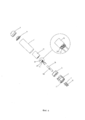
[0027] ФИГ. 1 представляет собой вид спереди электронной сигареты по настоящему изобретению в вертикальном разрезе;FIG. 1 is a front elevational view of an electronic cigarette of the present invention;
[0028] ФИГ. 2 - вид в поперечном разрезе по линии А-А на ФИГ. 1;FIG. 2 is a cross-sectional view along line AA in FIG. one;
[0029] ФИГ. 3 - увеличенный вид участка М, указанного на ФИГ. 2;FIG. 3 is an enlarged view of a portion M indicated in FIG. 2;
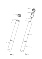
[0030] ФИГ. 4 - вид в разобранном состоянии всасывающей насадки электронной сигареты по настоящему изобретению;FIG. 4 is an exploded view of a suction nozzle of an electronic cigarette of the present invention;
[0031] ФИГ. 5 - вид в разобранном состоянии насадки для аккумуляторной батареи электронной сигареты по настоящему изобретению;FIG. 5 is an exploded view of a nozzle for an electronic cigarette battery pack of the present invention;
[0032] ФИГ. 6 - первый вид в перспективе крышки стакана для сигаретной жидкости всасывающей насадки по настоящему изобретению;FIG. 6 is a first perspective view of a cap for a cigarette liquid of a suction nozzle of the present invention;
[0033] ФИГ. 7 - второй вид в перспективе крышки стакана для сигаретной жидкости всасывающей насадки по настоящему изобретению;FIG. 7 is a second perspective view of a cap of a glass for a cigarette liquid of a suction nozzle of the present invention;
[0034] ФИГ. 8 - вид в поперечном разрезе седла стакана для сигаретной жидкости всасывающей насадки по настоящему изобретению;FIG. 8 is a cross-sectional view of a saddle of a nozzle cup for a cigarette liquid of the present invention;
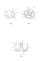
[0035] ФИГ. 9 - вид в перспективе охватываемого соединительного элемента всасывающей насадки по настоящему изобретению;FIG. 9 is a perspective view of a male connector of a suction nozzle of the present invention;
[0036] ФИГ. 10 - вид в поперечном разрезе охватываемого соединительного элемента всасывающей насадки по настоящему изобретению;FIG. 10 is a cross-sectional view of a male connection member of a suction nozzle of the present invention;
[0037] ФИГ. 11 - вид в перспективе охватывающего соединительного элемента всасывающей насадки по настоящему изобретению;FIG. 11 is a perspective view of a female connector of a suction nozzle of the present invention;
[0038] ФИГ. 12 - вид в поперечном разрезе охватывающего соединительного элемента всасывающей насадки по настоящему изобретению;FIG. 12 is a cross-sectional view of the female connector of the suction nozzle of the present invention;
[0039] ФИГ. 13 - вид в перспективе первого электродного элемента распыляющего устройства всасывающей насадки по настоящему изобретению;FIG. 13 is a perspective view of a first electrode element of a spray device of a suction nozzle of the present invention;
[0040] ФИГ. 14 - вид в перспективе первого электродного элемента аккумуляторной батареи насадки для аккумуляторной батареи по настоящему изобретению;FIG. 14 is a perspective view of a first battery cell electrode member of a battery pack of the present invention;
[0041] ФИГ. 15 - первый вид в перспективе опорного основания насадки для аккумуляторной батареи по настоящему изобретению;FIG. 15 is a first perspective view of a support base of a battery nozzle of the present invention;
[0042] ФИГ. 16 - второй вид в перспективе опорного основания насадки для аккумуляторной батареи по настоящему изобретению;FIG. 16 is a second perspective view of a support base of a nozzle for a battery of the present invention;
[0043] ФИГ. 17 - схематичный вид, иллюстрирующий состояние, в котором соединительное устройство смонтировано на опорном основании, в соответствии с настоящим изобретением;FIG. 17 is a schematic view illustrating a state in which a connecting device is mounted on a support base in accordance with the present invention;
[0044] ФИГ. 18 - вид в поперечном разрезе по ФИГ. 17;FIG. 18 is a cross-sectional view of FIG. 17;
[0045] ФИГ. 19 - схематичный вид, иллюстрирующий состояние, в котором соединительное устройство вытянуто из опорного основания, в соответствии с настоящим изобретением;FIG. 19 is a schematic view illustrating a state in which a connecting device is elongated from a support base in accordance with the present invention;
[0046] ФИГ. 20 - вид в поперечном разрезе по ФИГ. 19;FIG. 20 is a cross-sectional view of FIG. 19;
[0047] ФИГ. 21 - схематичный вид, иллюстрирующий состояние, в котором нижний кожух вытянут из насадки для аккумуляторной батареи, в соответствии с настоящим изобретением;FIG. 21 is a schematic view illustrating a state in which a lower case is pulled out of a battery nozzle in accordance with the present invention;
[0048] ФИГ. 22 - схематичный вид, иллюстрирующий состояние, в котором соединительное устройство вытянуто из насадки для аккумуляторной батареи, в соответствии с настоящим изобретением; иFIG. 22 is a schematic view illustrating a state in which a connecting device is pulled out of a nozzle for a battery in accordance with the present invention; and
[0049] ФИГ. 23 - схематичный вид, иллюстрирующий состояние, в котором всасывающая насадка вытянута из насадки для аккумуляторной батареи.FIG. 23 is a schematic view illustrating a state in which a suction nozzle is pulled out of a battery nozzle.
ОПИСАНИЕ ПРЕДПОЧТИТЕЛЬНЫХ ВАРИАНТОВ ОСУЩЕСТВЛЕНИЯDESCRIPTION OF PREFERRED EMBODIMENTS
[0050] Как показано на ФИГ. с 1 по 23, первый вариант осуществления настоящего изобретения предлагает электронную сигарету, содержащую корпус сигареты, с имеющейся всасывающей насадкой 90 и насадкой для аккумуляторной батареи 91. Корпус сигареты снабжен втягивающимся соединительным устройством 7. Соединительное устройство 7 размещено с возможностью втягивания в корпус сигареты так, чтобы оно могло быть скрыто в нем. В промежутках между эксплуатацией, соединительное устройство 7, складываясь, втягивается, чтобы быть полностью скрытым внутри корпуса сигареты. При использовании соединительное устройство 7 вытягивают, чтобы удлинить его до заранее определенной величины, тем самым, электрически подключая электронную сигарету к внешнему электронному устройству или источнику питания. Соединительное устройство 7 предназначено для зарядки электронной сигареты, а также для передачи данных, таких, как мультимедийные данные, чтобы соответствовать требованиям множества функций электронной сигареты. Соединительное устройство 7, по меньшей мере, содержит коннектор 71 и проводник 72, длина которого может быть увеличена. Коннектор 71 представляет собой один из типов коннекторов - универсальная последовательная шина (USB), коннектор штифтового типа, штыревого типа или другой соответствующий коннектор. Предпочтительный вариант осуществления, описанный ниже, использует в качестве примера коннектор USB 71, чтобы осуществить зарядку электронной сигареты.[0050] As shown in FIG. 1 to 23, the first embodiment of the present invention provides an electronic cigarette comprising a cigarette case with an existing
[0051] Как показано на ФИГ. с 2 по 4, всасывающая насадка 90 содержит всасывающий цилиндр 1, распыляющее устройство 2 для распыления сигаретной жидкости, стакан 3 для сигаретной жидкости, всасывающее сопло 4, и охватываемый соединительный элемент 5 для подсоединения насадки с аккумуляторной батареей 91. В этом варианте осуществления всасывающий цилиндр 1 представляет собой удлиненную трубчатую конструкцию, при этом всасывающее сопло 4 и охватываемый соединительный элемент 5 смонтированы на противоположных концевых участках всасывающего цилиндра 1.[0051] As shown in FIG. 2 to 4, the
[0052] Как показано на ФИГ. 3, всасывающее сопло 4 имеет, по существу, цилиндрический корпус 41, полый внутри и имеющий всасывающее отверстие 42, проходящее в цилиндрическом корпусе 41 в его осевом направлении 41. Всасывающее сопло 4 выполнено из упругого материала, и вставлено с возможностью разъема в верхний конец всасывающего цилиндра 1.[0052] As shown in FIG. 3, the
[0053] Как показано на ФИГ. 3, 4, 9 и 10, охватываемый соединительный элемент 5, выполненный из гибкого материала, расположен на дне всасывающего цилиндра 1 и имеет форму, согласующуюся с формой всасывающего цилиндра 1. Охватываемый соединительный элемент 5, по существу, выполнен в форме круглой крышки, полой внутри, с множеством отверстий для впуска воздуха 51, выполненных в ее днище вдоль периферийных ребер охватываемого соединительного элемента 5, для обеспечения возможности попадания наружного воздуха во всасывающий цилиндр 1. Установочная ступенька 52 образована путем создания радиального выступа наружу от днища охватываемого соединительного элемента 5 для упора в днище всасывающего цилиндра 1. Первая принимающая камера 53 образована на днище охватываемого соединительного элемента 5 для обеспечения плотного монтажа на насадке для аккумуляторной батареи 91. Прорези для электродов 54 и воздушные отверстия 55, соответственно, выполнены на среднем участке охватываемого соединительного элемента 5 и проходят сквозь охватываемый соединительный элемент 5 в его осевом направлении. Установочный выступ 56 выполнен на днище охватываемого соединительного элемента 5 и проходит наружу в осевом направлении для вставки в насадку для аккумуляторной батареи 91.[0053] As shown in FIG. 3, 4, 9, and 10, a
[0054] Как показано на ФИГ. 3, 4 и 13, всасывающий цилиндр 1 дополнительно содержит первый электродный элемент распыляющего устройства 17 и второй электродный элемент распыляющего устройства 19 для электрического подключения электродов насадки для аккумуляторной батареи 91. Оба электродных элемента распыляющего устройства - первый 17 и второй 19 - расположены в охватываемом соединительном элементе 5. Первый электродный элемент 17 распыляющего устройства представляет собой гибко деформируемый металлический лист, снабженный припаиваемой пластиной 171 на одном своем конце, в припаиваемой пластине 171 выполнено отверстие, гибкой контактной пластиной 172, гибко деформируемой и установленной на другом конце, и взаимодействующей пластиной 173, гибко деформируемой и установленной в середине первого электродного элемента 17 распыляющего устройства для взаимодействия с охватываемым соединительным элементом 5. Второй электродный элемент 19 распыляющего устройства имеет точно такую же конструкцию, что и первый электродный элемент 17 распыляющего устройства.[0054] As shown in FIG. 3, 4 and 13, the suction cylinder 1 further comprises a first electrode element of the
[0055] Как показано на ФИГ. с 3 по 5, распыляющее устройство 2 содержит распылитель 21, установленный во всасывающей насадке 90, переключатель распылителя 27, основание переключателя 28, и блок управляющего контура для управления распылителем 21.[0055] As shown in FIG. 3 through 5, the
[0056] Распылитель 21 предназначен для распыления сигаретной жидкости до состояния дыма, и содержит нагревательный элемент 211 и волокнистые элементы 212. Нагревательный элемент 211 навит на волокнистые элементы 212 и удерживается в стакане для сигаретной жидкости 3. Волокнистые элементы 212 предназначены для абсорбирования сигаретной жидкости, подлежащей нагреву нагревательным элементом 211 и распылению. Волокнистые элементы 212 функционируют как губка, способная абсорбировать и сохранять воду, и выполнены из стекловолокна или из материала, имеющего характеристики абсорбирования и изолирования жидкости, такого как хлопок, и имеют трубчатую форму. В этом варианте осуществления, количество волокнистых элементов 212 равно трем (это не является ограничением). Три волокнистых элемента 212, как одно целое, размещены в стакане для сигаретной жидкости 3. Нагревательный элемент 211 навит на наружные поверхности всех трех волокнистых элементов 212, при этом, два противоположных конца нагревательного элемента 211, соответственно, выходят из стакана для сигаретной жидкости 3 для электрического подключения к первому электродному элементу 17 распылителя и второму электродному элементу 19 распылителя охватываемого соединительного элемента 5.[0056] The
[0057] Как показано на ФИГ. 3 и 4, стакан для сигаретной жидкости 3 содержит седло стакана 31, крышку стакана 33, направляющую трубку 35, элемент для хранения жидкости 37, и установочную трубку 39. Седло стакана 31 и крышка стакана 33 разнесены друг от друга на заранее заданное расстояние и взаимодействуют по прессовой посадке с внутренними стенками всасывающего цилиндра 1. Направляющая трубка 35 смонтирована между седлом стакана 31 и крышкой стакана 33. Элемент для хранения жидкости 37 расположен снаружи направляющей трубки 35 между седлом стакана 31 и крышкой стакана 33. Установочная трубка 39 предназначена для установки распылителя 21.[0057] As shown in FIG. 3 and 4, the cigarette
[0058] В этом варианте осуществления седло стакана 31 (обращаясь к ФИГ. 3, 4 и 8) имеет форму цилиндрического стакана, с круглой боковой стенкой 318, круглым днищем стакана 319, установочная стойка 311 проходит в осевом направлении седла стакана 31 от центра днища стакана 319, при этом, круглая боковая стенка 318 и установочная стойка 311 совместно образуют круглую внутреннюю камеру 317. Воздушный канал 312 выполнен в установочной стойке 311 и проходит сквозь установочную стойку 311 и днище стакана 319 в осевом направлении. Множество резьбовых каналов 313 выполнено в днище стакана 319 для прохода сквозь него нагревательного элемента 211. Наружная поверхность боковой стенки 318 выполнена с кольцом 314, установленным по прессовой посадке. Седло стакана 31 плотно подогнано к внутренней стенке всасывающего цилиндра 1 с боковой стенкой 318 и кольцом 314 по прессовой посадке.[0058] In this embodiment, the seat of the cup 31 (referring to FIGS. 3, 4 and 8) is in the form of a cylindrical cup, with a
[0059] Крышка стакана 33 (обращаясь к ФИГ. 3, 4, 6 и 7) выполнена из силикагеля, и имеет форму и размер, соответствующие внутренней стенке всасывающего цилиндра 1. В этом варианте осуществления крышка стакана 33 выполнена полой и цилиндрической, и имеет боковую стенку 338 и верхнюю стенку 339, совместно образующие кольцевую внутреннюю полость 337, внутренний диаметр которой больше наружного диаметра направляющей трубки 35, для обеспечения возможности прохождения дыма. Множество воздушных отверстий 336 выполнены на боковой стенке крышки стакана 33, они сообщаются с кольцевой внутренней полостью 337. Множество ребер 335 выполнено на верхней стенке 339, с расположением в кольцевой внутренней полости 337. В этом варианте осуществления выполнено три ребра 335, радиально расположенных на среднем участке верхней стенки 339, при этом, когда направляющая втулка 35 взаимодействует с ребрами 224, верхний конец направляющей трубки 35 и верхняя стенка 339 совместно образуют зазор, служащий траекторией для сообщения с атмосферой 334, сообщенный с кольцевой внутренней полостью 337. Низ боковой стенки 338 выступает радиально наружу с образованием фланцевого участка 333, имеющего множественные дуговые вырезы 332, что делает фланцевый участок 333 зазубренным. Наружный диаметр фланцевого участка 333 чуть больше внутреннего диаметра всасывающего цилиндра 1. Крышка стакана 33 плотно подогнана к внутренней стенке всасывающего цилиндра 1 посредством фланцевого участка 333. Кольцевая внутренняя полость 337 крышки стакана 33 соответствует установочной стойке 311 седла стакана 31, и оба этих элемента, соответственно, обеспечивают установку противоположных концов направляющей трубки 35. Фланцевый участок 333 крышки стакана 33 и круглая внутренняя камера 317 седла стакана 31, соответственно, фиксируют два противоположных конца элемента для хранения жидкости 37. Когда сигаретной жидкости остается мало, можно вытянуть всасывающее сопло 4, а крышка стакана 33 остается на прежнем месте, при этом объем сигаретной жидкости в стакане для сигаретной жидкости 3 может быть пополнен через дуговые вырезы 332 крышки стакана 33. Сигаретная жидкость абсорбируется элементом для хранения жидкости 37, при этом, ее объем может неоднократно пополняться удобным образом.[0059] The lid of the cup 33 (referring to FIGS. 3, 4, 6 and 7) is made of silica gel and has a shape and size corresponding to the inner wall of the suction cylinder 1. In this embodiment, the lid of the
[0060] Направляющая трубка 35 (обращаясь к ФИГ. 3 и 4) предназначена для опоры элемента для хранения жидкости 37 и волокнистых элементов 212 и ограничения высоты стакана для сигаретной жидкости 3, и дополнительно служит траекторией к наружному пространству всасывающего цилиндра 1, обеспечивая течение дыма, получаемого распылителем 21, распыляющим сигаретную жидкость. В этом варианте осуществления, направляющая трубка 35 представляет собой изолирующий полый цилиндр, выполненный из пластмассы или волокнистого материала, такого как стекловолоконная втулка. У направляющей трубки 35 имеются верхний и нижний концы, при этом, верхний конец смонтирован в кольцевой внутренней полости 337 крышки стакана 33, а нижний конец плотно смонтирован на установочной стойке 311 седла стакана 31. Направляющая трубка 35 выполнена с удерживающим пазом 351, проходящим сквозь боковые стенки направляющей трубки 35 в радиальном направлении для удержания волокнистых элементов 212.[0060] The guide tube 35 (referring to FIGS. 3 and 4) is designed to support the
Волокнистые элементы 212 зафиксированы в удерживающем пазу 351 двумя концами волокнистых элементов 212, упирающимися в элемент для хранения жидкости 37 так, чтобы абсорбировать сигаретную жидкость, подлежащую распылению с участием нагревательного элемента 211.The
[0061] Элемент для хранения жидкости 37 (обращаясь к ФИГ. 3 и 4) предназначен для абсорбирования и хранения сигаретной жидкости в стакане для сигаретной жидкости 3, чтобы обеспечить возможность распылителю 21 распылять сигаретную жидкость. Элемент для хранения жидкости 37 функционирует как губка, то есть, способен абсорбировать и сохранять воду, и выполнен из стекловолокна или из материала с характеристиками абсорбирования и изолирования жидкости, такого как хлопок. Элемент для хранения жидкости 37 представляет собой полую цилиндрическую конструкцию и расположен снаружи направляющей трубки 35. Один конец элемента для хранения жидкости 37 вставлен в круглую внутреннюю камеру 317 седла стакана 31, а другой его конец упирается в дно крышки стакана 33 таким образом, что элемент для хранения жидкости 37 расположен между седлом стакана 31 и крышкой стакана 33. Два конца волокнистых элементов 212 упираются во внутренние стенки элемента для хранения жидкости 37, чтобы абсорбировать сигаретную жидкость, подлежащую нагреву нагревательным элементом 211 и распылению.[0061] The liquid storage member 37 (referring to FIGS. 3 and 4) is for absorbing and storing the cigarette liquid in the cigarette
[0062] Установочная трубка 39 (обращаясь к ФИГ. 3 и 4) предназначена для обеспечения положения распылителя 21 по отношению к направляющей трубке 354. Установочная трубка 39 представляет собой изолирующий полый цилиндр, монтируемый на наружных стенках направляющей трубки 35, и выполненный из пластмассы или волокнистого материала, такого как стекловолоконная втулка. Установочная трубка 39 и направляющая трубка 35 установлены по прессовой посадке относительно друг друга. Дно установочной трубки 39 упирается в распылитель 21 для предотвращения перемещения распылителя 21 в осевом направлении направляющей трубки 35.[0062] The mounting tube 39 (referring to FIGS. 3 and 4) is designed to ensure the position of the
[0063] В этом варианте осуществления, стакан для сигаретной жидкости 3 создает траекторию для дыма, образованную совместно воздушным каналом 312 седла стакана 31, полым проходом в направляющей трубке 35, вентиляционной траекторией 334 крышки стакана 33, кольцевой внутренней полостью 337 и вентиляционными отверстиями 336.[0063] In this embodiment, the cigarette
[0064] Как показано на ФИГ. 2, 3 и 5, насадка для аккумуляторной батареи 91 содержит гильзу 910, охватывающий соединительный элемент 911, и нижний кожух 912, соответственно, смонтированные на противоположных концах гильзы 910, аккумуляторную батарею 913, установленную в гильзе 910, первый электродный элемент 914 аккумуляторной батареи и второй электродный элемент 915 аккумуляторной батареи, электрически подключенные к двум электродам аккумуляторной батареи 913.[0064] As shown in FIG. 2, 3 and 5, the nozzle for the
[0065] Как показано на ФИГ. 3, 11 и 12, охватывающий соединительный элемент 911 выполнен так, чтобы совмещаться с охватываемым соединительным элементом 5, и изготовлен из гибкого пластикового материала. Охватывающий соединительный элемент 911 смонтирован на одном конце охватываемого соединительного элемента 5 так, чтобы обеспечивать соединение всасывающей насадки 90 и насадки с аккумуляторной батареей 91. Охватывающий соединительный элемент 911, по существу, имеет форму круглой крышки и содержит боковую стенку 9111, верхнюю стенку 9112, при этом, внутренняя камера 9119 образована боковой стенкой 9111 и верхней стенкой 9112, фиксирующая ступенька 9113 образована на боковой стенке 9111, примыкает к верхней стенке 9112 и проходит радиально наружу от охватывающего соединительного элемента 911 для крепления к цилиндру 910, при этом, на верхней стенке 9112 расположен вставляемый выступ 9114, проходящий наружу в осевом направлении охватывающего соединительного элемента 911 для вставки в первую принимающую камеру 53 охватываемого соединительного элемента 5. Верхняя стенка 9112 выполнена вогнутой с множеством установочных канавок 9115 для размещения установочного выступа 56 охватываемого соединительного элемента 5. В охватывающем соединительном элементе 911 выполнены резьбовые отверстия 9116, проходящие в нем в осевом направлении, при этом две прорези 9117 для электродов и внутренние каналы 9118 проходят в осевом направлении для установки первого электродного элемента аккумуляторной батареи 914 и второго электродного элемента аккумуляторной батареи 915. Два внутренних канала 9118 служат для вставки первого и второго электродных элементов 17 и 19 распылителя, с которыми во внутренних каналах 9118 находятся в гибком контакте первый и второй электродные элементы 914 и 915 аккумуляторной батареи.[0065] As shown in FIG. 3, 11 and 12, the
[0066] Как показано на ФИГ. 2 и 5, нижний кожух 912 смонтирован на нижнем конце цилиндра 910 для герметизации коннектора USB 71. Нижний кожух 912 дополнительно оснащен уплотнительным кольцом 916. Понятно, что для предотвращения снятия нижнего кожуха 912 с цилиндра 910 или его утери после вытягивания, нижний кожух 912 дополнительно объединен с соединительным ремнем для присоединения к цилиндру 910. Соединительный ремень может быть размещен в цилиндре 910 или выполнен за одно целое с соединительным участком или другой соединительной конструкцией, чтобы смонтировать нижний кожух 912 на цилиндре.[0066] As shown in FIG. 2 and 5, the
[0067] Как показано на ФИГ. 3, 4 и 14, первый и второй электродные элементы аккумуляторной батареи 914 и 915, соответственно, расположены в прорезях для электродов 9117. Первый электродный элемент 914 аккумуляторной батареи представляет собой гибко деформируемый металлический лист, и имеет припаиваемую пластину 9141 с отверстием на одном конце первого электродного элемента 914 аккумуляторной батареи, гибкую контактную пластину 9142, гибко деформируемую и установленную на другом его конце, и взаимодействующую пластину 9143, гибко деформируемую и установленную на его середине для взаимодействия с охватывающим соединительным элементом 911. Второй электродный элемент аккумуляторной батареи 915 имеет точно такую же конструкцию, что и первый электродный элемент аккумуляторной батареи 914. Когда всасывающая насадка 90 и насадка для аккумуляторной батареи 91 совместно вставлены, первый и второй электродные элементы 914 и 915 аккумуляторной батареи охватывающего соединительного элемента 911 находятся в нежестком контакте с первым и вторым электродными элементами 17 и 19 распылителя, осуществляя при этом электрическое подключение. Первый и второй электродные элементы 914 и 915 аккумуляторной батареи, соответственно, электрически подключаются к положительному и отрицательному электродам аккумуляторной батареи 913 через припаиваемые пластины 9141 и отверстия. Первый и второй электродные элементы 17 и 19 распылителя находятся в нежестком контакте с первым и вторым электродными элементами 914 и 915 аккумуляторной батареи через гибкие контактные пластины для осуществления электрического подключения. Соответственно, сборка электронной сигареты может быть выполнена удобным образом, с упрощенными приемами, не требующими большого умения, обеспечивая надежное электрическое подключение.[0067] As shown in FIG. 3, 4 and 14, the first and second electrode elements of the
[0068] Как показано на Фиг. 3 и 5, в этом варианте осуществления, переключатель распыляющего устройства 27 и основание переключателя 28 расположены в насадке для аккумуляторной батареи 91. А именно, переключатель распыляющего устройства 27 расположен в основании переключателя 28, тогда как основание переключателя 28 расположено во внутренней камере 9119 охватывающего соединительного элемента 911. Два электрода переключателя распыляющего устройства 27 электрически подсоединены к первому и второму электродным элементам 914 и 915 аккумуляторной батареи посредством двух проводов (не показаны). Переключатель распыляющего устройства 27 представляет собой переключатель пневматического типа, который может переключаться, в соответствии с пневматической вибрацией при включении или выключении питания. Переключатель распыляющего устройства 27 и аккумуляторная батарея 913 электрически подсоединены к блоку управляющего контура.[0068] As shown in FIG. 3 and 5, in this embodiment, the switch of the
[0069] Как показано на ФИГ. 2, 5, с 15 по 22, соединительное устройство 7 состоит из соединительного устройства 71, проводника 72, и опорного основания 73. В этом варианте осуществления соединительное устройство 7 расположено в насадке для аккумуляторной батареи 91.[0069] As shown in FIG. 2, 5, 15 to 22, the connecting
[0070] Соединительное устройство 71 предназначено для подключения внешней энергии, чтобы зарядить аккумуляторную батарею 911. Коннектор USB 71 способен также передавать, загружать или сохранять мультимедийные данные, когда электронная сигарета оснащена переносными устройствами хранения данных, МР3, МР4 или выполнять другие мультимедийные функции. Соединительное устройство 71 смонтировано в насадке для аккумуляторной батареи 91 посредством опорного основания 73.[0070] The connecting
[0071] Как показано на Фиг. с 15 по 22, опорное основание 73 выполнено, по существу, цилиндрическим, и образует первую принимающую камеру 731, обеспечивающую возможность размещения в ней соединительного устройства 71 и проводника 72. Опорное основание 73 дополнительно выполнено с двумя установочными элементами 735 для установки проводника 72. Два установочных элемента 735 расположены на боковой стенке опорного основания 73, примером каждого из них является винтовой штифт, имеющий внутреннюю винтовую нарезку. На наружной стенке переднего участка опорного основания 73 радиально выполнена установочная ступень 736 для совмещения с днищем цилиндра 910. Нижняя панель 737 выполнена на дне опорного основания 73, и образует сквозное отверстие 738 и проход 739 в нем. Кроме того, наружная стенка опорного основания 73 выполнена с прорезью для проводника (не отмечено).[0071] As shown in FIG. 15 to 22, the
[0072] В этом варианте осуществления первая принимающая камера 731 содержит передний участок 7311, средний участок 7312, и задний участок 7313, все они последовательно соединены друг с другом. Передний участок 7311 выполнен цилиндрическим, для обеспечения возможности прохода наружу или втягивания к опорному основанию 73 коннектора USB 71 и проводника 72. Средний участок 7312 выполнен, по существу, цилиндрическим или имеет другие формы и проходит наружу от поверхности днища переднего участка 7311 в осевом направлении опорного основания 73. Коннектор USB 71 вклинен в средний участок 7312. Задний участок 7313 предназначен для размещения проводника 72, когда проводник 72 втягивается. Задний участок 7313 образован нижней панелью 737 и двумя параллельными зажимными панелями (не показаны), проходящими в осевом направлении. Задний участок 7313 является полым, цилиндрическим или имеет другие формы для размещения проводника 72 и обеспечения возможности свободного перемещения проводника 72 в нем. Проникающее отверстие выполнено между средним участком 7312 и задним участком 7313. Наружная стенка переднего участка 7311 оборудована внутренней стенкой цилиндра 910. Опорное основание 73 смонтировано в цилиндре 910 с плотной пригонкой наружной стенки переднего участка 7311 и цилиндра 910, и установлено посредством установочной ступеньки 736 (обращаясь к ФИГ. 2, 21 и 22). В этом варианте осуществления элементы для установки проводника 735 расположены на наружной стороне среднего участка 7312 первой принимающей камеры 731 и выполнены за одно целое с опорным основанием 73.[0072] In this embodiment, the
[0073] Один конец проводника 72 подсоединен к коннектору USB 71 так, чтобы выступать на приемлемое расстояние от коннектора USB 71. Другой конец проводника 72 подсоединен к блоку управляющего контура, чтобы осуществлять зарядку или выполнять другие функции. Проводник 72 содержит подвижный проводник 721, фиксирующий проводник 722, и соединительный элемент 723 для соединения подвижного проводника 721 и фиксирующего проводника 722. Соединительный элемент 723 установлен посредством внутренней стенки или наружной стенки первой принимающей камеры 731 так, чтобы удерживать фиксирующий проводник 722. Один конец подвижного проводника 721 электрически подключен к фиксирующему проводнику 722 посредством соединительного элемента 723. Другой конец подвижного проводника 721 электрически подключен к коннектору USB 71. Один конец фиксирующего проводника 722 электрически подключен к подвижному проводнику 721 посредством соединительного элемента 723. Другой конец фиксирующего проводника 722 закреплен на наружной стенке опорного основания 73 вдоль прорези для проводника для прохода через отверстие 739 и затем - электрического подключения блока управляющего контура. Фиксирующий проводник 722 закреплен в насадке для аккумуляторной батареи 91 без возможности втягиваться или удлиняться. Соединительный элемент 723 выполнен, по существу, U-образной формы и образует два монтажных отверстия на своих противоположных сторонах для монтажа элементов для установки проводника 735. Соединительный элемент 723 неподвижно смонтирован на элементах установки проводника 735, при этом винты вкручены в элементы установки проводника 735. Альтернативно, соединительный элемент 735 может иметь другие формы и быть смонтирован другими способами. В соответствии с этим фиксирующий проводник 722 проводника 72 установлен и закреплен на месте так, чтобы препятствовать влиянию на электрическое подключение проводника 72 и блока управляющего контура подвижного проводника 721, когда подвижный проводник 721 вытянут.[0073] One end of the
[0074] Когда соединительное устройство 7 не используется, коннектор USB 71 вручную вжимают в опорное основание 73, при этом, монтируют нижний кожух 912, и, таким образом, подвижный проводник 721 помещается в принимающей прорези 732 для проводника, выполненной в опорном основании 73 (обращаясь к ФИГ. 18). При использовании соединительного устройства 7, сначала снимается нижний кожух 912, а затем оттягивается коннектор USB 71 от опорного основания 73, чтобы он вышел из цилиндра 910, при этом, один конец подвижного проводника 721 протягивается из цилиндра 910 из первой принимающей камеры 731 совместно с коннектором USB 71 (обращаясь к ФИГ. 20), а подвижный проводник 721 обеспечивает соединение проводника USB 71 с внешним электронным устройством или источником питания в пределах предварительно определенного расстояния. В этом варианте осуществления количество фиксирующих проводников 722 равно трем, три фиксирующих проводника 722, соответственно, предусмотрены для положительного провода, отрицательного провода и сигнального провода, для соответствующего подключения к соответствующим электродам блока управляющего контура. Соединительное устройство 71 и проводник 72 расположены в насадке с аккумуляторной батареей 91, и, соответственно, обеспечивают удобное использование и красивый внешний вид электронной сигареты. Опорное основание 73 образует первую принимающую камеру 731 для размещения коннектора USB 71 и проводника 72 таким образом, что коннектор USB 71 и проводник 72 могут свободно в ней перемещаться.[0074] When the connecting
[0075] Всасывающая насадка 90 и насадка для аккумуляторной батареи 91 могут взаимодействовать друг с другом или быть вставлены друг в друга. В качестве варианта осуществления, представленного на ФИГ. 23, всасывающая насадка 90 и насадка для аккумуляторной батареи 91 соединены друг с другом с возможностью разъема, посредством охватываемого соединительного элемента 5, на который удобным образом плотно посажен охватывающий соединительный элемент 911. При ином исполнении электронная сигарета по настоящему изобретению выполнена в виде цельного элемента, т.е. всасывающий цилиндр 1 всасывающей насадки 90 и цилиндр 910 насадки для аккумуляторной батареи 91 выполнены за одно целое как корпус в виде одного элемента. Также, всасывающий цилиндр 1, цилиндр 910, и всасывающее сопло 4 выполнены все за одно целое.[0075] The
[0076] Понятно, что изобретение может быть реализовано в иных формах, не выходя за рамки объема, определенного формулой. Таким образом, настоящие примеры и варианты осуществления следует во всех отношениях рассматривать как иллюстративные, а не ограничивающие изобретение, определенное формулой изобретения.[0076] It is understood that the invention may be implemented in other forms without going beyond the scope defined by the claims. Thus, the present examples and embodiments should in all respects be considered as illustrative and not limiting of the invention defined by the claims.
Claims (15)
Applications Claiming Priority (1)
| Application Number | Priority Date | Filing Date | Title |
|---|---|---|---|
| PCT/CN2012/078360 WO2014008623A1 (en) | 2012-07-09 | 2012-07-09 | Electronic cigarette |
Publications (2)
| Publication Number | Publication Date |
|---|---|
| RU2015103964A RU2015103964A (en) | 2015-09-10 |
| RU2598567C2 true RU2598567C2 (en) | 2016-09-27 |
Family
ID=49877567
Family Applications (1)
| Application Number | Title | Priority Date | Filing Date |
|---|---|---|---|
| RU2015103964/12A RU2598567C2 (en) | 2012-07-09 | 2012-07-09 | Electronic cigarette |
Country Status (9)
| Country | Link |
|---|---|
| US (1) | US9386805B2 (en) |
| EP (1) | EP2870887B1 (en) |
| JP (1) | JP5935144B2 (en) |
| KR (1) | KR101802616B1 (en) |
| CN (1) | CN104470385B (en) |
| AU (1) | AU2012385404B2 (en) |
| CA (1) | CA2878505A1 (en) |
| RU (1) | RU2598567C2 (en) |
| WO (1) | WO2014008623A1 (en) |
Families Citing this family (107)
| Publication number | Priority date | Publication date | Assignee | Title |
|---|---|---|---|---|
| US20160345631A1 (en) | 2005-07-19 | 2016-12-01 | James Monsees | Portable devices for generating an inhalable vapor |
| US10159278B2 (en) | 2010-05-15 | 2018-12-25 | Rai Strategic Holdings, Inc. | Assembly directed airflow |
| US9259035B2 (en) | 2010-05-15 | 2016-02-16 | R. J. Reynolds Tobacco Company | Solderless personal vaporizing inhaler |
| US9999250B2 (en) | 2010-05-15 | 2018-06-19 | Rai Strategic Holdings, Inc. | Vaporizer related systems, methods, and apparatus |
| US9743691B2 (en) | 2010-05-15 | 2017-08-29 | Rai Strategic Holdings, Inc. | Vaporizer configuration, control, and reporting |
| US9095175B2 (en) | 2010-05-15 | 2015-08-04 | R. J. Reynolds Tobacco Company | Data logging personal vaporizing inhaler |
| US9861772B2 (en) | 2010-05-15 | 2018-01-09 | Rai Strategic Holdings, Inc. | Personal vaporizing inhaler cartridge |
| US8757147B2 (en) | 2010-05-15 | 2014-06-24 | Minusa Holdings Llc | Personal vaporizing inhaler with internal light source |
| US10136672B2 (en) | 2010-05-15 | 2018-11-27 | Rai Strategic Holdings, Inc. | Solderless directly written heating elements |
| US10517530B2 (en) | 2012-08-28 | 2019-12-31 | Juul Labs, Inc. | Methods and devices for delivering and monitoring of tobacco, nicotine, or other substances |
| CN104010534B (en) * | 2012-11-12 | 2016-04-20 | 惠州市吉瑞科技有限公司 | Electronic cigarette device, electronic cigarette and atomising device thereof |
| US10154691B2 (en) | 2012-11-26 | 2018-12-18 | Nu Mark Innovations Ltd. | Bonding for an electronic cigarette cartridge |
| US10034988B2 (en) | 2012-11-28 | 2018-07-31 | Fontem Holdings I B.V. | Methods and devices for compound delivery |
| US10279934B2 (en) | 2013-03-15 | 2019-05-07 | Juul Labs, Inc. | Fillable vaporizer cartridge and method of filling |
| US9609893B2 (en) | 2013-03-15 | 2017-04-04 | Rai Strategic Holdings, Inc. | Cartridge and control body of an aerosol delivery device including anti-rotation mechanism and related method |
| IL297399B2 (en) | 2013-05-06 | 2024-02-01 | Juul Labs Inc | Nicotine salt formulations for aerosol devices and methods thereof |
| WO2014201432A1 (en) | 2013-06-14 | 2014-12-18 | Ploom, Inc. | Multiple heating elements with separate vaporizable materials in an electric vaporization device |
| USD809189S1 (en) * | 2013-08-23 | 2018-01-30 | Kimree Hi-Tech Inc | Electronic cigarette |
| WO2015042412A1 (en) | 2013-09-20 | 2015-03-26 | E-Nicotine Technology. Inc. | Devices and methods for modifying delivery devices |
| CN105578910B (en) * | 2013-09-25 | 2019-06-28 | 吉瑞高新科技股份有限公司 | A kind of battery bar assembly, electronic cigarette and electronic cigarette charging unit |
| US10980273B2 (en) | 2013-11-12 | 2021-04-20 | VMR Products, LLC | Vaporizer, charger and methods of use |
| WO2015078147A1 (en) * | 2013-11-28 | 2015-06-04 | Hk Triangle Co., Limited | Electronic cigarette atomizer |
| EP3076805A4 (en) | 2013-12-05 | 2017-10-11 | PAX Labs, Inc. | Nicotine liquid formulations for aerosol devices and methods thereof |
| US9549573B2 (en) * | 2013-12-23 | 2017-01-24 | Pax Labs, Inc. | Vaporization device systems and methods |
| USD825102S1 (en) | 2016-07-28 | 2018-08-07 | Juul Labs, Inc. | Vaporizer device with cartridge |
| PT3086671T (en) | 2013-12-23 | 2019-01-23 | Juul Labs Uk Holdco Ltd | Vaporization device systems |
| US20160366947A1 (en) | 2013-12-23 | 2016-12-22 | James Monsees | Vaporizer apparatus |
| USD842536S1 (en) | 2016-07-28 | 2019-03-05 | Juul Labs, Inc. | Vaporizer cartridge |
| US10076139B2 (en) | 2013-12-23 | 2018-09-18 | Juul Labs, Inc. | Vaporizer apparatus |
| US10058129B2 (en) | 2013-12-23 | 2018-08-28 | Juul Labs, Inc. | Vaporization device systems and methods |
| US10159282B2 (en) | 2013-12-23 | 2018-12-25 | Juul Labs, Inc. | Cartridge for use with a vaporizer device |
| CN203762295U (en) * | 2014-01-14 | 2014-08-13 | 深圳市合元科技有限公司 | Battery pack used for electronic cigarette and electronic cigarette |
| WO2015106440A1 (en) * | 2014-01-17 | 2015-07-23 | 深圳市麦克韦尔科技有限公司 | Electronic cigarette connection structure and electronic cigarette |
| US9993024B2 (en) * | 2014-01-22 | 2018-06-12 | Huizhou Kimree Technology Co., Ltd. Shenzhen Branch | Battery rod and electronic cigarette |
| EP2907398A1 (en) * | 2014-01-27 | 2015-08-19 | Shenzhen Smaco Technology Limited | Disposable electronic cigarette |
| US10709173B2 (en) | 2014-02-06 | 2020-07-14 | Juul Labs, Inc. | Vaporizer apparatus |
| TWI828016B (en) | 2014-02-06 | 2024-01-01 | 美商尤爾實驗室有限公司 | An electronic device for generating an inhalable vapor, a system, and a kit comprising the electronic device |
| CN203723447U (en) * | 2014-02-12 | 2014-07-23 | 刘秋明 | Atomization component and electronic cigarette |
| DE202014001718U1 (en) * | 2014-02-27 | 2015-05-28 | Xeo Holding GmbH | smoking device |
| US10111467B1 (en) | 2014-03-24 | 2018-10-30 | Scott M. Arnel | Wearable electronic simulated smoking device with interchangeable vaporization cartridges |
| US9820508B2 (en) | 2014-03-24 | 2017-11-21 | Scott M. Arnel | Wearable electronic simulated smoking device |
| CN103892467B (en) * | 2014-04-02 | 2016-04-20 | 林光榕 | Oval electronic cigarette and manufacturing process thereof |
| USD743622S1 (en) * | 2014-04-02 | 2015-11-17 | Yariv Alima | Vaporizer body |
| DE102014207277A1 (en) * | 2014-04-15 | 2015-10-15 | Hauni Maschinenbau Ag | Electric smoking product and device for the production of electrical smoke products |
| US11478021B2 (en) | 2014-05-16 | 2022-10-25 | Juul Labs, Inc. | Systems and methods for aerosolizing a vaporizable material |
| CN205667357U (en) * | 2014-07-21 | 2016-11-02 | 惠州市吉瑞科技有限公司 | A kind of electronic cigarette |
| US20160128387A1 (en) * | 2014-08-29 | 2016-05-12 | Shenzhen Smoore Technology Limited | Electronic cigarette and method for manufacturing electronic cigarette |
| WO2016074236A1 (en) * | 2014-11-14 | 2016-05-19 | 惠州市吉瑞科技有限公司 | Electronic cigarette and electronic cigarette atomization control method |
| CN112155255A (en) | 2014-12-05 | 2021-01-01 | 尤尔实验室有限公司 | Corrective dose control |
| CN204444245U (en) * | 2015-01-05 | 2015-07-08 | 深圳市合元科技有限公司 | Removable atomization unit and the atomizer and the electronic cigarette that comprise this atomization unit |
| GB201501429D0 (en) * | 2015-01-28 | 2015-03-11 | British American Tobacco Co | Apparatus for heating aerosol generating material |
| EP3056099B1 (en) * | 2015-02-16 | 2018-04-04 | Fontem Holdings 1 B.V. | Electronic smoking device with snap-in locking connection |
| CN104824848B (en) * | 2015-03-10 | 2018-04-03 | 深圳麦克韦尔股份有限公司 | Electronic cigarette |
| US10980275B2 (en) | 2015-04-02 | 2021-04-20 | Philip Morris Products S.A. | Kit comprising a module and an electrically operated aerosol-generating system |
| USD874059S1 (en) | 2015-04-22 | 2020-01-28 | Altria Client Servies Llc | Electronic vaping device |
| US10687554B2 (en) | 2015-04-22 | 2020-06-23 | Altria Client Services Llc | Connection device, cartridge and electronic vaping device |
| USD874720S1 (en) | 2015-04-22 | 2020-02-04 | Altria Client Services, Llc | Pod for an electronic vaping device |
| US10671031B2 (en) | 2015-04-22 | 2020-06-02 | Altria Client Services Llc | Body gesture control system for button-less vaping |
| US10064432B2 (en) | 2015-04-22 | 2018-09-04 | Altria Client Services Llc | Pod assembly, dispensing body, and E-vapor apparatus including the same |
| US10104913B2 (en) | 2015-04-22 | 2018-10-23 | Altria Client Services Llc | Pod assembly, dispensing body, and E-vapor apparatus including the same |
| USD980507S1 (en) | 2015-04-22 | 2023-03-07 | Altria Client Services Llc | Electronic vaping device |
| US10701981B2 (en) | 2015-04-22 | 2020-07-07 | Altria Client Services Llc | Pod assembly and e-vapor apparatus including the same |
| US10010114B2 (en) | 2015-06-25 | 2018-07-03 | Altria Client Services Llc | Charger assembly and charging system for an electronic vaping device |
| CN104983073A (en) * | 2015-07-07 | 2015-10-21 | 深圳市赛尔美电子科技有限公司 | Cigarette distilling device |
| KR102405408B1 (en) * | 2015-07-16 | 2022-06-07 | 삼성전자 주식회사 | Apparatus and method for communicating channel state information in full-dimensional mimo system |
| CN205305994U (en) * | 2015-12-24 | 2016-06-15 | 林光榕 | Electronic cigarette atomization device |
| BR112018016402B1 (en) | 2016-02-11 | 2023-12-19 | Juul Labs, Inc | SECURELY FIXED CARTRIDGES FOR VAPORIZER DEVICES |
| MX2018009702A (en) | 2016-02-11 | 2019-07-08 | Juul Labs Inc | Fillable vaporizer cartridge and method of filling. |
| US11412781B2 (en) * | 2016-02-12 | 2022-08-16 | Rai Strategic Holdings, Inc. | Adapters for refilling an aerosol delivery device |
| EP3419449B1 (en) | 2016-02-25 | 2020-09-23 | Juul Labs, Inc. | Vaporization device control systems and methods |
| US10405582B2 (en) | 2016-03-10 | 2019-09-10 | Pax Labs, Inc. | Vaporization device with lip sensing |
| US10264821B2 (en) | 2016-03-21 | 2019-04-23 | Altria Client Services Llc | Electronic vaping device |
| USD849996S1 (en) | 2016-06-16 | 2019-05-28 | Pax Labs, Inc. | Vaporizer cartridge |
| USD851830S1 (en) | 2016-06-23 | 2019-06-18 | Pax Labs, Inc. | Combined vaporizer tamp and pick tool |
| USD836541S1 (en) | 2016-06-23 | 2018-12-25 | Pax Labs, Inc. | Charging device |
| USD848057S1 (en) | 2016-06-23 | 2019-05-07 | Pax Labs, Inc. | Lid for a vaporizer |
| US10292426B2 (en) | 2016-06-24 | 2019-05-21 | Altria Client Services, Llc | E-vaping device cartridge with superabsorbent polymer |
| US10383367B2 (en) | 2016-07-25 | 2019-08-20 | Fontem Holdings 1 B.V. | Electronic cigarette power supply portion |
| USD830298S1 (en) | 2016-07-29 | 2018-10-09 | Altria Client Services Llc | USB charging connector for electronic vaporizer |
| WO2018018599A1 (en) * | 2016-07-29 | 2018-02-01 | 深圳麦克韦尔股份有限公司 | Electronic cigarette and atomizer thereof |
| US10729177B2 (en) * | 2016-07-31 | 2020-08-04 | Altria Client Services Llc | Electronic vaping device, battery section, and charger |
| US11825881B2 (en) * | 2016-09-15 | 2023-11-28 | Philip Morris Products S.A. | Aerosol-generating device providing secure retention for aerosol-generating articles |
| US11660403B2 (en) | 2016-09-22 | 2023-05-30 | Juul Labs, Inc. | Leak-resistant vaporizer device |
| CN106235422A (en) * | 2016-09-29 | 2016-12-21 | 深圳市博格科技有限公司 | A kind of oil dripping type nebulizer and electronic cigarette |
| CA185558S (en) * | 2016-09-30 | 2019-02-14 | Fontem Holdings 1 Bv | Electronic vaping device |
| WO2018102703A1 (en) | 2016-12-02 | 2018-06-07 | Vmr Products Llc | Combination vaporizer |
| US10701976B2 (en) | 2016-12-12 | 2020-07-07 | VMR Products, LLC | Vaporizer cartridge |
| EA038750B1 (en) | 2017-05-22 | 2021-10-14 | Олтриа Клайент Сервисиз Ллк | Pod assembly, dispensing body, and e-vapor apparatus including the same |
| USD887632S1 (en) | 2017-09-14 | 2020-06-16 | Pax Labs, Inc. | Vaporizer cartridge |
| CN109965349A (en) * | 2017-12-27 | 2019-07-05 | 上海新型烟草制品研究院有限公司 | A kind of electronic cigarette |
| TW201932031A (en) * | 2017-12-29 | 2019-08-16 | 瑞士商傑太日煙國際股份有限公司 | A smoking device |
| KR20190083581A (en) | 2018-01-04 | 2019-07-12 | 홍성혁 | Cigarette-type evaporative cigarette device |
| PL426350A1 (en) * | 2018-07-18 | 2020-01-27 | Esmoking Institute Spółka Z Ograniczoną Odpowiedzialnością | Electronic aerosol provision system |
| CN108813738A (en) * | 2018-08-10 | 2018-11-16 | 陈志明 | A kind of electronics tobacco rod and electronic cigarette |
| CN108851252A (en) * | 2018-09-25 | 2018-11-23 | 深圳市美深威科技有限公司 | A kind of electronic cigarette battery bar and electronic cigarette |
| SG11202103757VA (en) | 2018-10-15 | 2021-05-28 | Juul Labs Inc | Heating element |
| JP6855434B2 (en) | 2018-12-10 | 2021-04-07 | 有限会社ヘルス・アンド・ヒーリング・オペレーション | Electronic cigarette system |
| EP3925467A4 (en) * | 2019-02-12 | 2022-08-17 | Japan Tobacco Inc. | Cartridge for inhaler |
| EP3738450A1 (en) * | 2019-05-13 | 2020-11-18 | Tuanfang Liu | Vaporizer |
| EP3838009A1 (en) * | 2019-12-20 | 2021-06-23 | Nerudia Limited | Charging device and smoking substitute kit |
| EP4054359A1 (en) * | 2019-11-08 | 2022-09-14 | Nerudia Limited | Charging device and smoking substitute kit |
| KR102423895B1 (en) * | 2019-11-25 | 2022-07-21 | 주식회사 케이티앤지 | Heater assembly, aerosol generating device and aerosol generating system |
| US11602171B2 (en) * | 2019-11-26 | 2023-03-14 | Tuanfang Liu | Electronic cigarette having leakproof device for preventing leakage of e-liquid |
| EP3847912A1 (en) * | 2019-11-26 | 2021-07-14 | Tuanfang Liu | Electronic cigarette |
| US20210401051A1 (en) * | 2020-06-29 | 2021-12-30 | Shenzhen Eigate Technology Co., Ltd. | Atomizer |
| US11930861B2 (en) * | 2020-12-07 | 2024-03-19 | Rai Strategic Holdings, Inc. | Aerosol provision system with integrated charger |
| KR20220165327A (en) | 2021-06-08 | 2022-12-15 | 이서현 | capsule type electric cigarette |
Citations (4)
| Publication number | Priority date | Publication date | Assignee | Title |
|---|---|---|---|---|
| EA000244B1 (en) * | 1995-04-20 | 1999-02-25 | Филип Моррис Продактс Инк. | Cigarette and heater for use in an electrical smoking system |
| US20090283103A1 (en) * | 2008-05-13 | 2009-11-19 | Nielsen Michael D | Electronic vaporizing devices and docking stations |
| UA67598U (en) * | 2011-08-26 | 2012-02-27 | Дмитрий Юрьевич Рогов | Electronic cigarette |
| RU115629U1 (en) * | 2011-10-10 | 2012-05-10 | Сергей Павлович Кузьмин | ELECTRONIC CIGARETTE |
Family Cites Families (18)
| Publication number | Priority date | Publication date | Assignee | Title |
|---|---|---|---|---|
| JP2000049918A (en) * | 1998-08-03 | 2000-02-18 | Fujitsu I Network Systems Ltd | Portable telephone set |
| CN2591886Y (en) * | 2002-12-28 | 2003-12-10 | 杨志刚 | Cellular phone in-circuit device |
| US7632113B2 (en) * | 2003-11-17 | 2009-12-15 | Dpd Patent Trust Ltd. | Retractable USB stick |
| US6926554B2 (en) * | 2003-11-20 | 2005-08-09 | Creative Technology Limited | Portable device connection apparatus and system |
| US20070126290A1 (en) * | 2005-11-01 | 2007-06-07 | Jaynes Stephen R | Systems and methods for powering an electronic device from selectable power sources |
| KR20080030247A (en) * | 2006-09-29 | 2008-04-04 | 엘지전자 주식회사 | Mouse having retractable cable |
| CN200997909Y (en) * | 2006-12-15 | 2008-01-02 | 王玉民 | Disposable electric purified cigarette |
| CN201408820Y (en) * | 2009-04-28 | 2010-02-17 | 慈溪市依赛格电子科技有限公司 | Charging device for electronic cigarette |
| JP2011087569A (en) * | 2009-05-15 | 2011-05-06 | Jbs:Kk | Electronic cigarette and charging unit |
| CN101606758B (en) * | 2009-07-14 | 2011-04-13 | 方晓林 | Electronic cigarette |
| TWM376063U (en) * | 2009-10-19 | 2010-03-11 | Multi Function Co Ltd | Charging/discharging device with hidden type USB plug |
| CN201830899U (en) * | 2010-06-09 | 2011-05-18 | 李永海 | Power supply device for electronic cigarette |
| CN201830900U (en) * | 2010-06-09 | 2011-05-18 | 李永海 | Tobacco juice atomization device for electronic cigarette |
| CN201733855U (en) * | 2010-08-10 | 2011-02-09 | 刘翔 | Electronic cigarette |
| CN102160906B (en) * | 2010-11-01 | 2012-08-08 | 常州市富艾发进出口有限公司 | Oral-suction type portable atomizer |
| KR20120057459A (en) * | 2010-11-26 | 2012-06-05 | 이호준 | Electronic cigarette interfacing with Computer |
| CN202112305U (en) * | 2011-01-27 | 2012-01-18 | 文昌 | Multifunctional electronic smoke generator with storage device |
| KR101081481B1 (en) * | 2011-06-13 | 2011-11-08 | 김형윤 | Cartridge having pulverizer for electronic cigarette |
-
2012
- 2012-07-09 CN CN201280071003.3A patent/CN104470385B/en not_active Expired - Fee Related
- 2012-07-09 WO PCT/CN2012/078360 patent/WO2014008623A1/en active Application Filing
- 2012-07-09 KR KR1020157003216A patent/KR101802616B1/en active IP Right Grant
- 2012-07-09 US US13/824,440 patent/US9386805B2/en not_active Expired - Fee Related
- 2012-07-09 CA CA2878505A patent/CA2878505A1/en not_active Abandoned
- 2012-07-09 RU RU2015103964/12A patent/RU2598567C2/en not_active IP Right Cessation
- 2012-07-09 AU AU2012385404A patent/AU2012385404B2/en not_active Expired - Fee Related
- 2012-07-09 JP JP2015520788A patent/JP5935144B2/en not_active Expired - Fee Related
- 2012-07-09 EP EP12880826.8A patent/EP2870887B1/en not_active Not-in-force
Patent Citations (4)
| Publication number | Priority date | Publication date | Assignee | Title |
|---|---|---|---|---|
| EA000244B1 (en) * | 1995-04-20 | 1999-02-25 | Филип Моррис Продактс Инк. | Cigarette and heater for use in an electrical smoking system |
| US20090283103A1 (en) * | 2008-05-13 | 2009-11-19 | Nielsen Michael D | Electronic vaporizing devices and docking stations |
| UA67598U (en) * | 2011-08-26 | 2012-02-27 | Дмитрий Юрьевич Рогов | Electronic cigarette |
| RU115629U1 (en) * | 2011-10-10 | 2012-05-10 | Сергей Павлович Кузьмин | ELECTRONIC CIGARETTE |
Also Published As
| Publication number | Publication date |
|---|---|
| JP2015523077A (en) | 2015-08-13 |
| RU2015103964A (en) | 2015-09-10 |
| US20140007891A1 (en) | 2014-01-09 |
| CN104470385A (en) | 2015-03-25 |
| AU2012385404B2 (en) | 2017-04-27 |
| EP2870887A4 (en) | 2016-05-18 |
| EP2870887A1 (en) | 2015-05-13 |
| KR101802616B1 (en) | 2017-11-28 |
| JP5935144B2 (en) | 2016-06-15 |
| KR20150030268A (en) | 2015-03-19 |
| WO2014008623A1 (en) | 2014-01-16 |
| CA2878505A1 (en) | 2014-01-16 |
| US9386805B2 (en) | 2016-07-12 |
| CN104470385B (en) | 2017-04-19 |
| EP2870887B1 (en) | 2017-06-28 |
| AU2012385404A1 (en) | 2015-02-26 |
Similar Documents
| Publication | Publication Date | Title |
|---|---|---|
| RU2598567C2 (en) | Electronic cigarette | |
| US9480286B2 (en) | Electronic cigarette device and electronic cigarette thereof | |
| EP3153036B1 (en) | E-cigarette atomizer | |
| US9861133B2 (en) | Electronic cigarette | |
| US9497994B2 (en) | Electronic cigarette device, electronic cigarette, and atomizing device used in the same | |
| US20160113325A1 (en) | Electronic cigarette | |
| RU2602964C2 (en) | Suction rod for electronic cigarette and electronic cigarette using said rod | |
| US9901120B2 (en) | Electronic cigarette with a built-in battery rod | |
| CN204519356U (en) | Magnetic force connects electronic cigarette | |
| US9364026B2 (en) | Electronic cigarette tightly engaged by expansion | |
| CN203168036U (en) | Electronic cigarette device and electronic cigarette thereof | |
| US9155336B2 (en) | Electronic cigarette and electronic cigarette device | |
| US10306930B2 (en) | Heating device, and atomizing head, atomizer and electronic cigarette having the same | |
| WO2014089757A1 (en) | Electronic cigarette and electronic cigarette device thereof | |
| CN104000305A (en) | Electronic cigarette | |
| CN215684865U (en) | Atomizer and aerosol-generating device | |
| CN105661650A (en) | Heating device, atomizing head, atomizer and electronic cigarette of electronic cigarette atomizing head | |
| CN215141121U (en) | Structure of power battery assembly and wireless vehicle washing gun | |
| CN115191663A (en) | Electronic atomization device, atomizer and supporting structure | |
| CN210782938U (en) | Atomization assembly, atomizer and aerosol generating device | |
| CN217883670U (en) | Base station | |
| CN218635316U (en) | Electronic atomization device, atomizer and supporting structure | |
| CN217885121U (en) | Atomizer with split magazine | |
| CN218605070U (en) | Nebulizer and aerosol-generating device | |
| CN213307437U (en) | Cell-phone power supply formula electron cigarette |
Legal Events
| Date | Code | Title | Description |
|---|---|---|---|
| HE9A | Changing address for correspondence with an applicant | ||
| MM4A | The patent is invalid due to non-payment of fees |
Effective date: 20180710 |