RU2602964C2 - Suction rod for electronic cigarette and electronic cigarette using said rod - Google Patents
Suction rod for electronic cigarette and electronic cigarette using said rod Download PDFInfo
- Publication number
- RU2602964C2 RU2602964C2 RU2014148908/12A RU2014148908A RU2602964C2 RU 2602964 C2 RU2602964 C2 RU 2602964C2 RU 2014148908/12 A RU2014148908/12 A RU 2014148908/12A RU 2014148908 A RU2014148908 A RU 2014148908A RU 2602964 C2 RU2602964 C2 RU 2602964C2
- Authority
- RU
- Russia
- Prior art keywords
- liquid
- hole
- smoke
- nozzle
- cigarette
- Prior art date
Links
Images


Classifications
-
- A—HUMAN NECESSITIES
- A24—TOBACCO; CIGARS; CIGARETTES; SIMULATED SMOKING DEVICES; SMOKERS' REQUISITES
- A24F—SMOKERS' REQUISITES; MATCH BOXES; SIMULATED SMOKING DEVICES
- A24F40/00—Electrically operated smoking devices; Component parts thereof; Manufacture thereof; Maintenance or testing thereof; Charging means specially adapted therefor
- A24F40/40—Constructional details, e.g. connection of cartridges and battery parts
- A24F40/46—Shape or structure of electric heating means
-
- A—HUMAN NECESSITIES
- A24—TOBACCO; CIGARS; CIGARETTES; SIMULATED SMOKING DEVICES; SMOKERS' REQUISITES
- A24F—SMOKERS' REQUISITES; MATCH BOXES; SIMULATED SMOKING DEVICES
- A24F40/00—Electrically operated smoking devices; Component parts thereof; Manufacture thereof; Maintenance or testing thereof; Charging means specially adapted therefor
- A24F40/40—Constructional details, e.g. connection of cartridges and battery parts
- A24F40/42—Cartridges or containers for inhalable precursors
-
- A—HUMAN NECESSITIES
- A24—TOBACCO; CIGARS; CIGARETTES; SIMULATED SMOKING DEVICES; SMOKERS' REQUISITES
- A24F—SMOKERS' REQUISITES; MATCH BOXES; SIMULATED SMOKING DEVICES
- A24F47/00—Smokers' requisites not otherwise provided for
-
- A—HUMAN NECESSITIES
- A24—TOBACCO; CIGARS; CIGARETTES; SIMULATED SMOKING DEVICES; SMOKERS' REQUISITES
- A24B—MANUFACTURE OR PREPARATION OF TOBACCO FOR SMOKING OR CHEWING; TOBACCO; SNUFF
- A24B15/00—Chemical features or treatment of tobacco; Tobacco substitutes, e.g. in liquid form
- A24B15/10—Chemical features of tobacco products or tobacco substitutes
- A24B15/16—Chemical features of tobacco products or tobacco substitutes of tobacco substitutes
- A24B15/167—Chemical features of tobacco products or tobacco substitutes of tobacco substitutes in liquid or vaporisable form, e.g. liquid compositions for electronic cigarettes
-
- A—HUMAN NECESSITIES
- A24—TOBACCO; CIGARS; CIGARETTES; SIMULATED SMOKING DEVICES; SMOKERS' REQUISITES
- A24F—SMOKERS' REQUISITES; MATCH BOXES; SIMULATED SMOKING DEVICES
- A24F40/00—Electrically operated smoking devices; Component parts thereof; Manufacture thereof; Maintenance or testing thereof; Charging means specially adapted therefor
- A24F40/10—Devices using liquid inhalable precursors
-
- A—HUMAN NECESSITIES
- A24—TOBACCO; CIGARS; CIGARETTES; SIMULATED SMOKING DEVICES; SMOKERS' REQUISITES
- A24F—SMOKERS' REQUISITES; MATCH BOXES; SIMULATED SMOKING DEVICES
- A24F40/00—Electrically operated smoking devices; Component parts thereof; Manufacture thereof; Maintenance or testing thereof; Charging means specially adapted therefor
- A24F40/40—Constructional details, e.g. connection of cartridges and battery parts
- A24F40/44—Wicks
-
- A—HUMAN NECESSITIES
- A24—TOBACCO; CIGARS; CIGARETTES; SIMULATED SMOKING DEVICES; SMOKERS' REQUISITES
- A24F—SMOKERS' REQUISITES; MATCH BOXES; SIMULATED SMOKING DEVICES
- A24F40/00—Electrically operated smoking devices; Component parts thereof; Manufacture thereof; Maintenance or testing thereof; Charging means specially adapted therefor
- A24F40/40—Constructional details, e.g. connection of cartridges and battery parts
- A24F40/48—Fluid transfer means, e.g. pumps
- A24F40/485—Valves; Apertures
-
- A—HUMAN NECESSITIES
- A61—MEDICAL OR VETERINARY SCIENCE; HYGIENE
- A61M—DEVICES FOR INTRODUCING MEDIA INTO, OR ONTO, THE BODY; DEVICES FOR TRANSDUCING BODY MEDIA OR FOR TAKING MEDIA FROM THE BODY; DEVICES FOR PRODUCING OR ENDING SLEEP OR STUPOR
- A61M15/00—Inhalators
- A61M15/06—Inhaling appliances shaped like cigars, cigarettes or pipes
-
- A—HUMAN NECESSITIES
- A61—MEDICAL OR VETERINARY SCIENCE; HYGIENE
- A61M—DEVICES FOR INTRODUCING MEDIA INTO, OR ONTO, THE BODY; DEVICES FOR TRANSDUCING BODY MEDIA OR FOR TAKING MEDIA FROM THE BODY; DEVICES FOR PRODUCING OR ENDING SLEEP OR STUPOR
- A61M2205/00—General characteristics of the apparatus
- A61M2205/82—Internal energy supply devices
- A61M2205/8206—Internal energy supply devices battery-operated
Abstract
Description
ОБЛАСТЬ ТЕХНИКИ, К КОТОРОЙ ОТНОСИТСЯ ИЗОБРЕТЕНИЕFIELD OF THE INVENTION
[0001] Это изобретение относится к электронным сигаретам, и в частности к электронной сигарете, которая выполнена ультрадлинной и прозрачной.[0001] This invention relates to electronic cigarettes, and in particular to an electronic cigarette that is ultra-long and transparent.
ОПИСАНИЕ ПРЕДПОСЫЛОК СОЗДАНИЯ ИЗОБРЕТЕНИЯDESCRIPTION OF THE BACKGROUND OF THE INVENTION
[0002] Известная всасывающая насадка электронной сигареты содержит: непрозрачный всасывающий цилиндр, резервуар для сигаретной жидкости, расположенный во всасывающем цилиндре и объединенный с всасывающим цилиндром, канал для затяжки, распыляющее устройство, расположенное во всасывающем цилиндре и снабженное нагревательной проволокой и распыляющим стаканом, удлиненный трубчатый элемент для направления жидкого дыма в распыляющее устройство, крышку всасывающего сопла, расположенную на конце всасывающего цилиндра, и канал затяжки для передачи жидкого дыма в распыляющем стакане наружу всасывающего цилиндра через крышку сопла. Один конец трубки для направления жидкости вставлен в резервуар для сигаретной жидкости, другой конец трубки для направления жидкости вставлен в распыляющее устройство, при этом жидкий дым направляют к распыляющему устройству через трубку для направления жидкости. Нагревательная проволока приварена, соответственно, к положительному электроду и отрицательному электроду, с применением технологии клепки с проволокой для сварки или медной трубкой.[0002] A known electronic cigarette suction nozzle comprises: an opaque suction cylinder, a cigarette liquid reservoir located in the suction cylinder and combined with the suction cylinder, a tightening channel, a spray device located in the suction cylinder and equipped with a heating wire and a spray cup, an elongated tubular an element for directing liquid smoke to the spray device, a suction nozzle cover located at the end of the suction cylinder, and a tightening channel for transferring edachi spraying liquid smoke in a glass cylinder through the outside of the suction nozzle cover. One end of the liquid guide tube is inserted into the cigarette liquid tank, the other end of the liquid guide tube is inserted into the spray device, and liquid smoke is directed to the spray device through the liquid guide tube. The heating wire is welded, respectively, to the positive electrode and the negative electrode, using riveting technology with a wire for welding or a copper tube.
[0003] Известные электронные сигареты обладают следующими недостатками: поскольку трубка для направления жидкости вставлена в резервуар для сигаретной жидкости, ее сложно и неудобно устанавливать, при этом установка может легко привести к протечкам, а объем жидкости непросто контролировать. Во-вторых, нагревательная проволока приварена или приклепана к проводящей проволоке заранее, прежде чем ее приваривают к медным электродам распылителя, процесс является усложненным, а установка - не простая. Канал для затяжки расположен со стороны резервуара для сигаретной жидкости и сбоку сообщен с воздухом, это негативно влияет на объем резервирования жидкости в резервуаре для сигаретной жидкости и уменьшает объем резервирования жидкости в резервуаре для сигаретной жидкости. Резервуар для сигаретной жидкости, канал для затяжки и всасывающий цилиндр выполнены за одно целое, таким образом, длина всасывающей насадки электронной сигареты является фиксированной. Дополнительно, известный распыляющий стакан конструктивно состоит из нескольких компонентов, в связи с этим неудобно устанавливать нагревательную проволоку. Всасывающий цилиндр - непрозрачный, при этом за объемом жидкого дыма в резервуаре для сигаретной жидкости невозможно наблюдать, это может обусловить выгорание нагревательной проволоки при опорожнении и появление запаха газа после того, как закончится жидкий дым.[0003] Known electronic cigarettes have the following disadvantages: since the tube for directing the liquid is inserted into the reservoir for the cigarette liquid, it is difficult and inconvenient to install, the installation can easily lead to leaks, and the volume of the liquid is not easy to control. Secondly, the heating wire is welded or riveted to the conductive wire in advance, before it is welded to the copper electrodes of the atomizer, the process is complicated, and the installation is not simple. The tightening channel is located on the side of the cigarette liquid reservoir and is laterally connected to the air, this negatively affects the volume of liquid reservation in the cigarette liquid reservoir and reduces the volume of liquid reservation in the cigarette liquid reservoir. The cigarette liquid reservoir, the puff channel and the suction cylinder are integrally formed, so that the length of the suction nozzle of the electronic cigarette is fixed. Additionally, the known spray cup is structurally composed of several components, and therefore it is inconvenient to install a heating wire. The suction cylinder is opaque, while it is impossible to observe the volume of liquid smoke in the cigarette liquid tank, this may cause the heating wire to burn out when emptied and there is a gas odor after the liquid smoke has finished.
КРАТКОЕ ИЗЛОЖЕНИЕ СУЩНОСТИ ИЗОБРЕТЕНИЯSUMMARY OF THE INVENTION
[0004] Целью настоящего изобретения является создание всасывающей насадки электронной сигареты, удобной для установки и обеспечивающей хороший дренаж и герметичность, возможное упрощение процесса изготовления всасывающей насадки электронной сигареты, имеющей регулируемую длину и объем резервирования жидкости; объем резервирования жидкого дыма можно увеличить, обеспечивая относительный объем всасывающей насадки электронной сигареты.[0004] An object of the present invention is to provide an electronic cigarette suction nozzle convenient for installation and providing good drainage and tightness, possibly simplifying the manufacturing process of an electronic cigarette suction nozzle having an adjustable length and volume of liquid reservation; the volume of reservation of liquid smoke can be increased by providing a relative volume of the suction nozzle of the electronic cigarette.
[0005] Для достижения вышеупомянутой цели настоящим изобретением предложена всасывающая насадка электронной сигареты, содержащая: всасывающий цилиндр, направляющую трубку, резервуар для сигаретной жидкости, блок направления жидкости со сквозным отверстием в нем, крышку всасывающего сопла со сквозным отверстием в ней, распыляющее устройство и соединительный узел;[0005] To achieve the aforementioned object, the present invention provides an electronic cigarette suction nozzle comprising: a suction cylinder, a guide tube, a cigarette liquid reservoir, a liquid guiding unit with a through hole therein, a suction nozzle cover with a through hole therein, a spray device and a connecting device node;
в которой крышка сопла и соединительный узел, соответственно, вставлены во всасывающий цилиндр с противоположных концов; направляющая трубка, блок направления жидкости, распыляющее устройство и резервуар для сигаретной жидкости расположены во всасывающем цилиндре; крышка сопла и блок направления жидкости, соответственно, герметизируют противоположные концы резервуара для сигаретной жидкости, направляющая трубка расположена в резервуаре для сигаретной жидкости, при этом ее противоположные концы, соответственно, вставлены в сквозное отверстие крышки сопла и сквозное отверстие блока направления жидкости так, что крышка сопла, блок направления жидкости и направляющая трубка образуют канал для прохода дыма, при этом противоположные концы канала для прохода дыма, соответственно, сообщены с наружным пространством крышки сопла и распыляющим устройством; распыляющее устройство расположено между блоком направления жидкости и соединительным узлом; блок направления жидкости содержит совместно скрепленные основание, служащее для отделения жидкости, и корпус для хранения жидкости; основание, служащее для отделения жидкости, содержит седло и дренажную трубку, проходящую через центр седла и выходящую в противоположных направлениях по длине седла, при этом в дренажной трубке выполнено сквозное отверстие блока направления жидкости; один конец дренажной трубки взаимодействует с направляющей трубкой, а другой конец дренажной трубки охвачен корпусом для хранения жидкости и сообщен с распыляющим устройством; основание, служащее для отделения жидкости, образует, по меньшей мере, одно отверстие для направления жидкости, при этом жидкий дым в резервуаре для сигаретной жидкости просачивается, по меньшей мере, через одно отверстие для направления жидкости, абсорбируется и хранится в корпусе для хранения жидкости для распыления в распыляющем устройстве.in which the nozzle cover and the connecting node, respectively, are inserted into the suction cylinder from opposite ends; a guide tube, a fluid direction unit, a spray device, and a cigarette liquid reservoir are located in the suction cylinder; the nozzle cap and the fluid direction block, respectively, seal opposite ends of the cigarette fluid reservoir, the guide tube is located in the cigarette fluid reservoir, and its opposite ends are respectively inserted into the through hole of the nozzle cap and the through hole of the fluid direction block so that the cap nozzles, a fluid direction unit and a guide tube form a channel for smoke passage, while the opposite ends of the channel for smoke passage, respectively, are in communication with the outer the nozzle cap space and the spray device; a spray device is located between the fluid direction block and the connection unit; the liquid guiding unit comprises a jointly fixed base serving to separate the liquid, and a housing for storing the liquid; the base used to separate the liquid contains a saddle and a drainage tube passing through the center of the saddle and extending in opposite directions along the length of the saddle, while the through hole of the fluid direction block is made in the drainage tube; one end of the drainage tube interacts with the guide tube, and the other end of the drainage tube is enclosed by a housing for storing liquid and communicated with the spray device; the base used to separate the liquid forms at least one hole for guiding the liquid, while liquid smoke in the tank for cigarette liquid seeps through at least one hole for guiding the liquid, is absorbed and stored in the housing for storing liquid spraying in a spray device.
[0006] Кроме того, блок направления жидкости выполнен цилиндрическим, а седло основания, служащего для отделения жидкости, содержит кольцевую стенку, диаметр которой больше диаметра дренажной трубки, а высота - меньше высоты дренажной трубки, при этом в кольцевой стенке седла в направлении, параллельном оси седла, образовано, по меньшей мере, одно отверстие для направления жидкости; один конец направляющей трубки вставлен в дренажную трубку блока направления жидкости.[0006] In addition, the fluid guide unit is cylindrical, and the saddle of the base used to separate the fluid contains an annular wall whose diameter is larger than the diameter of the drainage tube and the height is less than the height of the drainage tube, while in the annular wall of the saddle in a direction parallel to axis of the saddle, at least one hole is formed for directing the fluid; one end of the guide tube is inserted into the drain pipe of the fluid direction block.
[0007] Кроме того, дренажная трубка образует внутреннюю кромку на своей внутренней стенке, причем упомянутый один конец направляющей трубки вставлен в дренажную трубку за счет расширения и упирается во внутреннюю кромку.[0007] Furthermore, the drainage tube forms an inner edge on its inner wall, wherein said one end of the guide tube is inserted into the drainage tube by expansion and abuts against the inner edge.
[0008] Кроме того, корпус для хранения жидкости представляет собой цилиндр, охватывает наружную стенку дренажной трубки и интерференционно взаимодействует с наружной стенкой дренажной трубки, верхняя поверхность корпуса для хранения жидкости прикреплена к седлу, а нижняя поверхность корпуса для хранения жидкости присоединена к распыляющему устройству.[0008] In addition, the liquid storage housing is a cylinder, covers the outer wall of the drainage tube and interacts interferentially with the outer wall of the drainage tube, the upper surface of the liquid storage housing is attached to the saddle, and the lower surface of the liquid storage housing is attached to the spray device.
[0009] Кроме того, распыляющее устройство содержит распылитель для преобразования жидкого дыма в дым в виде тумана, а также распыляющий стакан для размещения в нем распылителя, при этом распылитель содержит нагревательную проволоку для распыления жидкого дыма и волокнистый элемент для адсорбирования жидкого дыма и поддержания нагревательной проволоки, причем волокнистый элемент упирается в корпус для хранения жидкости и служит для абсорбирования жидкого дыма, предназначенного для распыления.[0009] In addition, the spray device includes a spray for converting liquid smoke into smoke in the form of a mist, and a spray cup for receiving a spray therein, the spray including a heating wire for spraying liquid smoke and a fiber element for adsorbing liquid smoke and maintaining heating wire, and the fibrous element abuts against the housing for storing liquid and serves to absorb liquid smoke intended for spraying.
[0010] Кроме того, крышка сопла представляет собой цилиндр ступенчатой формы и содержит расширенный хомут с наружным диаметром большего размера и внутренний цилиндр, отходящий в осевом направлении от расширенного хомута и имеющий наружный диаметр меньшего размера, при этом сквозное отверстие крышки сопла аксиально проходит через внутренний цилиндр и расширенный хомут; внутренний цилиндр соединен с наружной стенкой конца направляющей трубки, чтобы зафиксировать направляющую трубку; расширенный хомут введен в контакт с оконечным торцом всасывающего цилиндра путем расширения и герметизирует конец резервуара для сигаретной жидкости.[0010] In addition, the nozzle cap is a stepped cylinder and contains an expanded clamp with a larger outer diameter and an inner cylinder extending axially from the expanded clamp and having a smaller outer diameter, while the through hole of the nozzle cap axially passes through the inner cylinder and extended clamp; the inner cylinder is connected to the outer wall of the end of the guide tube to fix the guide tube; the expanded collar is brought into contact with the end face of the suction cylinder by expansion and seals the end of the cigarette liquid reservoir.
[0011] Кроме того, направляющая трубка сообщена со сквозным отверстием крышки сопла через установочную гильзу, установочная гильза зафиксирована во всасывающем цилиндре и присоединена к крышке сопла, установочная гильза образует установочное отверстие, в которое вставлена направляющая трубка и с которым сообщена крышка сопла, и инжекционное отверстие для инжекции жидкого дыма в резервуар для сигаретной жидкости, соответственно, крышка сопла образует вставной штырь для вставки в инжекционное отверстие с целью герметизации резервуара для сигаретной жидкости.[0011] In addition, the guide tube communicates with the through hole of the nozzle cover through the installation sleeve, the installation sleeve is fixed in the suction cylinder and attached to the nozzle cover, the installation sleeve forms an installation hole into which the guide tube is inserted and to which the nozzle cover is connected, and the injection a hole for injecting liquid smoke into the cigarette liquid reservoir, respectively, the nozzle cap forms an insertion pin for insertion into the injection hole to seal the reservoir for cigarette liquid.
[0012] Кроме того, соединительный узел содержит первый электродный элемент, один конец которого вставлен во всасывающий цилиндр для фиксации распыляющего устройства во всасывающем цилиндре, второй электродный элемент и изолирующее кольцо, расположенное между первым и вторым электродными элементами; второй электродный элемент закреплен в первом электродном элементе через изолирующее кольцо.[0012] In addition, the connecting unit includes a first electrode element, one end of which is inserted into the suction cylinder for fixing the spray device in the suction cylinder, a second electrode element and an insulating ring located between the first and second electrode elements; the second electrode element is fixed in the first electrode element through an insulating ring.
[0013] Кроме того, у первого электродного элемента имеется первый конец и второй конец, на первом конце выполнена наружная резьба для резьбового взаимодействия с силовым стержнем, на втором конце образована принимающая камера для размещения и фиксации распыляющего устройства, второй конец вставлен и прочно зафиксирован во всасывающем цилиндре, при этом между первым концом и вторым концом предусмотрен фланец для герметизации всасывающего цилиндра.[0013] In addition, the first electrode element has a first end and a second end, an external thread is made for threaded engagement with the power rod, a receiving chamber is formed at the second end for receiving and fixing the spray device, the second end is inserted and firmly fixed into the suction cylinder, while between the first end and the second end there is a flange for sealing the suction cylinder.
[0014] Кроме того, один конец нагревательной проволоки плотно зажат между наружной стенкой распыляющего стакана и внутренней стенкой первого электродного элемента к направляющей трубке первого электрода, при этом его другой конец плотно зажат между внутренней стенкой изолирующего кольца и наружной стенкой второго электродного элемента для пропускания тока ко второму электроду; распыляющий стакан присоединен к корпусу для хранения жидкости, распыляющий стакан закреплен на первом электродном элементе.[0014] In addition, one end of the heating wire is tightly clamped between the outer wall of the spray cup and the inner wall of the first electrode element to the guide tube of the first electrode, while its other end is tightly clamped between the inner wall of the insulating ring and the outer wall of the second electrode element to pass current to the second electrode; the spray cup is attached to the housing for storing liquid, the spray cup is mounted on the first electrode element.
Кроме того, распыляющий стакан представляет собой цилиндрическую чашку, выполненную за одно целое с помощью формования, и содержит установочное седло для установки волокнистого элемента, отверстие, рассеивающее тепло, для вентиляции и рассеивания тепла и пару перфорационных отверстий для вставки противоположных концов нагревательной проволоки.In addition, the spray cup is a cylindrical cup made in one piece by molding, and contains an installation seat for installing a fibrous element, a heat dissipating hole for ventilation and heat dissipation, and a pair of perforation holes for inserting opposite ends of the heating wire.
[0015] Кроме того, всасывающий цилиндр дополнительно охвачен декоративной втулкой для декора или нанесения торговой марки.[0015] In addition, the suction cylinder is further covered by a decorative sleeve for decoration or branding.
[0016] Кроме того, всасывающий цилиндр представляет собой полностью прозрачную оболочку или, по меньшей мере, частично прозрачную.[0016] In addition, the suction cylinder is a completely transparent shell or at least partially transparent.
[0017] Кроме того, корпус для хранения жидкости выполнен из стойкого к высоким температурам хлопка, хлопка со стекловолокном или толстой хлопковой ткани, способной абсорбировать воду и удерживать воду, подобно губке.[0017] Furthermore, the liquid storage case is made of high temperature resistant cotton, fiberglass cotton or thick cotton fabric capable of absorbing water and retaining water like a sponge.
[0018] Настоящим изобретением дополнительно предлагается электронная сигарета, использующая вышеописанную всасывающую насадку электронной сигареты, при этом электронная сигарета дополнительно содержит силовой стержень, соединенный с всасывающей насадкой электронной сигареты, причем силовой стержень соединен с соединительным узлом, расположенным на всасывающем цилиндре.[0018] The present invention further provides an electronic cigarette using the above described suction nozzle of an electronic cigarette, wherein the electronic cigarette further comprises a power rod connected to the suction nozzle of the electronic cigarette, the power rod being connected to a connecting unit located on the suction cylinder.
[0019] Всасывающий цилиндр электронной сигареты снабжен блоком направления жидкости, содержащим основание, служащее для отделения жидкости, и корпус для хранения жидкости, таким образом, жидкий дым просачивается из направляющего жидкость отверстия в основании для отделения жидкости в распыляющий стакан через корпус для хранения жидкости для распыления. Он не только удобно установлен, но также обеспечивает хороший дренаж и герметичность.[0019] The suction cylinder of the electronic cigarette is provided with a liquid guiding unit containing a base for separating liquid, and a liquid storage housing, so that liquid smoke seeps from the liquid guiding hole in the base for separating liquid into the atomizer cup through the liquid storage housing for spraying. It is not only conveniently installed, but also provides good drainage and tightness.
[0020] Во-вторых, противоположные концы нагревательной проволоки, соответственно, прочно зажаты непосредственно на положительном и отрицательном электродах, без сварки, это упрощает процесс изготовления и создает удобства при установке.[0020] Secondly, the opposite ends of the heating wire, respectively, are firmly clamped directly to the positive and negative electrodes, without welding, this simplifies the manufacturing process and creates installation convenience.
[0021] Кроме того, распыляющий стакан выполнен за одно целое и образует установочное седло для зажима волокнистого элемента, обеспечивая возможность незатруднительной установки волокнистого элемента и нагревательной проволоки, что упрощает процесс изготовления всасывающей насадки электронной сигареты и позволяет без затруднений установить нагревательную проволоку.[0021] In addition, the spray cup is integral and forms an installation seat for clamping the fiber element, allowing easy installation of the fiber element and the heating wire, which simplifies the manufacturing process of the suction nozzle of the electronic cigarette and allows you to install the heating wire without difficulty.
[0022] Кроме того, вместо известного канала для затяжки используют направляющую трубку, установленную во всасывающем цилиндре, один конец которой вставлен в крышку сопла для сообщения с пространством снаружи всасывающего цилиндра, а другой ее конец вставлен в основание для отделения жидкости, для сообщения с распыляющей камерой, при этом резервуар для сигаретной жидкости совместно образован пространством между основанием для отделения жидкости и крышкой сопла и пространством между внутренней стенкой всасывающего цилиндра и наружной стенкой направляющей трубки, это может увеличить объем резервирования жидкости резервуара для сигаретной жидкости в случае предварительно заданного объема всасывающей насадки электронной сигареты.[0022] In addition, instead of the known tightening channel, a guide tube is used installed in the suction cylinder, one end of which is inserted into the nozzle cover to communicate with the space outside the suction cylinder, and the other end is inserted into the base to separate the liquid, for communication with the spray a chamber, wherein the cigarette liquid reservoir is jointly formed by the space between the liquid separation base and the nozzle cap and the space between the inner wall of the suction cylinder and the outer wall With a guide tube, this can increase the volume of the liquid reserve in the cigarette liquid tank in the case of a predetermined volume of the suction nozzle of the electronic cigarette.
[0023] Дополнительно, направляющая трубка и всасывающий цилиндр получены путем обрезки трубки; такая конструкция позволяет обеспечить, по желанию, возможность регулирования длины и объема резервирования жидкости всасывающей насадки электронной сигареты.[0023] Further, the guide tube and the suction cylinder are obtained by cutting the tube; this design allows you to provide, if desired, the ability to control the length and volume of reservation of liquid suction nozzles of electronic cigarettes.
[0024] Более того, всасывающий цилиндр выполнен из прозрачного материала, что облегчает наблюдение за объемом жидкого дыма внутри, и предотвращает горение «впустую» нагревательной проволоки после того, как закончится жидкий дым.[0024] Moreover, the suction cylinder is made of a transparent material, which facilitates the observation of the volume of liquid smoke inside, and prevents the "heating" of the heating wire from wasting after the liquid smoke has ended.
[0025] Наконец, всасывающий цилиндр дополнительно снабжен декоративной гильзой на своей наружной стенке, и к нему может быть прикреплено изображение торговой марки.[0025] Finally, the suction cylinder is further provided with a decorative sleeve on its outer wall, and a trademark image may be attached to it.
[0026] Варианты осуществления настоящего изобретения далее описаны подробно, со ссылкой на сопроводительные чертежи.[0026] Embodiments of the present invention will now be described in detail with reference to the accompanying drawings.
ОПИСАНИЕ ЧЕРТЕЖЕЙDESCRIPTION OF DRAWINGS
[0027] ФИГ. 1 - вид в перспективе всасывающей насадки электронной сигареты в соответствии с первым вариантом осуществления настоящего изобретения.FIG. 1 is a perspective view of an electronic cigarette suction nozzle according to a first embodiment of the present invention.
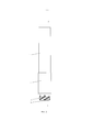
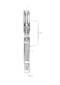
[0028] ФИГ. 2 - вид спереди всасывающей насадки электронной сигареты в соответствии с первым вариантом осуществления настоящего изобретения.FIG. 2 is a front view of an electronic cigarette suction nozzle according to a first embodiment of the present invention.
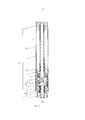
[0029] ФИГ. 3 - вид ФИГ. 2 в разрезе по линии А-А.FIG. 3 is a view of FIG. 2 in a section along the line AA.
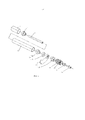
[0030] ФИГ. 4 - изображение в разобранном виде всасывающей насадки электронной сигареты в соответствии с первым вариантом осуществления настоящего изобретения.FIG. 4 is an exploded view of the suction nozzle of an electronic cigarette in accordance with a first embodiment of the present invention.
[0031] ФИГ. 5 - вид в разрезе первого электродного элемента всасывающей насадки электронной сигареты в соответствии с первым вариантом осуществления настоящего изобретения.FIG. 5 is a cross-sectional view of a first electrode element of an electronic cigarette suction nozzle according to a first embodiment of the present invention.
[0032] ФИГ. 6 - вид в перспективе распыляющего стакана всасывающей насадки электронной сигареты в соответствии с первым вариантом осуществления настоящего изобретения.FIG. 6 is a perspective view of a spray cup of an electronic cigarette suction nozzle according to a first embodiment of the present invention.
[0033] ФИГ. 7 - вид в разрезе распыляющего стакана всасывающей насадки электронной сигареты в соответствии с первым вариантом осуществления настоящего изобретения.FIG. 7 is a cross-sectional view of a spray cup of a suction nozzle of an electronic cigarette in accordance with a first embodiment of the present invention.
[0034] ФИГ. 8 - вид в перспективе резервуара всасывающей насадки электронной сигареты в соответствии с первым вариантом осуществления настоящего изобретения.FIG. 8 is a perspective view of an e-cigarette suction nozzle reservoir in accordance with a first embodiment of the present invention.
[0035] ФИГ. 9 - вид в перспективе основания для отделения жидкости всасывающей насадки электронной сигареты в соответствии с первым вариантом осуществления настоящего изобретения.FIG. 9 is a perspective view of a base for separating a liquid of a suction nozzle of an electronic cigarette in accordance with a first embodiment of the present invention.
[0036] ФИГ. 10 - вид в разрезе основания для отделения жидкости всасывающей насадки электронной сигареты в соответствии с первым вариантом осуществления настоящего изобретения.FIG. 10 is a cross-sectional view of a base for separating a liquid of a suction nozzle of an electronic cigarette in accordance with a first embodiment of the present invention.
[0037] ФИГ. 11 - вид в перспективе крышки всасывающего сопла всасывающей насадки электронной сигареты в соответствии с первым вариантом осуществления настоящего изобретения.FIG. 11 is a perspective view of a cap of a suction nozzle of an electronic cigarette suction nozzle according to a first embodiment of the present invention.
[0038] ФИГ. 12 - вид в разрезе крышки сопла всасывающей насадки электронной сигареты в соответствии с первым вариантом осуществления настоящего изобретения.FIG. 12 is a cross-sectional view of a nozzle cap of an electronic cigarette suction nozzle according to a first embodiment of the present invention.
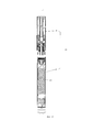
[0039] ФИГ. 13 - вид в разрезе электронной сигареты, в которой использована всасывающая насадка электронной сигареты в соответствии с первым вариантом осуществления настоящего изобретения.FIG. 13 is a sectional view of an electronic cigarette using an electronic cigarette suction nozzle according to a first embodiment of the present invention.
[0040] ФИГ. 14 - вид в разрезе всасывающей насадки электронной сигареты в соответствии со вторым вариантом осуществления настоящего изобретения.FIG. 14 is a cross-sectional view of an electronic cigarette suction nozzle according to a second embodiment of the present invention.
[0041] ФИГ. 15 - вид в разрезе электронной сигареты, в которой использована всасывающая насадка электронной сигареты в соответствии со вторым вариантом осуществления настоящего изобретения.FIG. 15 is a cross-sectional view of an electronic cigarette using an electronic cigarette suction nozzle according to a second embodiment of the present invention.
ПОДРОБНОЕ ОПИСАНИЕ ВАРИАНТОВ ОСУЩЕСТВЛЕНИЯDETAILED DESCRIPTION OF EMBODIMENTS
[0042] Как показано на фигурах с 1 по 13, предложена электронная сигарета 100, в соответствии с первым вариантом осуществления настоящего изобретения. Электронная сигарета 100 содержит всасывающую насадку 90 электронной сигареты и силовой стержень 91. Всасывающая насадка 90 электронной сигареты и силовой стержень 91 соединены крепежными средствами, заглушками, винтовой резьбой и т.п., при этом в данном варианте осуществления использована винтовая резьба.[0042] As shown in figures 1 to 13, proposed
[0043] Всасывающая насадка 90 электронной сигареты содержит всасывающий цилиндр 1, распыляющее устройство 2, блок направления жидкости 3, включающий основание для отделения жидкости 31 и корпус для хранения жидкости 32, крышку всасывающего сопла 4, направляющую трубку 5 и декоративную гильзу 6.[0043] The
[0044] Всасывающий цилиндр 1 служит для установки распыляющего устройства 2, блока направления жидкости 3, крышки сопла 4 и направляющей трубки 5. Всасывающий цилиндр 1 имеет полую трубчатую форму, в данном варианте осуществления он представляет собой цилиндрическую оболочку и получен отрезкой прозрачной или полупрозрачной удлиненной трубки, при этом нужную длину всасывающего цилиндра 1 можно получить отрезкой удлиненной трубки в соответствии с фактическими требованиями. Всасывающий цилиндр 1 содержит наконечник и соединительный конец, при этом крышка сопла 4 накрывает наконечник, чтобы облегчить пользователю затяжку, а соединительный конец контактирует с силовым стержнем 91.[0044] The
[0045] Всасывающий цилиндр 1 дополнительно снабжен резервуаром для сигаретной жидкости 11, предназначенным для хранения жидкого дыма, и соединительным узлом 12 для соединения с силовым стержнем 92. Соединительный узел 12 содержит первый электродный элемент 13, служащий первым электродом (например, отрицательным электродом) распыляющего устройства 2, второй электродный элемент 14, расположенный в первом электродном элементе 13 и служащий вторым электродом (например, положительным электродом), и изолирующее кольцо 15. Резервуар для сигаретной жидкости 11 предусмотрен во всасывающем цилиндре 1, при этом в данном варианте осуществления резервуар для сигаретной жидкости 11 совместно образован основанием для отделения жидкости 31, крышкой сопла 4, внутренней стенкой всасывающего цилиндра 1 и наружной стенкой направляющей трубки, при этом основание для отделения жидкости 31 и крышка сопла 4 уплотняют противоположные концы резервуара с сигаретной жидкостью 11 для герметизации жидкого дыма в резервуаре для сигаретной жидкости 11. Первый электродный элемент 13 расположен у соединительного конца всасывающего цилиндра 1. В данном варианте осуществления первый электродный элемент 13 представляет собой цилиндр и содержит первый конец 130, на котором выполнена наружная резьба для резьбового взаимодействия с силовым стержнем 91 электронной сигареты, и второй конец 132, вставленный во всасывающий цилиндр 1 через соединительный конец всасывающего цилиндра 1 и неподвижно охватываемый во всасывающем цилиндре 1. Второй конец 132 образует принимающую камеру для размещения и закрепления распыляющего устройства 2. Между первым концом 130 и вторым концом 132 предусмотрен фланец 134 для уплотнения соединительного конца всасывающего цилиндра 1, при этом первый конец 130 дополнительно образует входное отверстие 131 для входа атмосферного воздуха во всасывающий цилиндр 1. Второй конец 132 первого электродного элемента 13 расположен в распыляющем устройстве 2, второй электродный элемент 14 установлен в первом конце 130, при этом, первый электродный элемент 13 сам по себе служит отрицательным электродом распыляющего устройства 2 для электрического соединения с отрицательным электродом внутри силового стержня 91. Форма второго электродного элемента 14 подогнана к форме первого конца первого электродного элемента 13, при этом он зафиксирован и изолирован изолирующим кольцом 15, которое зажато между первым электродным элементом 13 и вторым электродным элементом 14. Торцевая сторона второго электродного элемента 14 используется для упора в соответствующий электрод силового стержня 91 для обеспечения проводимости. Всасывающий цилиндр 1 выполнен в виде полностью прозрачной оболочки или, по меньшей мере, частично прозрачной, или, по меньшей мере, его часть, где находится резервуар для сигаретной жидкости 11, выполнена прозрачной, чтобы облегчить наблюдение за объемом жидкого дыма в резервуаре с сигаретной жидкостью 11.[0045] The
[0046] Распыляющее устройство 2 содержит распылитель 21 и распыляющий стакан 22. Распылитель 21 содержит нагревательную проволоку 211 и волокнистый элемент 212 для адсорбции жидкого дыма и поддержания нагревательной проволоки 211. Нагревательная проволока 211 намотана на волокнистый элемент 412, и неподвижно размещена внутри распыляющего стакана 22 посредством волокнистого элемента 212. Волокнистый элемент 212 служит для абсорбирования жидкого дыма и просачивания жидкого дыма рядом с нагревательной проволокой 211 для преобразования жидкого дыма в дым в виде тумана, он выполнен из стекловолокна в форме бечевки или в форме столбика. В данном варианте осуществления, волокнистый элемент 212 имеет U-образную форму, при этом его противоположные концы упираются в блок направления жидкости 3 для облегчения просачивания жидкого дыма из блока направления жидкости 3.[0046] The
[0047] Распыляющий стакан 22 (см. ФИГ. 6 и ФИГ. 7) представляет собой чашку, выполненную за одно целое прессованием, и содержит нижнюю стенку и кольцевую боковую стенку (помечена) и распыляющую камеру 221, образованную нижней стенкой и кольцевой боковой стенкой, установочное седло 222 с фиксирующей прорезью, два перфорационных отверстия 223, отверстие для рассеивания тепла 224, расположенное у центрального участка распыляющего колпачка 22 и проходящее через него. Распыляющая камера представляет собой прямоугольную прорезь и расположена поперек фиксирующей прорези установочного седла 222 для обеспечения вентиляции. Установочное седло 222 с фиксирующей прорезью вдавлено внутрь на определенную глубину от верхней поверхности распыляющего стакана 22, чтобы образовать углубление для размещения распылителя 21, при этом волокнистый элемент 212 зафиксирован и установлен в фиксирующей прорези утановочного седла 222 для незатруднительной установки. Перфорационные отверстия 223 служат для вставки нагревательной проволоки 211, при этом перфорационные отверстия 223 проходят через оба конца распыляющего стакана 22 и сообщены с распыляющей камерой 221. В данном варианте осуществления, предусмотрено два перфорационных отверстия 223, при этом нагревательная проволока 211 намотана вокруг волокнистого элемента 212, причем один ее конец проходит через соответствующее перфорационное отверстие 223, а затем проходит по нижней стенке распыляющего стакана 22, после сгиба, и электрически подсоединен к первому электродному элементу 13 после повторного сгиба. Упомянутый один конец нагревательной проволоки плотно зажат между внутренней стенкой первого электродного элемента 13 и наружной стенкой распыляющего стакана 22 за счет взаимного расширения распыляющего стакана 22 и первого электродного элемента 13 для получения электрического подсоединения с первым электродным элементом 13. Другой конец нагревательной проволоки 211 проходит через другое перфорационное отверстие 223 и электрически связан со вторым электродным элементом 14, при этом он плотно зажат между наружной стенкой второго электродного элемента 14 и внутренней стенкой изолирующего кольца 15 за счет взаимного расширения изолирующего кольца 15 и второго электродного элемента 14. Способ зажатия реализует электрическую связь путем простого процесса, обеспечивая простоту установки без использования сварки. Рассеивающее тепло отверстие 224 предназначено для вентиляции и обеспечивает возможность передачи тепла, созданного распылителем 21, к силовому стержню 91. Нижний конец распыляющего устройства 22 и внутренняя стенка второго конца 132 первого электродного элемента 13 совместно задействованы для затяжки нагревательной проволоки 211. В данном варианте осуществления, для распыляющего стакана 22 выбран материал, обладающий хорошей теплостойкостью, такой как силикон, для достижения лучшего эффекта тепловой изоляции распыляющего стакана 22. Распыляющий стакан 22 в данном варианте осуществления упрощает процесс изготовления всасывающей насадки электронной сигареты, а также - упрощает установку распылителя 21. Более того, поскольку распыляющий стакан 22 выполнен из силикона, обладающего хорошей теплостойкостью, он обеспечивает лучший эффект тепловой изоляции, в соответствии с чем наружная стенка всасывающего сопла при использовании имеет низкую температуру и не вызывает ожога руки или рта пользователя.[0047] The spray cup 22 (see FIG. 6 and FIG. 7) is a cup made in one piece by pressing, and comprises a bottom wall and an annular side wall (marked) and a
[0048] Блок направления жидкости 3 служит для направления жидкого дыма, находящегося в резервуаре для сигаретной жидкости 11, в распыляющий стакан 22 для распыления и содержит основание для отделения жидкости 31 и корпус для хранения жидкости 32. Жидкий дым в резервуаре для сигаретной жидкости 11 просачивается через основание для отделения жидкости 31, абсорбируется и хранится в корпусе для хранения жидкости 32 для распыления. Основание для отделения жидкости 31 (см. ФИГ. 9 и ФИГ. 10) содержит дренажную трубку 312 и седло 310, охватывающее дренажную трубку 312, и выполнено из силикона. В центре дренажной трубки 312 выполнено сквозное отверстие 313. Седло 310 образует отверстия для направления жидкости 311, при этом объем потока жидкого дыма зависит от размера и числа отверстий для направления жидкости 311. Обращаясь к направлениям, как показано на ФИГ. 10, седло 310 содержит верхнюю поверхность 3101 и нижнюю поверхность 3102 и плотно упирается в торец резервуара для сигаретной жидкости 11 внутри всасывающего цилиндра 1, чтобы герметизировать жидкий дым, верхняя поверхность 3101 обращена к резервуару для сигаретной жидкости 11. Дренажная трубка 312, соответствующим образом, имеет верхний конец и нижний конец, и, соответственно, сообщается с направляющей трубкой 5 и распыляющей камерой 221, чтобы обеспечить поток дыма и воздуха. Жидкий дым распыляется распылителем 21 и становится дымом в виде тумана, который проходит посредством дренажной трубки 312 из распыляющей камеры 221 к направляющей трубке, чтобы попасть к наружному пространству всасывающего цилиндра 1 или для затяжки пользователем.[0048] The
[0049] В одном варианте осуществления сквозное отверстие 313 проходит через верхний конец и нижний конец дренажной трубки 312 и образует внутреннюю кромку 3120 на ее внутренней стенке. Один конец направляющей трубки 5 вставлен в сквозное отверстие 313 путем расширения и последующего упора во внутреннюю кромку 3120, чтобы зафиксировать упомянутый конец направляющей трубки 5 в дренажной трубке 312.[0049] In one embodiment, the through
[0050] Предпочтительно, дренажная трубка 312 и седло 310 оба выполнены, по существу, цилиндрическими, коаксиальны друг другу и имеют поперечный профиль. Дренажная трубка 312 расположена в центре седла 310, при этом ее противоположные концы вытянуты в осевом направлении. Седло 310 основания для отделения жидкости 31 содержит кольцевую стенку с диаметром, превышающим диаметр дренажной трубки 312, и высотой, меньшей высоты дренажной трубки 312. Сквозное отверстие 313 представляет собой осевое отверстие, при этом отверстия для направления жидкости 311 проходят через кольцевую стенку седла 310 в направлении, параллельном оси седла. Предпочтительно, дренажная трубка 312 и седло 310 выполнены за одно целое.[0050] Preferably, the
[0051] Корпус для хранения жидкости 32 служит для абсорбирования жидкого дыма, просочившегося из основания для отделения жидкости 31, и выполнен из хлопкового материала, стойкого к высоким температурам, хлопка со стекловолокном или толстой хлопковой ткани, способной абсорбировать воду и сохранять ее, подобно губке, таким образом, жидкий дым может медленно просачиваться в распыляющий стакан 22. Корпус для хранения жидкости 32 и основание для отделения жидкости 31 подогнаны друг к другу по форме, при этом верхняя поверхность корпуса для хранения жидкости 32 прикреплена к нижней поверхности 3102 основания для отделения жидкости 310, чтобы абсорбировать жидкий дым, вытекающий из отверстия для направления жидкости 311. Корпус для хранения жидкости 32 имеет нижнюю поверхность, прикрепленную к торцу распыляющего стакана 22, где расположен распылитель, при этом противоположные концы волокнистого элемента 212 упираются в нижнюю поверхность корпуса для хранения жидкости 32,чтобы адсорбировать жидкий дым в корпусе для хранения жидкости 32, для облегчения распыления жидкого дыма нагревательной проволокой 211. В релевантных вариантах осуществления, корпус для хранения жидкости 32 представляет собой цилиндр с таким же наружным диаметром, как и наружный диаметр основания для отделения жидкости 31, и образует в центре гильзовое отверстие 321, при этом корпус для хранения жидкости 32 охватывает наружную стенку нижнего конца дренажной трубки 312 посредством гильзового отверстия 321. Корпус для хранения жидкости 32 может интерференционно взаимодействовать с наружной стенкой дренажной трубки 312. Блок направления жидкости 3 обеспечивает удобство сборки всасывающей насадки электронной сигареты 90, с обеспечением хорошего дренажного эффекта, и может предотвратить утечку жидкого дыма из резервуара для сигаретной жидкости 11.[0051] A
[0052] Крышка сопла 4 вставлена в оконечный торец всасывающего цилиндра 1, и выполнена из силикона, для герметизации жидкого дыма, фиксации направляющей трубки 5 и для вентиляции. В ее центральной части имеется сквозное отверстие 41 (см. ФИГ. 11 и ФИГ. 12), в которое вставлена направляющая трубка 5, сквозное отверстие 41 представляет собой прямые отверстия или ступенчатое отверстие, проходящее через верхний и нижний торцы крышки сопла 4. В данном варианте осуществления, крышка сопла 4 представляет собой ступенчатый цилиндр и содержит увеличенный хомут 42 с большим наружным диаметром и внутренним цилиндром 40, проходящим в осевом направлении от расширенного хомута 42 и имеющим меньший наружный диаметр, при этом сквозное отверстие 41 проходит в осевом направлении через внутренний цилиндр 40 и расширенный хомут 42. Внутренний цилиндр установлен на конце направляющей трубки 5, противоположном блоку направления жидкости 3, чтобы закрепить направляющую трубку 5; расширенный хомут 42 введен в контакт с оконечным торцом всасывающего цилиндра 1 путем расширения и герметизирует торец резервуара для сигаретной жидкости 11. Сквозное отверстие 41 сообщено с направляющей трубкой 5, образуя проходной канал для дыма.[0052] The
[0053] Направляющая трубка 5 представляет собой проходной канал для дыма, преобразованного в туман при распылении жидкого дыма распыляющим устройством 2, ведущий наружу всасывающего цилиндра. В данном варианте осуществления, направляющую трубку 5 получают отрезкой цилиндрической металлической или пластмассовой трубки, при этом нужная длина направляющей трубки 5 может быть получена отрезкой в соответствии с фактическими требованиями. Направляющая трубка 5 находится внутри всасывающего цилиндра 1, при этом один ее конец вставлен в крышку сопла 4 и сообщен с наружным пространством всасывающего цилиндра 1, а другой ее конец вставлен в основание для отделения жидкости 31 и сообщен с распыляющей камерой 221. Соединение направляющей трубки 5 и крышки сопла 4 герметизировано по периферии, и соединение направляющей трубки 5 и основания для отделения жидкости 31 также герметизировано по периферии. Направляющая трубка 5 расположена внутри всасывающего цилиндра 1, причем, предпочтительно, по центральной линии, такая конструкция может обеспечить меньший объем всасывающей насадки электронной сигареты 90 в случае обеспечения предварительно заданного резервируемого объема жидкого дыма.[0053] The
[0054] Поскольку длина направляющей трубки и всасывающего цилиндра 1 могут быть получены отрезкой соответствующих трубок, согласно имеющимся фактическим требованиям, длину всасывающей насадки 90 и резервируемый объем жидкого дыма можно регулировать в соответствии с длинами всасывающего цилиндра 1 и направляющей трубки 5.[0054] Since the length of the guide tube and the
[0055] Декоративная втулка 6 имеет цилиндрическую форму и охватывает конец наружной стенки всасывающего цилиндра 1, противоположный крышке сопла 4, выполняя декоративную функцию, или служит для нанесения торговой марки на всасывающую насадку 90 электронной сигареты.[0055] The
[0056] Для всасывающей насадки 90 электронной сигареты по первому варианту осуществления жидкий дым заранее инжектируется в резервуар для сигаретной жидкости 11, при этом когда крышку сопла 4 устанавливают и без возможности съема закрепляют во всасывающем цилиндре, жидкий дым нельзя снова добавить в резервуар для сигаретной жидкости 11 после того, как жидкий дым закончится. Всасывающая насадка 90 электронной сигареты является одноразовой.[0056] For the electronic
[0057] Силовой стержень 91 содержит аккумуляторную батарею 911 и соответствующие электроды. Перед началом работы электронной сигареты небольшое количество жидкого дыма подается из резервуара для сигаретной жидкости 11 через блок направления жидкости 3 и накапливается в волокнистом элементе 212. Во время работы устройства при нажатии на кнопку (не показана) электронной сигареты 100, чтобы включить ее, приводится в действие нагревательная проволока 211 распыляющего устройства 2, создающая тепло, при этом жидкий дым, находящийся в волокнистом элементе 212, нагревается и преобразуется в дым в виде тумана, этот дым в виде тумана в распыляющей камере 221 попадает в направляющую трубку 5 через дренажную трубку 312 блока направления жидкости, а затем проходит через сквозное отверстие 41 крышки сопла 4 для его вдыхания.[0057] The
[0058] Как показано на ФИГ. 14, в соответствии со вторым вариантом осуществления настоящего изобретения, предложена еще одна всасывающая насадка электронной сигареты 90', сходная по конфигурации с всасывающей насадкой 90 электронной сигареты. Различие между ними заключается в следующем: крышка сопла 4' дополнительно снабжена установочной гильзой 7 для установки направляющей трубки 5, крышка сопла 4' и установочная гильза 7 выполнены обе из силикона, при этом крышка сопла 4' имеет, по существу, цилиндрическую форму, причем в крышке сопла 4' имеется проходящее в аксиальном направлении сквозное отверстие 41' и вставной штырь 42'. Установочная гильза 7 является, по существу, цилиндрической и образует установочное отверстие 71, проходящее в осевом направлении для установки направляющей трубки 5, и отверстие для инжекции 72, через которое осуществляется инжекция жидкого дыма во всасывающий цилиндр 1. Установочное отверстие 71 сообщено со сквозным отверстием 41', вставной штырь 42' может быть вставлен в инжекционное отверстие 72. Направляющая трубка 5 вставлена в установочное отверстие 71 и сообщена со сквозным отверстием 41' крышки сопла 4' через установочное отверстие 71. Установочная гильза 7 закреплена в торце всасывающего цилиндра 1, где расположена крышка сопла 4', при этом место соединения установочной гильзы и всасывающего цилиндра 1, предпочтительно, герметизировано. После того как жидкий дым инжектирован во всасывающий цилиндр 1 через инжекционное отверстие 72, крышку сопла 4' устанавливают во всасывающий цилиндр 1, герметизируя жидкий дым во всасывающем цилиндре вставным штырем 42', вставленным в инжекционное отверстие 72. Крышка сопла 4' подвижно установлена во всасывающем цилиндре 1, при этом ее можно извлечь из всасывающего цилиндра 1 после того, как закончится жидкий дым, и его можно инжектировать во всасывающий цилиндр снова, через инжекционное отверстие 72, для дальнейшего использования устройства. Таким образом, всасывающая насадка 90' электронной сигареты может быть многократно использована.[0058] As shown in FIG. 14, in accordance with a second embodiment of the present invention, there is provided another suction nozzle of an electronic cigarette 90 ', similar in configuration to the
[0059] Как показано на ФИГ. 15, электронная сигарета 200, в которой применяется всасывающая насадка электронной сигареты 90', далее представлена во втором варианте осуществления настоящего изобретения и приводится в действие силовым стержнем 91. Силовой стержень 91 подсоединен к всасывающей насадке 90' электронной сигареты. Поскольку всасывающая насадка 90' электронной сигареты может быть многократно использована, в соответствии с этим электронная сигарета 200 также является устройством многократного применения.[0059] As shown in FIG. 15, an
[0060] Выше описаны только варианты осуществления настоящего изобретения. Следует отметить, что специалистам обычного уровня в этой области понятно, что возможны усовершенствования и модификации в рамках существа настоящего изобретения, при этом данные усовершенствования и модификации считаются включенными в заявленный объем этого изобретения.[0060] Only embodiments of the present invention are described above. It should be noted that it will be understood by those of ordinary skill in the art that improvements and modifications are possible within the spirit of the present invention, while these improvements and modifications are considered to be included in the claimed scope of this invention.
Claims (11)
всасывающий цилиндр (1),
направляющую трубку (5),
резервуар (11) для сигаретной жидкости,
блок (3) направления жидкости со сквозным отверстием в нем,
крышку (4) всасывающего сопла со сквозным отверстием в ней,
распыляющее устройство (2) и
соединительный узел (12),
в которой
крышка (4) сопла и соединительный узел (12) соответственно вставлены с противоположных концов во всасывающий цилиндр (1);
направляющая трубка (5), блок (3) направления жидкости, распыляющее устройство (2) и резервуар (11) с сигаретной жидкостью расположены во всасывающем цилиндре (1),
крышка (4) сопла и блок (3) направления жидкости соответственно герметизируют противоположные концы резервуара (11) с сигаретной жидкостью;
направляющая трубка (5) находится в резервуаре (11) для сигаретной жидкости, причем ее противоположные концы соответственно вставлены в сквозное отверстие крышки (4) сопла и в сквозное отверстие блока (3) направления жидкости так, что крышка (4) сопла, блок (3) направления жидкости и направляющая трубка (5) образуют канал для прохода дыма, при этом противоположные концы канала для прохода дыма соответственно сообщены с наружным пространством крышки (4) сопла и распыляющим устройством (2),
распыляющее устройство (2) расположено между блоком (3) направления жидкости и соединительным узлом (12),
блок (3) направления жидкости содержит совместно закрепленные основание (13) для отделения жидкости и корпус (32) для хранения жидкости,
основание (31) для отделения жидкости содержит седло (310) и дренажную трубку (312), проходящую через центр седла (310) в противоположных направлениях по длине седла (310), при этом в дренажной трубке (312) имеется сквозное отверстие блока (3) направления жидкости; один конец дренажной трубки (312) контактирует с направляющей трубкой (5), а другой конец дренажной трубки (312) охватывает корпус (32) для хранения жидкости и сообщен с распыляющим устройством (2),
основание (31) для отделения жидкости образует по меньшей мере одно отверстие (311) для направления жидкости, при этом жидкий дым в резервуаре (11) для сигаретной жидкости просачивается по меньшей мере через одно отверстие (311) для направления жидкости, абсорбируется и накапливается в корпусе (32) для хранения жидкости с целью его распыления в распыляющем устройстве (2),
распыляющее устройство (2) содержит распылитель (21) для преобразования жидкого дыма в дым в виде тумана, а также распыляющий стакан (22) для размещения в нем распылителя (21), при этом распылитель содержит нагревательную проволоку (211) для распыления жидкого дыма и волокнистый элемент (212) для абсорбирования жидкого дыма и поддержания нагревательной проволоки (211), при этом волокнистый элемент (212) упирается в корпус (32) для хранения жидкости для абсорбирования жидкого дыма, предназначенного для распыления.1. A suction nozzle (90) for an electronic cigarette (100) containing
suction cylinder (1),
guide tube (5),
reservoir (11) for cigarette liquid,
block (3) the direction of the liquid with a through hole in it,
the cover (4) of the suction nozzle with a through hole in it,
a spray device (2) and
connection unit (12),
wherein
the nozzle cap (4) and the connecting unit (12) are respectively inserted from opposite ends into the suction cylinder (1);
a guide tube (5), a liquid direction block (3), a spray device (2) and a cigarette liquid reservoir (11) are located in the suction cylinder (1),
the nozzle cap (4) and the liquid guiding unit (3) respectively seal the opposite ends of the tank (11) with the cigarette liquid;
the guide tube (5) is located in the reservoir (11) for the cigarette liquid, and its opposite ends are respectively inserted into the through hole of the nozzle cover (4) and into the through hole of the fluid guide unit (3) so that the nozzle cover (4), the unit ( 3) the directions of the liquid and the guide tube (5) form a channel for the passage of smoke, while the opposite ends of the channel for the passage of smoke respectively communicate with the outer space of the cap (4) of the nozzle and the spray device (2),
a spray device (2) is located between the block (3) of the direction of the liquid and the connecting node (12),
the liquid direction block (3) contains a jointly fixed base (13) for separating the liquid and a housing (32) for storing the liquid,
the base (31) for separating the liquid contains a saddle (310) and a drainage tube (312) passing through the center of the saddle (310) in opposite directions along the length of the saddle (310), while in the drainage tube (312) there is a through hole of the block (3 ) fluid direction; one end of the drainage tube (312) is in contact with the guide tube (5), and the other end of the drainage tube (312) covers the housing (32) for storing liquid and is in communication with the spray device (2),
the liquid separation base (31) forms at least one hole (311) for guiding the liquid, while liquid smoke in the cigarette liquid reservoir (11) seeps through at least one liquid guiding hole (311), is absorbed and accumulates in a housing (32) for storing liquid in order to spray it in a spray device (2),
the spray device (2) contains a spray (21) for converting liquid smoke into smoke in the form of a mist, and also a spray cup (22) for accommodating a spray therein (21), wherein the spray includes a heating wire (211) for spraying liquid smoke and a fibrous element (212) for absorbing liquid smoke and maintaining the heating wire (211), while the fibrous element (212) abuts against the housing (32) for storing liquid for absorbing liquid smoke for spraying.
распыляющий стакан (22) представляет собой цилиндрическую чашку, выполненную за одно целое с помощью формования, и содержит установочное седло (222) для установки волокнистого элемента (212), рассеивающее тепло отверстие (224) для вентиляции и рассеивания тепла и пару перфорационных отверстий (223) для вставки противоположных концов нагревательной проволоки (211).5. The suction nozzle for an electronic cigarette according to claim 1, in which
the spray cup (22) is a cylindrical cup made in one piece by molding, and contains an installation seat (222) for installing the fiber element (212), a heat-dissipating hole (224) for ventilation and heat dissipation, and a pair of perforation holes (223 ) to insert the opposite ends of the heating wire (211).
всасывающий цилиндр (1),
направляющую трубку (5),
резервуар (11) для сигаретной жидкости,
блок (3) направления жидкости со сквозным отверстием в нем,
крышку (4) всасывающего сопла со сквозным отверстием в ней,
распыляющее устройство (2) и
соединительный узел (12),
в которой
крышка (4) сопла и соединительный узел (12) соответственно вставлены с противоположных концов во всасывающий цилиндр (1);
направляющая трубка (5), блок (3) направления жидкости, распыляющее устройство (2) и резервуар (11) с сигаретной жидкостью расположены во всасывающем цилиндре (1);
крышка (4) сопла и блок (3) направления жидкости соответственно герметизируют противоположные концы резервуара (11) с сигаретной жидкостью;
направляющая трубка (5) находится в резервуаре (11) для сигаретной жидкости, причем ее противоположные концы соответственно вставлены в сквозное отверстие крышки (4) сопла и в сквозное отверстие блока (3) направления жидкости так, что крышка (4) сопла, блок (3) направления жидкости и направляющая трубка (5) образуют канал для прохода дыма, при этом противоположные концы канала для прохода дыма соответственно сообщены с наружным пространством крышки (4) сопла и распыляющим устройством (2);
распыляющее устройство (2) расположено между блоком (3) направления жидкости и соединительным узлом (12),
блок (3) направления жидкости содержит совместно закрепленные основание (13) для отделения жидкости и корпус (32) для хранения жидкости,
основание (31) для отделения жидкости содержит седло (310) и дренажную трубку (312), проходящую через центр седла (310) в противоположных направлениях по длине седла (310), при этом в дренажной трубке (312) имеется сквозное отверстие блока (3) направления жидкости; один конец дренажной трубки (312) контактирует с направляющей трубкой (5), а другой конец дренажной трубки (312) охватывает корпус (32) для хранения жидкости и сообщен с распыляющим устройством (2),
основание (31) для отделения жидкости образует по меньшей мере одно отверстие (311) для направления жидкости, при этом жидкий дым в резервуаре (11) для сигаретной жидкости просачивается по меньшей мере через одно отверстие (311) для направления жидкости, абсорбируется и накапливается в корпусе (32) для хранения жидкости с целью его распыления в распыляющем устройстве (2),
крышка (4) сопла представляет собой цилиндр ступенчатой формы и содержит расширенный хомут (42) с большим наружным диаметром и внутренний цилиндр (40), проходящий в осевом направлении от расширенного хомута (42) и имеющий меньший наружный диаметр, при этом сквозное отверстие крышки (4) сопла проходит в осевом направлении через внутренний цилиндр (4) и расширенный хомут (42), внутренний цилиндр (40) установлен на наружной стенке конца направляющей трубки (5) для закрепления направляющей трубки, расширенный хомут (42) взаимодействует с оконечностью торца всасывающего цилиндра (1) путем расширения и герметизирует торец резервуара (11) для сигаретной жидкости,
направляющая трубка (5) сообщена со сквозным отверстием крышки (4) сопла через установочную гильзу (7), установочная гильза закреплена во всасывающем цилиндре (1) и присоединена к крышке (4) сопла, в установочной гильзе (7) выполнено установочное отверстие, в которое вставлена направляющая трубка (5), при этом крышка (4) сопла сообщена с инжекционным отверстием (72) для инжекции жидкого дыма в резервуар (11) для сигаретной жидкости соответственно, крышка (4) сопла образует вставной штырь (42) для его вставки в инжекционное отверстие (72) с целью герметизации резервуара (11) для сигаретной жидкости.6. A suction nozzle (90) for an electronic cigarette (100), comprising
suction cylinder (1),
guide tube (5),
reservoir (11) for cigarette liquid,
block (3) the direction of the liquid with a through hole in it,
the cover (4) of the suction nozzle with a through hole in it,
a spray device (2) and
connection unit (12),
wherein
the nozzle cap (4) and the connecting unit (12) are respectively inserted from opposite ends into the suction cylinder (1);
a guide tube (5), a liquid direction block (3), a spray device (2) and a cigarette liquid reservoir (11) are located in the suction cylinder (1);
the nozzle cap (4) and the liquid guiding unit (3) respectively seal the opposite ends of the tank (11) with the cigarette liquid;
the guide tube (5) is located in the reservoir (11) for the cigarette liquid, and its opposite ends are respectively inserted into the through hole of the nozzle cover (4) and into the through hole of the fluid guide unit (3) so that the nozzle cover (4), the unit ( 3) the directions of the liquid and the guide tube (5) form a channel for the passage of smoke, while the opposite ends of the channel for the passage of smoke respectively communicate with the outer space of the cap (4) of the nozzle and the spray device (2);
a spray device (2) is located between the block (3) of the direction of the liquid and the connecting node (12),
the liquid direction block (3) contains a jointly fixed base (13) for separating the liquid and a housing (32) for storing the liquid,
the base (31) for separating the liquid contains a saddle (310) and a drainage tube (312) passing through the center of the saddle (310) in opposite directions along the length of the saddle (310), while in the drainage tube (312) there is a through hole of the block (3 ) fluid direction; one end of the drainage tube (312) is in contact with the guide tube (5), and the other end of the drainage tube (312) covers the housing (32) for storing liquid and is in communication with the spray device (2),
the liquid separation base (31) forms at least one hole (311) for guiding the liquid, while liquid smoke in the cigarette liquid reservoir (11) seeps through at least one liquid guiding hole (311), is absorbed and accumulates in a housing (32) for storing liquid in order to spray it in a spray device (2),
the nozzle cap (4) is a stepped cylinder and contains an expanded clamp (42) with a large outer diameter and an inner cylinder (40) extending axially from the expanded clamp (42) and having a smaller outer diameter, with a through hole of the cap ( 4) the nozzle extends axially through the inner cylinder (4) and the expanded clamp (42), the inner cylinder (40) is mounted on the outer wall of the end of the guide tube (5) to secure the guide tube, the expanded clamp (42) interacts with the tip of the end and the suction cylinder (1) by expanding and sealing the end of the tank (11) for cigarette liquid,
the guide tube (5) is in communication with the through hole of the nozzle cover (4) through the installation sleeve (7), the installation sleeve is fixed in the suction cylinder (1) and attached to the nozzle cover (4), the installation hole is made in the installation sleeve, which the guide tube (5) is inserted, the nozzle cap (4) communicating with the injection hole (72) for injecting liquid smoke into the cigarette liquid reservoir (11), respectively, the nozzle cap (4) forms an insertion pin (42) for inserting it into the injection hole (72) to seal and a reservoir (11) for the cigarette liquid.
всасывающий цилиндр (1),
направляющую трубку (5),
резервуар (11) для сигаретной жидкости,
блок (3) направления жидкости со сквозным отверстием в нем,
крышку (4) всасывающего сопла со сквозным отверстием в ней,
распыляющее устройство (2) и
соединительный узел (12),
в которой
крышка (4) сопла и соединительный узел (12) соответственно вставлены с противоположных концов во всасывающий цилиндр (1);
направляющая трубка (5), блок (3) направления жидкости, распыляющее устройство (2) и резервуар (11) с сигаретной жидкостью расположены во всасывающем цилиндре (1);
крышка (4) сопла и блок (3) направления жидкости соответственно герметизируют противоположные концы резервуара (11) с сигаретной жидкостью;
направляющая трубка (5) находится в резервуаре (11) для сигаретной жидкости, причем ее противоположные концы соответственно вставлены в сквозное отверстие крышки (4) сопла и в сквозное отверстие блока (3) направления жидкости так, что крышка (4) сопла, блок (3) направления жидкости и направляющая трубка (5) образуют канал для прохода дыма, при этом противоположные концы канала для прохода дыма соответственно сообщены с наружным пространством крышки (4) сопла и распыляющим устройством (2);
распыляющее устройство (2) расположено между блоком (3) направления жидкости и соединительным узлом (12),
блок (3) направления жидкости содержит совместно закрепленные основание (13) для отделения жидкости и корпус (32) для хранения жидкости,
основание (31) для отделения жидкости содержит седло (310) и дренажную трубку (312), проходящую через центр седла (310) в противоположных направлениях по длине седла (310), при этом в дренажной трубке (312) имеется сквозное отверстие блока (3) направления жидкости; один конец дренажной трубки (312) контактирует с направляющей трубкой (5), а другой конец дренажной трубки (312) охватывает корпус (32) для хранения жидкости и сообщен с распыляющим устройством (2),
основание (31) для отделения жидкости образует по меньшей мере одно отверстие (311) для направления жидкости, при этом жидкий дым в резервуаре (11) для сигаретной жидкости просачивается по меньшей мере через одно отверстие (311) для направления жидкости, абсорбируется и накапливается в корпусе (32) для хранения жидкости с целью его распыления в распыляющем устройстве (2),
распыляющее устройство (2) содержит распылитель (21) для преобразования жидкого дыма в дым в виде тумана, а также распыляющий стакан (22) для размещения в нем распылителя (21), при этом распылитель содержит нагревательную проволоку (211) для распыления жидкого дыма и волокнистый элемент (212) для абсорбирования жидкого дыма и поддержания нагревательной проволоки (211), при этом волокнистый элемент (212) упирается в корпус (32) для хранения жидкости для абсорбирования жидкого дыма, предназначенного для распыления.
соединительный узел (12) содержит первый электродный элемент (13), один конец которого вставлен во всасывающий цилиндр (1) для закрепления распылительного устройства (2) во всасывающем цилиндре, второй электродный элемент (14) и изолирующее кольцо (15), расположенное между первым электродным элементом (13) и вторым электродным элементом (14), второй электродный элемент (14) закреплен в первом электродном элементе (13) через изолирующее кольцо (15),
один конец нагревательной проволоки (211) плотно зажат между наружной стенкой распыляющего стакана (22) и внутренней стенкой первого электродного элемента (13) для проводимости первого электрода, а ее другой конец плотно зажат между внутренней стенкой изолирующего кольца (15) и наружной стенкой второго электродного элемента (14) для обеспечения проводимости второго электрода;
распыляющий стакан (22) присоединен к корпусу (32) для хранения жидкости, распыляющий стакан (22) закреплен в первом электродном элементе (13).7. A suction nozzle (90) for an electronic cigarette (100) containing
suction cylinder (1),
guide tube (5),
reservoir (11) for cigarette liquid,
block (3) the direction of the liquid with a through hole in it,
the cover (4) of the suction nozzle with a through hole in it,
a spray device (2) and
connection unit (12),
wherein
the nozzle cap (4) and the connecting unit (12) are respectively inserted from opposite ends into the suction cylinder (1);
a guide tube (5), a liquid direction block (3), a spray device (2) and a cigarette liquid reservoir (11) are located in the suction cylinder (1);
the nozzle cap (4) and the liquid guiding unit (3) respectively seal the opposite ends of the tank (11) with the cigarette liquid;
the guide tube (5) is located in the reservoir (11) for the cigarette liquid, and its opposite ends are respectively inserted into the through hole of the nozzle cover (4) and into the through hole of the fluid guide unit (3) so that the nozzle cover (4), the unit ( 3) the directions of the liquid and the guide tube (5) form a channel for the passage of smoke, while the opposite ends of the channel for the passage of smoke respectively communicate with the outer space of the cap (4) of the nozzle and the spray device (2);
a spray device (2) is located between the block (3) of the direction of the liquid and the connecting node (12),
the liquid direction block (3) contains a jointly fixed base (13) for separating the liquid and a housing (32) for storing the liquid,
the base (31) for separating the liquid contains a saddle (310) and a drainage tube (312) passing through the center of the saddle (310) in opposite directions along the length of the saddle (310), while in the drainage tube (312) there is a through hole of the block (3 ) fluid direction; one end of the drainage tube (312) is in contact with the guide tube (5), and the other end of the drainage tube (312) covers the housing (32) for storing liquid and is in communication with the spray device (2),
the liquid separation base (31) forms at least one hole (311) for guiding the liquid, while liquid smoke in the cigarette liquid reservoir (11) seeps through at least one liquid guiding hole (311), is absorbed and accumulates in a housing (32) for storing liquid in order to spray it in a spray device (2),
the spray device (2) contains a spray (21) for converting liquid smoke into smoke in the form of a mist, and also a spray cup (22) for accommodating a spray therein (21), wherein the spray includes a heating wire (211) for spraying liquid smoke and a fibrous element (212) for absorbing liquid smoke and maintaining the heating wire (211), while the fibrous element (212) abuts against the housing (32) for storing liquid for absorbing liquid smoke for spraying.
the connecting unit (12) contains a first electrode element (13), one end of which is inserted into the suction cylinder (1) to secure the spray device (2) in the suction cylinder, a second electrode element (14) and an insulating ring (15) located between the first the electrode element (13) and the second electrode element (14), the second electrode element (14) is fixed in the first electrode element (13) through an insulating ring (15),
one end of the heating wire (211) is tightly clamped between the outer wall of the spray cup (22) and the inner wall of the first electrode element (13) for the conductivity of the first electrode, and its other end is tightly clamped between the inner wall of the insulating ring (15) and the outer wall of the second electrode element (14) to ensure the conductivity of the second electrode;
the spray cup (22) is attached to the housing (32) for storing liquid, the spray cup (22) is fixed in the first electrode element (13).
Applications Claiming Priority (1)
| Application Number | Priority Date | Filing Date | Title |
|---|---|---|---|
| PCT/CN2012/076493 WO2013181797A1 (en) | 2012-06-05 | 2012-06-05 | Electronic cigarette and suction rod thereof |
Publications (2)
| Publication Number | Publication Date |
|---|---|
| RU2014148908A RU2014148908A (en) | 2016-07-27 |
| RU2602964C2 true RU2602964C2 (en) | 2016-11-20 |
Family
ID=49668740
Family Applications (1)
| Application Number | Title | Priority Date | Filing Date |
|---|---|---|---|
| RU2014148908/12A RU2602964C2 (en) | 2012-06-05 | 2012-06-05 | Suction rod for electronic cigarette and electronic cigarette using said rod |
Country Status (9)
| Country | Link |
|---|---|
| US (1) | US9254007B2 (en) |
| EP (1) | EP2856892A4 (en) |
| JP (1) | JP5960352B2 (en) |
| KR (1) | KR101740108B1 (en) |
| CN (1) | CN104039182B (en) |
| AU (1) | AU2012381926B2 (en) |
| CA (1) | CA2875632C (en) |
| RU (1) | RU2602964C2 (en) |
| WO (1) | WO2013181797A1 (en) |
Cited By (8)
| Publication number | Priority date | Publication date | Assignee | Title |
|---|---|---|---|---|
| RU2729529C1 (en) * | 2017-01-13 | 2020-08-07 | Бритиш Америкэн Тобэкко (Инвестментс) Лимитед | Aerosol generation device and aerosol generation article |
| RU2745158C1 (en) * | 2017-10-24 | 2021-03-22 | Никовенчерс Трейдинг Лимитед | Electronic device for generating an aerosol |
| US11589617B2 (en) | 2017-01-05 | 2023-02-28 | Nicoventures Trading Limited | Aerosol generating device and article |
| RU2793312C2 (en) * | 2017-04-27 | 2023-03-31 | Раи Стретеджик Холдингс, Инк. | Aerosol delivery apparatus containing a ceramic wick element |
| US11623053B2 (en) | 2017-12-06 | 2023-04-11 | Nicoventures Trading Limited | Component for an aerosol-generating apparatus |
| US11653697B2 (en) | 2017-10-24 | 2023-05-23 | Nicoventures Trading Limited | Electronic aerosol provision device having chassis section and movable hatch section |
| US11849767B2 (en) | 2017-10-24 | 2023-12-26 | Nicoventures Trading Limited | Electronic aerosol provision device having chassis section and movable hatch section with sealed sleave |
| US11930851B2 (en) | 2017-10-24 | 2024-03-19 | Nicoventures Trading Limited | Electronic aerosol provision device having a chassis section and a movable hatch section with a sealed sleeve |
Families Citing this family (144)
| Publication number | Priority date | Publication date | Assignee | Title |
|---|---|---|---|---|
| US10244793B2 (en) | 2005-07-19 | 2019-04-02 | Juul Labs, Inc. | Devices for vaporization of a substance |
| US9861772B2 (en) | 2010-05-15 | 2018-01-09 | Rai Strategic Holdings, Inc. | Personal vaporizing inhaler cartridge |
| US10159278B2 (en) | 2010-05-15 | 2018-12-25 | Rai Strategic Holdings, Inc. | Assembly directed airflow |
| US9095175B2 (en) | 2010-05-15 | 2015-08-04 | R. J. Reynolds Tobacco Company | Data logging personal vaporizing inhaler |
| US9743691B2 (en) | 2010-05-15 | 2017-08-29 | Rai Strategic Holdings, Inc. | Vaporizer configuration, control, and reporting |
| US9259035B2 (en) | 2010-05-15 | 2016-02-16 | R. J. Reynolds Tobacco Company | Solderless personal vaporizing inhaler |
| US8757147B2 (en) | 2010-05-15 | 2014-06-24 | Minusa Holdings Llc | Personal vaporizing inhaler with internal light source |
| US10136672B2 (en) | 2010-05-15 | 2018-11-27 | Rai Strategic Holdings, Inc. | Solderless directly written heating elements |
| US9999250B2 (en) | 2010-05-15 | 2018-06-19 | Rai Strategic Holdings, Inc. | Vaporizer related systems, methods, and apparatus |
| US9078473B2 (en) | 2011-08-09 | 2015-07-14 | R.J. Reynolds Tobacco Company | Smoking articles and use thereof for yielding inhalation materials |
| CN202385728U (en) * | 2011-11-25 | 2012-08-22 | 周学武 | Electronic cigarette with built-in atomizer |
| US8881737B2 (en) | 2012-09-04 | 2014-11-11 | R.J. Reynolds Tobacco Company | Electronic smoking article comprising one or more microheaters |
| US8910639B2 (en) * | 2012-09-05 | 2014-12-16 | R. J. Reynolds Tobacco Company | Single-use connector and cartridge for a smoking article and related method |
| US10117460B2 (en) | 2012-10-08 | 2018-11-06 | Rai Strategic Holdings, Inc. | Electronic smoking article and associated method |
| US10034988B2 (en) | 2012-11-28 | 2018-07-31 | Fontem Holdings I B.V. | Methods and devices for compound delivery |
| US10031183B2 (en) | 2013-03-07 | 2018-07-24 | Rai Strategic Holdings, Inc. | Spent cartridge detection method and system for an electronic smoking article |
| US9220302B2 (en) | 2013-03-15 | 2015-12-29 | R.J. Reynolds Tobacco Company | Cartridge for an aerosol delivery device and method for assembling a cartridge for a smoking article |
| CN203329913U (en) * | 2013-05-07 | 2013-12-11 | 深圳市合元科技有限公司 | Electronic cigarette and atomizer with cotton |
| US20140355969A1 (en) * | 2013-05-28 | 2014-12-04 | Sis Resources, Ltd. | One-way valve for atomizer section in electronic cigarettes |
| CN203555161U (en) * | 2013-08-07 | 2014-04-23 | 深圳市合元科技有限公司 | Atomizer and electronic cigarette provided therewith |
| CN203482897U (en) * | 2013-08-22 | 2014-03-19 | 刘秋明 | Electronic cigarette |
| US10278422B2 (en) * | 2013-08-26 | 2019-05-07 | Altria Client Services Llc | Electronic cigarette with reduced energy consumption and environmental impact |
| US10194693B2 (en) | 2013-09-20 | 2019-02-05 | Fontem Holdings 1 B.V. | Aerosol generating device |
| US10980273B2 (en) | 2013-11-12 | 2021-04-20 | VMR Products, LLC | Vaporizer, charger and methods of use |
| CN203646506U (en) | 2013-12-09 | 2014-06-18 | 刘秋明 | Soft atomizer connector fixing structure and electronic cigarette |
| KR102130619B1 (en) | 2013-12-23 | 2020-07-07 | 쥴 랩스, 인크. | Vaporization device systems and methods |
| US10058129B2 (en) | 2013-12-23 | 2018-08-28 | Juul Labs, Inc. | Vaporization device systems and methods |
| USD803475S1 (en) * | 2014-01-31 | 2017-11-21 | Datamor Spörri-Treuhand Ag | Smokeless cigarette |
| TWI684414B (en) | 2014-02-06 | 2020-02-11 | 美商尤爾實驗室有限公司 | Vaporization device systems and methods |
| CN203733998U (en) * | 2014-02-26 | 2014-07-23 | 刘秋明 | Electronic cigarette, atomization assembly and electric connecting structure thereof |
| GB201413028D0 (en) | 2014-02-28 | 2014-09-03 | Beyond Twenty Ltd | Beyond 5 |
| US10207914B2 (en) | 2014-02-28 | 2019-02-19 | Beyond Twenty Ltd. | Electronic vaporiser system |
| US10091839B2 (en) | 2014-02-28 | 2018-10-02 | Beyond Twenty Ltd. | Electronic vaporiser system |
| US20160366946A1 (en) | 2014-02-28 | 2016-12-22 | Beyond Twenty Ltd. | Electronic vaporiser system |
| US10136674B2 (en) | 2014-02-28 | 2018-11-27 | Beyond Twenty Ltd. | Electronic vaporiser system |
| US10588176B2 (en) | 2014-02-28 | 2020-03-10 | Ayr Ltd. | Electronic vaporiser system |
| US11085550B2 (en) | 2014-02-28 | 2021-08-10 | Ayr Ltd. | Electronic vaporiser system |
| WO2015143662A1 (en) * | 2014-03-27 | 2015-10-01 | 深圳麦克韦尔股份有限公司 | Electronic cigarette |
| US20150272218A1 (en) * | 2014-03-27 | 2015-10-01 | Shenzhen Smoore Technology Limited | Electronic cigarette |
| US10058126B2 (en) * | 2014-05-26 | 2018-08-28 | Shenzhen Smoore Technology Limited | Electronic cigarette |
| WO2015180167A1 (en) * | 2014-05-30 | 2015-12-03 | 深圳麦克韦尔股份有限公司 | Electronic cigarette and atomizer thereof |
| CN203952443U (en) | 2014-06-13 | 2014-11-26 | 深圳市合元科技有限公司 | Atomizer and electronic cigarette |
| WO2016029468A1 (en) * | 2014-08-29 | 2016-03-03 | 深圳麦克韦尔股份有限公司 | Electronic cigarette and atomizing component thereof |
| US9675118B2 (en) * | 2014-08-29 | 2017-06-13 | Shenzhen Smoore Technology Limited | Electronic cigarette and atomizer assembly mounting base thereof |
| CN106793830B (en) * | 2014-09-02 | 2019-06-28 | 惠州市吉瑞科技有限公司 | Atomizing component and electronic cigarette |
| NL1040938B1 (en) * | 2014-09-04 | 2016-09-27 | I-Nvention B V | Electronic cigarette for one-time use, comprising a reservoir by filling a user. |
| WO2016054476A1 (en) * | 2014-10-03 | 2016-04-07 | Altria Client Services Llc | Electronic vaping device and components thereof |
| CN104287097B (en) * | 2014-10-20 | 2017-09-26 | 深圳麦克韦尔股份有限公司 | Electronic cigarette and its cigarette holder cap assemblies |
| US10219541B2 (en) | 2014-10-29 | 2019-03-05 | Lubby Holdings, LLC | Cartridge cover for personal vaporizer |
| CN104366695B (en) * | 2014-10-29 | 2017-12-08 | 深圳麦克韦尔股份有限公司 | Atomizer, atomizing component and inhalator |
| WO2016065598A1 (en) * | 2014-10-31 | 2016-05-06 | 惠州市吉瑞科技有限公司 | Atomizing component and electronic cigarette |
| EP3042578B1 (en) * | 2014-11-14 | 2017-04-05 | Shenzhen Smoore Technology Limited | Electronic cigarette |
| CN105686086B (en) * | 2014-11-28 | 2019-05-07 | 深圳麦克韦尔股份有限公司 | Electronic cigarette and its assemble method |
| KR102574658B1 (en) | 2014-12-05 | 2023-09-05 | 쥴 랩스, 인크. | Calibrated dose control |
| GB201423315D0 (en) * | 2014-12-29 | 2015-02-11 | British American Tobacco Co | Apparatus for heating smokable material |
| CN207285187U (en) * | 2015-01-06 | 2018-05-01 | 惠州市吉瑞科技有限公司深圳分公司 | A kind of atomizing component and electronic cigarette |
| CN207151930U (en) * | 2015-01-06 | 2018-03-30 | 惠州市吉瑞科技有限公司深圳分公司 | A kind of atomizing component and electronic cigarette |
| GB201501429D0 (en) * | 2015-01-28 | 2015-03-11 | British American Tobacco Co | Apparatus for heating aerosol generating material |
| US11096420B2 (en) | 2015-02-04 | 2021-08-24 | Lubby Holdings, LLC | Personal vaporizer with medium and chamber control |
| CN104738816A (en) * | 2015-02-04 | 2015-07-01 | 深圳市合元科技有限公司 | Atomizer, electronic cigarette and liquid storage device suitable for being replaced |
| CN104824848B (en) * | 2015-03-10 | 2018-04-03 | 深圳麦克韦尔股份有限公司 | Electronic cigarette |
| CN107404943A (en) * | 2015-03-17 | 2017-11-28 | 惠州市吉瑞科技有限公司 | Atomizer and electronic cigarette |
| CN204670386U (en) * | 2015-04-29 | 2015-09-30 | 深圳市合元科技有限公司 | Atomizer and use the electronic cigarette of this atomizer |
| CA165365S (en) | 2015-05-15 | 2016-11-22 | Altria Client Services Llc | Mouthpiece for electronic vaping device |
| CN106307615B (en) * | 2015-06-17 | 2023-10-03 | 深圳市新宜康科技股份有限公司 | Top air inlet electronic cigarette atomizing device |
| EP3111787A1 (en) * | 2015-06-29 | 2017-01-04 | JAC Vapour Limited | Electronic nicotine delivery apparatus |
| CN104983073A (en) * | 2015-07-07 | 2015-10-21 | 深圳市赛尔美电子科技有限公司 | Cigarette distilling device |
| CN204907927U (en) * | 2015-08-04 | 2015-12-30 | 深圳市合元科技有限公司 | Atomizer and electron cigarette |
| CA2986334A1 (en) * | 2015-08-07 | 2017-02-16 | Philip Morris Products S.A. | An aerosol-generating system with enhanced airflow management |
| CA2986648A1 (en) | 2015-08-07 | 2017-02-16 | Philip Morris Products S.A. | An aerosol-generating system with enhanced airflow management |
| PL3344315T3 (en) | 2015-09-01 | 2023-10-02 | Ayr Ltd | Electronic vaporiser system |
| CN108348014B (en) * | 2015-09-25 | 2023-01-06 | 鲁比控股有限责任公司 | Personal vaporizer with reversing airflow |
| US10021910B2 (en) * | 2015-11-13 | 2018-07-17 | Altria Client Services Llc | E-vaping section and e-vaping device, and a method of manufacturing thereof |
| USD790122S1 (en) * | 2015-11-13 | 2017-06-20 | Altria Client Services Llc | Electronic vaping device |
| USD847419S1 (en) | 2015-11-13 | 2019-04-30 | Altria Client Services, Llc | Electronic vaping device |
| USD797990S1 (en) | 2015-11-13 | 2017-09-19 | Altria Client Services Llc | Electronic vaporizer |
| US9844233B2 (en) * | 2015-12-15 | 2017-12-19 | Smiss Technology Co., Ltd. | Airflow preheating device |
| CN105411006A (en) * | 2015-12-28 | 2016-03-23 | 昂纳自动化技术(深圳)有限公司 | Electronic cigarette with replaceable atomization core |
| US10015992B2 (en) * | 2016-01-18 | 2018-07-10 | Shenzhen First Union Technology Co., Ltd. | Atomizer and electronic cigarette |
| EP3419443A4 (en) | 2016-02-11 | 2019-11-20 | Juul Labs, Inc. | Securely attaching cartridges for vaporizer devices |
| WO2017139595A1 (en) | 2016-02-11 | 2017-08-17 | Pax Labs, Inc. | Fillable vaporizer cartridge and method of filling |
| MX2018010186A (en) | 2016-02-25 | 2019-01-14 | Juul Labs Inc | Vaporization device control systems and methods. |
| CN105639734B (en) * | 2016-03-31 | 2019-01-04 | 珠海优德科技有限公司 | A kind of electronic smoke atomizer being easily installed heating wire |
| USD849996S1 (en) | 2016-06-16 | 2019-05-28 | Pax Labs, Inc. | Vaporizer cartridge |
| US10292426B2 (en) | 2016-06-24 | 2019-05-21 | Altria Client Services, Llc | E-vaping device cartridge with superabsorbent polymer |
| US10085485B2 (en) * | 2016-07-06 | 2018-10-02 | Rai Strategic Holdings, Inc. | Aerosol delivery device with a reservoir housing and a vaporizer assembly |
| US10034495B2 (en) * | 2016-07-25 | 2018-07-31 | Fontem Holdings 1 B.V. | Device for storing and vaporizing liquid |
| USD829370S1 (en) | 2017-01-27 | 2018-09-25 | Altria Client Services Llc | Electronic cigarette |
| USD829975S1 (en) | 2016-07-31 | 2018-10-02 | Altria Client Services Llc | Electronic cigarette |
| USD830625S1 (en) | 2016-07-31 | 2018-10-09 | Altria Client Services Llc | Electronic cigarette |
| WO2018024004A1 (en) * | 2016-08-04 | 2018-02-08 | 湖南中烟工业有限责任公司 | Disposable cigarette cartridge, atomizer, and electronic cigarette |
| GB2556024B (en) | 2016-08-25 | 2021-12-08 | Nicoventures Trading Ltd | Electronic vapour provision device with absorbent element |
| CN106235419B (en) * | 2016-09-19 | 2023-10-27 | 深圳市康泓威科技有限公司 | Electronic cigarette atomizer with liquid storage transition cavity |
| CN106343612A (en) * | 2016-10-18 | 2017-01-25 | 常州市派腾电子技术服务有限公司 | Atomizing core component, atomizer and electronic cigarette |
| CN206808660U (en) * | 2016-10-31 | 2017-12-29 | 深圳市合元科技有限公司 | Electronic cigarette |
| WO2018102699A1 (en) * | 2016-12-02 | 2018-06-07 | Vmr Products Llc | Vaporizer cartridge system |
| WO2018111843A1 (en) | 2016-12-12 | 2018-06-21 | Vmr Products Llc | Vaporizer cartridge |
| CN108201175B (en) * | 2016-12-19 | 2024-03-19 | 湖南中烟工业有限责任公司 | Atomizing core, preparation method, atomizer and electronic cigarette |
| US10065005B2 (en) * | 2016-12-23 | 2018-09-04 | S.E. Research And Design Llc | Vaporizing devices and related methods for controlling an amount of substance being vaporized for consumption by a user |
| USD829977S1 (en) | 2017-01-27 | 2018-10-02 | Altria Client Services Llc | Electronic cigarette |
| GB201703284D0 (en) | 2017-03-01 | 2017-04-12 | Nicoventures Holdings Ltd | Vapour provision device with liquid capture |
| USD814103S1 (en) * | 2017-03-27 | 2018-03-27 | Anthony Levinson, LLC | Atomizer cigar |
| US10285444B2 (en) | 2017-04-27 | 2019-05-14 | Rai Strategic Holdings, Inc. | Aerosol delivery device including a ceramic wicking element |
| GB201707050D0 (en) | 2017-05-03 | 2017-06-14 | British American Tobacco Investments Ltd | Data communication |
| EP3406145B1 (en) * | 2017-05-23 | 2019-12-25 | Shenzhen Kanger Technology Co., Ltd. | Electronic cigarettes having an adjustable volume e-liquid storage tank |
| CN107799715B (en) * | 2017-09-06 | 2021-05-04 | 惠州市赢合科技有限公司 | Liquid supplementing mechanism for supplementing liquid to battery |
| USD887632S1 (en) | 2017-09-14 | 2020-06-16 | Pax Labs, Inc. | Vaporizer cartridge |
| KR102138246B1 (en) | 2017-10-30 | 2020-07-28 | 주식회사 케이티앤지 | Vaporizer and aerosol generating apparatus comprising the same |
| CN207767550U (en) * | 2018-01-05 | 2018-08-28 | 常州市派腾电子技术服务有限公司 | Cigarette holder component and atomizer, electronic cigarette |
| GB201801144D0 (en) | 2018-01-24 | 2018-03-07 | Nicoventures Trading Ltd | Aerosol source for a vapour provision system |
| GB201801145D0 (en) * | 2018-01-24 | 2018-03-07 | Nicoventures Trading Ltd | Vapour provision systems |
| GB201801143D0 (en) | 2018-01-24 | 2018-03-07 | Nicoventures Trading Ltd | vapour provision apparatus and systems |
| KR102372858B1 (en) * | 2018-07-19 | 2022-03-08 | 주식회사 케이티앤지 | Electronic vaporizer |
| KR102330298B1 (en) * | 2018-08-09 | 2021-11-24 | 주식회사 케이티앤지 | Smoking article and apparatus for generating aerosol comprising thereof |
| GB201818270D0 (en) * | 2018-11-09 | 2018-12-26 | Nicoventures Trading Ltd | Component for a vapour provision system |
| US11311049B2 (en) | 2018-11-20 | 2022-04-26 | Altria Client Services Llc | Air intake assembly |
| US11071326B2 (en) | 2018-11-20 | 2021-07-27 | Altria Client Services Llc | E-vaping device |
| US11445759B2 (en) | 2018-11-20 | 2022-09-20 | Altria Client Services Llc | E-vaping device |
| US11304448B2 (en) | 2018-11-20 | 2022-04-19 | Altria Client Services Llc | Vaporizer assembly |
| GB201902220D0 (en) * | 2019-02-18 | 2019-04-03 | Nicoventures Trading Ltd | Aerosol provision systems |
| FR3092971B1 (en) * | 2019-02-25 | 2021-04-02 | VFP France | Cartridge for electronic cigarette and electronic cigarette comprising such a cartridge |
| GB201903538D0 (en) * | 2019-03-15 | 2019-05-01 | Nicoventures Trading Ltd | Atomiser enclosure for a vapour provision system |
| US20220167673A1 (en) * | 2019-03-20 | 2022-06-02 | O-Net Automation Technology (Shenzhen) Limited | Electronic cigarette and atomization device thereof |
| US11730201B2 (en) | 2019-04-15 | 2023-08-22 | Vaporous Technologies, Inc. | Personal vaporizer having a heating element with multiple surfaces |
| US11344066B2 (en) | 2019-05-15 | 2022-05-31 | Vaporous Technologies, Inc. | Personal vaporizer and method for filling same |
| CN114173584A (en) | 2019-05-15 | 2022-03-11 | 汽化技术公司 | Personal vaporizer and method of filling the same |
| US11839238B2 (en) | 2019-05-15 | 2023-12-12 | Vaporous Technologies, Inc. | Personal vaporizer and method for filling same |
| USD908954S1 (en) * | 2019-06-21 | 2021-01-26 | Shenzhen Transpring Technology Co., Ltd. | Atomizer for electronic cigarette |
| KR102398944B1 (en) | 2019-08-26 | 2022-05-23 | 주식회사 이노아이티 | Angle adjustable microparticle generator |
| KR102373336B1 (en) | 2019-11-01 | 2022-03-11 | 주식회사 이엠텍 | Angle adjustable microparticle generator |
| KR102291240B1 (en) | 2019-10-21 | 2021-08-20 | 주식회사 이노아이티 | Angle adjustable microparticle generator |
| KR102381058B1 (en) | 2019-12-20 | 2022-03-31 | 주식회사 이엠텍 | Microparticle generator having a structure preventing droplet inhalation |
| KR102291243B1 (en) | 2019-12-20 | 2021-08-20 | 주식회사 이엠텍 | Sealing structure for flow detecting sensor of microparticle generator |
| CN116268583A (en) * | 2020-02-28 | 2023-06-23 | 深圳御烟实业有限公司 | Bidirectional smoke removing mechanism and aerosol generating device |
| KR102465734B1 (en) | 2020-06-03 | 2022-11-14 | 주식회사 이노아이티 | Bendable liquid cartridge and microparticle generator using the same |
| KR102453581B1 (en) | 2020-06-09 | 2022-10-14 | 주식회사 이노아이티 | Angle adjustable microparticle generator |
| USD943817S1 (en) * | 2020-09-02 | 2022-02-15 | GS Holistic, LLC | Hookah |
| KR20220094343A (en) | 2020-12-29 | 2022-07-06 | 주식회사 이엠텍 | Angle adjustable microparticle generator |
| US20220218023A1 (en) * | 2021-01-13 | 2022-07-14 | Sobota HnB Technologies LLC | Vaporizer for smoking cigarettes with individual heater |
| CN114847527A (en) * | 2021-01-20 | 2022-08-05 | 深圳市合元科技有限公司 | Atomizer and electronic atomization device |
| KR102622615B1 (en) | 2021-04-12 | 2024-01-09 | 주식회사 이엠텍 | Microparticle generator having rotating withdrawal portion |
| KR20230033952A (en) | 2021-09-02 | 2023-03-09 | 주식회사 이엠텍 | Microparticle generator with user recognition function |
| CN218790499U (en) * | 2022-07-04 | 2023-04-07 | 比亚迪精密制造有限公司 | A atomizing core, be used for cigarette bullet and electron cigarette of electron cigarette for electron cigarette |
| CN218605062U (en) * | 2022-07-04 | 2023-03-14 | 比亚迪精密制造有限公司 | A atomizing core, be used for cigarette bullet and electron cigarette of electron cigarette for electron cigarette |
Citations (3)
| Publication number | Priority date | Publication date | Assignee | Title |
|---|---|---|---|---|
| CN201467998U (en) * | 2009-07-14 | 2010-05-19 | 方晓林 | Electronic cigarette |
| CN102106611A (en) * | 2011-03-28 | 2011-06-29 | 深圳市康泰尔电子有限公司 | Electronic cigarette |
| KR101081481B1 (en) * | 2011-06-13 | 2011-11-08 | 김형윤 | Cartridge having pulverizer for electronic cigarette |
Family Cites Families (21)
| Publication number | Priority date | Publication date | Assignee | Title |
|---|---|---|---|---|
| EP0845220B1 (en) * | 1996-06-17 | 2003-09-03 | Japan Tobacco Inc. | Flavor producing article |
| JPWO2004089126A1 (en) * | 2003-04-01 | 2006-07-06 | 修成 高野 | Nicotine suction pipe and nicotine holder |
| KR100709270B1 (en) * | 2005-09-28 | 2007-04-19 | 문찬식 | A portable fragrance inhaler |
| US7726320B2 (en) * | 2006-10-18 | 2010-06-01 | R. J. Reynolds Tobacco Company | Tobacco-containing smoking article |
| JP2010104310A (en) * | 2008-10-31 | 2010-05-13 | Samuraing Co Ltd | Pseudo-smoking supplies |
| CN201379072Y (en) * | 2009-02-11 | 2010-01-13 | 韩力 | Improved atomizing electronic cigarette |
| EP2218344A1 (en) * | 2009-02-13 | 2010-08-18 | Incoplas Services | Disposable cigarette-butt container |
| CN101606758B (en) * | 2009-07-14 | 2011-04-13 | 方晓林 | Electronic cigarette |
| US8746240B2 (en) * | 2010-05-15 | 2014-06-10 | Nate Terry & Michael Edward Breede | Activation trigger for a personal vaporizing inhaler |
| CN201830900U (en) * | 2010-06-09 | 2011-05-18 | 李永海 | Tobacco juice atomization device for electronic cigarette |
| CN201781984U (en) * | 2010-08-18 | 2011-04-06 | 陈珍来 | Electronic cigarette atomizer and electronic cigarette |
| CN201894185U (en) * | 2010-11-24 | 2011-07-13 | 周学武 | Electronic smoke atomizer |
| CN201860753U (en) * | 2010-12-09 | 2011-06-15 | 深圳市施美乐科技有限公司 | Disposable atomizing device of electronic cigarette |
| KR200454110Y1 (en) * | 2011-03-24 | 2011-06-15 | 윤성훈 | Electronic cigarette |
| CN202077578U (en) * | 2011-04-08 | 2011-12-21 | 陈国燕 | Novel electric cigarette |
| CN202145881U (en) * | 2011-04-15 | 2012-02-22 | 黄桂花 | Novel electronic cigarette atomizer structure |
| KR20110006928U (en) * | 2011-06-10 | 2011-07-07 | 남동환 | an electronic cigarette |
| US8528569B1 (en) * | 2011-06-28 | 2013-09-10 | Kyle D. Newton | Electronic cigarette with liquid reservoir |
| CN202179125U (en) * | 2011-08-19 | 2012-04-04 | 郑俊祥 | Novel transparent electronic cigarette atomizer |
| CN202233005U (en) * | 2011-09-16 | 2012-05-30 | 深圳市奥海康科技有限公司 | Sanitary comfortable electronic cigarette |
| US9282772B2 (en) * | 2012-01-31 | 2016-03-15 | Altria Client Services Llc | Electronic vaping device |
-
2012
- 2012-06-05 EP EP12878343.8A patent/EP2856892A4/en not_active Withdrawn
- 2012-06-05 AU AU2012381926A patent/AU2012381926B2/en not_active Ceased
- 2012-06-05 CA CA2875632A patent/CA2875632C/en not_active Expired - Fee Related
- 2012-06-05 CN CN201280064330.6A patent/CN104039182B/en not_active Expired - Fee Related
- 2012-06-05 US US13/813,651 patent/US9254007B2/en not_active Expired - Fee Related
- 2012-06-05 WO PCT/CN2012/076493 patent/WO2013181797A1/en active Application Filing
- 2012-06-05 RU RU2014148908/12A patent/RU2602964C2/en not_active IP Right Cessation
- 2012-06-05 KR KR1020147034043A patent/KR101740108B1/en active IP Right Grant
- 2012-06-05 JP JP2015515361A patent/JP5960352B2/en not_active Expired - Fee Related
Patent Citations (3)
| Publication number | Priority date | Publication date | Assignee | Title |
|---|---|---|---|---|
| CN201467998U (en) * | 2009-07-14 | 2010-05-19 | 方晓林 | Electronic cigarette |
| CN102106611A (en) * | 2011-03-28 | 2011-06-29 | 深圳市康泰尔电子有限公司 | Electronic cigarette |
| KR101081481B1 (en) * | 2011-06-13 | 2011-11-08 | 김형윤 | Cartridge having pulverizer for electronic cigarette |
Cited By (10)
| Publication number | Priority date | Publication date | Assignee | Title |
|---|---|---|---|---|
| US11589617B2 (en) | 2017-01-05 | 2023-02-28 | Nicoventures Trading Limited | Aerosol generating device and article |
| RU2729529C1 (en) * | 2017-01-13 | 2020-08-07 | Бритиш Америкэн Тобэкко (Инвестментс) Лимитед | Aerosol generation device and aerosol generation article |
| US11318264B2 (en) | 2017-01-13 | 2022-05-03 | Nicoventures Trading Limited | Aerosol generating device and article |
| RU2793312C2 (en) * | 2017-04-27 | 2023-03-31 | Раи Стретеджик Холдингс, Инк. | Aerosol delivery apparatus containing a ceramic wick element |
| RU2745158C1 (en) * | 2017-10-24 | 2021-03-22 | Никовенчерс Трейдинг Лимитед | Electronic device for generating an aerosol |
| US11653697B2 (en) | 2017-10-24 | 2023-05-23 | Nicoventures Trading Limited | Electronic aerosol provision device having chassis section and movable hatch section |
| US11849767B2 (en) | 2017-10-24 | 2023-12-26 | Nicoventures Trading Limited | Electronic aerosol provision device having chassis section and movable hatch section with sealed sleave |
| US11925205B2 (en) | 2017-10-24 | 2024-03-12 | Nicoventures Trading Limited | Electronic aerosol provision device |
| US11930851B2 (en) | 2017-10-24 | 2024-03-19 | Nicoventures Trading Limited | Electronic aerosol provision device having a chassis section and a movable hatch section with a sealed sleeve |
| US11623053B2 (en) | 2017-12-06 | 2023-04-11 | Nicoventures Trading Limited | Component for an aerosol-generating apparatus |
Also Published As
| Publication number | Publication date |
|---|---|
| CN104039182B (en) | 2018-02-09 |
| JP2015519903A (en) | 2015-07-16 |
| RU2014148908A (en) | 2016-07-27 |
| EP2856892A1 (en) | 2015-04-08 |
| AU2012381926B2 (en) | 2015-08-27 |
| AU2012381926A1 (en) | 2015-01-15 |
| US20130319438A1 (en) | 2013-12-05 |
| JP5960352B2 (en) | 2016-08-02 |
| EP2856892A4 (en) | 2016-02-24 |
| CA2875632A1 (en) | 2013-12-12 |
| WO2013181797A1 (en) | 2013-12-12 |
| CA2875632C (en) | 2017-01-17 |
| US9254007B2 (en) | 2016-02-09 |
| KR20150016307A (en) | 2015-02-11 |
| CN104039182A (en) | 2014-09-10 |
| KR101740108B1 (en) | 2017-06-08 |
Similar Documents
| Publication | Publication Date | Title |
|---|---|---|
| RU2602964C2 (en) | Suction rod for electronic cigarette and electronic cigarette using said rod | |
| US9861138B2 (en) | Electronic cigarette and its sucking rod | |
| CN107205486B (en) | Atomization component and electronic cigarette | |
| RU2603739C2 (en) | Atomising device and electronic cigarette using same | |
| CN202618275U (en) | Electronic cigarette and suction nozzle thereof | |
| EP3162226B1 (en) | Electronic cigarette | |
| US9101729B2 (en) | Electronic cigarette and inhaling shell thereof | |
| US20160113325A1 (en) | Electronic cigarette | |
| WO2016123781A1 (en) | Atomisation assembly and electronic cigarette | |
| WO2018130023A1 (en) | Electronic cigarette atomizer | |
| WO2016041209A1 (en) | Electronic cigarette and vaporizer thereof | |
| WO2014166079A1 (en) | Electronic cigarette built in power supply rod | |
| US20180360112A1 (en) | Heating device, and atomizing head, atomizer and electronic cigarette having the same | |
| WO2020011113A1 (en) | Atomizer having integrated transversely-arranged atomizing core and electronic cigarette thereof | |
| CN106418709B (en) | Electronic cigarette with transverse liquid supply | |
| WO2016123780A1 (en) | Vaporization assembly and electronic cigarette | |
| WO2016106499A1 (en) | Atomizer, electronic cigarette, and method therefor for preventing e-liquid leakage when filling e-liquid into electronic cigarette | |
| CN215347020U (en) | Atomizer and electronic atomization device | |
| CN106714593A (en) | Vaporization assembly and electronic cigarette | |
| CN204317496U (en) | Atomising device and use the electronic cigarette of this atomising device | |
| CN111109663A (en) | Electronic cigarette and atomizer thereof | |
| CN212139318U (en) | Atomization assembly of electronic atomization device | |
| CN218126965U (en) | Electronic cigarette atomizer for solid-state tobacco tar | |
| CN214103213U (en) | Atomizer and electronic cigarette | |
| CN114098154A (en) | Atomizer and electronic cigarette |
Legal Events
| Date | Code | Title | Description |
|---|---|---|---|
| MM4A | The patent is invalid due to non-payment of fees |
Effective date: 20180606 |