RU2603739C2 - Atomising device and electronic cigarette using same - Google Patents
Atomising device and electronic cigarette using same Download PDFInfo
- Publication number
- RU2603739C2 RU2603739C2 RU2014136936/12A RU2014136936A RU2603739C2 RU 2603739 C2 RU2603739 C2 RU 2603739C2 RU 2014136936/12 A RU2014136936/12 A RU 2014136936/12A RU 2014136936 A RU2014136936 A RU 2014136936A RU 2603739 C2 RU2603739 C2 RU 2603739C2
- Authority
- RU
- Russia
- Prior art keywords
- spray
- saddle
- elastic
- outer sleeve
- seat
- Prior art date
Links
Images


Classifications
-
- A—HUMAN NECESSITIES
- A61—MEDICAL OR VETERINARY SCIENCE; HYGIENE
- A61M—DEVICES FOR INTRODUCING MEDIA INTO, OR ONTO, THE BODY; DEVICES FOR TRANSDUCING BODY MEDIA OR FOR TAKING MEDIA FROM THE BODY; DEVICES FOR PRODUCING OR ENDING SLEEP OR STUPOR
- A61M11/00—Sprayers or atomisers specially adapted for therapeutic purposes
- A61M11/04—Sprayers or atomisers specially adapted for therapeutic purposes operated by the vapour pressure of the liquid to be sprayed or atomised
- A61M11/041—Sprayers or atomisers specially adapted for therapeutic purposes operated by the vapour pressure of the liquid to be sprayed or atomised using heaters
-
- A—HUMAN NECESSITIES
- A24—TOBACCO; CIGARS; CIGARETTES; SIMULATED SMOKING DEVICES; SMOKERS' REQUISITES
- A24F—SMOKERS' REQUISITES; MATCH BOXES; SIMULATED SMOKING DEVICES
- A24F40/00—Electrically operated smoking devices; Component parts thereof; Manufacture thereof; Maintenance or testing thereof; Charging means specially adapted therefor
- A24F40/40—Constructional details, e.g. connection of cartridges and battery parts
- A24F40/42—Cartridges or containers for inhalable precursors
-
- A—HUMAN NECESSITIES
- A24—TOBACCO; CIGARS; CIGARETTES; SIMULATED SMOKING DEVICES; SMOKERS' REQUISITES
- A24B—MANUFACTURE OR PREPARATION OF TOBACCO FOR SMOKING OR CHEWING; TOBACCO; SNUFF
- A24B15/00—Chemical features or treatment of tobacco; Tobacco substitutes, e.g. in liquid form
- A24B15/10—Chemical features of tobacco products or tobacco substitutes
- A24B15/16—Chemical features of tobacco products or tobacco substitutes of tobacco substitutes
- A24B15/167—Chemical features of tobacco products or tobacco substitutes of tobacco substitutes in liquid or vaporisable form, e.g. liquid compositions for electronic cigarettes
-
- A—HUMAN NECESSITIES
- A24—TOBACCO; CIGARS; CIGARETTES; SIMULATED SMOKING DEVICES; SMOKERS' REQUISITES
- A24F—SMOKERS' REQUISITES; MATCH BOXES; SIMULATED SMOKING DEVICES
- A24F40/00—Electrically operated smoking devices; Component parts thereof; Manufacture thereof; Maintenance or testing thereof; Charging means specially adapted therefor
- A24F40/10—Devices using liquid inhalable precursors
-
- A—HUMAN NECESSITIES
- A24—TOBACCO; CIGARS; CIGARETTES; SIMULATED SMOKING DEVICES; SMOKERS' REQUISITES
- A24F—SMOKERS' REQUISITES; MATCH BOXES; SIMULATED SMOKING DEVICES
- A24F40/00—Electrically operated smoking devices; Component parts thereof; Manufacture thereof; Maintenance or testing thereof; Charging means specially adapted therefor
- A24F40/40—Constructional details, e.g. connection of cartridges and battery parts
- A24F40/44—Wicks
-
- A—HUMAN NECESSITIES
- A61—MEDICAL OR VETERINARY SCIENCE; HYGIENE
- A61M—DEVICES FOR INTRODUCING MEDIA INTO, OR ONTO, THE BODY; DEVICES FOR TRANSDUCING BODY MEDIA OR FOR TAKING MEDIA FROM THE BODY; DEVICES FOR PRODUCING OR ENDING SLEEP OR STUPOR
- A61M11/00—Sprayers or atomisers specially adapted for therapeutic purposes
- A61M11/04—Sprayers or atomisers specially adapted for therapeutic purposes operated by the vapour pressure of the liquid to be sprayed or atomised
- A61M11/041—Sprayers or atomisers specially adapted for therapeutic purposes operated by the vapour pressure of the liquid to be sprayed or atomised using heaters
- A61M11/042—Sprayers or atomisers specially adapted for therapeutic purposes operated by the vapour pressure of the liquid to be sprayed or atomised using heaters electrical
-
- A—HUMAN NECESSITIES
- A61—MEDICAL OR VETERINARY SCIENCE; HYGIENE
- A61M—DEVICES FOR INTRODUCING MEDIA INTO, OR ONTO, THE BODY; DEVICES FOR TRANSDUCING BODY MEDIA OR FOR TAKING MEDIA FROM THE BODY; DEVICES FOR PRODUCING OR ENDING SLEEP OR STUPOR
- A61M15/00—Inhalators
- A61M15/06—Inhaling appliances shaped like cigars, cigarettes or pipes
-
- A—HUMAN NECESSITIES
- A61—MEDICAL OR VETERINARY SCIENCE; HYGIENE
- A61M—DEVICES FOR INTRODUCING MEDIA INTO, OR ONTO, THE BODY; DEVICES FOR TRANSDUCING BODY MEDIA OR FOR TAKING MEDIA FROM THE BODY; DEVICES FOR PRODUCING OR ENDING SLEEP OR STUPOR
- A61M2205/00—General characteristics of the apparatus
- A61M2205/36—General characteristics of the apparatus related to heating or cooling
- A61M2205/3653—General characteristics of the apparatus related to heating or cooling by Joule effect, i.e. electric resistance
-
- A—HUMAN NECESSITIES
- A61—MEDICAL OR VETERINARY SCIENCE; HYGIENE
- A61M—DEVICES FOR INTRODUCING MEDIA INTO, OR ONTO, THE BODY; DEVICES FOR TRANSDUCING BODY MEDIA OR FOR TAKING MEDIA FROM THE BODY; DEVICES FOR PRODUCING OR ENDING SLEEP OR STUPOR
- A61M2205/00—General characteristics of the apparatus
- A61M2205/82—Internal energy supply devices
- A61M2205/8206—Internal energy supply devices battery-operated
Abstract
Description
ОБЛАСТЬ ТЕХНИКИ, К КОТОРОЙ ОТНОСИТСЯ ИЗОБРЕТЕНИЕFIELD OF THE INVENTION
0001 Настоящее изобретение относится к распылительным устройствам, в частности относится к распылительным устройствам симуляторов курения, и к электронной сигарете, в которой используется распыляющее устройство.0001 The present invention relates to atomization devices, in particular, to atomization devices of smoking simulators, and to an electronic cigarette using an atomization device.
ПРЕДПОСЫЛКИ СОЗДАНИЯ ИЗОБРЕТЕНИЯBACKGROUND OF THE INVENTION
0002 В известном распылителе, используемом в электронной сигарете, в общем случае применяется гигроскопическая вата, закрепленная на распыляющем седле. В гигроскопической вате размещен нагревательный провод для нагрева жидкости с запахом табака. Электронная линия нагревательного провода должна быть приварена к соответствующему электроду. Известному распылителю, используемому в электронной сигарете, присущи, по меньшей мере, следующие проблемы: уплотнение распыляющего седла для жидкости с запахом табака не является непроницаемым или сбалансированным; сборка распыляющего устройства и гигроскопической ваты неудобна; функционирование нагревательного провода усложнено, в результате сварка ухудшается, что выводит распылитель из строя; вещества, остающиеся после сварки, опасны для людей.0002 In a conventional atomizer used in an electronic cigarette, absorbent cotton is generally used mounted on the atomizing seat. In the absorbent cotton there is a heating wire for heating a liquid with a tobacco smell. The electronic line of the heating wire must be welded to the corresponding electrode. The known atomizer used in an electronic cigarette has at least the following problems: the seal of the atomizing nozzle for a liquid with a tobacco smell is not impervious or balanced; assembly of the spray device and absorbent cotton is inconvenient; the functioning of the heating wire is complicated, as a result of welding deteriorates, which brings the spray gun out of order; substances remaining after welding are dangerous to people.
КРАТКОЕ ИЗЛОЖЕНИЕ СУЩНОСТИ ИЗОБРЕТЕНИЯSUMMARY OF THE INVENTION
0003 Целью настоящего изобретения является создание распыляющего устройства, обладающего хорошим уплотнением, высокой прочностью и характеризующегося легкостью сборки.0003 An object of the present invention is to provide a spray device having a good seal, high strength and easy assembly.
0004 Еще одной целью настоящего изобретения является создание одноразовой электронной сигареты, в которой распыляющее устройство имеет хорошее уплотнение, высокую прочность и характеризуется легкостью сборки.0004 Another objective of the present invention is to provide a disposable electronic cigarette in which the atomizing device has a good seal, high strength and is characterized by ease of assembly.
0005 Дополнительная цель настоящего изобретения заключается в создании электронной сигареты многократного использования, в которой распыляющее устройство имеет хорошее уплотнение, высокую прочность и характеризуется легкостью сборки.0005 An additional object of the present invention is to provide a reusable electronic cigarette in which the atomizer has good sealing, high strength and easy assembly.
0006 Для достижения вышеуказанной цели, настоящим изобретением предложено распыляющее устройство, содержащее наружную втулку, аккумулирующий слой для масла, нагревательный узел, распыляющее седло и прочный соединительный узел. Аккумулирующий слой для масла, нагревательный узел и распыляющее седло собраны в наружной втулке. Распыляющее седло представляет собой упругое распыляющее седло. Прочный соединительный узел вставлен в упругое распыляющее седло для обеспечения упругого сжатия и взаимодействия с упругим распыляющим седлом с созданием растягивающего напряжения.0006 In order to achieve the above object, the present invention provides a spray device comprising an outer sleeve, an oil storage layer, a heating unit, a spray seat, and a durable connection unit. The oil storage layer, the heating unit and the spray seat are assembled in the outer sleeve. The spray saddle is an elastic spray saddle. A sturdy coupling assembly is inserted into the elastic spray saddle to provide elastic compression and interaction with the elastic spray saddle to create tensile stress.
0007 В следующем варианте осуществления упругое распыляющее седло подогнано к наружной втулке. Упругое распыляющее седло упруго расширено в результате вставки соединительного узла в упругое распыляющее седло для создания непроницаемого уплотнения на внутренней стенке наружной втулки.0007 In a further embodiment, the resilient spray saddle is fitted to the outer sleeve. The elastic spray saddle is elastically expanded by inserting the connection assembly into the elastic spray saddle to create an impermeable seal on the inner wall of the outer sleeve.
0008 В следующем варианте осуществления нагревательный узел содержит нагревательный элемент и электронные провода, соединенные с двумя концами нагревательного элемента. Электронные провода с созданием растягивающего напряжения, соответственно, зафиксированы в упругом распыляющем седле и электрически подключены к соединительному узлу.0008 In a further embodiment, the heating unit comprises a heating element and electronic wires connected to two ends of the heating element. The electronic wires with the creation of tensile stress, respectively, are fixed in the elastic spray saddle and are electrically connected to the connecting node.
0009 В следующем варианте осуществления соединительный узел содержит проводящее соединительное устройство и дуговой электрод. Проводящее соединительное устройство и дуговой электрод взаимодействуют друг с другом с обеспечением изоляции. Упругое распыляющее седло образует щель. Проводящая головка вставлена в щель с созданием растягивающего напряжения. В упругом распыляющем седле образован воздушный канал. Дуговой электрод вставлен в воздушный канал для взаимодействия, с созданием растягивающего напряжения, с внутренней стенкой упругого распыляющего седла.0009 In a further embodiment, the connecting unit comprises a conductive connecting device and an arc electrode. The conductive connecting device and the arc electrode interact with each other to provide insulation. The resilient spray saddle forms a gap. The conductive head is inserted into the slot to create tensile stress. An air channel is formed in the elastic spray seat. The arc electrode is inserted into the air channel for interaction, with the creation of tensile stress, with the inner wall of the elastic spray saddle.
0010 В следующем варианте осуществления нагревательный узел содержит нагревательный элемент и электронные провода, соединенные с двумя концами нагревательного элемента. Одна электронная линия, с созданием растягивающего напряжения, зафиксирована между упругим распыляющим седлом и соединительным устройством для электрического подключения к соединительному устройству. Другая электронная линия, с созданием растягивающего напряжения, зафиксирована между стенкой воздушного канала упругого распыляющего седла и дуговым электродом, для электрического подключения к дуговому электроду. Проводящее соединительное устройство является металлическим.0010 In a further embodiment, the heating unit comprises a heating element and electronic wires connected to two ends of the heating element. One electronic line, with the creation of tensile stress, is fixed between the elastic atomizing seat and the connecting device for electrical connection to the connecting device. Another electronic line, with the creation of tensile stress, is fixed between the wall of the air channel of the elastic spraying saddle and the arc electrode, for electrical connection to the arc electrode. The conductive connecting device is metallic.
0011 В следующем варианте осуществления упругое распыляющее седло содержит основной корпус и аксиальную выступающую часть, сформированную на центральном участке основного корпуса. Воздушный канал распыляющего седла проходит через основной корпус и аксиальную выступающую часть. Основной корпус образует кольцевой фланец на своей наружной кромке. Наружный диаметр кольцевого фланца подогнан к внутреннему диаметру наружной втулки, фланец герметично фиксируется на внутренней стенке наружной втулки, чтобы обеспечить уплотнение. Кольцевой фланец и наружная стенка основного корпуса совместно ограничивают щель.0011 In a further embodiment, the elastic spray saddle comprises a main body and an axial protruding portion formed in a central portion of the main body. The air channel of the spray saddle passes through the main body and the axial protruding part. The main body forms an annular flange at its outer edge. The outer diameter of the annular flange is adjusted to the inner diameter of the outer sleeve; the flange is hermetically fixed to the inner wall of the outer sleeve to provide a seal. The annular flange and the outer wall of the main body jointly define a gap.
0012 В следующем варианте осуществления упругое распыляющее седло образует пару отверстий для линий, используемых для прохождения через них электронных проводов. Отверстия для линий выполнены с узким горлышком. При сжатии распыляющего седла узкое горлышко упруго деформируется, обеспечивая плотный зажим в нем электронных проводов.0012 In a further embodiment, the elastic spray saddle forms a pair of apertures for lines used to pass electronic wires through them. The holes for the lines are made with a narrow neck. When squeezing the spray saddle, the narrow neck elastically deforms, providing a tight clamp in it of electronic wires.
0013 В следующем варианте осуществления отверстия для линий продольно проходят через основной корпус упругого распыляющего устройства. Одно отверстие для линии сообщается с воздушным каналом. Один электронный провод проходит через соответствующее отверстие для линии и обходит нижнюю кромку основного корпуса, чтобы протянуться в щель, и защелкнут на внутренней стенке щели соединительным устройством. Другой электронный провод проходит через другое соответствующее отверстие для линии, чтобы вернуться к внутренней стенке воздушного канала, и зажат дуговым электродом.0013 In a further embodiment, the line openings extend longitudinally through the main body of the elastic atomizing device. One hole for the line communicates with the air channel. One electronic wire passes through the corresponding hole for the line and bypasses the lower edge of the main body to extend into the slot, and is latched onto the inner wall of the slot by a connecting device. Another electronic wire passes through another corresponding hole for the line to return to the inner wall of the air channel, and is clamped by an arc electrode.
0014 В следующем варианте осуществления наружная стенка соединительного устройства образует кольцевой фланец, подогнанный к внутреннему диаметру наружной втулки. В соединительном устройстве образовано ступенчатое отверстие. Когда соединительное устройство вставлено в щель, кольцевой фланец соединительного устройства в продольном направлении упирается в кольцевой фланец распыляющего седла. В основном корпусе распыляющее седло, с созданием растягивающего напряжения, защелкнуто в ступенчатом отверстии соединительного устройства. Дуговой электрод защелкнут в ступенчатом отверстии соединительного устройства через изолирующее кольцо, выступает в продольном направлении и, с созданием растягивающего напряжения, защелкивается на внутренней стенке воздушного канала основного корпуса распыляющего седла.0014 In a further embodiment, the outer wall of the connecting device forms an annular flange adapted to the inner diameter of the outer sleeve. A stepped hole is formed in the connecting device. When the connecting device is inserted into the slot, the annular flange of the connecting device in the longitudinal direction abuts against the annular flange of the spraying saddle. In the main body, the spray saddle, with the creation of tensile stress, is latched in the stepped opening of the connecting device. The arc electrode is latched in the stepped hole of the connecting device through an insulating ring, protrudes in the longitudinal direction and, with the creation of tensile stress, latches onto the inner wall of the air channel of the main body of the spraying saddle.
0015 В следующем варианте осуществления распыляющее устройство дополнительно содержит трубку из стекловолокна. Трубка из стекловолокна образует сборочное отверстие для фиксации нагревательного узла. Трубка из стекловолокна может быть двухслойной трубкой. Трубка внутреннего слоя образует опорную проушину, соответствующую сборочному отверстию для фиксации нагревательного узла. Упругое распыляющее седло выполнено из силикона.0015 In a further embodiment, the spray device further comprises a fiberglass tube. The fiberglass tube forms an assembly hole for fixing the heating unit. The fiberglass tube may be a two-layer tube. The tube of the inner layer forms a support eye corresponding to the assembly hole for fixing the heating unit. The elastic spray seat is made of silicone.
0016 В следующем варианте осуществления аккумулирующий слой для масла представляет собой аккумулирующую вату на наружной поверхности трубки из стекловолокна.0016 In a further embodiment, the oil storage layer is storage wool on an outer surface of a fiberglass tube.
0017 В следующем варианте осуществления на трубку из стекловолокна наложен тканевый слой, а затем наложена аккумулирующая вата.0017 In a further embodiment, a fabric layer is applied to the fiberglass tube and then storage wool is applied.
0018 Настоящее изобретение дополнительно обеспечивает создание одноразовой электронной сигареты, содержащей вышеупомянутое распыляющее устройство и дополнительно содержащей узел аккумуляторной батареи. Положительный и отрицательный электроды, соответственно, обеспечивают электрическое подключение к соединительному узлу.0018 The present invention further provides the development of a disposable electronic cigarette comprising the aforementioned atomizing device and further comprising a battery assembly. The positive and negative electrodes, respectively, provide electrical connection to the connecting node.
0019 В следующем варианте осуществления узел аккумуляторной батареи собран в наружной втулке.0019 In a further embodiment, the battery assembly is assembled in an outer sleeve.
0020 Настоящее изобретение дополнительно обеспечивает создание электронной сигареты многократного применения, содержащей вышеупомянутое распыляющее устройство и дополнительно содержащей полюс источника питания. Полюс источника питания соединен с распыляющим устройством. Положительный и отрицательный электроды полюса источника питания, соответственно, электрически подключены к соединительному узлу.0020 The present invention further provides a reusable electronic cigarette comprising the aforementioned atomizing device and further comprising a power supply pole. The power supply pole is connected to a spray device. The positive and negative electrodes of the pole of the power source, respectively, are electrically connected to the connecting node.
0021 Распыляющее устройство и электронная сигарета по настоящему изобретению обладают следующими преимуществами: прочность распыляющего седла, покрытого соединительным устройством или иными соответствующими элементами, значительно увеличена, с обеспечением удобства сборки; устранены неудобства для руки пользователя ввиду исключения необходимости накладывать вату и излишней мягкости вследствие простого использования силиконового клея; устранены утечки жидкости, закупоривания отверстий вследствие устранения легкости изгиба. Распыляющее седло сжато и уплотнено соединительным устройством, благодаря чему уплотнение становится надежнее, устранена излишняя мягкость простого использования силиконового клея, а также устранено неудобство сборки, когда простое уплотнительное кольцо перемещается при сборке с наружной втулкой. После сборки распыляющее седло нагревательного узла и соединительное устройство установлены вместе, рука удерживает только соединительное устройство, чтобы наложить вату, при этом эффективность значительно повышена. Нет необходимости в сварке электронных проводов, что устраняет все неблагоприятные явления.0021 The atomizing device and the electronic cigarette of the present invention have the following advantages: the strength of the atomizing saddle coated with a connecting device or other appropriate elements is significantly increased, providing ease of assembly; inconvenience to the user's hand is eliminated due to the elimination of the need to put cotton wool and excessive softness due to the simple use of silicone glue; liquid leaks, clogging of holes due to the elimination of ease of bending are eliminated. The spray saddle is compressed and sealed with a connecting device, so that the seal becomes more reliable, the excessive softness of the simple use of silicone glue is eliminated, and the inconvenience of assembly is eliminated when a simple sealing ring moves during assembly with the outer sleeve. After assembly, the spraying saddle of the heating unit and the connecting device are installed together, the hand only holds the connecting device to put cotton, while the efficiency is significantly improved. There is no need to weld electronic wires, which eliminates all the adverse effects.
0022 Компоненты на чертежах не обязательно должны быть изображены в масштабе, внимание уделено иллюстрации принципов настоящего изобретения. Кроме того, на чертежах аналогичные номера позиций обозначают соответствующие детали на нескольких видах, при этом все виды являются схематичными.0022 The components in the drawings need not be drawn to scale, attention is given to illustrating the principles of the present invention. In addition, in the drawings, like reference numerals indicate corresponding parts in several views, with all views being schematic.
КРАТКОЕ ОПИСАНИЕ ЧЕРТЕЖЕЙBRIEF DESCRIPTION OF THE DRAWINGS
0023 ФИГ. 1 - вид в перспективе распыляющего устройства, в соответствии с вариантом осуществления настоящего изобретения.FIG. 1 is a perspective view of a spray device in accordance with an embodiment of the present invention.
0024 ФИГ. 2 - вид в разрезе распыляющего устройства, в соответствии с вариантом осуществления настоящего изобретения.FIG. 0024 2 is a sectional view of a spray device in accordance with an embodiment of the present invention.
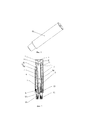
0025 ФИГ. 3 - вид в перспективе, в разобранном состоянии, распыляющего устройства, в соответствии с вариантом осуществления настоящего изобретения.FIG. 3 is an exploded perspective view of a spray device in accordance with an embodiment of the present invention.
0026 ФИГ. 4 - вид в перспективе распыляющего седла, в соответствии с вариантом осуществления настоящего изобретения.FIG. 4 is a perspective view of a spray seat in accordance with an embodiment of the present invention.
0027 ФИГ. 5 - вид в разрезе распыляющего седла, в соответствии с вариантом осуществления настоящего изобретения.FIG. 5 is a cross-sectional view of a spray saddle in accordance with an embodiment of the present invention.
0028 ФИГ. 6 - вид в перспективе соединительного устройства, в соответствии с вариантом осуществления настоящего изобретения.FIG. 0028 6 is a perspective view of a connecting device in accordance with an embodiment of the present invention.
0029 ФИГ. 7 - вид в разрезе соединительного устройства, в соответствии с вариантом осуществления настоящего изобретения.FIG. 0029 7 is a sectional view of a connecting device in accordance with an embodiment of the present invention.
0030 ФИГ. 8 - вид в разрезе распыляющего устройства в полуобработанном состоянии, в соответствии с вариантом осуществления настоящего изобретения.0030 FIG. 8 is a sectional view of a spray device in a semi-finished state, in accordance with an embodiment of the present invention.
0031 ФИГ. 9 - вид в разрезе электронной сигареты, в соответствии с вариантом осуществления настоящего изобретения.FIG. 0031 9 is a cross-sectional view of an electronic cigarette in accordance with an embodiment of the present invention.
0032 ФИГ. 10 - вид в разрезе электронной сигареты, в соответствии с вариантом осуществления настоящего изобретения.FIG. 0032 10 is a sectional view of an electronic cigarette in accordance with an embodiment of the present invention.
ПОДРОБНОЕ ОПИСАНИЕ ИЗОБРЕТЕНИЯDETAILED DESCRIPTION OF THE INVENTION
0033 Необходимо указать, что варианты осуществления и все ограничения элементов во всех вариантах осуществления могут быть скомбинированы при условии отсутствия конфликтов. Настоящее изобретение будет подробно описано со ссылками на следующие комбинированные чертежи и варианты осуществления.0033 It must be pointed out that the embodiments and all the limitations of the elements in all embodiments can be combined provided that there are no conflicts. The present invention will be described in detail with reference to the following combined drawings and embodiments.
0034 Обращаясь к ФИГ. 1-3, распыляющее устройство 10, в соответствии с одним вариантом осуществления настоящего изобретения, включает крышку 1 элемента, посредством которого осуществляется затяжка, наружную втулку 2, аккумулирующий слой для масла 3, тканевый слой 4, трубку из стекловолокна 5, нагревательный узел 6, распыляющее седло 7 и соединительный узел 8. Аккумулирующий слой для масла 3, тканевый слой 4, трубка из стекловолокна 5 и нагревательный узел 6 - все собраны в наружной втулке 2. Распыляющее седло 7 и соединительный узел 8 упруго сжаты относительно друг друга и собраны у одного конца наружной втулки 2 или в наружной втулке 2. Крышка 1 элемента, посредством которого осуществляется затяжка, закрывает другой конец наружной втулки 2. Распыляющее седло 7 представляет собой упругое распыляющее седло, при этом в нем образована щель 73, а в центре сформирован воздушный канал 74. Соединительный узел 8 включает соединительное устройство 81 и дуговой электрод 83. Соединительное устройство 81 и дуговой электрод 83 электроизолированы и собраны вместе. Соединительный узел 8 вставлен в упругое распыляющее седло 7 и упруго взаимодействует с упругим распыляющим седлом 7 при сжатии. Конкретно, соединительное устройство 81 с созданием растягивающего напряжения вставлено в щель 73 упругого распыляющего седла 7, а дуговой электрод 83 с созданием растягивающего напряжения вставлен в воздушный канал 74 распыляющего седла 7. Распыляющее седло обладает большей прочностью после того, как оно вставлено в соединительный узел 8, что также улучшает конструкцию другого элемента. Распыляющее седло 7 может быть лучше уплотнено на одном конце внутренней стенки наружной втулки 2.0034 Referring to FIG. 1-3, a
0035 В этом варианте осуществления, распыляющая втулка 2 выполнена полой, трубчатой формы. Двумя концами наружной втулки 2 являются конец 21 элемента, посредством которого осуществляется затяжка, и соединительный конец 23. Крышка 1 элемента, посредством которого осуществляется затяжка, и соединительный узел 8, соответственно, собраны у конца 21 элемента, посредством которого осуществляется затяжка, и соединительного конца 23. Аккумулирующий слой для масла 3, тканевый слой 4, трубка из стекловолокна 5 и нагревательный узел 6 зафиксированы в наружной втулке 2. Распыляющее седло 7 зафиксировано и уплотнено в соединительном конце 23 наружной втулки 2 относительно крышки 1 элемента, посредством которого осуществляется затяжка, и также взаимодействует с соединительным узлом 8. Конец 21 элемента, посредством которого осуществляется затяжка, наружной втулки 2 образует демпфирующее кольцо 25 на ее внутренней стенке.0035 In this embodiment, the
0036 Крышка 1 элемента, посредством которого осуществляется затяжка, подогнана к наружной втулке 2. Крышка 1 элемента, посредством которого осуществляется затяжка, выполнена в форме кольца, но может иметь иную форму, такую как круглая или коническая. Материал и форма крышки 1 элемента, посредством которого осуществляется затяжка, адаптированы ко рту пользователя, например она сделана из мягкого или древесного материала. В центре крышки 1 элемента, посредством которого осуществляется затяжка, образовано воздушное отверстие 11. В этом варианте осуществления для достижения лучшего уплотнения крышка 1 элемента, посредством которого осуществляется затяжка, снабжена сформированным в ней уплотнительным кольцом 12, которое подогнано к внутреннему диаметру наружной втулки 2. Крышка 1 элемента, посредством которого осуществляется затяжка, и уплотнительное кольцо 12 уплотняют конец 21 элемента, посредством которого осуществляется затяжка, и совместно образуют воздушные отверстия. Центральная часть уплотнительного кольца 12 или крышка 1 элемента, посредством которого осуществляется затяжка, в продольном направлении выступают, образуя опорный участок 13 (13'), который вставлен в трубку из стекловолокна 5, для образования опоры одного конца трубки из стекловолокна 5. В центре уплотнительного кольца 12 образовано воздушное отверстие 15 для сообщения с воздушным отверстием 11 крышки 1 элемента, посредством которого осуществляется затяжка, и трубкой из стекловолокна 5. Кромка уплотнительного кольца 12 упирается в демпфирующее кольцо 25 наружной втулки, при этом поддерживающий участок 23 обращен к демпфирующему кольцу 25 и вставлен в его центральное отверстие.0036 The
0037 Аккумулирующий слой для масла 3 в этом варианте осуществления представляет собой полую трубку, используется для адсорбции или хранения жидкости с запахом табака и расположен в наружной втулке 2. Предпочтительно, аккумулирующий слой для масла 3 выполнен из материала, обладающего функцией адсорбции или хранения, такого как вата или волокнистый материал. Аккумулирующий слой для масла 3 аксиально наложен на внутреннюю стенку наружной втулки 2, при этом два конца аккумулирующего слоя для масла 3, соответственно, упираются в демпфирующее кольцо 25 наружной втулки 2 и распыляющее седло 7.0037 The
0038 В этом варианте осуществления дополнительно описан тканевый слой 4, расположенный между трубкой из стекловолокна 5 и аккумулирующим слоем для масла 3. Тканевый слой 4 может быть выполнен в виде хлопковой ткани, волокнистой ткани, полимерной ткани и так далее. Основная функция тканевого слоя 4 заключается в наложении на трубку из стекловолокна 5 для стабильной сборки трубки из стекловолокна 5 нагревательного узла 6, распыляющего узла 7 и соединительного узла 8 вместе, чтобы обеспечить стабильное подключение и надежное уплотнение электрической цепи. Кроме того, функция тканевого слоя 4 заключается в обеспечении подведения жидкости с запахом табака к нагревательному узлу 6 от аккумулирующего слоя для масла 3, чтобы не допустить утечки жидкости с запахом табака по промежутку между наружной втулкой 2 и соединительным устройством 81.0038 In this embodiment, a
0039 Трубка из стекловолокна 5 представляет собой полую трубку, зафиксированную в тканевом слое 4. Соответствующим образом, аккумулирующий слой для масла 3 и тканевый слой 4 размещены на наружной поверхности трубки из стекловолокна 5 с образованием трубки. В стенке трубки из стекловолокна 5 выполнено сборочное отверстие 53, для сборки нагревательного узла 6. Трубка из стекловолокна 5 продольно и аксиально поддерживается в аккумулирующем слое для масла 3 и тканевом слое 4. Один конец трубки из стекловолокна 5 защелкнут между демпферным кольцом 25 наружной втулки 2 и опорным участком 13 уплотнительного кольца 12, для фиксации уплотнительного кольца 12 или крышки 1 элемента, посредством которого осуществляется затяжка, и трубки из стекловолокна 5. Другой конец трубки из стекловолокна 5 защелкнут в распыляющем седле 7. Предпочтительно, на внутренней стенке сборочного отверстия 53 образована пара поддерживающих серег 54, которые целесообразно использовать для опоры нагревательного узла 6. Далее, для упрочнения трубки из стекловолокна 5 аккумулирующего слоя для масла 3 и тканевого слоя 4, трубка из стекловолокна 5 спроектирована как двухслойная трубка, содержащая трубку 51 внутреннего слоя и трубку 52 наружного слоя. Трубка наружного слоя 52 дополнительно, с обеспечением плотного контакта, собрана на нагревательном узле 6 трубки 51 внутреннего слоя. Следует иметь в виду, что трубка из стекловолокна 5 может быть и однослойной трубкой.0039 A
0040 Нагревательный узел 6 включает нагревательный провод 60 и электронные провода 61, 63 (соответственно, отрицательный или положительный электроды), отходящие от двух концов нагревательного провода 60. Нагревательный провод 60 может быть обмотан или свернут или иметь другую структуру, чтобы контактировать с аккумулирующим слоем для масла 3 и тканевым слоем 4, используемыми для нагрева и испарения жидкости с запахом табака. В этом варианте осуществления нагревательный провод 60 обмотан до получения формы спирали, в виде которой он вставлен в проводящую жидкость ленту или проводящий жидкость штырь 65, для фиксации нагревательного провода 60 в трубке из стекловолокна 5. Два конца проводящей жидкость ленты (штыря) 65 радиально проходят через сборочное отверстие 53 трубки из стекловолокна 5 и упираются в аккумулирующий слой для масла 3 так, чтобы адсорбировать жидкость с запахом табака, испаряемую нагревательным проводом 60.0040 The
0041 Обращаясь также к ФИГ. 4 и 5, упругое распыляющее седло 7 представляет собой силиконовое распыляющее седло и включает основной корпус 70 и выступающий участок 72. Основной корпус 70 выполнен, в основном, колоннообразной формы. Выступающий участок 72 - колоннообразный и аксиально проходит на предварительно определенное расстояние от центра основного корпуса 70. После сборки выступающий участок 72 плотно вставлен в один конец трубки из стекловолокна 5 в противоположном конце от крышки 1 элемента, посредством которого осуществляется затяжка. Выступающий участок 72 и основной корпус 70 вместе образуют центральный воздушный канал 74, который сообщается с внешней средой и трубкой из стекловолокна 5, тем самым сообщается с воздушным отверстием 11 крышки 1 элемента, посредством которого осуществляется затяжка, и воздушным отверстием 15 уплотнительного кольца 12 и, наконец, сообщается с внешней средой, образуя воздушный канал. Основной корпус 70 образует кольцевой фланец 71 на своей наружной кромке. Наружный диаметр кольцевого фланца 71 подогнан под внутренний диаметр наружной втулки 2 и плотно защелкивается на внутренней стенке соединительного конца 23 наружной втулки 2. Кольцевой фланец 71 и наружная стенка основного корпуса 70 вместе ограничивают щель 73, которая является кольцевой щелью. Основной корпус 70 образует пару отверстий для линий 75, 77. Одно отверстие для линии 77 сообщается с центральным воздушным каналом 74. Предпочтительно, каждое отверстие для линии 75, 77 расположено так, чтобы иметь разный внутренний диаметр, и, соответственно, выполнено с узкими горлышками 750, 770, используемыми для электронных проводов 61, 63, проходящих через них и зажатых узкими горлышками 750, 770. В этом варианте осуществления основной корпус 70 имеет чашеобразную форму, а кольцевой фланец 71 - такой же, в отношении кромки чаши. Очевидно, что основной корпус 70 может быть выполнен и другой формы.0041 Referring also to FIG. 4 and 5, the
0042 Как представлено на ФИГ. 6 и 7, соединительное устройство 81 представляет собой твердый проводящий элемент, предпочтительно металлический элемент. Дуговой электрод 83 вставлен в соединительное устройство 81, при этом изолирующее кольцо 85 вставлено между дуговым электродом 83 и соединительным устройством 81 для обеспечения изоляции. Соединительное устройство 81, по существу, является полой колонкой и образует ступенчатое отверстие 810. Внутренняя стенка ступенчатого отверстия 810 образует первый внутренний заплечик 812 и второй внутренний заплечик 814. Один конец соединительного устройства 81, будучи вставленным в щель 73 распыляющего седла 7, является вставным концом 811. Соответствуя глубине щели 73 распыляющего седла 7 и кольцевого фланца 71, наружная стенка соединительного устройства 81, отнесенная от вставляющего конца 811 на предварительно определенное расстояние, образует наружный кольцевой фланец 813. Вставной конец 811 вставлен в щель 73 распыляющего седла 7, чтобы обеспечить опору для упругого распыляющего седла 7, так чтобы сделать упругое распыляющее седло 7 более прочным. В одном варианте осуществления наружный кольцевой фланец 813 может быть выполнен ступенчатой формы и включает первую ступень 8130 и вторую ступень 8132. Наружный диаметр первой ступени 8130 подогнан к внутреннему диаметру наружной втулки 2 и плотно защелкнут в соединительном конце 23 наружной втулки 2 и также в продольном направлении упирается в удаленный конец кольцевого фланца 71 распыляющего седла 7. Основной корпус 70 распыляющего седла 7 с созданием растягивающего напряжения вставлен в ступенчатое отверстие 810 и упирается в первый внутренний заплечик 812 так, чтобы дополнительно уплотнить и зафиксировать наружную втулку 2 и распыляющее седло 7. Кромка соединительного конца 23 наружной втулки 2 упирается во вторую ступень 8132. Второй внутренний заплечик 814 в действительности представляет собой выступающее кольцо, образованное на внутренней стенке соединительного устройства 81. Изолирующее кольцо 85 вставлено в ступенчатое отверстие 810 через другой конец, противоположный вставляющему концу 811, и защелкнуто со вторым внутренним заплечиком 814. Дуговой электрод 83 вставлен в изолирующее кольцо 85 и защелкнут в нем. Дуговой электрод 83 выполнен длинным и колоннообразным и образует фланец на своем удаленном конце для защелкивания в изолирующем кольце 85. Колоннообразный участок дугового электрода 83 вставлен и, с созданием растягивающего напряжения, зафиксирован в центральном воздушном канале 74 распыляющего седла 7 через соединительное устройство 81 для дополнительной опоры и упругого сжатия силиконового распыляющего седла 7. Боковая стенка дугового электрода 83 и соединительное устройство 81, соответственно, образуют воздушное отверстие (не обозначено), которое сообщается с воздушным каналом, совместно образованным соединительным узлом 8, распыляющим седлом 7, трубкой из стекловолокна 5, уплотнительным кольцом 12 и крышкой 1 элемента, посредством которого осуществляется затяжка, таким образом, что наружный воздух втягивается внутрь и выбрасывается наружу с дымом, создаваемым распыляющим устройством 10.0042 As presented in FIG. 6 and 7, the connecting
0043 На ФИГ. 8 представлено изделие в полуобработанном состоянии, нагревательный провод 60 зафиксирован в трубке из стекловолокна 5, а электронные провода 61, 63 пропущены через сборочное отверстие 50 и выходят вдоль наружной стенки трубки из стекловолокна 5. Два конца проводящей жидкость ленты (стойки) 65 пропущены через сборочное отверстие 50. В то же время электронные провода 61, 63, соответственно, пропущены через отверстия для линий 75, 77 силиконового распыляющего седла 7. Электронный провод 63 пропущен через отверстие для линии 77 и изогнут к внутренней стенке центрального воздушного канала 74 распыляющего седла 7. Электронная линия 61 пропущена через отверстие для линии 75, а затем изогнута в щель 73 от кромки основного корпуса 70. Вставной конец 811 соединительного устройства 81 вставлен в щель 73 силиконового распыляющего седла 7 и плотно защелкивает электронные провода 61. Дуговой электрод 83 вставлен в центральный воздушный канал 74 распыляющего седла 7 и плотно защелкивает электронную линию 63. Участок дугового электрода 83 в форме колонны сжимает силиконовое распыляющее седло 7 из центрального воздушного отверстия 74 распыляющего седла 7. Таким образом, электронные провода 63 зажаты между внутренней стенкой распыляющего седла 7 и наружной стенкой дугового электрода 83 и, таким образом, электрически подсоединены к дуговому электроду 83. Когда вставной конец 811 металлического соединительного устройства 81 вставлен в щель 73 распыляющего седла 7, вставной конец 811 сжимает кольцевой фланец 71 и основной корпус 70 распыляющего седла 7 так, что электронный провод 63 плотно защелкивается в щели 73 распыляющего седла 7 и, таким образом, стабильно электрически подсоединен к металлическому соединительному устройству 81. После того как металлическое соединительное устройство 81 и дуговой электрод 83 вставлены в распыляющее седло 7, силиконовое распыляющее седло 7 упруго прижато внутрь для дополнительного защелкивания электронных проводов 61, 63, пропущенных через отверстия для линий 75, 77, особенно их защелкивания в тонких шейках 750, 770. Таким образом, электронные провода 61, 63 нельзя вытянуть. Одновременно кольцевой фланец 71 силиконового распыляющего седла 7 выдавлен наружу и расширяется так, чтобы обеспечить равномерное защелкивание на внутренней стенке наружной втулки 2, тем самым достигается лучший эффект уплотнения. К тому же, после того, как соединительное устройство 81 и дуговой электрод 83 вставлены в силиконовое распыляющее седло 7, повышается общая жесткость и прочность распыляющего устройства. Таким образом, становится удобным держать соединительное устройство 81, чтобы наложить тканевый слой 4 и аккумулирующий слой для масла 3 на трубку из стекловолокна 5. Аккумулирующий слой для масла 3 по настоящему варианту осуществления выполнен из упаковочной ваты. Сборка является удобной. После накладки тканевого слоя 4 и аккумулирующего слоя для масла 3 на трубку из стекловолокна 5 на трубку 5 устанавливают наружную втулку. Затем конец элемента 21, посредством которого осуществляется затяжка, вставляют в уплотнительное кольцо 12 и крышку 1 элемента, посредством которого осуществляется затяжка. Таким образом, распыляющее устройство 10 полностью собрано. Благодаря упругому взаимодействию между металлическим соединительным устройством 81, дуговым электродом 83 и силиконовым распыляющим седлом 7 электронные провода 61, 63 распыляющего устройства 10, в соответствии с настоящим изобретением, плотно запрессованы и стабильно электрически подключены к металлическому соединительному устройству 81 и дуговому электроду 83, при этом нет необходимости в какой-либо сварке, снижаются затраты, и исключена возможность образования каких-либо вредных веществ. Кроме того, силиконовое распыляющее седло 7 вставлено во втулку в соединительном узле 8 и запрессовано для расширения в наружном направлении, чтобы обеспечить герметизацию распыляющего седла 7 в наружной втулке 2, не деформируется и не скользит.0043 In FIG. 8 shows the product in a semi-finished state, the
0044 На Фиг. 9 электронная сигарета, в соответствии с настоящим изобретением, включает распыляющее устройство 10 и полюс 100 источника питания. Распыляющее устройство 10 и полюс источника питания 100 соединены друг с другом с образованием разъемного или неразъемного соединения. Полюс источника питания 100 включает расположенную в нем аккумуляторную батарею 101. Один конец полюса источника питания 100 приспособлен для соединительного конца распыляющего устройства 10 и может быть подсоединен к соединительному концу распыляющего устройства 10 резьбовым соединением, защелкивающимся соединением, соединением с созданием растягивающего напряжения, клеевым соединением или формованием в виде единого целого. При эксплуатации полюс источника питания 100 соединяется с распыляющим устройством 10, при этом дуговой электрод 83 и металлическое соединительное устройство 81, соответственно, соединены с положительным и отрицательным электродами полюса источника питания 100, чтобы подводить питание к нагревательному проводу.0044 In FIG. 9, an electronic cigarette according to the present invention includes a
0045 На Фиг. 10 изображена одноразовая электронная сигарета 100. Наружная втулка 2 содержит сплошную наружную втулку 2' электронной сигареты 100. Одноразовая электронная сигарета 100 разделена на две части. Одна часть соответствует распыляющему устройству 10, а другая часть соответствует полюсу источника питания 100. Сборка каждой части выполняется так же, как описано выше. Отличие состоит в том, что распыляющее седло 7 и соединительный узел 8 собраны в наружной втулке 2', вместо сборки их в удаленном конце. Аккумуляторная батарея 101 находится в наружной втулке 2' и взаимодействует с соединительным узлом 8. Положительный и отрицательный электроды источника питания, соответственно, электрически подключены к соединительному устройству и электронным проводам 63 нагревательного узла 6, для достижения, таким образом, электрической связи с электронными проводами 61, 63 нагревательного узла 6. Наружная втулка 2' снабжена крышкой 103 аккумуляторной батареи, расположенной на другом ее конце, противоположном крышке 1 элемента, посредством которого осуществляется затяжка. В одноразовой электронной сигарете 100 положительный и отрицательный электроды аккумуляторной батареи, соответственно, электрически подсоединены к электронным линиям 61, 63 нагревательного узла 6, таким образом, можно обойтись без дугового электрода 83.0045 In FIG. 10 shows a disposable
0046 На ФИГ. 10 крышка 1 элемента, посредством которого осуществляется затяжка, и уплотнительное кольцо 12 защелкнуты друг с другом, при этом выступающий участок 13', вставляемый в трубку из стекловолокна 5, может быть сконструирован так, чтобы аксиально выступать из крышки 1 элемента, посредством которого осуществляется затяжка. Силиконовое распыляющее седло 7 может иметь поперечное сечение Н-образной формы, с образованием, таким образом, щелей 73, 79 на двух его концах. Щель 79 используется для защелкивания одного вставляемого конца трубки из стекловолокна 5, чтобы затем зафиксировать ее и обеспечить соответствующее положение.0046 In FIG. 10, the
0047 Надо иметь в виду, что электронная сигарета может быть электронной сигаретой многократного применения. Распыляющее устройство 10 и полюс источника питания 100 могут быть соединены друг с другом неразъемным соединением. Распыляющее устройство 10 может быть оснащено чашей для жидкости, для аккумулирования в ней жидкости с запахом табака или другого жидкого компонента. В другом варианте осуществления жидкость с запахом табака можно неоднократно добавлять. Например, крышка 1 элемента, посредством которого осуществляется затяжка, и уплотнительное кольцо 12 скомпонованы таким образом, чтобы образовать съемную структуру, для неоднократного залива внутрь жидкости с запахом табака.0047 It must be borne in mind that an electronic cigarette may be a multiple-use electronic cigarette. The
0048 Тканевый слой 4 данного варианта осуществления, в соответствии с настоящим изобретением, можно не использовать, согласно конкретным требованиям, или его можно заменить другим материалом. Кроме того, нагревательный провод 6 нагревательного узла 6 может быть и другим нагревательным элементом, таким как нагревательный блок, нагревательный стержень или другими элементами, с помощью которых может быть осуществлен нагрев. Электронные провода 61, 63, подсоединенные к двум концам нагревательного элемента, проходят через упругое распыляющее седло 7 и зафиксированы в нем, с созданием растягивающего напряжения, а затем - электрически подключены к соединительному узлу 8.0048 The
0049 Все вышеупомянутое представляет варианты осуществления настоящего изобретения. Следует отметить, что возможны разнообразные усовершенствования и модификации данных вариантов осуществления специалистами в данной области техники, не выходя за рамки истинной сущности и объема данного изобретения, которые определены приложенной формулой изобретения.0049 All of the above represent embodiments of the present invention. It should be noted that various improvements and modifications to these embodiments are possible by those skilled in the art, without going beyond the true nature and scope of the invention, which are defined by the appended claims.
Claims (15)
Applications Claiming Priority (7)
| Application Number | Priority Date | Filing Date | Title |
|---|---|---|---|
| CN201220141170.8 | 2012-04-01 | ||
| CN2012201411708U CN202618275U (en) | 2012-04-01 | 2012-04-01 | Electronic cigarette and suction nozzle thereof |
| CNPCT/CN2012/076493 | 2012-06-05 | ||
| PCT/CN2012/076493 WO2013181797A1 (en) | 2012-06-05 | 2012-06-05 | Electronic cigarette and suction rod thereof |
| CNPCT/CN2012/076492 | 2012-06-05 | ||
| PCT/CN2012/076492 WO2013181796A1 (en) | 2012-06-05 | 2012-06-05 | Electronic cigarette and suction rod thereof |
| PCT/CN2012/086685 WO2013149484A1 (en) | 2012-04-01 | 2012-12-14 | Atomization device and electronic cigarette thereof |
Publications (2)
| Publication Number | Publication Date |
|---|---|
| RU2014136936A RU2014136936A (en) | 2016-05-27 |
| RU2603739C2 true RU2603739C2 (en) | 2016-11-27 |
Family
ID=49299961
Family Applications (1)
| Application Number | Title | Priority Date | Filing Date |
|---|---|---|---|
| RU2014136936/12A RU2603739C2 (en) | 2012-04-01 | 2012-12-14 | Atomising device and electronic cigarette using same |
Country Status (7)
| Country | Link |
|---|---|
| EP (1) | EP2835062B1 (en) |
| JP (1) | JP5978453B2 (en) |
| KR (1) | KR101684756B1 (en) |
| AU (1) | AU2012376065A1 (en) |
| CA (1) | CA2868914C (en) |
| RU (1) | RU2603739C2 (en) |
| WO (1) | WO2013149484A1 (en) |
Cited By (4)
| Publication number | Priority date | Publication date | Assignee | Title |
|---|---|---|---|---|
| RU2711315C1 (en) * | 2016-11-29 | 2020-01-16 | Филип Моррис Продактс С.А. | Aerosol-generating system and a method for supplying a liquid aerosol-forming substrate by means of injected air |
| US10653185B2 (en) | 2016-11-29 | 2020-05-19 | Altria Client Services Llc | Aerosol-generating system and method of dispensing liquid aerosol-forming substrate with pumped air |
| US11452826B2 (en) | 2016-03-24 | 2022-09-27 | Nicoventures Trading Limited | Mechanical connector for electronic vapor provision system |
| RU2816172C1 (en) * | 2021-12-23 | 2024-03-26 | Шэньчжэнь Хуачэнда Пресижен Индастри Ко. Лтд. | Spraying device with good spraying effect |
Families Citing this family (42)
| Publication number | Priority date | Publication date | Assignee | Title |
|---|---|---|---|---|
| AT507187B1 (en) | 2008-10-23 | 2010-03-15 | Helmut Dr Buchberger | INHALER |
| AT510837B1 (en) | 2011-07-27 | 2012-07-15 | Helmut Dr Buchberger | INHALATORKOMPONENTE |
| ES2543312T3 (en) | 2011-02-11 | 2015-08-18 | Batmark Limited | Component for inhaler |
| KR102353233B1 (en) | 2011-09-06 | 2022-01-18 | 니코벤처스 트레이딩 리미티드 | Heating smokable material |
| JP5808490B2 (en) | 2011-09-06 | 2015-11-10 | ブリティッシュ アメリカン タバコ (インヴェストメンツ) リミテッドBritish Americantobacco (Investments) Limited | Smoking material heating |
| AT511344B1 (en) | 2011-10-21 | 2012-11-15 | Helmut Dr Buchberger | INHALATORKOMPONENTE |
| GB201207039D0 (en) | 2012-04-23 | 2012-06-06 | British American Tobacco Co | Heating smokeable material |
| GB2504076A (en) | 2012-07-16 | 2014-01-22 | Nicoventures Holdings Ltd | Electronic smoking device |
| US10034988B2 (en) | 2012-11-28 | 2018-07-31 | Fontem Holdings I B.V. | Methods and devices for compound delivery |
| EP2941969A4 (en) * | 2013-01-05 | 2016-07-20 | Huizhou Kimree Technology Co Ltd Shenzhen Branch | Electronic cigarette device, electronic cigarette and atomization device thereof |
| CN105142441B (en) * | 2013-04-11 | 2019-06-28 | 吉瑞高新科技股份有限公司 | Electronic cigarette |
| GB2513638A (en) | 2013-05-02 | 2014-11-05 | Nicoventures Holdings Ltd | Electronic cigarette |
| GB2513637A (en) | 2013-05-02 | 2014-11-05 | Nicoventures Holdings Ltd | Electronic cigarette |
| GB2513639A (en) | 2013-05-02 | 2014-11-05 | Nicoventures Holdings Ltd | Electronic cigarette |
| WO2015042412A1 (en) | 2013-09-20 | 2015-03-26 | E-Nicotine Technology. Inc. | Devices and methods for modifying delivery devices |
| CN203575655U (en) * | 2013-11-12 | 2014-05-07 | 深圳市合元科技有限公司 | Oil plug for electronic cigarette and electronic cigarette |
| CN103584286A (en) * | 2013-11-12 | 2014-02-19 | 深圳市合元科技有限公司 | Atomizer, electronic cigarette and atomization head for electronic cigarette |
| WO2015078147A1 (en) * | 2013-11-28 | 2015-06-04 | Hk Triangle Co., Limited | Electronic cigarette atomizer |
| CN203646506U (en) | 2013-12-09 | 2014-06-18 | 刘秋明 | Soft atomizer connector fixing structure and electronic cigarette |
| WO2015096107A1 (en) * | 2013-12-26 | 2015-07-02 | 吉瑞高新科技股份有限公司 | Atomization apparatus, electronic cigarette, and assembly method therefor |
| US9974334B2 (en) * | 2014-01-17 | 2018-05-22 | Rai Strategic Holdings, Inc. | Electronic smoking article with improved storage of aerosol precursor compositions |
| EP2907398A1 (en) * | 2014-01-27 | 2015-08-19 | Shenzhen Smaco Technology Limited | Disposable electronic cigarette |
| WO2015149281A1 (en) * | 2014-04-01 | 2015-10-08 | 吉瑞高新科技股份有限公司 | Electronic cigarette, battery pole and atomizer |
| GB201407426D0 (en) | 2014-04-28 | 2014-06-11 | Batmark Ltd | Aerosol forming component |
| CN203952447U (en) * | 2014-06-25 | 2014-11-26 | 林光榕 | Electronic cigarette |
| GB2528673B (en) | 2014-07-25 | 2020-07-01 | Nicoventures Holdings Ltd | Aerosol provision system |
| GB2533135B (en) | 2014-12-11 | 2020-11-11 | Nicoventures Holdings Ltd | Aerosol provision systems |
| CN204444245U (en) * | 2015-01-05 | 2015-07-08 | 深圳市合元科技有限公司 | Removable atomization unit and the atomizer and the electronic cigarette that comprise this atomization unit |
| CN105266205B (en) * | 2015-04-13 | 2018-01-09 | 深圳瀚星翔科技有限公司 | Electronic cigarette and atomizer and oiling bottle |
| GB201511349D0 (en) | 2015-06-29 | 2015-08-12 | Nicoventures Holdings Ltd | Electronic aerosol provision systems |
| US11924930B2 (en) | 2015-08-31 | 2024-03-05 | Nicoventures Trading Limited | Article for use with apparatus for heating smokable material |
| US20170055584A1 (en) | 2015-08-31 | 2017-03-02 | British American Tobacco (Investments) Limited | Article for use with apparatus for heating smokable material |
| US20180310623A1 (en) * | 2015-10-22 | 2018-11-01 | Philip Morris Products S.A. | Aerosol generating article, aerosol-generating system and method for manufacturing an aerosol-generating article |
| BR112018071824B1 (en) | 2016-04-27 | 2023-01-10 | Nicoventures Trading Limited | SUB-ASSEMBLY, SYSTEM, METHOD FOR MANUFACTURING A VAPORIZER AND ELECTRONIC STEAM DELIVERY DEVICE |
| WO2018069995A1 (en) | 2016-10-12 | 2018-04-19 | 日本たばこ産業株式会社 | Flavor inhaler |
| US10314340B2 (en) * | 2017-04-21 | 2019-06-11 | Rai Strategic Holdings, Inc. | Refillable aerosol delivery device and related method |
| CN109717510A (en) * | 2017-10-30 | 2019-05-07 | 日本烟草产业株式会社 | Atomization unit and fragrance extractor |
| GB201903302D0 (en) * | 2019-03-11 | 2019-04-24 | Nicoventures Trading Ltd | Aerosol-generating device |
| US11882876B2 (en) | 2019-07-23 | 2024-01-30 | Kt&G Corporation | Cartridge and aerosol generating device including the same |
| KR102328200B1 (en) * | 2019-07-23 | 2021-11-17 | 주식회사 케이티앤지 | A cartridge and an aerosol generating apparatus comprising thereof |
| CN112390625B (en) * | 2019-08-12 | 2021-12-28 | 深圳麦克韦尔科技有限公司 | Composite ceramic part, preparation method thereof, atomization assembly and electronic cigarette |
| CN215531606U (en) * | 2021-06-28 | 2022-01-18 | 深圳市华诚达精密工业有限公司 | Atomizer |
Citations (2)
| Publication number | Priority date | Publication date | Assignee | Title |
|---|---|---|---|---|
| CN201072979Y (en) * | 2007-07-20 | 2008-06-18 | 李永海 | Atomizer used for electronic cigarette |
| CN102326869A (en) * | 2011-05-12 | 2012-01-25 | 陈志平 | Atomization nozzle of electronic atomization inhaler |
Family Cites Families (15)
| Publication number | Priority date | Publication date | Assignee | Title |
|---|---|---|---|---|
| US4819665A (en) * | 1987-01-23 | 1989-04-11 | R. J. Reynolds Tobacco Company | Aerosol delivery article |
| US6558180B2 (en) * | 2001-05-18 | 2003-05-06 | Shimano Inc. | Waterproof electrical connector |
| EP1609376A1 (en) * | 2003-04-01 | 2005-12-28 | Shusei Takano | Nicotine suction pipe and nicotine holder |
| JP2010104310A (en) * | 2008-10-31 | 2010-05-13 | Samuraing Co Ltd | Pseudo-smoking supplies |
| CN201379072Y (en) * | 2009-02-11 | 2010-01-13 | 韩力 | Improved atomizing electronic cigarette |
| CN101606758B (en) * | 2009-07-14 | 2011-04-13 | 方晓林 | Electronic cigarette |
| CN201467998U (en) * | 2009-07-14 | 2010-05-19 | 方晓林 | Electronic cigarette |
| KR101133052B1 (en) * | 2009-07-15 | 2012-04-04 | 주식회사 진성엘엔엘 | Fixing apparatus of green street tree |
| CN101843368A (en) * | 2010-04-02 | 2010-09-29 | 陈志平 | Suction nozzle of electronic atomizer |
| CN201830900U (en) * | 2010-06-09 | 2011-05-18 | 李永海 | Tobacco juice atomization device for electronic cigarette |
| CN102160906B (en) * | 2010-11-01 | 2012-08-08 | 常州市富艾发进出口有限公司 | Oral-suction type portable atomizer |
| CN201860753U (en) * | 2010-12-09 | 2011-06-15 | 深圳市施美乐科技有限公司 | Disposable atomizing device of electronic cigarette |
| KR101081481B1 (en) * | 2011-06-13 | 2011-11-08 | 김형윤 | Cartridge having pulverizer for electronic cigarette |
| KR101184758B1 (en) * | 2012-01-13 | 2012-09-19 | 이영인 | Cartridge of electric cigarette for preventing leakage |
| US9282772B2 (en) * | 2012-01-31 | 2016-03-15 | Altria Client Services Llc | Electronic vaping device |
-
2012
- 2012-12-14 WO PCT/CN2012/086685 patent/WO2013149484A1/en active Application Filing
- 2012-12-14 EP EP12873614.7A patent/EP2835062B1/en not_active Not-in-force
- 2012-12-14 AU AU2012376065A patent/AU2012376065A1/en not_active Abandoned
- 2012-12-14 KR KR1020147026506A patent/KR101684756B1/en active IP Right Grant
- 2012-12-14 CA CA2868914A patent/CA2868914C/en not_active Expired - Fee Related
- 2012-12-14 RU RU2014136936/12A patent/RU2603739C2/en not_active IP Right Cessation
- 2012-12-14 JP JP2015502062A patent/JP5978453B2/en not_active Expired - Fee Related
Patent Citations (2)
| Publication number | Priority date | Publication date | Assignee | Title |
|---|---|---|---|---|
| CN201072979Y (en) * | 2007-07-20 | 2008-06-18 | 李永海 | Atomizer used for electronic cigarette |
| CN102326869A (en) * | 2011-05-12 | 2012-01-25 | 陈志平 | Atomization nozzle of electronic atomization inhaler |
Cited By (5)
| Publication number | Priority date | Publication date | Assignee | Title |
|---|---|---|---|---|
| US11452826B2 (en) | 2016-03-24 | 2022-09-27 | Nicoventures Trading Limited | Mechanical connector for electronic vapor provision system |
| RU2711315C1 (en) * | 2016-11-29 | 2020-01-16 | Филип Моррис Продактс С.А. | Aerosol-generating system and a method for supplying a liquid aerosol-forming substrate by means of injected air |
| US10653185B2 (en) | 2016-11-29 | 2020-05-19 | Altria Client Services Llc | Aerosol-generating system and method of dispensing liquid aerosol-forming substrate with pumped air |
| US10980287B2 (en) | 2016-11-29 | 2021-04-20 | Altria Client Services Llc | Aerosol-generating system and method of dispensing liquid aerosol-forming substrate with pumped air |
| RU2816172C1 (en) * | 2021-12-23 | 2024-03-26 | Шэньчжэнь Хуачэнда Пресижен Индастри Ко. Лтд. | Spraying device with good spraying effect |
Also Published As
| Publication number | Publication date |
|---|---|
| AU2012376065A1 (en) | 2014-10-02 |
| KR101684756B1 (en) | 2016-12-08 |
| EP2835062A4 (en) | 2015-11-04 |
| RU2014136936A (en) | 2016-05-27 |
| CA2868914C (en) | 2017-01-03 |
| EP2835062A1 (en) | 2015-02-11 |
| WO2013149484A1 (en) | 2013-10-10 |
| KR20140128449A (en) | 2014-11-05 |
| CA2868914A1 (en) | 2013-10-10 |
| JP2015511495A (en) | 2015-04-20 |
| EP2835062B1 (en) | 2018-09-05 |
| JP5978453B2 (en) | 2016-08-24 |
Similar Documents
| Publication | Publication Date | Title |
|---|---|---|
| RU2603739C2 (en) | Atomising device and electronic cigarette using same | |
| US9456633B2 (en) | Atomizing device and electronic cigarette using the same | |
| RU2602964C2 (en) | Suction rod for electronic cigarette and electronic cigarette using said rod | |
| CN107205485B (en) | Atomization component and electronic cigarette | |
| EP3398462B1 (en) | Atomizer and electronic cigarette having same | |
| US9497994B2 (en) | Electronic cigarette device, electronic cigarette, and atomizing device used in the same | |
| US9603387B2 (en) | Electronic cigarette and its soft sucking rod | |
| CN104023571B (en) | Electronic Cigarette And Suction Rod Thereof | |
| CN203168030U (en) | Atomization device and electronic cigarette thereof | |
| US9723872B2 (en) | Electronic cigarette and soft power source stem thereof | |
| US10306930B2 (en) | Heating device, and atomizing head, atomizer and electronic cigarette having the same | |
| US20140109921A1 (en) | Electronic cigarette | |
| US20140332022A1 (en) | Atomizing device and electronic cigarette having same | |
| WO2016119167A1 (en) | Atomization assembly and electronic cigarette | |
| US20150196055A1 (en) | Electronic cigarette | |
| EP3127437A1 (en) | Electronic cigarette | |
| US20140246031A1 (en) | Electronic Cigarette and Soft Enclosure Holding Device Thereof | |
| CN107404944A (en) | A kind of atomizing component and electronic cigarette | |
| CN206659108U (en) | Atomizer and electrical smoking device easy to assemble | |
| CN109393569A (en) | Atomising device and electronic cigarette | |
| KR20130003944U (en) | An atomizer for electronic cigarette | |
| CN211298444U (en) | Disposable cigarette cartridge | |
| CN104023573B (en) | Atomising device and electronic cigarette thereof |
Legal Events
| Date | Code | Title | Description |
|---|---|---|---|
| MM4A | The patent is invalid due to non-payment of fees |
Effective date: 20181215 |