RU2596201C2 - Method and device for protection of located in fairing from bending shaft in case - Google Patents
Method and device for protection of located in fairing from bending shaft in case Download PDFInfo
- Publication number
- RU2596201C2 RU2596201C2 RU2014111339/11A RU2014111339A RU2596201C2 RU 2596201 C2 RU2596201 C2 RU 2596201C2 RU 2014111339/11 A RU2014111339/11 A RU 2014111339/11A RU 2014111339 A RU2014111339 A RU 2014111339A RU 2596201 C2 RU2596201 C2 RU 2596201C2
- Authority
- RU
- Russia
- Prior art keywords
- rotor
- stator
- ring
- elements
- windings
- Prior art date
Links
Images
Classifications
-
- H—ELECTRICITY
- H02—GENERATION; CONVERSION OR DISTRIBUTION OF ELECTRIC POWER
- H02K—DYNAMO-ELECTRIC MACHINES
- H02K7/00—Arrangements for handling mechanical energy structurally associated with dynamo-electric machines, e.g. structural association with mechanical driving motors or auxiliary dynamo-electric machines
- H02K7/08—Structural association with bearings
- H02K7/083—Structural association with bearings radially supporting the rotary shaft at both ends of the rotor
-
- B—PERFORMING OPERATIONS; TRANSPORTING
- B23—MACHINE TOOLS; METAL-WORKING NOT OTHERWISE PROVIDED FOR
- B23P—METAL-WORKING NOT OTHERWISE PROVIDED FOR; COMBINED OPERATIONS; UNIVERSAL MACHINE TOOLS
- B23P15/00—Making specific metal objects by operations not covered by a single other subclass or a group in this subclass
- B23P15/003—Making specific metal objects by operations not covered by a single other subclass or a group in this subclass bearings
-
- B—PERFORMING OPERATIONS; TRANSPORTING
- B63—SHIPS OR OTHER WATERBORNE VESSELS; RELATED EQUIPMENT
- B63H—MARINE PROPULSION OR STEERING
- B63H23/00—Transmitting power from propulsion power plant to propulsive elements
- B63H23/32—Other parts
- B63H23/321—Bearings or seals specially adapted for propeller shafts
-
- F—MECHANICAL ENGINEERING; LIGHTING; HEATING; WEAPONS; BLASTING
- F16—ENGINEERING ELEMENTS AND UNITS; GENERAL MEASURES FOR PRODUCING AND MAINTAINING EFFECTIVE FUNCTIONING OF MACHINES OR INSTALLATIONS; THERMAL INSULATION IN GENERAL
- F16C—SHAFTS; FLEXIBLE SHAFTS; ELEMENTS OR CRANKSHAFT MECHANISMS; ROTARY BODIES OTHER THAN GEARING ELEMENTS; BEARINGS
- F16C17/00—Sliding-contact bearings for exclusively rotary movement
- F16C17/12—Sliding-contact bearings for exclusively rotary movement characterised by features not related to the direction of the load
- F16C17/14—Sliding-contact bearings for exclusively rotary movement characterised by features not related to the direction of the load specially adapted for operating in water
-
- F—MECHANICAL ENGINEERING; LIGHTING; HEATING; WEAPONS; BLASTING
- F16—ENGINEERING ELEMENTS AND UNITS; GENERAL MEASURES FOR PRODUCING AND MAINTAINING EFFECTIVE FUNCTIONING OF MACHINES OR INSTALLATIONS; THERMAL INSULATION IN GENERAL
- F16C—SHAFTS; FLEXIBLE SHAFTS; ELEMENTS OR CRANKSHAFT MECHANISMS; ROTARY BODIES OTHER THAN GEARING ELEMENTS; BEARINGS
- F16C17/00—Sliding-contact bearings for exclusively rotary movement
- F16C17/12—Sliding-contact bearings for exclusively rotary movement characterised by features not related to the direction of the load
- F16C17/20—Sliding-contact bearings for exclusively rotary movement characterised by features not related to the direction of the load with emergency supports or bearings
-
- F—MECHANICAL ENGINEERING; LIGHTING; HEATING; WEAPONS; BLASTING
- F16—ENGINEERING ELEMENTS AND UNITS; GENERAL MEASURES FOR PRODUCING AND MAINTAINING EFFECTIVE FUNCTIONING OF MACHINES OR INSTALLATIONS; THERMAL INSULATION IN GENERAL
- F16C—SHAFTS; FLEXIBLE SHAFTS; ELEMENTS OR CRANKSHAFT MECHANISMS; ROTARY BODIES OTHER THAN GEARING ELEMENTS; BEARINGS
- F16C32/00—Bearings not otherwise provided for
- F16C32/06—Bearings not otherwise provided for with moving member supported by a fluid cushion formed, at least to a large extent, otherwise than by movement of the shaft, e.g. hydrostatic air-cushion bearings
- F16C32/0603—Bearings not otherwise provided for with moving member supported by a fluid cushion formed, at least to a large extent, otherwise than by movement of the shaft, e.g. hydrostatic air-cushion bearings supported by a gas cushion, e.g. an air cushion
- F16C32/0607—Bearings not otherwise provided for with moving member supported by a fluid cushion formed, at least to a large extent, otherwise than by movement of the shaft, e.g. hydrostatic air-cushion bearings supported by a gas cushion, e.g. an air cushion the gas being retained in a gap, e.g. squeeze film bearings
-
- F—MECHANICAL ENGINEERING; LIGHTING; HEATING; WEAPONS; BLASTING
- F16—ENGINEERING ELEMENTS AND UNITS; GENERAL MEASURES FOR PRODUCING AND MAINTAINING EFFECTIVE FUNCTIONING OF MACHINES OR INSTALLATIONS; THERMAL INSULATION IN GENERAL
- F16C—SHAFTS; FLEXIBLE SHAFTS; ELEMENTS OR CRANKSHAFT MECHANISMS; ROTARY BODIES OTHER THAN GEARING ELEMENTS; BEARINGS
- F16C39/00—Relieving load on bearings
- F16C39/02—Relieving load on bearings using mechanical means
-
- F—MECHANICAL ENGINEERING; LIGHTING; HEATING; WEAPONS; BLASTING
- F16—ENGINEERING ELEMENTS AND UNITS; GENERAL MEASURES FOR PRODUCING AND MAINTAINING EFFECTIVE FUNCTIONING OF MACHINES OR INSTALLATIONS; THERMAL INSULATION IN GENERAL
- F16C—SHAFTS; FLEXIBLE SHAFTS; ELEMENTS OR CRANKSHAFT MECHANISMS; ROTARY BODIES OTHER THAN GEARING ELEMENTS; BEARINGS
- F16C41/00—Other accessories, e.g. devices integrated in the bearing not relating to the bearing function as such
- F16C41/004—Electro-dynamic machines, e.g. motors, generators, actuators
-
- H—ELECTRICITY
- H02—GENERATION; CONVERSION OR DISTRIBUTION OF ELECTRIC POWER
- H02K—DYNAMO-ELECTRIC MACHINES
- H02K7/00—Arrangements for handling mechanical energy structurally associated with dynamo-electric machines, e.g. structural association with mechanical driving motors or auxiliary dynamo-electric machines
- H02K7/08—Structural association with bearings
- H02K7/09—Structural association with bearings with magnetic bearings
-
- B—PERFORMING OPERATIONS; TRANSPORTING
- B63—SHIPS OR OTHER WATERBORNE VESSELS; RELATED EQUIPMENT
- B63B—SHIPS OR OTHER WATERBORNE VESSELS; EQUIPMENT FOR SHIPPING
- B63B2211/00—Applications
- B63B2211/06—Operation in ice-infested waters
-
- B—PERFORMING OPERATIONS; TRANSPORTING
- B63—SHIPS OR OTHER WATERBORNE VESSELS; RELATED EQUIPMENT
- B63B—SHIPS OR OTHER WATERBORNE VESSELS; EQUIPMENT FOR SHIPPING
- B63B43/00—Improving safety of vessels, e.g. damage control, not otherwise provided for
- B63B43/18—Improving safety of vessels, e.g. damage control, not otherwise provided for preventing collision or grounding; reducing collision damage
-
- B—PERFORMING OPERATIONS; TRANSPORTING
- B63—SHIPS OR OTHER WATERBORNE VESSELS; RELATED EQUIPMENT
- B63H—MARINE PROPULSION OR STEERING
- B63H5/00—Arrangements on vessels of propulsion elements directly acting on water
- B63H5/07—Arrangements on vessels of propulsion elements directly acting on water of propellers
- B63H5/125—Arrangements on vessels of propulsion elements directly acting on water of propellers movably mounted with respect to hull, e.g. adjustable in direction, e.g. podded azimuthing thrusters
- B63H2005/1254—Podded azimuthing thrusters, i.e. podded thruster units arranged inboard for rotation about vertical axis
- B63H2005/1258—Podded azimuthing thrusters, i.e. podded thruster units arranged inboard for rotation about vertical axis with electric power transmission to propellers, i.e. with integrated electric propeller motors
-
- B—PERFORMING OPERATIONS; TRANSPORTING
- B63—SHIPS OR OTHER WATERBORNE VESSELS; RELATED EQUIPMENT
- B63H—MARINE PROPULSION OR STEERING
- B63H23/00—Transmitting power from propulsion power plant to propulsive elements
- B63H23/32—Other parts
- B63H23/321—Bearings or seals specially adapted for propeller shafts
- B63H2023/322—Intermediate propeller shaft bearings, e.g. with provisions for shaft alignment
-
- F—MECHANICAL ENGINEERING; LIGHTING; HEATING; WEAPONS; BLASTING
- F16—ENGINEERING ELEMENTS AND UNITS; GENERAL MEASURES FOR PRODUCING AND MAINTAINING EFFECTIVE FUNCTIONING OF MACHINES OR INSTALLATIONS; THERMAL INSULATION IN GENERAL
- F16C—SHAFTS; FLEXIBLE SHAFTS; ELEMENTS OR CRANKSHAFT MECHANISMS; ROTARY BODIES OTHER THAN GEARING ELEMENTS; BEARINGS
- F16C2326/00—Articles relating to transporting
- F16C2326/30—Ships, e.g. propelling shafts and bearings therefor
-
- H—ELECTRICITY
- H02—GENERATION; CONVERSION OR DISTRIBUTION OF ELECTRIC POWER
- H02K—DYNAMO-ELECTRIC MACHINES
- H02K13/00—Structural associations of current collectors with motors or generators, e.g. brush mounting plates or connections to windings; Disposition of current collectors in motors or generators; Arrangements for improving commutation
- H02K13/02—Connections between slip-rings and windings
-
- H—ELECTRICITY
- H02—GENERATION; CONVERSION OR DISTRIBUTION OF ELECTRIC POWER
- H02K—DYNAMO-ELECTRIC MACHINES
- H02K17/00—Asynchronous induction motors; Asynchronous induction generators
- H02K17/02—Asynchronous induction motors
- H02K17/22—Asynchronous induction motors having rotors with windings connected to slip-rings
-
- H—ELECTRICITY
- H02—GENERATION; CONVERSION OR DISTRIBUTION OF ELECTRIC POWER
- H02K—DYNAMO-ELECTRIC MACHINES
- H02K7/00—Arrangements for handling mechanical energy structurally associated with dynamo-electric machines, e.g. structural association with mechanical driving motors or auxiliary dynamo-electric machines
- H02K7/10—Structural association with clutches, brakes, gears, pulleys or mechanical starters
- H02K7/102—Structural association with clutches, brakes, gears, pulleys or mechanical starters with friction brakes
-
- Y—GENERAL TAGGING OF NEW TECHNOLOGICAL DEVELOPMENTS; GENERAL TAGGING OF CROSS-SECTIONAL TECHNOLOGIES SPANNING OVER SEVERAL SECTIONS OF THE IPC; TECHNICAL SUBJECTS COVERED BY FORMER USPC CROSS-REFERENCE ART COLLECTIONS [XRACs] AND DIGESTS
- Y10—TECHNICAL SUBJECTS COVERED BY FORMER USPC
- Y10T—TECHNICAL SUBJECTS COVERED BY FORMER US CLASSIFICATION
- Y10T29/00—Metal working
- Y10T29/49—Method of mechanical manufacture
- Y10T29/49636—Process for making bearing or component thereof
- Y10T29/49696—Mounting
Abstract
Description
ТЕХНИЧЕСКАЯ ОБЛАСТЬTECHNICAL AREA
Настоящее изобретение относится к способу и устройству для защиты расположенного в обтекателе электродвигателя для приведения в движение морских судов от изгиба вала при ударах, когда лопасти винта ударяют об обломки льда или другие твердые объекты, причем двигатель имеет приводной вал, ротор и статор, и указанные удары могут привести к моментальному изгибу приводного вала до такой степени, что ротор вступит в контакт со статором.The present invention relates to a method and apparatus for protecting a motor located in a fairing to propel a marine vessel from shaft bending during impacts when the propeller blades hit ice fragments or other solid objects, the engine having a drive shaft, a rotor and a stator, and said impacts can cause the drive shaft to bend to the point where the rotor makes contact with the stator.
УРОВЕНЬ ТЕХНИКИBACKGROUND
При работе обтекателей в арктических морях лопасти винта должны быть очень жесткими. Это значит также, что вал должен быть очень жестким, чтобы избежать повреждения расположенного в обтекателе двигателя в случае, если винт ударится о лед или какой-либо другой твердый объект, например о дно, в результате чего на вал воздействует изгибающая сила.When running fairings in arctic seas, the propeller blades must be very stiff. It also means that the shaft must be very rigid in order to avoid damage to the engine located in the cowl if the screw hits ice or some other solid object, such as the bottom, as a result of which a bending force acts on the shaft.
Другая ситуация, которая может вызвать большие изгибающие силы (и риск повреждения двигателя), может возникнуть, когда встретятся высокие ударные нагрузки, например, в результате взрыва мины. Как следствие, это может потребовать увеличения размеров для некоторых проектов, например, для военных кораблей.Another situation that can cause large bending forces (and the risk of engine damage) can occur when high impact loads are encountered, for example, as a result of a mine explosion. As a result, this may require an increase in size for some projects, for example, for warships.
Чтобы избежать вредного изгиба вала, очевидно, следует использовать очень жесткий вал. Однако это означает, что вал должен иметь очень большой диаметр, что является дорогостоящим, увеличивается вес обтекателя и, кроме того, требуется дополнительное пространство, что не всегда доступно.To avoid harmful bending of the shaft, a very rigid shaft should obviously be used. However, this means that the shaft must have a very large diameter, which is expensive, the weight of the fairing increases and, in addition, additional space is required, which is not always available.
В международной публикации WO 2010/108544 А2 описана несущая конструкция для электрического двигателя, содержащего вал, корпус и главный подшипник между валом и корпусом, причем вал окружен жесткой втулкой, действующей в качестве вспомогательного подшипника в случае разрушения главного подшипника и в качестве заполненного смазкой уплотнения при нормальной работе. Зазор между втулкой и валом меньше, чем воздушный промежуток между статором и ротором двигателя. Зазор не более 0,6 мм, но может быть не более 0,3 мм, 0,2 мм, 0,1 мм, или 0,05 мм, в то время как воздушный промежуток между статором и ротором обычно составляет 1,2-1,5 мм. Если смотреть на внутреннюю часть корпуса обтекателя, втулка расположена внутри главного подшипника. Нет указания на то, что такая конструкция позволит уменьшить требуемый диаметр вала, т.е. использовать менее прочный вал, чем было бы можно.International publication WO 2010/108544 A2 describes a load-bearing structure for an electric motor comprising a shaft, a housing and a main bearing between the shaft and the housing, the shaft being surrounded by a rigid sleeve acting as an auxiliary bearing in case of failure of the main bearing and as a grease-filled seal when normal work. The gap between the bushing and the shaft is less than the air gap between the stator and the motor rotor. The gap is not more than 0.6 mm, but can be no more than 0.3 mm, 0.2 mm, 0.1 mm, or 0.05 mm, while the air gap between the stator and the rotor is usually 1.2- 1.5 mm. If you look at the inside of the fairing housing, the sleeve is located inside the main bearing. There is no indication that this design will reduce the required shaft diameter, i.e. use a less durable shaft than would be possible.
СУЩНОСТЬ ИЗОБРЕТЕНИЯSUMMARY OF THE INVENTION
Цель настоящего изобретения состоит в том, чтобы защитить двигатель без увеличения размеров вала.The purpose of the present invention is to protect the engine without increasing the size of the shaft.
Согласно настоящему изобретению, эта цель достигается тем, что обеспечиваются по меньшей мере два элемента, которые вместе образуют радиальный подшипник скольжения, имеющий сопрягающиеся дугообразные несущие поверхности, которые отделены одна от другой промежутком во время нормальной работы двигателя и вступают в контакт друг с другом только при кратковременных экстремальных нагрузках, причем один из элементов является внутренним элементом, имеющим круговую периферию, образующую одну из указанных несущих поверхностей, и дугообразная несущая поверхность этого внутреннего элемента расположена соосно с ротором и вращается вместе с ним, а по меньшей мере один из указанных других элементов является внешним элементом, который неподвижен по отношению к статору, а его дугообразная несущая поверхность расположена соосно с ним.According to the present invention, this goal is achieved in that at least two elements are provided that together form a radial plain bearing having mating arched bearing surfaces that are separated from one another by a gap during normal engine operation and only come into contact with each other short-term extreme loads, moreover, one of the elements is an internal element having a circular periphery forming one of these bearing surfaces, and is arched I, the bearing surface of this internal element is coaxial with the rotor and rotates with it, and at least one of these other elements is an external element that is stationary with respect to the stator, and its arcuate bearing surface is aligned with it.
Когда лопасти винта обтекателя ударяют об обломки льда или о другие твердые объекты и возрастающие кратковременные экстремальные нагрузки изгибают приводной вал до такой степени, что ротор будет стремиться войти в опасный контакт со статором, этот опасный контакт предотвращен тем, что внутренний элемент радиального подшипника упирается во внешний элемент (элементы). Подобным образом, если ударная нагрузка воздействует на обтекатель, изобретение может обезопасить функционирование двигателя путем исключения опасного контакта между статором и ротором.When the fairing propeller blades hit ice debris or other solid objects and increasing short-term extreme loads bend the drive shaft to such an extent that the rotor tends to come into dangerous contact with the stator, this dangerous contact is prevented by the fact that the inner element of the radial bearing abuts against the outer element (s). Similarly, if shock is applied to the cowling, the invention can secure the operation of the engine by eliminating dangerous contact between the stator and the rotor.
Предпочтительно, один из указанных по меньшей мере двух элементов состоит из более мягкого материала, чем другой. Кроме того, наиболее предпочтительно выполнять эти элементы так, чтобы не допустить электрической проводимости, например, используя непроводящий материал по меньшей мере в одном из элементов. Наиболее предпочтительно, чтобы указанный более мягкий материал был неэлектропроводным. Таким образом, когда несущие поверхности находятся в контакте друг с другом, никакой проводящий материал не будет отделяться и распространяться внутри обтекателя, где это могло бы навредить двигателю или другим компонентам.Preferably, one of said at least two elements consists of a softer material than the other. In addition, it is most preferable to perform these elements so as to prevent electrical conductivity, for example, using non-conductive material in at least one of the elements. Most preferably, said softer material is non-conductive. Thus, when the bearing surfaces are in contact with each other, no conductive material will separate and spread inside the fairing, where this could harm the engine or other components.
Более мягкий материал предпочтительно используется для внешнего элемента (элементов). Также статор включает обмотки, и сегменты этого более мягкого материала расположены между обмотками статора или поверх них. В альтернативном случае более мягкий материал расположен в виде полосы на внутренней поверхности статора.A softer material is preferably used for the outer element (s). The stator also includes windings, and segments of this softer material are located between the stator windings or on top of them. Alternatively, the softer material is arranged as a strip on the inner surface of the stator.
В качестве другой альтернативы, статор закреплен в корпусе обтекателя, и элемент из более мягкого материала прикреплен к корпусу.As another alternative, the stator is fixed to the cowl body and a softer material element is attached to the body.
Когда один из указанных по меньшей мере двух элементов состоит из более мягкого материала, другой из указанных по меньшей мере двух элементов состоит из более твердого материала. Желательно, более твердый материал используется для внутреннего элемента, и внутренний элемент представляет собой кольцо.When one of said at least two elements consists of a softer material, the other of said at least two elements consists of a harder material. Desirably, harder material is used for the inner member, and the inner member is a ring.
Предпочтительно, ротор включает обмотки, и кольцо из более твердого материала расположено либо поверх обмоток ротора, либо является неотъемлемой частью ротора, либо отделяемой частью ротора, расположенной на его конце.Preferably, the rotor includes windings, and a ring of harder material is located either on top of the rotor windings, or is an integral part of the rotor, or a detachable part of the rotor located at its end.
В альтернативном случае кольцо из более твердого материала является специальным устройством на линии вала, таким как тормозной диск, или элемент самого вала, например фланец.Alternatively, a ring of harder material is a special device on the shaft line, such as a brake disc, or an element of the shaft itself, for example a flange.
КРАТКОЕ ОПИСАНИЕ ЧЕРТЕЖЕЙBRIEF DESCRIPTION OF THE DRAWINGS
Далее изобретение описано более подробно со ссылкой на предпочтительные варианты выполнения и приложенные чертежи.The invention will now be described in more detail with reference to preferred embodiments and the attached drawings.
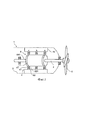
Фиг. 1 является схематическим разрезом обтекателя согласно первому варианту выполнения настоящего изобретения.FIG. 1 is a schematic sectional view of a cowl according to a first embodiment of the present invention.
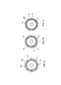
Фиг. 2а - 2с являются схематическими разрезами трех различных вариантов выполнения двигателя в обтекателе фиг. 1.FIG. 2a to 2c are schematic sections of three different engine embodiments in the cowl of FIG. one.
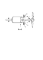
Фиг. 3 является схематическим частичным разрезом части обтекателя согласно другому варианту выполнения настоящего изобретения.FIG. 3 is a schematic partial sectional view of a portion of a cowl according to another embodiment of the present invention.
ПОДРОБНОЕ ОПИСАНИЕ ИЗОБРЕТЕНИЯDETAILED DESCRIPTION OF THE INVENTION
На Фиг. 1 показана часть обтекателя 1 для приведения в движение морского судна в арктических морях, где лопасти 2 винта могут ударять о лед, или о другие твердые объекты, или о дно. Кроме винта, обтекатель 1 содержит жесткий приводной вал 3, соединяющий электрический двигатель 4 с винтом. Двигатель 4 расположен внутри корпуса 5 и содержит ротор 41 и схематически показанный статор 42. Ротор 41 и вал 3 образуют узел, который поддерживается подшипниками. Когда лопасти 2 винта ударяют о лед или о какой-нибудь другой твердый объект, появляется высокая ударная нагрузка, что ведет к мгновенному изгибу узла из ротора и вала, так что ротор 41 может войти в контакт со статором 42 и разрушить двигатель, если не принять меры для предотвращения этого.In FIG. 1 shows a portion of a fairing 1 for propelling a marine vessel in the Arctic seas, where the
Согласно настоящему изобретению, ротор 41 не может войти в разрушительный контакт со статором 42 благодаря тому, что имеются по меньшей мере два элемента 61, 62, которые вместе образуют радиальный подшипник 6 скольжения, имеющий дугообразные сопрягающиеся несущие поверхности 611 и 621, соответственно, которые во время нормальной работы двигателя 4 отделены друг от друга непроводящим промежутком, например газовым промежутком, преимущественно воздушным промежутком, и входят в контакт друг с другом только при кратковременных экстремальных нагрузках. Один из элементов 61, 62 является внутренним элементом 61, имеющим круглую периферию, которая образует одну 611 из несущих поверхностей 611, 621. Дугообразная несущая поверхность 611 внутреннего элемента 61 является соосной с ротором 41 и вращается вместе с ним, и по меньшей мере один из других элементов является внешним элементом 62, который неподвижен относительно статора 42 и имеет дугообразную несущую поверхность 621, соосную с ним.According to the present invention, the
Когда лопасти 2 винта ударяют об обломки льда или другие твердые объекты, и нарастающие кратковременные экстремальные нагрузки изгибают узел из ротора и вала до такой степени, что ротор 41 будет стремиться войти в опасный контакт со статором 42, этот опасный контакт предотвращается благодаря тому, что внутренний элемент 61 радиального подшипника 6 скольжения будет опираться на внешний элемент (элементы) 62.When the blades of the 2 screws hit ice debris or other solid objects, and increasing short-term extreme loads bend the assembly from the rotor and shaft to such an extent that the
Радиальный подшипник 6 скольжения может быть расположен в любом месте вдоль оси узла из вала и ротора (между положениями а и с на фиг. 1), но с учетом удобства обслуживания лучше расположить его на конце двигателя 4. Обычно, предпочтительно расположить его на конце, ближайшем к винту (в положении а на фиг. 1), где также изгиб вала будет максимальным. В случае когда нагрузка является не изгибающей, но ударной, может быть предпочтительным обеспечить два радиальных подшипника скольжения, расположенных в положениях а и с на фиг. 1.The radial sliding bearing 6 can be located anywhere along the axis of the shaft and rotor assembly (between positions a and c in Fig. 1), but taking into account the ease of maintenance, it is better to place it at the end of the
Предпочтительно, один из указанных по меньшей мере двух элементов 61, 62 состоит из более мягкого материала, чем другой, и более мягкий материал является неэлектропроводным. Таким образом, когда несущие поверхности 611 и 621 находятся в контакте друг с другом, проводящий материал не сможет отделиться от более мягкой несущей поверхности и распространиться внутри обтекателя 1, где это могло бы принести вред двигателю 4 или другим компонентам.Preferably, one of said at least two
Более мягкий материал предпочтительно используется для внешнего элемента (элементов) 62. Статор 42 включает обмотки 421, и сегменты 622 из более мягкого материала расположены между обмотками 421 статора 42, как показано на фиг. 2а, или поверх обмоток 421 статора 42, как показано на фиг. 2b. В альтернативном случае более мягкий материал размещают в виде круговой полосы 623 на внутренней поверхности статора 42, как показано на фиг. 2с. Тогда радиальный подшипник 6 скольжения образован двумя полными кольцами 61 и 623, вместо кольца 61 и нескольких сегментов 62 кольца.A softer material is preferably used for the outer element (s) 62. The
В качестве другой альтернативы, не показанной на чертежах, элемент 62 из более мягкого материала крепится к корпусу 5 обтекателя.As another alternative, not shown in the drawings, a
Понятно, что когда один 62 из указанных по меньшей мере двух элементов 61, 62 состоит из более мягкого материала, другой один 61 из этих указанных элементов состоит из более твердого материала. Предпочтительно, более твердый материал используется для внутреннего элемента 61, и внутренний элемент является кольцом 61.It is understood that when one 62 of said at least two
Предпочтительно, ротор 41 имеет обмотки 411, и кольцо 61 из более твердого материала либо размещено поверх обмоток 411 ротора 41, либо является неотъемлемой частью ротора 41, либо кольцом (или двумя, или более), расположенным на конце ротора.Preferably, the
В альтернативном случае кольцо 61 из более твердого материала является специальным устройством двигателя 4 или вала 3, предназначенным для другой главной цели, таким как тормозной диск, как показано на фиг. 3. Кольцо 61 может быть сплошным диском или кольцом, прикрепленным к валу 3, посредством спиц и т.п. Внешний элемент 62 может быть неподвижно прикреплен к неподвижной части двигателя 4, например, образуя внутреннюю поверхность части корпуса (не показано), или прикреплен к корпусу обтекателя (непосредственно или через промежуточные элементы, не показано).Alternatively, the
Кольцо 61 может быть также расположено на периферии фланцевого соединения (не показано) вала 3. При желании, можно поменять кольцо 61 и кольцевые элементы 62 местами, так чтобы кольцевые элементы 62 были расположены на роторе 41, а кольцо 61 - на статоре 42. Также можно, при желании, использовать более твердый материал для несущего элемента (элементов), расположенного на статоре 42, а более мягкий материал - для несущего элемента (элементов), расположенного на роторе 41.The
Вышеприведенное подробное описание, главным образом, предназначено только чтобы помочь пониманию изобретения, и любые не являющиеся необходимыми ограничения не будут интерпретироваться иным образом. Модификации, которые при изучении описания становятся очевидны специалисту, могут быть сделаны без отклонений от идеи изобретения или объема формулы изобретения. Например очевидно, что также могут использоваться несущие элементы из одинакового материала или с одинаковой твердостью. Подобным образом, очевидно, что могут использоваться проводящие элементы, чтобы соответствовать основной функции изобретения.The above detailed description is mainly intended only to help an understanding of the invention, and any unnecessary limitations will not be interpreted otherwise. Modifications that, when studying the description become apparent to a person skilled in the art, can be made without deviating from the idea of the invention or the scope of the claims. For example, it is obvious that load-bearing elements of the same material or with the same hardness can also be used. Similarly, it is obvious that conductive elements can be used to correspond to the main function of the invention.
ПРОМЫШЛЕННАЯ ПРИМЕНИМОСТЬINDUSTRIAL APPLICABILITY
Настоящее изобретение используется для предотвращения опасного контакта между ротором и статором в расположенном в обтекателе двигателе для морских судов, используемых в арктических морях, где винт обтекателя может ударять об обломки льда или о другие твердые объекты, таким образом, создавая удары, которые могут привести к мгновенному изгибу вала обтекателя.The present invention is used to prevent dangerous contact between the rotor and the stator in a fairing engine for marine vessels used in the Arctic seas, where the fairing screw can hit ice debris or other solid objects, thereby creating impacts that can cause instantaneous bending of the fairing shaft.
Claims (22)
Applications Claiming Priority (3)
| Application Number | Priority Date | Filing Date | Title |
|---|---|---|---|
| SE1150824-9 | 2011-09-13 | ||
| SE1150824 | 2011-09-13 | ||
| PCT/SE2012/050951 WO2013039443A1 (en) | 2011-09-13 | 2012-09-10 | A method of and a device for protecting a motor in a pod against shaft bending shocks |
Publications (2)
| Publication Number | Publication Date |
|---|---|
| RU2014111339A RU2014111339A (en) | 2015-10-20 |
| RU2596201C2 true RU2596201C2 (en) | 2016-08-27 |
Family
ID=47883536
Family Applications (1)
| Application Number | Title | Priority Date | Filing Date |
|---|---|---|---|
| RU2014111339/11A RU2596201C2 (en) | 2011-09-13 | 2012-09-10 | Method and device for protection of located in fairing from bending shaft in case |
Country Status (6)
| Country | Link |
|---|---|
| US (1) | US10361605B2 (en) |
| EP (1) | EP2748915B1 (en) |
| CA (1) | CA2847390C (en) |
| NO (1) | NO2748915T3 (en) |
| RU (1) | RU2596201C2 (en) |
| WO (1) | WO2013039443A1 (en) |
Families Citing this family (5)
| Publication number | Priority date | Publication date | Assignee | Title |
|---|---|---|---|---|
| CN104014823A (en) * | 2014-06-24 | 2014-09-03 | 上海大学 | Electric spindle of bidirectional herringbone groove hydrodynamic/hydrostatic integrated gas bearing support |
| EP3069985A1 (en) | 2015-03-20 | 2016-09-21 | ABB Oy | A vessel with a hull and a propulsion unit |
| FR3076115B1 (en) * | 2017-12-22 | 2020-11-20 | Ge Energy Power Conversion Technology Ltd | STATOR INSERTED INSIDE THE CASE |
| CN111237348B (en) * | 2020-01-14 | 2021-07-06 | 上海交通大学 | Small waterplane area catamaran type inverted thrust bearing base and design method thereof |
| DE102020210211A1 (en) | 2020-08-12 | 2022-02-17 | Siemens Mobility GmbH | Arrangement with hollow shaft motor |
Citations (4)
| Publication number | Priority date | Publication date | Assignee | Title |
|---|---|---|---|---|
| SU1687511A1 (en) * | 1989-10-18 | 1991-10-30 | Ленинградский Кораблестроительный Институт | Propulsive complex |
| JPH08196054A (en) * | 1995-01-11 | 1996-07-30 | Shicoh Eng Co Ltd | Cylindrical micro oscillation motor |
| US5798588A (en) * | 1994-04-11 | 1998-08-25 | Sayama Precision Industries Co., Ltd. | Vibrating motor, vibrating motor casing and vibrating device containing vibrating motor |
| JP2000134864A (en) * | 1998-10-22 | 2000-05-12 | Shicoh Eng Co Ltd | Vibration motor |
Family Cites Families (21)
| Publication number | Priority date | Publication date | Assignee | Title |
|---|---|---|---|---|
| US3191079A (en) * | 1960-10-31 | 1965-06-22 | Gen Electric | Heavy dynamoelectric machine having nylon bearings |
| JPS58112894A (en) | 1981-12-25 | 1983-07-05 | Kaiken:Kk | Variable pitch propeller for small vessel |
| GB2268984B (en) * | 1992-07-23 | 1996-04-03 | Glacier Metal Co Ltd | Magnetic bearing back-up |
| US5455470A (en) * | 1994-03-17 | 1995-10-03 | Alliedsignal Inc. | Electrical machines and components thereof incorporating foil journal bearings |
| JPH11182547A (en) * | 1997-12-16 | 1999-07-06 | Meidensha Corp | Rotary electric equipment having magnetic bearing |
| EP1414636B1 (en) * | 2001-08-01 | 2009-12-16 | Sumitomo (SHI) Demag Plastics Machinery GmbH | Electromechanical linear drive |
| GB2378691B (en) * | 2001-08-06 | 2005-12-14 | Alstom | A propulsion unit |
| JP3490074B2 (en) * | 2001-09-17 | 2004-01-26 | 光洋精工株式会社 | Magnetic bearing device |
| US7018249B2 (en) * | 2001-11-29 | 2006-03-28 | Siemens Aktiengesellschaft | Boat propulsion system |
| US6837757B2 (en) * | 2002-04-16 | 2005-01-04 | Electric Boat Corporation | Rim-driven propulsion pod arrangement |
| MXPA06000348A (en) * | 2003-07-10 | 2006-03-28 | Magnetic Applic Inc | Compact high power alternator. |
| US7154191B2 (en) * | 2004-06-30 | 2006-12-26 | General Electric Company | Electrical machine with double-sided rotor |
| DE102004060351A1 (en) * | 2004-12-15 | 2006-07-06 | Siemens Ag | Electric motor for rotation and axial movement |
| US7944074B2 (en) * | 2008-03-25 | 2011-05-17 | General Electric Company | Wind turbine direct drive airgap control method and system |
| DK2108832T3 (en) * | 2008-04-10 | 2016-02-29 | Siemens Ag | Generator and wind turbine |
| DK2157314T4 (en) * | 2008-08-20 | 2019-04-08 | Siemens Ag | Windmill |
| EP2194285A1 (en) * | 2008-12-04 | 2010-06-09 | Hamilton Sundstrand Corporation | Auxiliary rotary bearing system |
| PL2412080T3 (en) | 2009-03-26 | 2018-02-28 | Abb Schweiz Ag | Bearing assembly |
| GB2472279B (en) * | 2009-10-12 | 2011-09-14 | Protean Holdings Corp | Electric motor or generator |
| US8786151B1 (en) * | 2010-12-13 | 2014-07-22 | Northern Power Systems, Inc. | Apparatus for maintaining air-gap spacing in large diameter, low-speed motors and generators |
| ITMI20120257A1 (en) * | 2012-02-21 | 2013-08-22 | Wilic Sarl | ROTARY ELECTRIC MACHINE FOR AEROGENERATOR |
-
2012
- 2012-09-10 US US14/344,524 patent/US10361605B2/en active Active
- 2012-09-10 NO NO12831803A patent/NO2748915T3/no unknown
- 2012-09-10 EP EP12831803.7A patent/EP2748915B1/en active Active
- 2012-09-10 CA CA2847390A patent/CA2847390C/en active Active
- 2012-09-10 RU RU2014111339/11A patent/RU2596201C2/en active
- 2012-09-10 WO PCT/SE2012/050951 patent/WO2013039443A1/en active Application Filing
Patent Citations (4)
| Publication number | Priority date | Publication date | Assignee | Title |
|---|---|---|---|---|
| SU1687511A1 (en) * | 1989-10-18 | 1991-10-30 | Ленинградский Кораблестроительный Институт | Propulsive complex |
| US5798588A (en) * | 1994-04-11 | 1998-08-25 | Sayama Precision Industries Co., Ltd. | Vibrating motor, vibrating motor casing and vibrating device containing vibrating motor |
| JPH08196054A (en) * | 1995-01-11 | 1996-07-30 | Shicoh Eng Co Ltd | Cylindrical micro oscillation motor |
| JP2000134864A (en) * | 1998-10-22 | 2000-05-12 | Shicoh Eng Co Ltd | Vibration motor |
Also Published As
| Publication number | Publication date |
|---|---|
| EP2748915B1 (en) | 2018-03-07 |
| CA2847390A1 (en) | 2013-03-21 |
| EP2748915A4 (en) | 2016-01-06 |
| US10361605B2 (en) | 2019-07-23 |
| EP2748915A1 (en) | 2014-07-02 |
| CA2847390C (en) | 2020-08-04 |
| WO2013039443A1 (en) | 2013-03-21 |
| US20150054367A1 (en) | 2015-02-26 |
| RU2014111339A (en) | 2015-10-20 |
| NO2748915T3 (en) | 2018-08-04 |
Similar Documents
| Publication | Publication Date | Title |
|---|---|---|
| RU2596201C2 (en) | Method and device for protection of located in fairing from bending shaft in case | |
| US8851942B2 (en) | Thrust generating apparatus | |
| Yan et al. | A review of progress and applications of ship shaft-less rim-driven thrusters | |
| JP4203416B2 (en) | Shock resistant marine rotating machinery | |
| JP5384787B2 (en) | Propulsion system for watercraft | |
| AR036382A1 (en) | ELECTRICAL INSTALLATION FOR THE PROPULSION OF A SHIP | |
| KR101185929B1 (en) | Propulsion apparatus for a ship and ship having the same | |
| US20180172019A1 (en) | Rotary machine | |
| RU2674384C1 (en) | Vessel and method applicable therein with hull and propulsion system | |
| JP4005601B2 (en) | Propulsion system layout | |
| US20120141258A1 (en) | Air turbine starter | |
| RU2381136C1 (en) | Ice breaker | |
| PL2238019T3 (en) | Electric engine for a ship | |
| EP3894318A1 (en) | Marine propulsion unit | |
| RU2554506C2 (en) | Propulsion-steering column | |
| TW583118B (en) | Shock-resistant electrical ship-machine, for example, motor or generator | |
| EP2708462A1 (en) | Propulsion device for a floating vessel | |
| RU2741676C1 (en) | Annular ship propulsor | |
| RU2531631C2 (en) | Ring propulsor | |
| US20240051647A1 (en) | Marine propeller | |
| RU203885U1 (en) | Aft end of the hull of an ice-going vessel with a propulsion system | |
| KR101552214B1 (en) | Driving blade structure of ship | |
| EP3992074A1 (en) | Equipment for utilize various types of flange mounted electrical motor variants in self-supporting steerable structure | |
| CN207809738U (en) | Propeller containing double rolling bearing | |
| KR101205939B1 (en) | Propulsion apparatus for ship and Ship including the same |
Legal Events
| Date | Code | Title | Description |
|---|---|---|---|
| PD4A | Correction of name of patent owner |