RU2578072C2 - Asymmetric rotary engine with reverse bias - Google Patents
Asymmetric rotary engine with reverse bias Download PDFInfo
- Publication number
- RU2578072C2 RU2578072C2 RU2011140081/06A RU2011140081A RU2578072C2 RU 2578072 C2 RU2578072 C2 RU 2578072C2 RU 2011140081/06 A RU2011140081/06 A RU 2011140081/06A RU 2011140081 A RU2011140081 A RU 2011140081A RU 2578072 C2 RU2578072 C2 RU 2578072C2
- Authority
- RU
- Russia
- Prior art keywords
- engine
- engine according
- insulated
- front plate
- support plate
- Prior art date
Links
Images
Classifications
-
- F—MECHANICAL ENGINEERING; LIGHTING; HEATING; WEAPONS; BLASTING
- F02—COMBUSTION ENGINES; HOT-GAS OR COMBUSTION-PRODUCT ENGINE PLANTS
- F02B—INTERNAL-COMBUSTION PISTON ENGINES; COMBUSTION ENGINES IN GENERAL
- F02B53/00—Internal-combustion aspects of rotary-piston or oscillating-piston engines
- F02B53/02—Methods of operating
-
- F—MECHANICAL ENGINEERING; LIGHTING; HEATING; WEAPONS; BLASTING
- F01—MACHINES OR ENGINES IN GENERAL; ENGINE PLANTS IN GENERAL; STEAM ENGINES
- F01C—ROTARY-PISTON OR OSCILLATING-PISTON MACHINES OR ENGINES
- F01C1/00—Rotary-piston machines or engines
- F01C1/08—Rotary-piston machines or engines of intermeshing engagement type, i.e. with engagement of co- operating members similar to that of toothed gearing
- F01C1/10—Rotary-piston machines or engines of intermeshing engagement type, i.e. with engagement of co- operating members similar to that of toothed gearing of internal-axis type with the outer member having more teeth or tooth-equivalents, e.g. rollers, than the inner member
- F01C1/104—Rotary-piston machines or engines of intermeshing engagement type, i.e. with engagement of co- operating members similar to that of toothed gearing of internal-axis type with the outer member having more teeth or tooth-equivalents, e.g. rollers, than the inner member one member having simultaneously a rotational movement about its own axis and an orbital movement
-
- F—MECHANICAL ENGINEERING; LIGHTING; HEATING; WEAPONS; BLASTING
- F01—MACHINES OR ENGINES IN GENERAL; ENGINE PLANTS IN GENERAL; STEAM ENGINES
- F01C—ROTARY-PISTON OR OSCILLATING-PISTON MACHINES OR ENGINES
- F01C1/00—Rotary-piston machines or engines
- F01C1/30—Rotary-piston machines or engines having the characteristics covered by two or more groups F01C1/02, F01C1/08, F01C1/22, F01C1/24 or having the characteristics covered by one of these groups together with some other type of movement between co-operating members
- F01C1/40—Rotary-piston machines or engines having the characteristics covered by two or more groups F01C1/02, F01C1/08, F01C1/22, F01C1/24 or having the characteristics covered by one of these groups together with some other type of movement between co-operating members having the movement defined in group F01C1/08 or F01C1/22 and having a hinged member
- F01C1/46—Rotary-piston machines or engines having the characteristics covered by two or more groups F01C1/02, F01C1/08, F01C1/22, F01C1/24 or having the characteristics covered by one of these groups together with some other type of movement between co-operating members having the movement defined in group F01C1/08 or F01C1/22 and having a hinged member with vanes hinged to the outer member
-
- F—MECHANICAL ENGINEERING; LIGHTING; HEATING; WEAPONS; BLASTING
- F04—POSITIVE - DISPLACEMENT MACHINES FOR LIQUIDS; PUMPS FOR LIQUIDS OR ELASTIC FLUIDS
- F04C—ROTARY-PISTON, OR OSCILLATING-PISTON, POSITIVE-DISPLACEMENT MACHINES FOR LIQUIDS; ROTARY-PISTON, OR OSCILLATING-PISTON, POSITIVE-DISPLACEMENT PUMPS
- F04C2250/00—Geometry
- F04C2250/30—Geometry of the stator
- F04C2250/301—Geometry of the stator compression chamber profile defined by a mathematical expression or by parameters
Abstract
Description
ПРЕДПОСЫЛКИ СОЗДАНИЯ НАСТОЯЩЕГО ИЗОБРЕТЕНИЯBACKGROUND OF THE INVENTION
[0002] Патент США №6,758,188 с названием "Асимметричный роторный двигатель с обратным смещением и продолжительным крутящим моментом", который полностью включен в настоящее описание посредством ссылки, раскрывает асимметричный роторный двигатель с обратным смещением, или IDAR (Inverse Displacement Asymmetric Rotary) двигатель. Этот двигатель включает стенку внутренней камеры, стенку внешней камеры и подвижный профильный элемент, определяемый следующим описанием.[0002] US Patent No. 6,758,188, entitled "Asymmetric Rotary Motor with Reverse Bias and Continuous Torque", which is incorporated herein by reference in its entirety, discloses an asymmetric reverse bias motor or IDAR (Inverse Displacement Asymmetric Rotary) motor. This engine includes the wall of the inner chamber, the wall of the outer chamber and a movable profile element, defined by the following description.
[0003] Крутящий момент может быть достигнут по всему такту сгорания посредством выполнения камеры в роторным двигателе таким образом, чтобы угол установки между направлением силы от изогнутого профильного элемента и направлением силы стенки внешней камеры в каждой точке вдоль стенки внешней камеры в течение такта сгорания представлял собой угол более 0 градусов и менее 90 градусов. Форма стенки внутренней камеры, стенки внешней камеры и изогнутого профильного элемента, которая способствует тому, чтобы угол установки был между 0 градусов и 90 градусов, может быть определена алгебраически относительно заданного угла установки.[0003] Torque can be achieved throughout the combustion cycle by executing the chamber in a rotary engine so that the installation angle between the direction of force from the curved profile element and the direction of the wall force of the outer chamber at each point along the wall of the outer chamber during the combustion cycle is an angle of more than 0 degrees and less than 90 degrees. The shape of the wall of the inner chamber, the wall of the outer chamber and the curved profile element, which helps to ensure that the installation angle is between 0 degrees and 90 degrees, can be determined algebraically relative to a given installation angle.
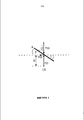
[0004] Как показано на фиг. 1, где S представляет поверхность стенки камеры, a CS представляет коленчатый вал, величина крутящего момента, создаваемого заданным углом установки С, который обеспечивается силой F(r), взаимодействующей с поверхностью, может быть равной F(r) ∗ расстояние D∗cos(C)∗sin (С). Как может быть определено математически, крутящий момент имеет максимальную величину, когда угол установки С равен 45 градусов. Величина косинус ∗ синус для 45 градусов равна 0,5. Другие углы установки между примерно 20 градусами и примерно 70 градусами могут создавать подходящие величины крутящего момента.[0004] As shown in FIG. 1, where S represents the surface of the chamber wall, and CS represents the crankshaft, the magnitude of the torque created by the given installation angle C, which is provided by the force F (r) interacting with the surface, can be equal to F (r) ∗ distance D ∗ cos ( C) ∗ sin (C). As can be determined mathematically, the torque has a maximum value when the installation angle C is 45 degrees. The cosine ∗ sine for 45 degrees is 0.5. Other mounting angles between about 20 degrees and about 70 degrees can create suitable torque values.
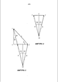
[0005] Как показано на фиг. 2, если радиус R удерживался постоянным при вращении по некоторому углу D вокруг точки CS, касательная к дуге, описываемая радиусом R, определит прямую линию между точками X и Z. Касательная образует прямой угол относительно радиуса в центре дуги (угол D/2). Если линия X-Z также опишет поверхность камеры, против которой проталкивался радиус, при угле D/2, то угол установки между направлением силы от радиуса и направлением силы от поверхности, будет равным 0.[0005] As shown in FIG. 2, if the radius R was kept constant while rotating along a certain angle D around the point CS, the tangent to the arc described by the radius R will determine a straight line between points X and Z. The tangent forms a right angle relative to the radius at the center of the arc (angle D / 2). If the X-Z line also describes the surface of the chamber against which the radius was pushed, at an angle D / 2, then the installation angle between the direction of the force from the radius and the direction of the force from the surface will be 0.
[0006] Это отношение описывает условие в стандартной технологии роторного двигателя, в которой угол установки составляет 0 в начале и конце такта сгорания. Для достижения крутящего момента в течение всего такта сгорания, угол установки может быть между 0 и 90 градусами в каждой точке в течение такта сгорания.[0006] This relationship describes a condition in standard rotary engine technology in which the installation angle is 0 at the beginning and end of a combustion stroke. To achieve torque throughout the entire combustion cycle, the installation angle can be between 0 and 90 degrees at each point during the combustion cycle.
[0007] Фиг. 3 иллюстрирует касательную С между точками Y и Z к дуге, формируемой вращением изменяющегося радиуса по некоторому углу D вокруг фиксированной точки CS. Если касательная С представляет собой поверхность, против которой проталкивается изменяющийся радиус, то угол установки между направлением силы от радиуса и направлением силы от поверхности будет углом Е, представляющим некоторый угол между 0 и 90 градусами.[0007] FIG. 3 illustrates tangent C between points Y and Z to an arc formed by rotating a varying radius at a certain angle D around a fixed point CS. If tangent C is the surface against which the changing radius is pushed, then the angle of installation between the direction of the force from the radius and the direction of the force from the surface will be an angle E representing a certain angle between 0 and 90 degrees.
[0008] Длина изменяющегося радиуса в любой заданной точке на фиг. 3 может быть равной R+dR, где R это начальная длина радиуса, dR это переменная длина, равная или большая, чем 0. Если величины R и dR известны на протяжении угла D, то угол установки Е может быть вычислен. И наоборот, если угол установки Е известен для средней точки D/2 некоторого угла вращения D, то может быть определена длина dR.[0008] The length of the varying radius at any given point in FIG. 3 can be equal to R + dR, where R is the initial length of the radius, dR is a variable length equal to or greater than 0. If the values of R and dR are known over the angle D, then the installation angle E can be calculated. Conversely, if the installation angle E is known for the midpoint D / 2 of a certain rotation angle D, then the length dR can be determined.
[0009] Может быть выведена математическая формула для кривой, причем радиус кривой составляет угол установки больше 0 градусов и меньше 90 градусов с поверхностью в каждой точки вдоль кривой при вращении радиуса вокруг фиксированной точки начала отчета для вращения. Угол установки может быть между примерно 20 градусами и примерно 70 градусами в каждой точке вдоль кривой. Может быть использована математическая формула для получения кривой, которая может быть профилем подвижного профильного элемента и частью неподвижной стенки внутренней камеры IDAR двигателя.[0009] A mathematical formula can be derived for the curve, the radius of the curve being an angle of installation greater than 0 degrees and less than 90 degrees with the surface at each point along the curve when the radius is rotated around a fixed starting point for the report to rotate. The installation angle can be between about 20 degrees and about 70 degrees at each point along the curve. A mathematical formula can be used to obtain a curve, which can be the profile of the movable profile element and part of the fixed wall of the IDAR internal chamber of the engine.
[0010] Также со ссылкой на фиг. 3, заданный угол установки Е может быть использован для вычисления величины dR, на которую радиус R должен увеличиться для сохранения угла установки Е, когда радиус (R+dR) вращается вокруг коленчатого вала. Для угла установки Е в 45 градусов треугольник XYZ на фиг. 3 имеет стороны XY и XZ равной длины. Далее приведены формулы для определения изменения радиуса dR относительно радиуса R, необходимые для формирования угла установки Е в 45 градусов:[0010] Also with reference to FIG. 3, a predetermined installation angle E can be used to calculate the value of dR by which the radius R must increase to maintain the installation angle E when the radius (R + dR) rotates around the crankshaft. For an angle of installation E of 45 degrees, the triangle XYZ in FIG. 3 has sides XY and XZ of equal length. The following are formulas for determining the change in radius dR relative to radius R, necessary to form the installation angle E at 45 degrees:
![]()
![]()
![]()
![]()
![]()
![]()
[0014] Формула (6) показывает, что для заданного угла вращения D, например, в 1 градус, радиус R должен меняться с определенной долей, равной длине dR. Доля, на которую должен меняться R, а именно dR/R, постоянна для сохранения постоянного угла установки Е в 45 градусов на протяжении некоторого угла вращения D. Относительное изменение может быть увеличением по длине. Например, используя формулу (6), для формирования угла установки в 45 градусов при вращении в 1 градус радиус R может быть увеличен примерно на 1, 76%. Долю, с которой меняется R (dR), может оставаться постоянной независимо от начального значения R для каждого градуса вращения.[0014] Formula (6) shows that for a given rotation angle D, for example, of 1 degree, the radius R should change with a certain fraction equal to the length dR. The fraction by which R is to be changed, namely dR / R, is constant in order to maintain a constant installation angle E of 45 degrees over a certain rotation angle D. The relative change can be an increase in length. For example, using formula (6), to form an installation angle of 45 degrees with a rotation of 1 degree, the radius R can be increased by about 1, 76%. The fraction with which R (dR) changes can remain constant regardless of the initial value of R for each degree of rotation.
[0015] Общая формула для углов, отличных от 45 градусов, может быть выведена умножением правой стороны формулы (6) на коэффициент пересчета K, который характеризует различие длины стороны XY треугольника XYZ от длины стороны XZ, когда величина угла установки Е изменена с 45 градусов, причем длины XY и XZ равны. Когда угол установки Е не равен 45 градусам, формулы имеет следующий вид:[0015] The general formula for angles other than 45 degrees can be derived by multiplying the right side of formula (6) by a conversion factor K, which characterizes the difference in the length of the XY side of the triangle XYZ from the length of the XZ side when the installation angle E is changed from 45 degrees , and the lengths XY and XZ are equal. When the installation angle E is not equal to 45 degrees, the formula has the following form:
![]()
![]()
[0017] Коэффициент пересчета K равен 1/tan(E). Когда угол Е равен (45) градусам, 1/tan(45)=1, откуда получается формула (6). Когда угол Е не равен (45) градусам, K имеет величину, отличную от 1. Формула (8) может быть использована для вычисления, на долю должен измениться R при величине вращения D для формирования заданного угла установки Е.[0017] The conversion factor K is 1 / tan (E). When the angle E is equal to (45) degrees, 1 / tan (45) = 1, whence formula (6) is obtained. When the angle E is not equal to (45) degrees, K has a value other than 1. Formula (8) can be used for calculation, R must change by the fraction at the rotation value D to form the given installation angle E.
[0018] Кривая согласно формуле (6) или (8) при использовании постоянного угла установки Е может быстро спиралеобразно выдаваться в сторону от фиксированной точки вращения. Для менее выраженной спиралеобразности с меньшей долей изменения по радиусу может быть использован изменяющийся угол установки Е. Например, угол установки в начале кривой может быть 45 градусов или больше и менее 90 градусов и может постепенно уменьшаться при вращении R вокруг фиксированной точки. Изменяющийся угол установки, например, непрерывно уменьшающийся угол установки, может поддерживаться между 90 градусами и 0 градусов, или между 70 градусами и 0 градусов.[0018] A curve according to formula (6) or (8), when using a constant installation angle E, can quickly project out in a spiral manner away from a fixed pivot point. For less pronounced spirality with a smaller degree of change in radius, a variable installation angle E can be used. For example, the installation angle at the beginning of the curve can be 45 degrees or more and less than 90 degrees and can gradually decrease when R rotates around a fixed point. A changing installation angle, for example, a continuously decreasing installation angle, can be maintained between 90 degrees and 0 degrees, or between 70 degrees and 0 degrees.
[0019] Обращаясь к формуле (2) и со ссылкой на фиг. 3, можно увидеть, что элемент dR∗sin(D/2) определяет очень небольшую величину относительно других элементов формулы. Если вычесть, а не прибавлять, элемент dR∗sin(D/2) из 2∗R∗sin (D/2), то величина радиуса R все также будет увеличиваться, но более постепенно, а угол установки Е будет постепенно уменьшаться. Вычитая dR∗sin(D/2) из 2∗R∗sin (D/2) и применяя коэффициент пересчета К для начального угла падения более 45 градусов, можно получить следующую формулу:[0019] Referring to formula (2) and with reference to FIG. 3, it can be seen that the element dR ∗ sin (D / 2) determines a very small value relative to other elements of the formula. If we subtract, and not add, the element dR ∗ sin (D / 2) from 2 ∗ R ∗ sin (D / 2), then the value of the radius R will also increase, but more gradually, and the installation angle E will gradually decrease. Subtracting dR ∗ sin (D / 2) from 2 ∗ R ∗ sin (D / 2) and applying the conversion factor K for the initial incidence angle of more than 45 degrees, we can obtain the following formula:
![]()
![]()
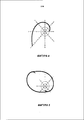
[0021] Используя формулу (10) с начальной длиной радиуса R в (2) и начальным углом установки в 45 градусов, К будет равен 1, и будет сформирована кривая, показанная на фиг. 4.[0021] Using formula (10) with an initial radius length R in (2) and an initial installation angle of 45 degrees, K will be 1, and the curve shown in FIG. four.
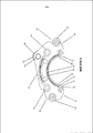
[0022] На фиг. 4 показана примерная кривая, сформированная при помощи формулы (10), а также график двух окружностей, одна с радиусом в 1 единицу, и одна с радиусом в 2 единицы. Также со ссылкой на фиг. 4, линия, изображенная от начала касательной в любой точке кривой, сформированной в соответствии с формулой (10), будет иметь угол установки в 45 градусов при 0 градусов вращения, а угол установки будет постепенно уменьшаться до примерно 20 градусов при 90 градусах вращения.[0022] FIG. 4 shows an exemplary curve generated using formula (10), as well as a graph of two circles, one with a radius of 1 unit, and one with a radius of 2 units. Also with reference to FIG. 4, the line drawn from the beginning of the tangent at any point in the curve formed in accordance with formula (10) will have an installation angle of 45 degrees at 0 degrees of rotation, and the installation angle will gradually decrease to about 20 degrees at 90 degrees of rotation.
[0023] Может быть сформирована стенка внутренней камеры IDAR двигателя, имеющей контур кривой по фиг. 4, что даст в результате угол установки с изогнутым контуром, начинающимся при 45 градусах при 0 градусах вращения, который постепенно уменьшается до 20 градусов при 90 градусах вращения. Поскольку контур стенки внешней камеры IDAR двигателя может быть функцией от контура стенки внутренней камеры, угол установки между направлением компоненты генерирующего силу крутящего момента от изогнутого контура и силой от стенки внешней камеры также меняется от 45 градусов примерно до 20 градусов в течение такта сгорания.[0023] A wall of an internal engine IDAR chamber having the curve outline of FIG. 4, which will result in an installation angle with a curved contour starting at 45 degrees at 0 degrees of rotation, which gradually decreases to 20 degrees at 90 degrees of rotation. Since the wall contour of the external IDAR chamber of the engine can be a function of the contour of the wall of the inner chamber, the installation angle between the direction of the component generating the torque force from the curved contour and the force from the wall of the outer chamber also changes from 45 degrees to about 20 degrees during the combustion cycle.
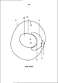
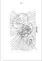
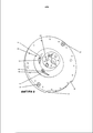
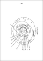
[0024] Для формирования контура стенки внутренней камеры кривая, формируемая формулой (10), например, кривой, показанной на фиг. 4, может быть продублирована с вращением на 180 градусов для формирования двух пересекающихся кривых одинаковой формы, как показано на фиг. 5. Форма, образованная на фиг. 5, может определять стенку внутренней камеры IDAR двигателя и изолированный элемент, вокруг которого может вращаться изогнутый профильный элемент IDAR двигателя в пределах камеры IDAR двигателя. Точка начала кривой, образованной формулой (10), может быть местом расположения коленчатого вала в пределах указанного изолированного элемента IDAR двигателя. Как показано на фиг. 5, коленчатый вал может быть смещен в пределах указанного изолированного элемента IDAR двигателя. Может быть сформирован профильный элемент, сопрягаемый с формой стенки внутренней камеры, как показано на фиг. 6.[0024] To form the contour of the wall of the inner chamber, a curve formed by formula (10), for example, the curve shown in FIG. 4 can be duplicated 180 degrees to form two intersecting curves of the same shape, as shown in FIG. 5. The mold formed in FIG. 5 may define the wall of the internal engine IDAR chamber and an insulated member around which the curved IDAR profile member of the engine can rotate within the engine IDAR. The start point of the curve formed by formula (10) may be the location of the crankshaft within the specified insulated IDAR element of the engine. As shown in FIG. 5, the crankshaft can be offset within the specified insulated IDAR element of the engine. A profile element mating with the wall shape of the inner chamber may be formed, as shown in FIG. 6.
[0025] Камера 2 и изогнутый профильный элемент 4, как представлено на фиг. 6 в качестве примера, могут иметь кривошипный центральный элемент 6 и фиксатор 8, смещенные относительно центра внутренней кривой 10. Положение кривошипного центрального элемента 6 и фиксатора 8 может быть смещено в направлении одной стороны профильного элемента, если сравнивать с геометрическим центром контура.[0025] The
[0026] Форма стенки 14 внешнего контура может быть образована перемещением изогнутого контура вокруг стенки внутреннего контура. Стенка внешнего контура может быть выполнена так, чтобы удерживать изогнутый профильный элемент у стенки внутреннего контура, в то время как фиксатор или внешняя кривая изогнутого контура перемещается вдоль стенки внешней камеры. Соответственно, фиг. 6 изображает, что в пределах камеры 2 определены относительно кривой, формируемой по формуле (10) контуры и/или положения стенки 16 внутренней камеры, изолированный элемент 18, коленчатый вал 12, стенка 14 внешней камеры, изогнутый профильный элемент 4, кривошипный центральный элемент 6 и фиксатор 8.[0026] The shape of the
[0027] Касательно вида фиг. 6 следует отметить, что форма стенки 14 внешней камеры может быть получена из тех же математических функций, что и стенка 16 внутренней камеры. Стенка 14 внешней камеры может иметь ту же форму, что и по меньшей мере часть стенки 16 внутренней камеры, но большую по масштабу и повернутую на некоторый угол, например, 90 градусов, вокруг начала в пределах части камеры 2, что соответствует такту сгорания.[0027] Regarding the view of FIG. 6 it should be noted that the shape of the
[0028] Описанная выше технология IDAR двигателя имеет множество преимуществ над технологией стандартного поршневого двигателя внутреннего сгорания. Некоторые из преимуществ, обеспечиваемых конфигурацией IDAR двигателя, относятся к длинам тактов различного размера.[0028] The IDAR engine technology described above has many advantages over standard piston internal combustion engine technology. Some of the benefits provided by the IDAR configuration of the engine relate to clock sizes of various sizes.
[0029] Например, такт сжатия может происходить при более короткой величине хода, чем такт расширения (сгорания). Это позволяет произвести больше работы в течение более длинного такт расширения при сравнении с поршневой технологией такого же перемещения.[0029] For example, a compression stroke may occur at a shorter stroke rate than an expansion (combustion) stroke. This allows you to do more work over a longer expansion stroke when compared with piston technology of the same movement.
[0030] Аналогичным образом, такты выпуска и впуска также не должны быть одинаковой длины. Такт расширения IDAR двигателя также имеет функцию механической передачи в работу, которая почти непрерывна, вместо передаточной функции поршневой технологии, имеющей форму кривой нормального распределения. Это осуществляется в виде кривой крутящего момента, имеющей очень ровную форму с небольшим колебанием в диапазоне частот вращения. Это происходит частично по той причине, что длина плеча кривошипа в сущности возрастает при протекании такта расширения.[0030] Similarly, the exhaust and intake strokes also need not be the same length. The expansion stroke of the IDAR engine also has a mechanical transfer function to operation, which is almost continuous, instead of the transfer function of the piston technology, which has the shape of a normal distribution curve. This is carried out in the form of a torque curve, which has a very even shape with a slight fluctuation in the speed range. This is partly due to the fact that the crank arm length in essence increases with the expansion stroke.
[0031] Кроме того, все четыре такта двигателя: впуск, сжатие, сгорание и выпуск, могут иметь различную длительность и различную величину и могут происходить при различных скоростях в пределах той же четырех ходовой[0031] In addition, all four engine strokes: intake, compression, combustion, and exhaust, can have different durations and sizes and can occur at different speeds within the same four-way
последовательности. Это позволяет конструкторам IDAR двигателя оптимизировать работу двигателя и уменьшить побочные продукты, относящиеся к загрязнению, способом, превосходящим технологию поршневого двигателя.sequence. This allows IDAR engine designers to optimize engine performance and reduce by-products related to fouling in a way superior to piston engine technology.
[0032] Дополнительно необходимо отметить, все четыре такта протекают в пределах одного полного вращения вала. IDAR двигатель функционирует до некоторой степени как двухтактный двигатель исходя из того, что он имеет очень большую величину ускорения, но, в тоже время, он обладает параметрами генерации крутящего момента, присущими длинноходовому дизельному двигателю сходного смещения. Конфигурация IDAR двигателя не должна быть сгруппирована в подкатегории по функционированию на основе отношений диаметра отверстий к растяжению мембраны, как это делается в случае поршневой технологии, поскольку IDAR технология охватывает все эти категории, когда делаются сходные сравнения.[0032] Additionally, it should be noted that all four clock cycles occur within one full rotation of the shaft. The IDAR engine functions to some extent as a two-stroke engine based on the fact that it has a very large acceleration value, but at the same time, it possesses the torque generation parameters inherent in a long-stroke diesel engine of similar displacement. The configuration of an IDAR engine should not be grouped into a subcategory for operation based on the ratio of bore diameter to membrane elongation, as is the case with piston technology, since IDAR technology covers all of these categories when similar comparisons are made.
[0033] При фактическом производстве IDAR двигателя имеют место сложные кривые и плоские поверхности. Однако герметизирующие элементы всегда осуществляют изолирование у поверхности, которая является плоской, и ориентированы в направлении длины материала герметизирующего элемента. Это означает, что критическим производственным размером является плоскостность поверхностей частей и способность выравнивать части, так что противоположные стороны параллельны по всей ширине двигателя. Также важно, чтобы части не отклонялись в направлении траектории движения и чтобы поверхности, которые начинаются перпендикулярно друг другу, оставались такими в течение такта сгорания.[0033] In the actual production of an IDAR engine, complex curves and flat surfaces occur. However, the sealing elements always insulate at a surface that is flat and oriented in the length direction of the material of the sealing element. This means that the critical manufacturing dimension is the flatness of the surfaces of the parts and the ability to align the parts, so that the opposite sides are parallel across the entire width of the engine. It is also important that the parts do not deviate in the direction of the motion path and that surfaces that start perpendicular to each other remain so during the combustion cycle.
[0034] Поскольку длины тактов, величины и скорости могут отличаться друг от друга и не являются симметричными, как в технологии поршневого двигателя, важно иметь хорошее управление потоком входного отверстия при впуске и выпуске. Это позволяет добиться стандартов функционирования, превосходящих возможности технологии поршневого двигателя.[0034] Since the cycle lengths, values, and speeds may differ from each other and are not symmetrical, as in piston engine technology, it is important to have good control of the flow of the inlet at the inlet and outlet. This allows us to achieve performance standards that exceed the capabilities of piston engine technology.
[0035] Кроме того, поскольку IDAR двигатель имеет уникальный ход расширения, указанная конфигурация сводится к базовой конструкции силовой установки на основе только хода расширения IDAR двигателя. Когда IDAR двигатель соединен с внешним устройством, он формирует внешний двигатель внутреннего сгорания или силовую установку, приводимую в действие какой-то другой движущей силой, такой как сжатый воздух.[0035] In addition, since the IDAR engine has a unique expansion stroke, this configuration is reduced to the basic design of the power plant based only on the expansion stroke of the IDAR engine. When the IDAR engine is connected to an external device, it forms an external internal combustion engine or power plant driven by some other driving force, such as compressed air.
[0036] Задачей настоящего изобретения является разработка усовершенствований контроля и эффективности IDAR технологии, а также облегчение производства и расширение использования IDAR технологии.[0036] An object of the present invention is to provide improvements in the control and effectiveness of IDAR technology, as well as facilitating the production and expansion of the use of IDAR technology.
ОСУЩЕСТВЛЕНИЕ ИЗОБРЕТЕНИЯDETAILED DESCRIPTION OF THE INVENTION
[0037] Предложен асимметричный роторный двигатель с обратным смещением, содержащий камеру. Камера в свою очередь содержит неподвижный изолированный элемент, имеющую внешнюю поверхность, которая представляет собой удлиненную выпуклую форму. Изолированный элемент включает канал коленчатого вала, расположенный на расстоянии от центра указанного изолированного элемента. Камера включает также переднюю пластину, присоединенную к передней поверхности указанного изолированного элемента, подвижный профильный элемент с вогнутой формой, смещенный в направлении внешней поверхности изолированного элемента и выполненный с возможностью вращения вокруг изолированного элемента, рабочий объем, заданный между внутренней поверхностью профильного элемента (контура) и внешней поверхностью изолированного элемента, и по меньше мере один взаимодействующий с передней пластиной подшипник, проходящий от передней поверхности подвижного профильного элемента и над направляющими краем передней пластины. Взаимодействующий с передней пластиной подшипник выполнен с возможностью взаимодействия с указанным направляющим краем во время такта сгорания.[0037] An asymmetric reverse bias rotary engine comprising a chamber is provided. The camera, in turn, contains a stationary insulated element having an outer surface, which is an elongated convex shape. The insulated element includes a crankshaft channel located at a distance from the center of the specified insulated element. The camera also includes a front plate attached to the front surface of the specified insulated element, a movable profile element with a concave shape, offset in the direction of the outer surface of the insulated element and made to rotate around the insulated element, the working volume defined between the inner surface of the profile element (circuit) and the outer surface of the insulated element, and at least one bearing interacting with the front plate passing from the front NOSTA movable profiled element and on the guide edge of the front plate. The bearing interacting with the front plate is adapted to interact with said guide edge during a combustion stroke.
В частных вариантах выполнения изобретения:In private embodiments of the invention:
- профильный элемент включает два взаимодействующих с передней пластиной подшипника, расположенных на соответствующих противоположных периферических краях профильного элемента,- the profile element includes two interacting with the front plate of the bearing located on the respective opposite peripheral edges of the profile element,
- два указанных подшипника содержат подшипник ведущего края и подшипник заднего края, причем один из подшипников проходит дальше от передней поверхности подвижного профильного элемента, чем другой подшипник, а передняя пластина содержит два направляющих края с различными профилями, при этом первый из направляющих краев контактирует с одним из подшипников, а второй из направляющих краев - с другим из указанных подшипников.- two of these bearings contain a leading edge bearing and a rear edge bearing, one of the bearings extending further from the front surface of the movable profile element than the other bearing, and the front plate contains two guide edges with different profiles, while the first of the guide edges is in contact with one of bearings, and the second of the guide edges with the other of these bearings.
- камера дополнительно содержит обод с внутренней поверхностью, причем по меньшей мере часть изолированного элемента и профильного элемента расположены в пределах внутренней поверхности обода, подшипник для взаимодействия с внутренней поверхностью обода, проходящий от внешней поверхности подвижного профильного элемента, причем внутренняя поверхность обода имеет такую форму, чтобы смещать профильный элемент в направлении изолированного элемента, посредством чего взаимодействующий с передней пластиной подшипник взаимодействует с направляющим краем.- the camera further comprises a rim with an inner surface, and at least a portion of the insulated element and the profile element are located within the inner surface of the rim, a bearing for interacting with the inner surface of the rim extending from the outer surface of the movable profile element, and the inner surface of the rim has such a shape, in order to bias the profile element towards the insulated element, whereby the bearing interacting with the front plate interacts with directs edge.
- двигатель дополнительно содержит опорную пластину, включающую отверстие впуска и отверстие выпуска, причем отверстие выпуска имеет дугообразную форму, заданную по меньшей мере частично проекцией профильного элемента на опорную пластину, когда рабочий объем находится в такте выпуска.- the engine further comprises a support plate including an inlet opening and an outlet opening, wherein the outlet opening has an arcuate shape defined at least partially by the projection of the profile element onto the support plate when the displacement is in the exhaust stroke.
- отверстие впуска имеет дугообразную форму, заданную по меньшей мере частично проекцией профильного элемента на опорную пластину, когда рабочий объем находится в такте впуска,- the inlet opening has an arcuate shape defined at least partially by the projection of the profile element onto the support plate when the displacement is in the inlet stroke,
- в пластине выполнено два упомянутых отверстия впуска и два упомянутых отверстия выпуска, причем отверстия впуска и выпуска выполнены у периферийных краев изолированного элемента на противоположных сторонах,- in the plate there are two said inlet openings and two mentioned outlet openings, the inlet and outlet openings being made at the peripheral edges of the insulated element on opposite sides,
- двигатель является приводимым в действие сжатым воздухом,- the engine is driven by compressed air,
- отверстия впуска выполнены с обеспечением возможности управления потоком горючего вещества,- inlet openings are made with the possibility of controlling the flow of combustible matter,
- опорная пластина соединена с дополнительной опорной пластиной, при этом в дополнительной опорной пластине выполнены отверстия впуска,- the support plate is connected to the additional support plate, while the inlet holes are made in the additional support plate,
- подвижный профильный элемент дополнительно содержит боковые герметизирующие элементы, взаимодействующие с поверхностями передней пластины и опорной пластины, и герметизирующие элементы верхней части, расположенные на периферийной поверхности профильного элемента и взаимодействующие с поверхностями изолированного элемента и передней пластины.- the movable profile element further comprises lateral sealing elements interacting with the surfaces of the front plate and the support plate, and sealing elements of the upper part located on the peripheral surface of the profile element and interacting with the surfaces of the insulated element and the front plate.
- герметизирующие элементы верхней части выполнены из чугуна,- sealing elements of the upper part are made of cast iron,
- опорная пластина включает отверстие для размещения свечи зажигания, расположенное в области, в которой происходит такт сжатия,- the support plate includes an opening for the placement of the spark plug, located in the area in which the compression stroke occurs,
- подвижный профильный элемент включает отверстие для размещения свечи зажигания, выходящее на внутреннюю поверхность профильного элемента таким образом, что электроды свечи зажигания входят в рабочий объем.- the movable profile element includes a hole for accommodating the spark plug, extending to the inner surface of the profile element so that the electrodes of the spark plug are included in the working volume.
- двигатель включает клапанный канал, выполненный в изолированном элементе, и- the engine includes a valve channel made in an insulated element, and
цилиндрический щелевой клапан, установленный с возможностью вращения в клапанном канале таким образом, что горючее вещество выборочно доставляется в рабочий объем,a cylindrical slotted valve mounted rotatably in the valve channel so that the combustible substance is selectively delivered to the working volume,
- цилиндрический щелевой клапан включает зубчатый диск, который выполнен с возможностью зацепления прямо или опосредованно с коленчатым валом в канале коленчатого вала, посредством чего ход профильного элемента в камере обеспечивает поворот цилиндрического щелевого клапана для выборочной доставки горючего вещества в рабочий объем,- the cylindrical slit valve includes a gear disk, which is adapted to engage directly or indirectly with the crankshaft in the channel of the crankshaft, whereby the stroke of the profile element in the chamber rotates the cylindrical slit valve for selectively delivering combustible material to the working volume,
- двигатель включает клапанное отверстие в изолированном элементе и вращающийся клапан, установленный с возможностью вращения в указанном клапанном отверстии с обеспечением открытия и закрытия отверстия впуска,- the engine includes a valve hole in the insulated element and a rotary valve mounted to rotate in the specified valve hole with the opening and closing of the inlet opening,
- вращающийся клапан включает диск, имеющий отверстия, расположенный напротив поверхности опорной пластины с обеспечением перекрытия поверхностью диска отверстия впуска,- the rotary valve includes a disk having holes located opposite the surface of the base plate to ensure that the surface of the disk overlaps the inlet openings,
- вращающийся клапан включает зубчатый диск, который выполнен с возможностью зацепления прямо или опосредованно с коленчатым валом в канале коленчатого вала, посредством чего ход профильного элемента в камере обеспечивает поворот вращающегося клапана с обеспечением открытия и закрытия отверстия впуска,- the rotary valve includes a gear disk, which is adapted to engage directly or indirectly with the crankshaft in the channel of the crankshaft, whereby the stroke of the profile element in the chamber rotates the rotary valve to ensure opening and closing of the inlet opening,
- профильный элемент включает рециркуляционное отверстие для обеспечения рециркуляции отработавшего газа,- the profile element includes a recirculation hole for providing exhaust gas recirculation,
- двигатель включает управляющий клапан, расположенный в отверстии выпуска на опорной пластины для герметизации отверстия выпуска, за исключением случая нахождения двигателя в такте выпуска,- the engine includes a control valve located in the outlet on the base plate to seal the outlet, except when the engine is in the exhaust stroke,
- управляющий клапан представляет собой лепестковый клапан,- the control valve is a flap valve,
- управляющий клапан представляет собой вращающийся клапан,- the control valve is a rotary valve,
- двигатель содержит подвижные профильные элементы.- the engine contains movable profile elements.
- поверхность опорной пластины и внешняя поверхность обода имеют одинаковую форму.- the surface of the base plate and the outer surface of the rim have the same shape.
КРАТКОЕ ОПИСАНИЕ ЧЕРТЕЖЕЙBRIEF DESCRIPTION OF THE DRAWINGS
[0038] Необходимо отметить, что следующие чертежи изображают особенности только вариантов реализации изобретения, и поэтому они не должны рассматриваться как ограничивающие объем изобретения.[0038] It should be noted that the following drawings depict features of only embodiments of the invention, and therefore should not be construed as limiting the scope of the invention.
[0039] Фиг. 1 представляет взаимное расположение силы F(s) стены и силы F(r) ротора, когда сила ротора и составляющие силы стены находятся на одной прямой.[0039] FIG. 1 represents the relative position of the wall force F (s) and the rotor force F (r) when the rotor force and the component wall forces are on the same line.
[0040] Фиг. 2 представляет взаимное расположение радиуса к кривой, образованной этим радиусом, причем длина радиуса сохраняется постоянной во время вращения радиуса на некоторую величину приращения против часовой стрелки вокруг точки поворота.[0040] FIG. 2 represents the relative position of the radius to the curve formed by this radius, the radius being kept constant during the rotation of the radius by a certain increment counterclockwise around the pivot point.
[0041] Фиг. 3 представляет взаимное расположение радиуса к кривой, образованной радиусом, который увеличивается в длине при его вращении на некоторую величину приращения против часовой стрелки вокруг точки поворота.[0041] FIG. 3 represents the relative position of the radius to the curve formed by the radius, which increases in length when it is rotated by a certain increment counterclockwise around the pivot point.
[0042] Фиг. 4 - график сформированной кривой, причем радиус постоянно увеличивается по длине при его вращении против часовой стрелки вокруг точки поворота.[0042] FIG. 4 is a graph of the generated curve, the radius constantly increasing in length as it rotates counterclockwise around the pivot point.
[0043] Фиг. 5 изображает форму относящейся к изолированному элементу стенки внутренней камеры согласно одному из вариантов реализации настоящего изобретения и положение коленчатого вала на изолированном элементе, причем указанная форма относится к кривой, показанной на фиг. 2.[0043] FIG. 5 depicts the shape of an inner chamber wall according to one embodiment of the present invention and the position of the crankshaft on the insulated member, said shape relating to the curve shown in FIG. 2.
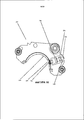
[0044] Фиг. 6 представляет принципиальную схему роторного двигателя, имеющего изолированный элемент, показанный на фиг. 3 с изогнутым профильным элемент, кривошипный центральный элемент, фиксатор, коленчатый вал и стенку внешней камеры.[0044] FIG. 6 is a circuit diagram of a rotary engine having an insulated member shown in FIG. 3 with a curved profile element, a crank central element, a latch, a crankshaft and the wall of the external chamber.
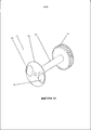
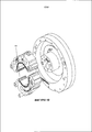
[0045] Фиг. 7 - перспективное изображение камеры двигателя с пространственным разделением деталей, представляющее составные части и выравнивающие штыри.[0045] FIG. 7 is a perspective view of an engine chamber with a spatial separation of parts, representing the constituent parts and alignment pins.
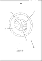
[0046] Фиг. 8 - вид в перспективе изолированного элемента на опорной пластине.[0046] FIG. 8 is a perspective view of an insulated element on a support plate.
[0047] Фиг. 9 - вид сбоку контура, изображающий размещение роликоподшипника.[0047] FIG. 9 is a side view of a contour depicting the placement of a roller bearing.
[0048] Фиг. 10 - вид сбоку камеры двигателя с контуром, находящимся в положении сжатия.[0048] FIG. 10 is a side view of an engine chamber with a contour in a compression position.
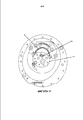
[0049] Фиг. 11 - вид сбоку камеры двигателя с контуром, находящимся в положении расширения.[0049] FIG. 11 is a side view of an engine chamber with a contour in an expansion position.
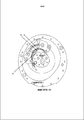
[0050] Фиг. 12 - вид сбоку камеры двигателя с контуром, находящимся в положении выпуска.[0050] FIG. 12 is a side view of an engine chamber with a contour in the exhaust position.
[0051] Фиг. 13 - вид сбоку камеры двигателя с контуром, находящимся в положении впуска.[0051] FIG. 13 is a side view of the engine chamber with a circuit in the intake position.
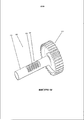
[0052] На фиг. 14 показан вид в перспективе конструкции цилиндрового клапана.[0052] FIG. 14 is a perspective view of a cylinder valve structure.
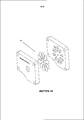
[0053] На фиг. 15 показан вид в перспективе конструкции вращательного клапана.[0053] FIG. 15 is a perspective view of a design of a rotary valve.
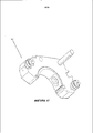
[0054] Фиг. 16 - вид сбоку контура с установленной в нем свечой зажигания.[0054] FIG. 16 is a side view of a circuit with a spark plug installed therein.
[0055] На фиг. 17 показан вид в перспективе корпуса, выполненного с возможностью установки со свечой зажигания.[0055] In FIG. 17 shows a perspective view of a housing configured to be installed with a spark plug.
[0056] На фиг. 18 - покомпонентное изображение конструкции лепесткового клапана.[0056] FIG. 18 is an exploded view of a flap valve structure.
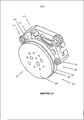
[0057] На фиг. 19 - покомпонентное изображение двухконтурного двигательного узла.[0057] FIG. 19 is an exploded view of a bypass motor assembly.
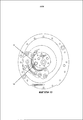
[0058] Фиг. 20 - передний вид в вертикальном разрезе варианта опорной пластины.[0058] FIG. 20 is a front elevational view of a variant of a support plate.
[0059] На фиг. 21 показан вид в перспективе варианта корпуса и передней пластины.[0059] FIG. 21 is a perspective view of an embodiment of the housing and the front plate.
ОПИСАНИЕ ВАРИАНТОВ РЕАЛИЗАЦИИ ИЗОБРЕТЕНИЯDESCRIPTION OF EMBODIMENTS OF THE INVENTION
[0060] Как указано в части "Предпосылки создания настоящего изобретения", при производстве IDAR двигателя имеют дело со сложными изогнутыми и плоскими поверхностями. Изолирующие поверхности выполнены плоскими и ориентированы в направлении длины герметизирующего элемента.[0060] As indicated in the "Background of the Present Invention", in the manufacture of an IDAR engine, complex curved and flat surfaces are dealt with. The insulating surfaces are flat and oriented in the direction of the length of the sealing element.
Двигатель также выполнен таким образом, что участки с плоскими поверхностями расположены рядом друг с другом с образованием полного двигателя. Это означает, что если какая-то поверхность не является плоской или расположена спереди или сзади, это может привести к ошибке во всем устройстве. В случае развития ошибки возрастает сложность герметизации соответствующих поверхностей относительно друг друга. Кроме того, чем шире участок, тем сложнее выполнить полную поверхность плоской по всей ее ширине.The engine is also designed so that areas with flat surfaces are located next to each other with the formation of a full engine. This means that if some surface is not flat or is located in front or behind, this can lead to an error in the entire device. In case of development of an error, the complexity of sealing the corresponding surfaces with respect to each other increases. In addition, the wider the area, the more difficult it is to make a full surface flat across its entire width.
[0061] Для уменьшения уровня точности относительной плоскостности и уменьшения общей ошибки по всем поверхностям лучше всего подвергнуть все участки плоскому шлифованию спереди и сзади. Плоское шлифование может уменьшить изменение плоскостности поверхностей до менее 1/10000 дюйма по поверхности, если используется шлифовальный станок, обеспечивающий соответствующую точность. Это обеспечивает точность по более широкой области. Таким образом, лучше всего выполнять реальную камеру двигателя в виде по меньшей мере двух частей вместо одной.[0061] In order to reduce the accuracy level of relative flatness and to reduce the total error on all surfaces, it is best to flatten all areas in front and rear. Flat grinding can reduce the change in flatness of surfaces to less than 1/10000 of an inch across the surface if a grinding machine is used to ensure adequate accuracy. This provides accuracy over a wider area. Thus, it is best to execute a real engine chamber in the form of at least two parts instead of one.
[0062] Обычно камера представляет собой приблизительно округлую деталь из метала, примерно толщина контура и дополнительная величина формируют заднюю часть камеры. Также обычно в камере делают углубления обрабатывающими головками, "управляемыми" компьютером, которые достигаю полости. Если камера выполнена в виде одиночной детали, она будет иметь краевой участок, который не позволит шлифовальному кругу шлифовать заднюю полость камеры для достижения точности плоскостности.[0062] Typically, the camera is an approximately rounded metal part, approximately the thickness of the contour and an additional amount form the back of the camera. Also, usually in the chamber, grooves are made with machining heads "controlled" by the computer, which reach the cavity. If the camera is made in the form of a single part, it will have an edge section that will not allow the grinding wheel to grind the rear chamber cavity to achieve flatness accuracy.
[0063] Если камера выполнена более чем из одной части, то краевой участок может быть одной частью, а задняя полость может быть другой частью. Тогда опорная пластина может быть отдельно обработана для достижения точности и прикреплена к краевому участку выравнивающими штырями или винтами для формирования целой камеры.[0063] If the camera is made of more than one part, then the edge portion may be one part, and the posterior cavity may be another part. The support plate can then be individually machined to achieve accuracy and attached to the edge portion with alignment pins or screws to form an entire chamber.
[0064] Другой аспект изолирующих плоских поверхностей состоит в том, что в любой трехмерной плоскости две изолирующие поверхности пересекутся под правильным углом. Это означает изолирование углового области, что требует не только, чтобы параллельные плоскости были плоскими относительно друг друга, но также чтобы перпендикулярные поверхности были под точными прямыми углами. В этом случае также помогает плоское шлифование каждого участка отдельно.[0064] Another aspect of insulating planar surfaces is that in any three-dimensional plane, two insulating surfaces intersect at a right angle. This means isolating the corner region, which requires not only that the parallel planes are flat relative to each other, but also that the perpendicular surfaces are at exact right angles. In this case, flat grinding of each section separately also helps.
[0065] Задачей IDAR двигателя является сохранение выравнивания плоскими поверхностями, выровненными с другими плоскими поверхностями, которые могут быть в движении. Это означает, что никакая часть не должна поворачиваться при своем движении по всем тактам. Подвижные контуры являются единственными частями, имеющими изолирующие поверхности, и они перемещаются в пределах камеры.[0065] The task of an IDAR engine is to maintain alignment with planar surfaces aligned with other planar surfaces that may be in motion. This means that no part should be rotated while moving along all measures. Movable circuits are the only parts that have insulating surfaces, and they move within the chamber.
[0066] Фиг. 7-13 изображают IDAR двигатель 20 согласно раскрытому варианту реализации. IDAR двигатель имеет камеру 22 сгорания и рабочий объем 24, т.е. объем, в котором происходит впуск, сжатие, сгорание и выпуск горючего вещества.[0066] FIG. 7-13 depict an
[0067] Подробнее, IDAR двигатель 20 включает переднюю пластину 26, изолированный элемент 28, контур 30, краевой участок 32 и опорную пластину 34. Эти компоненты IDAR двигателя имеют такие противоположные передние стороны 36-44 и задние стороны (не показаны), что в двигателе 20 задняя сторона передней пластины расположена у передней стороны 38 изолированного элемента и передней стороны 40 контура, а передняя сторона 44 опорной пластины расположена у задней стороны изолированного элемента и задней стороны краевого участка.[0067] In more detail, the
[0068] Передняя пластина 26, изолированный элемент 28, контур 30, краевой участок 32 и опорная пластина 34 имеют каждый внешнюю поверхность 56-64, контур 30 и краевой участок 32 имеют внутренние поверхности 66, 68, а опорная пластина 34 содержит дополнительную опорную пластину 70 с внешним краем 72. На основе этих компонентов IDAR двигателя можно сказать, что камера 22 сгорания IDAR двигателя определяется внутренней поверхностью 68 краевого участка и внешней поверхностью 58 изолированный элемент, а рабочий объем определяется внутренней поверхностью 66 контура и внешней поверхностью 58 изолированного элемента.[0068] The
[0069] Внешний край 72 дополнительной опорной пластины выполнен достаточно большим, чтобы покрывать впускное и выпускное выходные отверстия, выполненные в задней стороне опорной пластины, а также входные отверстия, выполненные в дополнительной пластине. Форма дополнительной опорной пластины может быть кругообразной. Дополнительная опорная пластина, наряду с остаточной частью опорной пластины и передней пластины 26, герметизирует рабочий объем 24, но не герметизирует камеру 22 сгорания, как описано подробно далее.[0069] The
[0070] Внешняя поверхность 58 изолированного элемента имеет форму, которая, как подробно описано далее, основана на формуле, представленной в части "Предпосылки создания настоящего изобретения". Все остальные внешние и внутренние края, кроме внешнего края 62 краевой части внешнего края 64 опорной пластины, представляют собой функцию от формы изолированного элемента.[0070] The
[0071] Краевая часть и внешние края 62, 64 опорной пластины не зависят от формы камеры сгорания. Кроме того, поскольку топливо удерживается в рабочем объеме, толщина краевой части по существу не зависит от формы рабочего объема. Другими словами, пока задняя сторона контура находится по существу вровень с задней стороной краевой части на опорной пластине 34, передняя сторона 38 контура может проходить за переднюю сторону 42 краевой части на расстояние, требуемое для формирования рабочего объема. Соответственно, краевая часть и опорная пластина могут быть выполнены из одной и той же заготовки и, как показано, иметь одинаковую форму внешнего края и толщину.[0071] The edge portion and the
[0072] Внешние края краевой части и опорной пластины 62, 62 каждый включает нижний контур 74, 76, пригодный для содействия в удерживании IDAR двигателя на месте при его изготовлении при установке в автомобиль. Нижние контуры 74, 76 можно в целом описать так, что они имеют радиус, смещенный к внешним радиусам краевой части и опорной пластины, с закругленными или уменьшенными противоположными внутренними краями, например 78, 80.[0072] The outer edges of the edge portion and the
[0073] Краевая часть 32 и опорная пластина 34 имеют согласующиеся установочные отверстия 82-88, проходящие в направлении толщины пластин, которые выполнены с возможностью принятия установочных штырей 90, 92. Установочные отверстия 82-88 примерно на (180) градусов смещены друг от друга и расположены на расстоянии от внешних краев краевой части и опорной пластины 62, 64.[0073] The
[0074] Когда установочные штыри 90, 92 размещены на своем месте, зажимные болты или подобные элементы пропускают через группы крепежных отверстий, например, 94, 96, проходящих в направлении толщины пластин и расположенных по периферии относительно внешнего диаметра краевого участка и опорной пластины 32, 34. Говоря о чертеже, имеется более дюжины таких крепежных отверстий в каждой пластине.[0074] When the mounting pins 90, 92 are in place, clamping bolts or the like are passed through groups of mounting holes, for example, 94, 96, extending in the direction of plate thickness and located peripherally with respect to the outer diameter of the edge portion and the
[0075] Группа установочных отверстий 98-108 выполнена в слое передней пластины 26, изолированного элемента 28 и опорной пластины 34. Вторая пара установочных штырей 110, 112 проходит через отверстия 98-108 для установки передней пластины 26, изолированного элемента 28 и опорной пластины 34 рядом друг с другом. При таком размещении контур 30 располагается у изолированного элемента 28, как будет понятно из данного раскрытия изобретения.[0075] A group of mounting holes 98-108 is formed in the layer of the
[0076] Каждый из компонентов, включающих переднюю пластину 26, изолированный элемент 38 и опорную пластину 34, имеет согласующиеся крепежные отверстия, например, 114-118, проходящие в направлении толщины. На чертеже каждый имеет по восемь таких крепежных отверстий. Посредством этих отверстий передняя пластина 26, изолированный элемент 38 и опорная пластина 34 прикреплены друг к другу после использования установочных штырей 110-112.[0076] Each of the components including the
[0077] Каждый из компонентов, включающих контур 30, краевую часть 32 и опорную пластину 34, имеет отверстия 120-130, выполненные с фаской в соответствующих передних сторонах, которые принимают участие в производственном процессе. Например, эти отверстия обеспечивают закрепление пластин и контуров на столах обработки с ЧПУ. Передняя пластина 26 и изолированный элемент 28 каждая имеет по меньшей мере одно отверстие 132, 134, выполненное с фаской в их соответствующих передних сторонах, с одинаковой целью.[0077] Each of the components including the
[0078] Выполненные с фаской отверстия на краевой части 32 и опорной пластине 34 расположены по периферии, примыкая к внешним краям 62, 64. Выполненные с фаской отверстия в контуре 30 расположены на расстоянии друг от друга, как показано на чертеже, для обеспечения приемлемого расстояния и в результате надлежащего содействия в обработке. Выполненные с фаской отверстия на передней пластине 26 и изолированном элементе 28 расположены так, чтобы обеспечить дополнительную функцию функционирования в виде клапанного канала, как описано далее.[0078] The chamfered holes on the
[0079] Опорная пластина 34 также включает отверстие 136 впуска горючего вещества и отверстие 138 выпуска горючего вещества. Отверстия 136, 138 определены округлыми отверстиями 140, 142 на задней стороне 44 опорной пластины. Особенность расположения этих отверстий станет понятной из описания фаз впуска и выпуска цикла сгорания, имеющегося далее. Округлое отверстие 142 для выпуска имеет больший диаметр, чем округлое отверстие 140 для впуска для обеспечения выпуска увеличенных в объеме горючих веществ. Округлые отверстия для впуска и выпуска имеют такую же площадь, что и в схожем образом расположенном двигателе внутреннего сгорания поршневого типа.[0079] The
[0080] Отверстия 140, 142 проходят к передней стороне 44 опорной пластины посредством соответствующих дугообразных изогнутостей 144, 146, цель которых максимизировать скорость потока впуска и выпуска от соответствующих отверстий 136, 138.[0080] The
[0081] Вследствие сложного характера дугообразных изогнутостей, рассмотренного далее, эти изогнутости выполняются фрезерованием в дополнительной опорной пластине 70, а не в опорной пластине 34. Дополнительная опорная пластина присоединена в передней стороне 44 опорной пластины. Как может быть ясно, дополнительная опорная пластина 70 может быть тонким элементом из какого-то материала вследствие минимальных конструкционных требований, предъявляемых ей.[0081] Due to the complex nature of the arcuate curvatures discussed below, these curvatures are performed by milling in the
[0082] Опорная пластина 34 также включает отверстие 148 свечи зажигания, расположенное в области, в которой происходит сжатие. Отверстие 150 сенсора также расположено в области, в которой происходит сжатие.[0082] The
[0083] Возвращаясь к изолированному элементу 38, показанному на фиг. 7 и 8, внешний контур можно описать как некруглый, вытянутый и выпуклый. Этот контур сформирован с использованием формулы и способа, описанных в части "Предпосылки создания настоящего изобретения". После генерации формы в такой программе, как SolidWorks, доступной от компании Dassault Systemes SolidWorks Corp. (300 Baker Avenue, Concord, MA, 01742) на может быть легко масштабирована для соответствия заданным параметрам.[0083] Returning to the
[0084] В качестве альтернативы, овал, например эллипс, со смещенным расположением коленчатого вала, обеспечит похожую структуру с похожими преимуществами. Также, эллипс может быть создан в программе SolidWorks и масштабирован при необходимости. Эллипс имеет большую ось и малую ось, и в раскрытых вариантах реализации большая ось по меньшей мере на 25% больше малой оси. Расстояние между фокальной точкой и локальным краем на главной оси (semilatus rectum) может быть оптимизировано, с учетом того, что большая величина этой переменной обеспечит большую величину расширение относительно сжатия. Также, это может быть оптимизировано с использованием программы SolidWorks, в зависимости от конструкционных ограничений.[0084] Alternatively, an oval, such as an ellipse, with an offset crankshaft, will provide a similar structure with similar advantages. Also, an ellipse can be created in SolidWorks and scaled if necessary. The ellipse has a major axis and a minor axis, and in the disclosed embodiments, the major axis is at least 25% larger than the minor axis. The distance between the focal point and the local edge on the main axis (semilatus rectum) can be optimized, taking into account the fact that a large value of this variable will provide a large amount of expansion relative to compression. Also, this can be optimized using the SolidWorks software, depending on design constraints.
[0085] Кроме того, каждый из компонентов, включающих переднюю пластину 26, изолированный элемент 28 и опорную пластину 34, имеют отверстия 156-160 для коленчатого вала. В отношении элемента 28, расположение отверстия 158 коленчатого вала может быть описано, как указано в части "Предпосылки создания настоящего изобретения", с использованием раскрытых там формул.[0085] In addition, each of the components including the
[0086] В качестве альтернативы, с использованием эллипса расположение отверстия коленчатого вала по существу находится в правом нижнем секторе графика, созданного большой и малой осями эллипса. На чертеже внешний диаметр отверстия с фаской по касательной соприкасается с большой и малой осями эллипса (см. фиг. 10). Однако отверстие с фаской может быть перемещено далее в этом секторе при необходимости. При таком перемещении отверстия с фаской далее в этом секторе подвижный контур перемещается более медленно при прохождении этапа сжатия, что меняет хронометраж такта сгорания. Опять же, это может быть оптимизировано при заданных конструкционных параметрах посредством моделирования в программе SolidWorks.[0086] Alternatively, using an ellipse, the location of the crankshaft hole is essentially in the lower right sector of the graph created by the major and minor axes of the ellipse. In the drawing, the outer diameter of the chamfered hole is tangentially in contact with the major and minor axes of the ellipse (see Fig. 10). However, the chamfered hole can be moved further in this sector if necessary. With such a movement of the chamfered hole further in this sector, the movable circuit moves more slowly during the compression stage, which changes the timing of the combustion cycle. Again, this can be optimized for given structural parameters through modeling in SolidWorks.
[0087] Отверстие коленчатого вала в передней пластине выполнено с фаской на его передней стороне, так что диск, прикрепленный к коленчатому валу и описанный далее, может быть установлен вровень с передней пластиной.[0087] The hole of the crankshaft in the front plate is chamfered on its front side, so that the disk attached to the crankshaft and described later can be installed flush with the front plate.
[0088] На фиг. 9 и 10 показан контур 30 на этапе сжатия такта сгорания. Как видно, внутренняя поверхность 66 контура представляет собой функцию внешней поверхности 58 изолированного элемента. Другими словами, внутренняя поверхность 66 контура по существу имеет ту же форму, что и изолированный элемент в зоне сжатия, но немного больше, чтобы перемещаться свободно вокруг изолированного элемента. Это пространство также отрегулировано для получения желаемого коэффициента сжатия для рабочего объема. Как показано, контур имеет противоположные по существу периферийные края 162, 164.[0088] FIG. 9 and 10 show the
[0089] Рабочий объем в этом участке такта сгорания эквивалентен размера поршня в положении в верхней мертвой точке. Расположение отверстия 148 свечи зажигания определяет положение вставляемых электродов в центре рабочего объема во время пика сжатия. Отверстие 150 сенсора открыто воздействию горючего вещества в этом положении контура в камере 22.[0089] The displacement in this portion of the combustion stroke is equivalent to the size of the piston at the top dead center position. The location of the
[0090] Контур включает пару боковых герметизирующих элементов 166, 168 на своей передней и задней сторонах (только передние герметизирующие элементы показаны). Боковые герметизирующие элементы на передней стороне контура осуществляют уплотнение задней поверхности передней пластины 46. Боковые герметизирующие элементы на задней стороне контура осуществляют уплотнение дополнительной опорной пластины 70 на опорной пластине 34.[0090] The contour includes a pair of
[0091] Боковые герметизирующие элементы ограничивают в двух парах апертур 170, 172 герметизирующих элементов верхней части (герметизирующие элементы не показаны), одна пара расположена на каждом противоположном периферийном конце контура 162, 164. Герметизирующий элемент верхней части проходит между передней пластиной и выступом, они контактируют с изолированным элементом, поверхностью передней пластины и задней пластины, и выполнены, например, из чугуна. Действие герметизирующих элементов заключается в герметизации горючего вещества в рабочем объеме.[0091] The lateral sealing elements are limited in two pairs of
[0092] В каждой паре апертур герметизирующих элементов верхней части апертура 174 внешнего герметизирующего элемента ограничивает радиально внешнюю часть апертуры 176 внутреннего герметизирующего элемента. Этот радиальный градиент способствует в предотвращении заклинивания контура при вращении вокруг изолированного элемента.[0092] In each pair of apertures of sealing elements of the upper part of the
[0093] Контур 30 включает пару роликовых подшипников 178, 180, расположенных на передней стороне контура 30. Подшипник 178, 180 расположены на противоположных периферийных краях контура 30 и радиально во внешней части от герметизирующих элементов верхней части боковых герметизирующих элементов на противоположных краях 182, 184 внешней поверхности 60 контура. Подшипники вращаются относительно внешнего края 56 передней пластины во время работы IDAR двигателя, так что внешний край 56 служит в качестве направляющего края. Соответственно, траектория такого движения определяет профиль внешнего края 56 передней пластины.[0093] The
[0094] Как показано на чертежах, противоположные края 182, 184 внешней поверхности 6 контура, и поэтому внешний край 56 передней пластины, находятся радиально в пределах внутренней поверхности 68 краевой части. Это обеспечивает то, что концы 182. 184 не нарушают движения контура 30 во время работы IDAR двигателя.[0094] As shown in the drawings, the
[0095] Внешняя поверхность 60 контура соединяется с внутренней поверхностью краевой части в одном месте. Это место является внешним пиком 186 во внешней поверхности 60 контура. Внешний пик 186 контура также является местом отверстия 188 кривошипного центрального элемента. Как было указано в части "Предпосылки создания настоящего изобретения" положение внешнего пика контура смещено по окружности в направлении периферийного края 164, например, на 25 процентов, если сравнивать с геометрическим центром контура. В качестве альтернативы, при использовании SolidWorks, положение может быть оптимизировано на основе критериев проектирования посредством перемещения внешнего пика далее в направлении или противоположно поверхности изолированного элемента или в направлении периферийного края 162 контура или периферийного края 164 контура.[0095] The
[0096] Сохраняя внешний пик контура на том же самом радиальном расстоянии от поверхности изолированного элемента и перемещая внешний пик контура в направлении любого из периферийных концов контура, можно изменить положение верхней мертвой точки, и таким образом фазируя движение контура относительно такта сгорания. В свою очередь, уменьшая это радиальное расстояние, но удерживая периферийное расстояние постоянным, можно получить сниженное преимущество в виде меньшего пространства для расположения всех компонентов контура. Проталкивая внешний пик контура радиально далее от поверхности изолированного элемента, краевая часть может стать слишком большой, при этом не обязательно получая преимущества в виде реализации крутящего момента.[0096] By maintaining the external peak of the contour at the same radial distance from the surface of the insulated element and moving the external peak of the contour in the direction of any of the peripheral ends of the contour, you can change the position of the top dead center, and thus phasing the movement of the contour relative to the combustion cycle. In turn, reducing this radial distance, but keeping the peripheral distance constant, you can get a reduced advantage in the form of less space for the location of all components of the circuit. By pushing the external peak of the contour radially further from the surface of the insulated element, the edge part may become too large, while not necessarily gaining in the form of torque.
[0097] Контур включает ролик 192 внешнего пика, обеспечивающий плавное качение внешнего пика 186 контура у краевой части. Соответственно, толщина краевой части по существу не зависит от рабочего объема и при этом обладает достаточной величиной для поддержки ролика 192. Кроме того, профиль внутренней поверхности 68 краевой части выполнен таким, чтобы удерживать контур в положении, при котором герметизирующие элементы 170, 172 верхней части непрерывно уплотняют внутреннюю поверхность контура 66.[0097] The contour includes an
[0098] Как видно, профили внешней поверхности 56 передней пластины, внешней поверхности 58 изолированного элемента, внутренней поверхности 66 контура, внешней поверхности 60 контура, профиля дополнительной опорной основы (вследствие расположения отверстий впуска и выпуска), а также внутренняя поверхность 68 краевой части все взаимно зависимы. Из этих компонентов, поверхность 58 является начальной точкой, поскольку она обеспечивает наибольший результат в эффективности IDAR технологии.[0098] As you can see, the profiles of the
[0099] Фиг. 11 иллюстрирует фазу расширения такта сгорания. Рабочий объем этого сегмента такта сгорания эквивалентен размерам поршня в положении нижней мертвой точки. Сравнение этого чертежа с фиг. 10 может помочь с пониманием дугообразного отверстия 146 выпуска. Во время такта расширения отверстие выпуска "закрыто". Для достижения этого отверстие выпуска имеет ведущий край 194, т.е. тот край, который первым достигается контуром 30. Этот край 194 расположен так, что внутренний край контура 66 не контактирует с отверстием выпуска, пока фаза расширения не выполнена. Как показано на фиг. 11, ведущий край 194 отверстия выпуска не видим в рабочем объеме.[0099] FIG. 11 illustrates the expansion phase of a combustion cycle. The working volume of this segment of the combustion stroke is equivalent to the size of the piston at the bottom dead center position. A comparison of this drawing with FIG. 10 may help with understanding the
[00100] На фиг. 12 представлена фаза выпуска такта сгорания. Сравнивая с фиг. 10, отверстие выпуска имеет верхний край 196, задний край 198 и радиальный внутренний край 200. Эти края по существу копируют проекцию внутренней поверхности 66 контура у дополнительной опорной основы 70 в месте контура 30 у пика фазы выпуска. Угловое разделение 202 в профиле 146 выпуска способствует контролю за потоком отработанных горючих веществ. Разделение 202 выровнена с направлениями потоков в свеем расположении.[00100] FIG. 12 shows the phase of exhaustion of a combustion cycle. Comparing with FIG. 10, the outlet opening has an
[00101] На фиг. 13 показана фаза впуска такта сгорания. Форма дугообразного отверстия 142 впуска может быть понята из сравнения фиг. 13 с фиг. 10 и 12 и понимания, как было получено дугообразное отверстие выпуска.[00101] In FIG. 13 shows the intake phase of the combustion cycle. The shape of the
[00102] Дугообразное отверстие впуска имеет ведущий край 204 (фиг. 12), который не выдается на контур 30, когда контур находится в положении максимального выпуска. Дугообразное отверстие впуска имеет нижний край 206, основанный на проекции контура на опорную пластину, когда контур проходит по фазе впуска, как проиллюстрировано на фиг. 1. Первый участок 208 верхнего края впуска проходит к изолированному элементу, а второй, больший участок 210, не проходит. Участок 210 повторяет контур внутренней поверхности 66 в начале фазы сжатия (не показано). Группа отверстий 212 и угловое разделение 214 также имеются для обеспечения надлежащего потока горючего вещества. Разделение 214 проходит в направлении линий потока в своем расположении.[00102] The arcuate inlet opening has a leading edge 204 (FIG. 12), which is not projected onto the
[00103] Роликовые подшипники 178, 180, рассмотренные выше, удерживают контур 30 от поворотов и переплетения от герметизирующих элементов 166, 168 и 170, 172 во время описанного выше такта сгорания. Подшипники 178, 180 забирают крутящие моменты с герметизирующих элементов 166-172 и контура 30.[00103] The
[00104] Улучшение объемного КПД приема в IDAR технологии можно получить в следующих альтернативных вариантах реализации. В качестве альтернативы отверстие 136 впуска, небольшие отверстия (не показаны), аналогичные по размеру отверстиям 212, как показано на фиг. 10, могут быть выполнены обработкой под прямым углом через внешнюю поверхность 58 изолированного элемента. Эти отверстия выполнены с получением отверстия 132 с фаской на изолированном элементе, в месте, где округлое отверстие 140 впуска расположено в ранее раскрытом варианте реализации. Соответствующее отверстие 218 с фаской обеспечено в передней пластине 26, а также через отверстие 220 в опорной пластине 34. Эти отверстия имеют диаметр около (1/2) дюйма.[00104] An improvement in volumetric reception efficiency in IDAR technology can be obtained in the following alternative embodiments. Alternatively, the
[00105] Цилиндровый клапан 222, как показано на фиг. 14, вставляется в отверстие 218 передней пластины и в канал, созданный отверстием 132, для контроля открытием и закрытием меньших отверстий впуска. В частности, цилиндровый клапан включает полый цилиндр 224 с двумя группами 226, 228 слотов (семь слотов показано в каждой группе) на периферийных противоположных сторонах клапана 222. Слоты перпендикулярны продольной оси цилиндрового клапана и проходят за цилиндровый клапан примерно на четверть от общей окружности клапана.[00105]
[00106] Клапан включает зубчатый верхний диск 230, который установлен и вращается в пределах вдавливания 218 с фасками. Передачи 230 зацепляются с идентичной передачей на коленчатом вале (не показано), расположенной в первом отверстии 134 с фасками передней пластины. С таким зацеплением, клапан 222 может открываться и закрываться в два раза за каждый оборот IDAR двигателя.[00106] The valve includes a toothed
[00107] Объемный коэффициент полезного действия (объемный КПД) двигателя отражает эффективность всасывания в цилиндр и выпуска из цилиндра рабочей среды. Данный коэффициент выражает отношение количества рабочей среды, фактически всасываемой в цилиндр, к объему самого цилиндра. Поэтому за счет создания давления на входе в двигатель выше давления окружающей среды. С помощью указанной выше технологии наблюдались значения объемного КПД больше 100%.[00107] The volumetric efficiency (volumetric efficiency) of the engine reflects the efficiency of suction into the cylinder and exhaust from the cylinder of the working medium. This coefficient expresses the ratio of the amount of working medium actually absorbed into the cylinder to the volume of the cylinder itself. Therefore, by creating a pressure at the inlet of the engine above ambient pressure. Using the above technology, values of volumetric efficiency of more than 100% were observed.
[00108] Альтернативные конфигурации впуска включают в себя первоначально раскрытые отверстие 136 впуска и вращательный клапан 232, показанные на фиг. 15. Этот вариант реализации не включает в себя меньшие отверстия во внешней поверхности 60 контура, но включает дополнительное отверстие 218 с фасками в передней пластине и опорную пластину через отверстие 220.[00108] Alternative inlet configurations include the originally opened
[00109] Вращательный клапан 232 также включает верхний зубчатый диск 230, цилиндр 234, которые могут быть или не быть полыми, и нижний диск 236. Нижний диск 236 установлен у нижней поверхности опорной пластины и имеет диаметр, который достаточно велик, чтобы проходить за округлое отверстие 140 впуска.[00109] The
[00110] Нижний диск 236 имеет два дугообразных отверстия 238, 240, на периферийных противоположных местах на диске 236. Каждое отверстие занимает примерно от тридцати до сорока процентов площади диска 236. При таком клапане 232, впуск 136 открывается и закрывается два раза за каждый оборот двигателя дисковыми отверстиями 238, 240.[00110] The
[00111] Еще один альтернативный вариант реализации показан на фиг. 16 и 17. В этом варианте отверстие 148 ввода свечи зажигания в опорной пластине 34 не является нужным. Напротив, в этом варианте альтернативной подвижной контур 242 включает в себя одно или более отверстий 244 с фасками, каждый из которых выполнено с возможностью размещения свечи зажигания 246. Отверстие 248 в отверстии 244 на внешней поверхности 250 контура обеспечивает доступ к свече зажигания, а отверстие 252 на внутренней поверхности контура 254 позволяет помещать электроды 256 в рабочий объем. Антенные провода (не показаны) крепятся к соединению свечи зажигания.[00111] Another alternative embodiment is shown in FIG. 16 and 17. In this embodiment, the spark
[00112] По сравнению с размещения свечи зажигания в фиксированном положении в опорной пластине, этот альтернативный вариант реализации обеспечивает высоко предсказуемое сжигание, даже при разных скоростях движения контура. Это происходит по причине того, что установленные в контуре свечи зажигания находятся всегда в точном положении, в котором желательно иметь начало процесса горения.[00112] Compared to placing the spark plug in a fixed position in the support plate, this alternative embodiment provides highly predictable combustion, even at different speeds of the circuit. This is due to the fact that the spark plugs installed in the circuit are always in the exact position in which it is desirable to have the start of the combustion process.
[00113] Кроме того, создается искровой промежуток путем размещения металлической пластины (не показана), подключенной к высоковольтной катушке (не показана), рядом с областью горения вдоль передней пластины 26. При движении контура 242 около высоковольтной пластины, искра переходит к движущейся свече зажигания 248 и через свечу зажигания на зазор в свече зажигания для начала процесс горения.[00113] In addition, a spark gap is created by placing a metal plate (not shown) connected to a high voltage coil (not shown) next to the burning area along the
[00114] В еще одном альтернативном варианте реализации, потери при перекачке, связанные с тактом выпуска, могут быть уменьшены путем добавления контрольного лепесткового клапана 258, показанного в покомпонентном изображении на фиг. 18, на задней стороне опорной пластины, у отверстия 138 выпуска. Контуры проходят через область выпуска в течение такта выпуска, а затем оставляют отверстие выпуска открытым для атмосферного давления. Это приводит к увеличению трения в насосе, потому что газы не содержатся в одном направлении движения.[00114] In yet another alternative embodiment, pumping losses associated with the exhaust stroke can be reduced by adding the
[00115] В частности, лепестковый клапан герметизирует отверстие выпуска то время, когда нет контура 30, и предотвращает скопление выхлопа в камере двигателя. В другом варианте изобретения для этой цели используется вращательный клапан (не показан).[00115] In particular, the flap valve seals the outlet opening while there is no
[00116] В другом альтернативном варианте реализации контур модифицирован для хранения определенного количества выхлопа и соединяет его с новым топливом во время процесса впуска. Было бы желательно, при переходе от такта выпуска к такту впуска, в целях контроля за видом и количеством побочных продуктов сгорания.[00116] In another alternative embodiment, the circuit is modified to store a certain amount of exhaust and connects it to new fuel during the intake process. It would be desirable, in the transition from the exhaust cycle to the intake cycle, in order to control the type and amount of combustion by-products.
[00117] Тип контура, который может быть модифицирован, чтобы обеспечить внутреннюю рециркуляцию газа, похож на контур 242 на фиг. 17. Предусмотрена внутренняя поверхность отверстия 252, которая является полусферическим, что вместо того, чтобы ограничивать у отверстия 248 во внешней поверхности 250 контура, ограничивает внутри, в пределах контура, и захватывает отработанное горючее вещество. Таким образом, предварительно заданное количество выхлопных газов рекомбинируют с новым горючим веществом и используют для контроля температуры сгорания таким образом, чтобы снизить опасные загрязнители.[00117] The type of circuit that can be modified to provide internal gas recirculation is similar to
[00118] Кроме того, рециркуляция достигается перемещением или уменьшать размер отверстия выпуска, так что это не провод выпуска всего сжигаемого горючего (например, выходная площадь не может вместить поток выпускаемой массы), тем самым производя транспортировку остатка к новому горючему веществу во время впуска. Поршневой двигатель не способен выполнять это без использования дополнительных клапанов и сложного хронометража с использованием распределительного вала, как это известно для этой отрасли.[00118] In addition, recirculation is achieved by moving or reducing the size of the outlet opening, so that it is not the exhaust line of the entire combustible fuel (for example, the exit area cannot accommodate the flow of exhaust mass), thereby transporting the residue to the new combustible substance during the inlet. A piston engine is not able to do this without the use of additional valves and complex timing using a camshaft, as is known for this industry.
[00119] Фиг. 19 представляет покомпонентное изображение двухконтурного двигательного блока, включая исходный контур 30 и идентичный ему второй контур 260. Все аспекты выше первоначально раскрытого варианта реализации справедливы и для этого альтернативным варианта реализации. Результирующая структура является эквивалентом двух клапанного двигателя, хотя используется только одна камера.[00119] FIG. 19 is an exploded view of a bypass motor block, including an
[00120] Кроме того, с опорной пластиной 262, показанной на фиг. 20, описанный IDAR двигатель может быть использован за пределами технического класса двигателей внутреннего сгорания. IDAR технология имеет гораздо более предпочтительную механическую передачу в крутящий момент, чем в поршневой технологии с подобным смещением. Осуществляется вывод большей полезной работы на единицу смещения по сравнению с поршневыми технологии. В связи с этим, используя только IDAR такт расширения (горение, без искры индуцируемая вспышка) и IDAR такт выпуска, поддерживающие такты впуска и сжатия происходят во внешнем, но связанном устройстве, что повышает общую эффективность. Кроме того, при таком применении, по причине движения контура по-прежнему относительно всего изолированного элемента, такты впуска и сжатия в технологии IDAR могут быть использованы как вторичные относящиеся к IDAR технологии такты расширения и сжатия в одной камере.[00120] Furthermore, with the
[00121] Технически, эти применения используют только IDAR такты расширения и выпуска для обеспечения двигателей внешнего сгорания или силовых станций на сжатом воздухе вместо двигателей внутреннего сгорания. Воздух под высоким давлением или другое горючее вещество поступает из внешних, но соединенных устройств для осуществления движения контуров.[00121] Technically, these applications use only IDAR expansion and exhaust cycles to provide external combustion engines or compressed air power plants instead of internal combustion engines. High-pressure air or other combustible material comes from external but connected devices to carry out the movement of the circuits.
[00122] Для достижения такой альтернативной конфигурации опорная пластина 262 включает два отверстия 264, 266 впуска, которые могут быть одинаковыми по размеру с отверстиями для свеч зажигания, которые обеспечивают порты для трубок поставки воздуха под высоким давлением, который обеспечивает такт расширения. Также показаны два отверстия 266, 268 выпуска, которые имеют место в конце такта расширения. Отверстия выпуска выполнены, как указано выше. Противоположные отверстия расположены по существу на противоположных периферийных краях изолированного элемента, позволяя выполнять два полных приложений расширения и выпуска для каждого полного оборота контура внутри камеры.[00122] To achieve such an alternative configuration, the
[00123] Другими словами, поскольку нет впуска и сжатия, происходящих в двигателе (высокое сжатие воздуха осуществляется вне двигателя и другими средствами) эти два татка используются для удвоения в качестве второй такт расширения и выпуска. Для каждых 360 градусов вращения контур будет выполнить два такта расширения и два такта выпуска.[00123] In other words, since there is no intake and compression occurring in the engine (high air compression is performed outside the engine by other means), these two tattoos are used to double as a second expansion and exhaust stroke. For every 360 degrees of rotation, the circuit will perform two expansion cycles and two release cycles.
[00124] Фиг. 21 представляет собой альтернативный контур 270 и альтернативную переднюю пластину 272 по причинам, рассмотренным далее. В первом раскрытом контуре 30 подшипники 178, 180, на противоположных периферийных концах 162, 164 контура 30, выступают наружу от передней стороны контура 40 на том же расстоянии, и они имеют тот же внешний диаметр. Подшипники 178, 180 выступают за внешний край 56 передней пластины, который имеет равномерный радиальный внешний профиль 56.[00124] FIG. 21 is an
[00125] Противоположные периферийные края 162, 164 контура не двигаются по точно такой же траектории относительно внешней поверхности 58 изолированного элемента из-за асимметричной формы изолированного элемента 28. Их небольшое смещение по отношению к внешней поверхности изолированного элемента, при вращении контура вращается вокруг изолированного элемента, требует того, чтобы герметизирующие элементы верхней части двигались внутрь или наружу для регулировки незначительных различий.[00125] Opposite peripheral
[00126] Чтобы свести к минимуму нежелательное перемещения герметизирующих элементов верхней части на периферийных противоположных краях контура 274, 276, имеются подшипники 278, 280, которые выполнены с взаимно характерными признаками. А именно, подшипник 278 в ведущем периферийном крае 274 контура 270 выступает дальше от передней стороны 282 контура 270 и имеет больший наружный диаметр, чем подшипник 280 на заднем периферийном крае 276 контура 270.[00126] In order to minimize unwanted movement of the sealing elements of the upper part on the peripheral opposite edges of the
[00127] Чтобы получить эти подшипники 278, 280, внешний край 282 передней пластины 282 имеет два различных внешних профиля 284, 286, а именно, внешний профиль 284 и внутренний профиль 286. Внешний профиль 284 ближе к задней стороне передней пластины, а внутренний профиль 286 ближе к передней стороне 288 передней пластины.[00127] In order to obtain these
[00128] Внешний профиль 284 передней пластины радиально больше, чем внутренний профиль 286 передней пластины, а внешний профиль 284 выполнен для отслеживания траектории подшипника 280 заднего края. В свою очередь, внутренний профиль 286 выполнен для отслеживания траектории подшипника 278 ведущего края.[00128] The outer profile of the
[00129] Внешние диаметры ведущего 278 и заднего 280 краевых подшипников выполнены с возможностью установки у соответствующих профилей 286, 284. Стержень 290 ведущего подшипника 178 достаточно длинен и достаточно узок для размещения подшипника 278 по отношению к внутреннему профилю 286 без контакта с внешним профилем 284 передней пластины 272.[00129] The outer diameters of the
[00130] Следует отметить, что не важно, какой подшипник 278, 280, имеет более длинный стержень. В этом варианте реализации только важно, что передняя пластина имеет профили внешнего края, которые могут принимать соответствующие подшипники, и, что профили отслеживают траекторию, по которой перемещаются соответствующие подшипники 278, 280. Это позволит свести к минимуму или предотвратить нежелаемые перемещения контура 270 во время такта сгорания.[00130] It should be noted that it does not matter which bearing 278, 280 has a longer shaft. In this embodiment, it is only important that the front plate has external edge profiles that can receive the corresponding bearings, and that the profiles track the path that the corresponding
[00131] В целом, выше описанные варианты реализации обеспечивают возможность размещения одного или более роликового подшипника вдоль стороны подвижного контура таким образом, чтобы подшипники могли постоянно контактировать с внешней поверхностью передней пластины для осуществления поворота контур в камерной области при вращении контура вокруг неподвижного изолированного элемента.[00131] In general, the above-described embodiments provide the ability to position one or more roller bearings along the side of the movable contour so that the bearings can constantly contact the outer surface of the front plate to rotate the contour in the chamber region when the contour rotates around a stationary insulated element.
[00132] Камера сгорания выполнена в виде несколько частей, которые последовательно расположены в виде слоев так, чтобы формировать целый IDAR двигатель, и каждый слой выровнен в соответствии посредством выравнивающих штырей или коннекторов.[00132] The combustion chamber is made in the form of several parts, which are sequentially arranged in the form of layers so as to form an entire IDAR engine, and each layer is aligned in accordance with the alignment pins or connectors.
[00133] В одном из раскрытых вариантов реализации отверстие впуска подается через ряд небольших отверстий по периметру изолированного элемента, которые связаны с большим отверстием, проходящим через корпус изолированного элемента и из задней части камеры. В этом варианте реализации размещение цилиндрового клапана в задней части камеры и корпусе изолированного элемента, обеспечивает соединение и управление потоком впуска через отверстия впуска, сконфигурированные согласно изолированному элементу.[00133] In one of the disclosed embodiments, the inlet opening is fed through a series of small holes around the perimeter of the insulated element, which are connected with a large hole passing through the housing of the insulated element and from the back of the camera. In this embodiment, the placement of the cylinder valve in the rear of the chamber and the housing of the insulated element allows connection and control of the intake flow through the inlet openings configured according to the insulated element.
[00134] В другом раскрытом варианте реализации размещение вращательного клапана с прикрепленной стержневой частью, который проходит через заднюю часть камеры и корпус изолированного элемента, обеспечивает соединение и управление потоком впуска через впускные отверстия, сконфигурированные согласно изолированному элементу.[00134] In another disclosed embodiment, the placement of a rotary valve with an attached stem portion that extends through the back of the chamber and the housing of the insulated member allows connection and control of the inlet flow through inlets configured according to the insulated member.
[00135] В другом раскрытом варианте реализации, конфигурация двигателя с одной или более свечами зажигания, установленными в подвижных контурах с соединительным узлом к свече зажигания, присоединенной к антенне, которая собирает спланированную по времени энергию искры при своем перемещении по соседней области относительно к стационарному высоковольтному проводнику.[00135] In another disclosed embodiment, the configuration of the engine with one or more spark plugs mounted in movable circuits with a connection to a spark plug connected to an antenna that collects time-planned spark energy as it moves across an adjacent region relative to the stationary high voltage to the conductor.
[00136] В раскрытых вариантах реализации используются герметизирующие элементы верхней части, которые контактируют с поверхностью передней панелью и опорной панели.[00136] In the disclosed embodiments, sealing elements of the upper portion that contact the surface of the front panel and the back panel are used.
[00137] В одном из вариантов реализации на задней стороне камеры двигателя установлен лепестковый клапан над отверстием выпуска для осуществления открытия и закрытия этого отверстия.[00137] In one embodiment, a flap valve is installed on the rear side of the engine chamber above the exhaust opening to open and close this opening.
[00138] В другом раскрыты варианте поворотный клапан устанавливается на задней стороне камеры двигателя в выхлопной порт для осуществления открытия и закрытия выхлопного отверстия.[00138] In another embodiment, a rotary valve is mounted on the rear side of the engine chamber in the exhaust port to open and close the exhaust port.
[00139] В другом раскрытом варианте реализации удаляется часть поверхности вогнутого контура, которая обращена к поверхности изолированного элемента, для осуществления процесса внутренней рециркуляции газов непосредственно между тактами впуска и выпуска.[00139] In another disclosed embodiment, a portion of the surface of the concave contour that faces the surface of the insulated member is removed to implement an internal gas recirculation process directly between the intake and exhaust strokes.
[00140] Таким образом, была показана технологи я усовершенствования асимметричного роторного двигателя обратного смещения (IDAR) и внутреннего сгорания. Также описаны конструктивные улучшения камеры двигателя, которые упрощают процессы сборки и улучшить допуски в двигателе. Кроме того, описаны улучшение конфигурации контура, снимающие нагрузку на боковые герметизирующие элементы и герметизирующие элементы верхней части и улучшающие механизм сжатия в двигателе, функциональную воспроизводимость и срок службы двигателя. Также рассмотрены усовершенствования конструкции выводящих отверстий, как впускных и выпускных, и совместимая конструкция клапана для повышения производительности каждого такта.[00140] Thus, technology has been shown to improve an asymmetric reverse displacement rotary motor (IDAR) and internal combustion. Also described are structural improvements to the engine chamber that simplify assembly processes and improve engine tolerances. In addition, improvement of the configuration of the circuit is described, which removes the load on the side sealing elements and sealing elements of the upper part and improves the compression mechanism in the engine, functional reproducibility and engine life. Improvements in the design of the outlet openings, both inlet and outlet, and a compatible valve design to increase the performance of each cycle are also considered.
[00141] В другой рассмотренной конфигурации IDAR технологии было раскрыто расширение использования с привлечением других технологий, таких как IDAR функции в качестве силовой установки, в то время как существующие технологии обеспечивают источники воздуха с высоким давлением или смеси горючего вещества и воздуха для IDAR силовых установок. В этом случае устройство согласно IDAR технологии действует как силовая установка внешнего сгорания, например, работающая на сжатом воздухе, вместо двигателя внутреннего сгорания.[00141] In another configuration of IDAR technologies discussed, expansion of use has been disclosed involving other technologies such as IDAR functions as a power plant, while existing technologies provide high pressure air sources or a mixture of combustible matter and air for IDAR power plants. In this case, the device according to IDAR technology acts as a power plant for external combustion, for example, operating on compressed air, instead of an internal combustion engine.
[00142] Хотя выше было раскрыто несколько вариантов реализации настоящего изобретения, данное изобретение не должны быть ограничено ими. Фактически, следует понимать, что специалисты в данной области техники будет иметь возможность разработать многочисленные варианты, которые, хотя специально не показаны или не описаны, можно воплотить по принципам настоящего изобретения и которые попадет под его объем. Модификации раскрытых выше вариантов очевидны для специалистов в данной области техники, но это не должно привести к вариантам модифицирования изобретения, находящимся за пределами объема изобретения, определяемого прилагаемой формулой изобретения.[00142] Although several embodiments of the present invention have been disclosed above, the invention should not be limited to them. In fact, it should be understood that those skilled in the art will be able to develop numerous options that, although not specifically shown or described, can be embodied in accordance with the principles of the present invention and which fall within its scope. Modifications of the above options are obvious to those skilled in the art, but this should not lead to modifications of the invention that are outside the scope of the invention defined by the appended claims.
Claims (25)
неподвижный изолированный элемент, имеющий внешнюю поверхность и удлиненную выпуклую форму и включающий канал коленчатого вала, расположенный на расстоянии от центра указанного изолированного элемента,
переднюю пластину, присоединенную к передней поверхности указанного изолированного элемента и снабженную направляющим краем,
подвижный профильный элемент вогнутой формы, смещенный в направлении внешней поверхности изолированного элемента и выполненный с возможностью вращения вокруг изолированного элемента с образованием рабочего объема камеры между внутренней поверхностью профильного элемента и внешней поверхностью изолированного элемента,
и по меньшей мере один взаимодействующий с передней пластиной подшипник, проходящий от передней поверхности подвижного профильного элемента и над направляющим краем передней пластины, при этом взаимодействующий с передней пластиной подшипник выполнен с возможностью взаимодействия с указанным направляющим краем.1. Asymmetric rotary engine containing a camera, in turn, containing
a stationary insulated element having an outer surface and an elongated convex shape and including a crankshaft channel located at a distance from the center of the specified insulated element,
a front plate attached to the front surface of the specified insulated element and provided with a guide edge,
a concave movable profile element, offset in the direction of the outer surface of the insulated element and configured to rotate around the insulated element with the formation of the working volume of the chamber between the inner surface of the profile element and the outer surface of the insulated element,
and at least one bearing interacting with the front plate extending from the front surface of the movable profile element and above the guide edge of the front plate, while the bearing interacting with the front plate is configured to interact with said guide edge.
обод с внутренней поверхностью, причем по меньшей мере часть изолированного элемента и профильного элемента расположены в пределах внутренней поверхности обода,
подшипник для взаимодействия с внутренней поверхностью обода, проходящий от внешней поверхности подвижного профильного элемента,
причем внутренняя поверхность обода имеет такую форму, чтобы смещать профильный элемент в направлении изолированного элемента, посредством чего взаимодействующий с передней пластиной подшипник взаимодействует с направляющим краем.4. The engine according to claim 2, in which the camera further comprises
a rim with an inner surface, wherein at least a portion of the insulated element and the profile element are located within the inner surface of the rim,
a bearing for interacting with the inner surface of the rim passing from the outer surface of the movable profile element,
moreover, the inner surface of the rim is shaped so as to bias the profile element in the direction of the insulated element, whereby the bearing interacting with the front plate interacts with the guide edge.
боковые герметизирующие элементы, взаимодействующие с поверхностями передней пластины и опорной пластины, и
герметизирующие элементы верхней части, расположенные на периферийной поверхности профильного элемента и взаимодействующие с поверхностями изолированного элемента и передней пластины.11. The engine according to claim 6, in which the movable profile element further comprises
lateral sealing elements interacting with the surfaces of the front plate and the support plate, and
sealing elements of the upper part located on the peripheral surface of the profile element and interacting with the surfaces of the insulated element and the front plate.
клапанный канал, выполненный в изолированном элементе, и
цилиндрический щелевой клапан, установленный с возможностью вращения в клапанном канале таким образом, что горючее вещество выборочно доставляется в рабочий объем.15. The engine according to claim 4, including
a valve channel formed in an insulated member, and
a cylindrical slotted valve mounted rotatably in the valve channel so that the combustible material is selectively delivered to the working volume.
Applications Claiming Priority (3)
| Application Number | Priority Date | Filing Date | Title |
|---|---|---|---|
| US21119209P | 2009-03-25 | 2009-03-25 | |
| US61/211,192 | 2009-03-25 | ||
| PCT/US2010/028754 WO2010111557A2 (en) | 2009-03-25 | 2010-03-25 | Inverse displacement asymmetric rotary (idar) engine |
Publications (2)
| Publication Number | Publication Date |
|---|---|
| RU2011140081A RU2011140081A (en) | 2013-04-27 |
| RU2578072C2 true RU2578072C2 (en) | 2016-03-20 |
Family
ID=42781898
Family Applications (1)
| Application Number | Title | Priority Date | Filing Date |
|---|---|---|---|
| RU2011140081/06A RU2578072C2 (en) | 2009-03-25 | 2010-03-25 | Asymmetric rotary engine with reverse bias |
Country Status (13)
| Country | Link |
|---|---|
| US (2) | US8607762B2 (en) |
| EP (1) | EP2414635B1 (en) |
| JP (1) | JP5706394B2 (en) |
| KR (1) | KR20120011846A (en) |
| CN (1) | CN102575522B (en) |
| AU (1) | AU2010229818B2 (en) |
| BR (1) | BRPI1009834A2 (en) |
| CA (1) | CA2756230C (en) |
| IL (1) | IL215238A (en) |
| MX (1) | MX2011009891A (en) |
| RU (1) | RU2578072C2 (en) |
| WO (1) | WO2010111557A2 (en) |
| ZA (1) | ZA201106710B (en) |
Families Citing this family (14)
| Publication number | Priority date | Publication date | Assignee | Title |
|---|---|---|---|---|
| RU2578072C2 (en) | 2009-03-25 | 2016-03-20 | Люмениум Ллс | Asymmetric rotary engine with reverse bias |
| US20130224053A1 (en) * | 2011-10-03 | 2013-08-29 | Jan Hendrik Ate Wiekamp | Coaxial progressive cavity pump |
| CA2867388A1 (en) * | 2012-03-14 | 2013-09-19 | Lumenium Llc | Idar-ace inverse displacement asymmetric rotating alternative core engine |
| US10184392B2 (en) | 2012-03-14 | 2019-01-22 | Lumenium Llc | Single chamber multiple independent contour rotary machine |
| US9309765B2 (en) | 2012-03-14 | 2016-04-12 | Lumenium Llc | Rotary machine |
| CN106030037B (en) * | 2013-09-18 | 2018-09-14 | 卢门纽姆公司 | Rotary |
| US11920476B2 (en) | 2015-04-13 | 2024-03-05 | Lumenium Llc | Rotary machine |
| JP2018516340A (en) | 2015-04-13 | 2018-06-21 | ルメニウム エルエルシーLumenium Llc | Single-chamber multi-independent contour rotating machine |
| CN108350882B (en) | 2015-11-18 | 2019-11-15 | 雀巢产品有限公司 | Rotary Compressor device |
| TWI743126B (en) | 2016-07-08 | 2021-10-21 | 瑞士商雀巢製品股份有限公司 | Rotary compressor arrangement |
| CN113811667A (en) | 2018-11-27 | 2021-12-17 | 卢门纽姆公司 | Rotary engine with circulating arc roller power transmission |
| CN110359962B (en) * | 2019-07-17 | 2021-01-05 | 顾新钿 | Pneumatic motor |
| WO2021232025A1 (en) | 2020-05-15 | 2021-11-18 | Lumenium Llc | Rotary machine with hub driven transmission articulating a four bar linkage |
| CN113378319B (en) * | 2021-06-24 | 2022-04-12 | 宁波蓝海量子精工轴承制造有限公司 | Design method for end face grinding allowance of double-end-face asymmetric bearing ring |
Citations (3)
| Publication number | Priority date | Publication date | Assignee | Title |
|---|---|---|---|---|
| US3884600A (en) * | 1973-11-08 | 1975-05-20 | Gray & Bensley Research Corp | Guidance means for a rotary engine or pump |
| US6722321B2 (en) * | 2001-05-26 | 2004-04-20 | Dong-Hyun Kim | Rotary engine |
| RU2004138575A (en) * | 2002-07-16 | 2005-07-20 | Люмениум Ллс (Us) | REVERSED ASYMMETRIC ROTARY MOTOR WITH CONTINUOUSLY OPERATING TORQUE |
Family Cites Families (51)
| Publication number | Priority date | Publication date | Assignee | Title |
|---|---|---|---|---|
| US419770A (en) * | 1890-01-21 | Rotary engine | ||
| US613345A (en) * | 1898-11-01 | Reversible rotary engine | ||
| US709773A (en) * | 1902-03-08 | 1902-09-23 | Oliver C Jones | Rotary engine. |
| US1595496A (en) * | 1924-06-04 | 1926-08-10 | Beggs Thomas Robert | Fluid motor |
| US1972302A (en) * | 1932-11-08 | 1934-09-04 | Multicycol Pump & Engine Corp | Rotary pump, compressor, or the like |
| US1983033A (en) * | 1932-11-30 | 1934-12-04 | Multicycol Pump & Engine Corp | Rotary pump, compressor, or the like |
| US1986202A (en) * | 1933-01-21 | 1935-01-01 | Multicycol Pump & Engine Corp | Rotary pump, compressor, and the like |
| US1983034A (en) * | 1933-01-31 | 1934-12-04 | Multicycol Pump & Engine Corp | Rotary pump, compressor, engine, and the like |
| US2277225A (en) * | 1941-07-21 | 1942-03-24 | Edward H Green | Internal combustion engine |
| US2919062A (en) * | 1954-10-05 | 1959-12-29 | British Internal Combust Eng | Rotary compressing, displacing or expanding machine |
| US2897798A (en) * | 1956-07-02 | 1959-08-04 | Schrougham Benton | Rotary internal combustion engine |
| US3186385A (en) * | 1960-09-20 | 1965-06-01 | Hamilton Walker Rotary Engines | Rotary internal combustion engines |
| GB930280A (en) * | 1960-11-02 | 1963-07-03 | Otto Korf | A rotary piston internal combustion engine |
| US3259113A (en) * | 1961-08-16 | 1966-07-05 | Yanmar Diesel Engine Co | Rotary diesel engines |
| GB1006408A (en) * | 1961-11-20 | 1965-09-29 | Artajo Jose Ignacio Martin | Improved rotary internal combustion engine |
| AT240108B (en) * | 1962-11-22 | 1965-05-10 | Johann Ing Geiger | Rotary piston internal combustion engine |
| US3295505A (en) * | 1963-05-31 | 1967-01-03 | Jordan Alfred | Rotary piston apparatus |
| US3230938A (en) * | 1963-10-09 | 1966-01-25 | Edward J Hojnowski | Rotary internal combustion engine |
| DE1294088B (en) * | 1965-07-31 | 1969-04-30 | Nsu Motorenwerke Ag | Internal combustion engine set |
| US3302870A (en) * | 1966-02-25 | 1967-02-07 | Gen Motors Corp | Rotary compressor |
| JPS5618772B1 (en) * | 1969-03-28 | 1981-05-01 | ||
| US3762377A (en) * | 1972-06-21 | 1973-10-02 | Gen Motors Corp | Spark plug and rotor assembly for a rotary combustion engine |
| US3952708A (en) * | 1973-10-16 | 1976-04-27 | General Motors Corporation | Rotor mounted spark plug for rotary engine |
| US3981645A (en) * | 1974-08-01 | 1976-09-21 | Hans Herzner | Displaced piston machine |
| JPS51116313A (en) * | 1975-04-03 | 1976-10-13 | Mazda Motor Corp | Reflux device of exhaust gas from rotary piston engine |
| US4095564A (en) * | 1975-11-05 | 1978-06-20 | Hochstein Peter A | Method and apparatus for igniting air-fuel mixture in an engine |
| US4055156A (en) * | 1976-03-12 | 1977-10-25 | Gundlach, S.A. | Rotary engine |
| JPS5381837A (en) * | 1976-12-27 | 1978-07-19 | Toyota Motor Corp | Rotary piston engine ignition system |
| US4144866A (en) * | 1977-11-14 | 1979-03-20 | Robert Hakner | Internal combustion rotary engine |
| DE2853930A1 (en) | 1978-12-14 | 1980-06-19 | Karl Dipl Ing Otto | Rotary piston unit compressor or engine - has multi-arc contoured piston whose centre moves in same curvature multi-arc housing along two-arc path |
| DE3236811A1 (en) | 1982-10-05 | 1984-05-17 | Markus 2000 Hamburg Pahl | Pivoted-cylinder engine |
| JPS61210228A (en) | 1985-03-14 | 1986-09-18 | Kenji Kasama | Biaxial reversing rotary engine |
| JPH0795565B2 (en) | 1986-09-05 | 1995-10-11 | 日本電気株式会社 | Static electricity protection device for complementary MIS integrated circuit |
| DE3816760A1 (en) * | 1987-05-18 | 1988-12-08 | Koyo Seiko Co | POWER TRANSMISSION DEVICE FOR A VEHICLE |
| FR2683000B1 (en) * | 1991-10-23 | 1994-02-04 | Andre Leroy | VOLUMETRIC MACHINE WITH PLANETARY MOTION AND HYPERTROCHOUIDAL GEOMETRY. |
| US5343838A (en) * | 1993-07-29 | 1994-09-06 | Gas Research Institute | Dual radius rotor for pre-mixed-charge rotary engine combustion |
| US5423298A (en) | 1993-09-14 | 1995-06-13 | Pahis; Nikolaos S. | Rotary internal combustion engine |
| US5540199A (en) * | 1994-06-01 | 1996-07-30 | Penn; Jay P. | Radial vane rotary engine |
| US6129067A (en) * | 1997-11-28 | 2000-10-10 | Riley; Thomas | Rotary engine |
| US6120272A (en) | 1998-08-10 | 2000-09-19 | Gallardo; Arturo | Pump-motor for fluid with elliptical members |
| US7051698B2 (en) * | 2000-10-16 | 2006-05-30 | William Henry Ollis | Rotary drive mechanism |
| JP2002188454A (en) | 2000-12-15 | 2002-07-05 | Shin Yoneda | Eccentric shaft pressurized rotational engine |
| SK285000B6 (en) * | 2000-12-22 | 2006-04-06 | Svetozár Hruškovič | Method for energy conversion in a rotary piston engine or machine and a rotary piston engine or machine |
| TW565651B (en) * | 2002-04-03 | 2003-12-11 | Jung-Kuang Chou | Rotary enginge |
| FR2870883A1 (en) * | 2004-05-28 | 2005-12-02 | Vimak Soc Civ Ile | Turbomachine for use as generator, has blades rotating around respective axles parallel to rotation axle of rotor, where axles of blades are disposed in circle on rotor and positioning of blades is similar for each angular position of rotor |
| US7331315B2 (en) * | 2005-02-23 | 2008-02-19 | Eastway Fair Company Limited | Two-stroke engine with fuel injection |
| US7621255B2 (en) * | 2005-08-03 | 2009-11-24 | E3P Technologies, Inc. | Toroidal engine method and apparatus |
| US7281513B1 (en) * | 2006-02-24 | 2007-10-16 | Webb David W | Inverted Wankel |
| RU2578072C2 (en) | 2009-03-25 | 2016-03-20 | Люмениум Ллс | Asymmetric rotary engine with reverse bias |
| KR100936347B1 (en) | 2009-05-06 | 2010-01-12 | 기덕종 | Separated rotary engine |
| US20100319652A1 (en) * | 2009-06-18 | 2010-12-23 | Rotary Engine Technologies, Inc. | Rotor housing assembly for rotary engine and related devices and methods |
-
2010
- 2010-03-25 RU RU2011140081/06A patent/RU2578072C2/en not_active IP Right Cessation
- 2010-03-25 US US12/732,160 patent/US8607762B2/en not_active Expired - Fee Related
- 2010-03-25 BR BRPI1009834A patent/BRPI1009834A2/en not_active IP Right Cessation
- 2010-03-25 CN CN201080013906.7A patent/CN102575522B/en not_active Expired - Fee Related
- 2010-03-25 WO PCT/US2010/028754 patent/WO2010111557A2/en active Application Filing
- 2010-03-25 AU AU2010229818A patent/AU2010229818B2/en not_active Ceased
- 2010-03-25 EP EP10722458.6A patent/EP2414635B1/en not_active Not-in-force
- 2010-03-25 KR KR1020117022853A patent/KR20120011846A/en active IP Right Grant
- 2010-03-25 JP JP2012502272A patent/JP5706394B2/en not_active Expired - Fee Related
- 2010-03-25 CA CA2756230A patent/CA2756230C/en not_active Expired - Fee Related
- 2010-03-25 MX MX2011009891A patent/MX2011009891A/en active IP Right Grant
-
2011
- 2011-09-13 ZA ZA2011/06710A patent/ZA201106710B/en unknown
- 2011-09-19 IL IL215238A patent/IL215238A/en not_active IP Right Cessation
-
2013
- 2013-11-22 US US14/087,460 patent/US9714605B2/en not_active Expired - Fee Related
Patent Citations (3)
| Publication number | Priority date | Publication date | Assignee | Title |
|---|---|---|---|---|
| US3884600A (en) * | 1973-11-08 | 1975-05-20 | Gray & Bensley Research Corp | Guidance means for a rotary engine or pump |
| US6722321B2 (en) * | 2001-05-26 | 2004-04-20 | Dong-Hyun Kim | Rotary engine |
| RU2004138575A (en) * | 2002-07-16 | 2005-07-20 | Люмениум Ллс (Us) | REVERSED ASYMMETRIC ROTARY MOTOR WITH CONTINUOUSLY OPERATING TORQUE |
Also Published As
| Publication number | Publication date |
|---|---|
| KR20120011846A (en) | 2012-02-08 |
| US8607762B2 (en) | 2013-12-17 |
| IL215238A0 (en) | 2011-12-29 |
| CN102575522A (en) | 2012-07-11 |
| AU2010229818B2 (en) | 2014-10-02 |
| WO2010111557A2 (en) | 2010-09-30 |
| CA2756230C (en) | 2017-02-07 |
| US20140076270A1 (en) | 2014-03-20 |
| BRPI1009834A2 (en) | 2016-03-15 |
| ZA201106710B (en) | 2012-07-25 |
| JP5706394B2 (en) | 2015-04-22 |
| JP2012522165A (en) | 2012-09-20 |
| MX2011009891A (en) | 2012-01-12 |
| EP2414635B1 (en) | 2013-08-14 |
| US20100242897A1 (en) | 2010-09-30 |
| WO2010111557A3 (en) | 2012-05-31 |
| CN102575522B (en) | 2014-04-30 |
| US9714605B2 (en) | 2017-07-25 |
| EP2414635A2 (en) | 2012-02-08 |
| RU2011140081A (en) | 2013-04-27 |
| IL215238A (en) | 2014-04-30 |
| CA2756230A1 (en) | 2010-09-30 |
| AU2010229818A1 (en) | 2011-10-13 |
Similar Documents
| Publication | Publication Date | Title |
|---|---|---|
| RU2578072C2 (en) | Asymmetric rotary engine with reverse bias | |
| US7044102B2 (en) | Planetary rotary internal combustion engine | |
| JP4607880B2 (en) | Rotary mechanism | |
| US3996901A (en) | Rotary piston mechanism | |
| KR20150007249A (en) | Rotary vane motor | |
| WO1999004141A1 (en) | A vane type rotary engine | |
| US7765962B2 (en) | Reciprocating and rotary piston engine | |
| US4111617A (en) | Rotary piston mechanism | |
| CN103375248A (en) | Rotary engine | |
| RU2310082C2 (en) | Rotary internal combustion engine | |
| CN113167274B (en) | Rotary compression mechanism, rotary compressor and rotary engine | |
| JPS6139048Y2 (en) | ||
| AU2004269045B2 (en) | Rotary mechanism | |
| RU2152522C1 (en) | Rotary piston internal combustion engine | |
| US20160245167A1 (en) | Rotary oscillating internal combustion engine | |
| EP1991760A1 (en) | Rotary volumetric vane machine | |
| MXPA06002013A (en) | Rotary mechanism | |
| WO2012151423A2 (en) | Dual tip seals for a rotary engine | |
| JP2008045420A (en) | Fluid compression equipment |
Legal Events
| Date | Code | Title | Description |
|---|---|---|---|
| HE9A | Changing address for correspondence with an applicant | ||
| MM4A | The patent is invalid due to non-payment of fees |
Effective date: 20170326 |