RU2577458C2 - Hearing protection device - Google Patents
Hearing protection device Download PDFInfo
- Publication number
- RU2577458C2 RU2577458C2 RU2013110869/14A RU2013110869A RU2577458C2 RU 2577458 C2 RU2577458 C2 RU 2577458C2 RU 2013110869/14 A RU2013110869/14 A RU 2013110869/14A RU 2013110869 A RU2013110869 A RU 2013110869A RU 2577458 C2 RU2577458 C2 RU 2577458C2
- Authority
- RU
- Russia
- Prior art keywords
- handle
- angle
- earmold
- rod
- plane
- Prior art date
Links
- 210000000613 ear canal Anatomy 0.000 claims abstract description 39
- 230000003993 interaction Effects 0.000 claims 1
- 230000001627 detrimental effect Effects 0.000 abstract 1
- 239000003814 drug Substances 0.000 abstract 1
- 230000000694 effects Effects 0.000 abstract 1
- 239000000126 substance Substances 0.000 abstract 1
- 230000037431 insertion Effects 0.000 description 8
- 238000003780 insertion Methods 0.000 description 8
- 241000746998 Tragus Species 0.000 description 4
- 239000000463 material Substances 0.000 description 4
- 210000003813 thumb Anatomy 0.000 description 4
- 210000005224 forefinger Anatomy 0.000 description 3
- 239000004033 plastic Substances 0.000 description 3
- 229920003023 plastic Polymers 0.000 description 3
- 0 CC[C@]1C(*2)C2*C1 Chemical compound CC[C@]1C(*2)C2*C1 0.000 description 2
- 238000010276 construction Methods 0.000 description 1
- 230000001419 dependent effect Effects 0.000 description 1
- 238000006073 displacement reaction Methods 0.000 description 1
- 210000003811 finger Anatomy 0.000 description 1
- 229920002457 flexible plastic Polymers 0.000 description 1
- 239000006260 foam Substances 0.000 description 1
- 210000000056 organ Anatomy 0.000 description 1
- 230000002093 peripheral effect Effects 0.000 description 1
- 230000005855 radiation Effects 0.000 description 1
Images


Classifications
-
- A—HUMAN NECESSITIES
- A61—MEDICAL OR VETERINARY SCIENCE; HYGIENE
- A61F—FILTERS IMPLANTABLE INTO BLOOD VESSELS; PROSTHESES; DEVICES PROVIDING PATENCY TO, OR PREVENTING COLLAPSING OF, TUBULAR STRUCTURES OF THE BODY, e.g. STENTS; ORTHOPAEDIC, NURSING OR CONTRACEPTIVE DEVICES; FOMENTATION; TREATMENT OR PROTECTION OF EYES OR EARS; BANDAGES, DRESSINGS OR ABSORBENT PADS; FIRST-AID KITS
- A61F11/00—Methods or devices for treatment of the ears or hearing sense; Non-electric hearing aids; Methods or devices for enabling ear patients to achieve auditory perception through physiological senses other than hearing sense; Protective devices for the ears, carried on the body or in the hand
- A61F11/06—Protective devices for the ears
- A61F11/08—Protective devices for the ears internal, e.g. earplugs
Landscapes
- Health & Medical Sciences (AREA)
- Life Sciences & Earth Sciences (AREA)
- Biomedical Technology (AREA)
- Acoustics & Sound (AREA)
- Biophysics (AREA)
- Otolaryngology (AREA)
- Psychology (AREA)
- Engineering & Computer Science (AREA)
- Physics & Mathematics (AREA)
- Heart & Thoracic Surgery (AREA)
- Vascular Medicine (AREA)
- Animal Behavior & Ethology (AREA)
- General Health & Medical Sciences (AREA)
- Public Health (AREA)
- Veterinary Medicine (AREA)
- Headphones And Earphones (AREA)
Abstract
Description
Область техники, к которой относится изобретениеFIELD OF THE INVENTION
Изобретение относится к устройству для защиты слуха. Более конкретно, настоящее изобретение относится к устройству для защиты слуха, содержащему удлиненный стержень, который соединен с ушным вкладышем, выступающим радиально относительно стержня и предназначенным для ввода в ушной канал.The invention relates to a device for protecting hearing. More specifically, the present invention relates to a hearing protection device comprising an elongated shaft that is connected to an earmold extending radially relative to the shaft and intended to be inserted into the ear canal.
Уровень техникиState of the art
Одним из распространенных типов ушного вкладыша является вкладыш из поролона или т.п. Также используются ушные вкладыши различных типов из эластичных пластмасс и каучуковых материалов. Ушной вкладыш может иметь неразъемное или разъемное соединение со стержнем. Такой тип устройств для защиты слуха обычно используется для защиты органов слуха пользователя, который находится в звуковой среде, вредной для слуха, в частности в отраслях промышленности, где имеет место среда с высоким уровнем шума или другие среды с вредным звуковым излучением.One common type of earmold is a foam insert or the like. Various types of earmolds made of flexible plastics and rubber materials are also used. The earmold may have a one-piece or detachable connection to the stem. This type of hearing protection device is usually used to protect the hearing organs of a user who is in a sound environment that is harmful to hearing, in particular in industries where there is a high noise environment or other environments with harmful sound radiation.
Существует несколько различных типов устройств для защиты слуха, содержащих стержень и ушной вкладыш известного уровня техники. Один из таких типов устройств описан, например, в WO 200851516. Устройство, описанное в WO 200851516, содержит стержень и ручку, расположенную под углом к стержню, при этом ручка имеет наклон вниз относительно стержня. Стержень снабжен фланцем для взаимодействия с ушным вкладышем, благодаря чему ушной вкладыш может быть присоединен к стержню. Ручка может быть выполнена в некоторой степени плоской для простоты захвата пользователем.There are several different types of hearing protection devices comprising a rod and ear insert of the prior art. One of these types of devices is described, for example, in WO 200851516. The device described in WO 200851516 includes a rod and a handle located at an angle to the rod, the handle tilting downward relative to the rod. The stem is provided with a flange for interacting with the earmold, so that the earmold can be attached to the stem. The handle can be made somewhat flat for ease of gripping by the user.
Проблема такого устройства для защиты слуха известного уровня техники заключается в трудности правильного расположения ушного вкладыша в ушном канале.The problem with such a hearing protection device of the prior art is the difficulty in correctly positioning the earmold in the ear canal.
Недостатком таких устройств известного уровня техники является возможная неэффективность защиты от вредной звуковой среды.The disadvantage of such devices of the prior art is the possible inefficiency of protection from harmful sound environments.
Другая проблема таких устройств известного уровня техники заключается в том, что они могут вызывать дискомфорт во время применения.Another problem with such prior art devices is that they can cause discomfort during use.
Раскрытие изобретенияDisclosure of invention
Задача настоящего изобретения состоит в том, чтобы исключить недостатки и проблемы устройств известного уровня техники. Устройство согласно изобретению обеспечивает простое, удобное и безопасное расположение ушного вкладыша в ушном канале и тем самым улучшает защиту от вредной звуковой среды.An object of the present invention is to eliminate the disadvantages and problems of prior art devices. The device according to the invention provides a simple, convenient and safe location of the earmold in the ear canal and thereby improves protection against harmful sound environment.
Настоящее изобретение относится к устройству для защиты слуха, содержащему удлиненный стержень и ручку, при этом стержень содержит соединительную часть для соединения с ручкой, крепежную часть для прикрепления к ушному вкладышу, радиально выступающему от стержня и предназначенному для ввода в ушной канал, и промежуточную часть, расположенную между соединительной частью и крепежной частью, при этом указанное устройство отличается тем, что стержень содержит первую криволинейную часть, расположенную между соединительной частью и промежуточной частью, и вторую криволинейную часть, расположенную между крепежной частью и промежуточной частью, при этом промежуточная часть образует первый угол с соединительной частью и второй угол с крепежной частью, таким образом, промежуточная часть имеет наклон назад относительно крепежной части, когда крепежная часть прикреплена к ушному вкладышу, установленному в ушном канале. Форма стержня упрощает ввод ушного вкладыша, минуя козелок, через криволинейный участок ушного канала, при этом ушной вкладыш можно проще расположить в удобной и безопасной позиции.The present invention relates to a hearing protection device comprising an elongated shaft and a handle, the shaft comprising a connecting part for connecting to a handle, a fastening part for attaching to an ear insert radially protruding from the shaft and intended to be inserted into the ear canal, and an intermediate part located between the connecting part and the mounting part, wherein said device is characterized in that the rod comprises a first curved part located between the connecting part and the intermediate the exact part, and a second curved part located between the fastening part and the intermediate part, wherein the intermediate part forms a first angle with the connecting part and a second angle with the fastening part, thus, the intermediate part is inclined backward relative to the fastening part when the fastening part is attached to an earmold installed in the ear canal. The shape of the rod simplifies insertion of the earmold, bypassing the tragus, through a curved portion of the ear canal, while the earmold is easier to place in a convenient and safe position.
Стержень может быть расположен под углом к ручке, таким образом, чтобы стержень выступал наискось вверх от ручки, когда крепежная часть прикреплена к ушному вкладышу, расположенному в ушном канале. Вследствие этого устройство выполнено в соответствии с конфигурацией нормального ушного канала, что дополнительно способствует вводу ушного вкладыша в него.The shaft may be positioned at an angle to the handle, so that the shaft protrudes obliquely upward from the handle when the fastener is attached to the earmold located in the ear canal. As a result, the device is made in accordance with the configuration of the normal ear canal, which further facilitates the insertion of the earmold into it.
Стержень может иметь разъемное или неразъемное соединение с ушным вкладышем. Ушной вкладыш может иметь овальное или эллиптическое поперечное сечение. Известно, что нормальный ушной канал имеет овальное или эллиптическое поперечное сечение, при этом ушной канал является несколько удлиненным, по существу, в вертикальном направлении. Овальный ушной вкладыш обеспечивает надежную и удобную защиту органов слуха. Ушной вкладыш может иметь разъемное соединение со стержнем и поэтому может заменяться.The rod may have a detachable or one-piece connection with the earmold. The earmold may have an oval or elliptical cross section. It is known that the normal ear canal has an oval or elliptical cross-section, while the ear canal is somewhat elongated, essentially in the vertical direction. The oval earmold provides reliable and convenient hearing protection. The earmold may be detachably connected to the shaft and therefore may be replaced.
Ручка может быть выполнена в виде пластины, при этом ручка расположена, по существу, в первой плоскости. Таким образом, для пользователя обеспечивается надежная ручка, которая позволяет легко обращаться с устройством. Длинная ось эллиптического поперечного сечения ушного вкладыша может проходить в направлении, соответствующем направлению ручки, при этом длинные оси ушного вкладыша и ручки проходят, по существу, в вертикальных плоскостях во время применения устройства. Таким образом, овальное или эллиптическое сечение ушного вкладыша соответствует овальному сечению ушного канала, когда пользователь держит ручку между большим и указательным пальцами, при этом овальное сечение ушного вкладыша правильно располагается относительно овального сечения ушного канала во время ввода ушного вкладыша в ушной канал. Во время ввода ушного вкладыша пользователь может держать ручку таким образом, чтобы ручка была направлена вниз, при этом овальная форма ушного вкладыша правильно располагается относительно овальной формы ушного канала. Когда ушной вкладыш расположен в ушном канале, ручка проходит, по существу, вниз в вертикальном направлении, при этом пользователь знает, что расположение устройства и ушного вкладыша является правильным, и что ушной вкладыш правильно введен.The handle can be made in the form of a plate, while the handle is located essentially in the first plane. Thus, a reliable handle is provided for the user, which makes it easy to handle the device. The long axis of the elliptical cross-section of the earmold may extend in the direction corresponding to the direction of the handle, while the long axis of the earmold and the handle extend substantially in vertical planes during use of the device. Thus, the oval or elliptical section of the earmold corresponds to the oval section of the ear canal when the user holds the handle between the thumb and forefinger, while the oval section of the earmold is correctly positioned relative to the oval section of the ear canal when the earmold is inserted into the ear canal. During insertion of the earmold, the user can hold the handle so that the handle is pointing downward, while the oval shape of the earmold is correctly positioned relative to the oval shape of the ear canal. When the earmold is located in the ear canal, the handle extends substantially downward in the vertical direction, and the user knows that the location of the device and the earmold is correct and that the earmold is inserted correctly.
Крепежная часть может быть эллиптической, а ушной вкладыш может быть снабжен выемкой для присоединения крепежной части. При этом позиционирование ушного вкладыша на стержне обеспечивается таким образом, чтобы получить правильное расположение овального сечения ушного вкладыша. Одновременно с этим предотвращается поворот ушного вкладыша вокруг центральной оси крепежной части. Крепежная часть может быть снабжена по меньшей мере одним, возможно двумя или большим количеством радиальных выступов для взаимодействия с ушным вкладышем, чтобы предотвратить случайное отсоединение ушного вкладыша от стержня и, таким образом, поворот ушного вкладыша.The fastening part may be elliptical, and the earmold may be provided with a recess for attaching the fastening part. In this case, the positioning of the earmold on the shaft is provided in such a way as to obtain the correct location of the oval section of the earmold. At the same time, the earmold is prevented from turning around the central axis of the fastening part. The fastening part may be provided with at least one, possibly two or more radial protrusions for interacting with the earmold, in order to prevent accidentally disconnecting the earmold from the rod and, thus, the rotation of the earmold.
Другие характеристики и достоинства настоящего изобретения являются очевидными из приведенного ниже описания вариантов осуществления, прилагаемых чертежей и зависимых пунктов формулы изобретения.Other characteristics and advantages of the present invention are apparent from the following description of embodiments, accompanying drawings, and dependent claims.
Краткое описание чертежейBrief Description of the Drawings
Ниже приведено более подробное описание изобретения при помощи вариантов осуществления и со ссылками на прилагаемые чертежи, на которых представлены:The following is a more detailed description of the invention using embodiments and with reference to the accompanying drawings, in which:
фиг.1 - схематический вид сбоку устройства для защиты слуха согласно одному варианту осуществления настоящего изобретения, в котором обеспечено устройство с ушным вкладышем,1 is a schematic side view of a hearing protection device according to one embodiment of the present invention, in which there is provided a device with an earmold,
фиг.2 - схематический вид согласно фиг.1, на котором ушной вкладыш удален,figure 2 is a schematic view according to figure 1, in which the earmold is removed,
фиг.3 - схематический вид сверху устройства согласно фиг.2,figure 3 is a schematic top view of the device according to figure 2,
фиг.4 - схематический вид согласно фиг.3,figure 4 is a schematic view according to figure 3,
фиг.5 - схематический вид устройства вдоль стержня согласно одному варианту осуществления изобретения,5 is a schematic view of a device along a rod according to one embodiment of the invention,
фиг.6 - схематический поперечный разрез по оси II-II с фиг.4,6 is a schematic cross-section along the axis II-II of figure 4,
фиг.7 - схематический вид сзади в осевом направлении ушного вкладыша согласно одному варианту осуществления настоящего изобретения,7 is a schematic axial rear view of an earmold according to one embodiment of the present invention,
фиг.8 - схематический вид сверху устройства согласно одному варианту осуществления изобретения,8 is a schematic top view of a device according to one embodiment of the invention,
фиг.9 - схематический поперечный разрез по оси III-III с фиг.8,Fig.9 is a schematic cross-section along the axis III-III of Fig.8,
фиг.10 - схематический вид сзади ушного канала и ушного вкладыша, вставленного в ушной канал согласно одному варианту осуществления изобретения, и10 is a schematic rear view of an ear canal and an ear plug inserted into an ear canal according to one embodiment of the invention, and
фиг.11-13 - ряд схематических видов сверху ушного канала, на которых ввод ушного вкладыша показан согласно одному варианту осуществления изобретения.11-13 are a series of schematic top views of the ear canal in which the insertion of the ear insert is shown according to one embodiment of the invention.
Осуществление изобретенияThe implementation of the invention
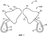
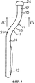
На фиг.1 и фиг.2 схематически показано устройство 10 для защиты слуха. На фиг.1 и фиг.2 показано левое устройство 10L для применения в левом ухе и правое устройство 10R для применения в правом ухе. Левое устройство 10L является зеркальным отражением правого устройства 10R.1 and 2 schematically show a
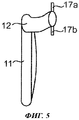
Устройство 10 содержит удлиненный стержень 11 и ручку 12. Стержень 11 и ручка 12 могут быть выполнены, например, как единое целое из соответствующего пластического материала. Ручка 12 может быть, например, маркирована для того, чтобы определять, предназначено ли устройство 10 для применения в левом ухе или в правом ухе.The
Согласно фиг.1 стержень 11 присоединяется к ушному вкладышу 13 для ввода в ушной канал, как более подробно описано ниже. Согласно одному варианту осуществления изобретения ушной вкладыш может быть отсоединен и заменен. Альтернативно этому ушной вкладыш 13 может иметь неразъемное соединение со стержнем 11. Ушной вкладыш 13 может быть выполнен, например, в виде одного или более фланцев, выступающих радиально из стержня 11. Ушной вкладыш 13 может быть выполнен, например, из гибкого материала, в частности из вспененного пластмассового или какого-либо иного пригодного пластмассового или каучукового материала.According to figure 1, the
Стержень 11 содержит соединительную часть 14 для соединения с ручкой 12, крепежную часть 15 для прикрепления к ушному вкладышу 13 и промежуточную часть 16, которая расположена между соединительной частью 14 и крепежной частью 15. Стержень 11 может иметь, например, некоторую конусность в направлении крепежной части 15. Согласно показанному варианту осуществления изобретения крепежная часть 15 содержит по меньшей мере один радиальный выступ 17 для взаимодействия с ушным вкладышем, при этом ушной вкладыш 13 образует соединение с крепежной частью 15 стержня 11. В показанном варианте осуществления изобретения крепежная часть 15 снабжена первым выступом 17а, имеющим первое направление, и вторым выступом 17b, имеющим противоположное направление. Так, например, выступы 17а, 17b имеют противоположные направления в вертикальной плоскости во время применения устройства 10. Согласно одному альтернативному варианту осуществления изобретения крепежная часть 15 снабжена также другими выступами, в частности, перпендикулярными первому выступу 17а и второму выступу 17b, которые не показаны на чертежах.The
Ручка 12 предназначена для удержания между большим и указательным пальцами пользователя. В показанном варианте осуществления изобретения ручка 12 выполнена в виде пластины, расположенной, по существу, в первой плоскости. Первая плоскость соответствует, например, по существу, вертикальной плоскости. Ручка 12 имеет, например, такое же направление, как первый выступ 17а и второй выступ 17b крепежной части 15. Ручка 12 в показанном варианте осуществления изобретения имеет вогнутую контактную поверхность 18 для контактирования с большим пальцем пользователя. Ручка 12 может иметь, например, выпуклую контактную поверхность для контактирования с указательным пальцем пользователя, при этом обратная сторона выпуклой контактной поверхности ручки 12 представляет собой вогнутую контактную поверхность 18. Вогнутая контактная поверхность 18 может быть, например, маркирована для того, чтобы определять, предназначено ли устройство 10 для левого или в правого уха.The
Ручка 12 расположена под углом к стержню 11, поэтому центральная ось А ручки 12 образует угол с центральной осью В стержня 11 в соединительной части 14. Угол α образован в плоскости ручки 12, т.е., в первой плоскости, при этом стержень 11 во время применения проходит наискось вверх от ручки 12. Угол α соответствует, по существу, углу наклона нормального ушного канала. Таким образом, угол α превышает 90° и составляет, например, 100°-150°, предпочтительно 105°-140°, 110°-130°, 115°-125°, 115°-120° или примерно 117°-118°.The
В показанном варианте осуществления изобретения ушной вкладыш 13 имеет закругленную вершину 19 и более широкое основание 20. Альтернативно этому ушной вкладыш является цилиндрическим.In the shown embodiment, the
На фиг.3 и фиг.4 стержень 11 и ручка 12 показаны более подробно. Стержень 11 имеет первую криволинейную часть 21, которая создает изгиб стержня 11 в первом направлении, и вторую криволинейную часть 22, которая создает изгиб стержня 11 во втором направлении для того, чтобы создать наклон вперед промежуточной части 16 и, таким образом, облегчить ввод ушного вкладыша в ушной канал. Первая криволинейная часть 21 расположена между соединительной частью 14 и промежуточной частью 16. Вторая криволинейная часть 22 расположена между крепежной частью 15 и промежуточной частью 16. Первая криволинейная часть 21 выполнена таким образом, чтобы промежуточная часть 16 имела наклон вперед относительно соединительной части 14, при этом во время применения промежуточная часть 16 проходит наискось вверх и вперед относительно ручки 12 или соединительной части 14. Вторая криволинейная часть 22 может быть выполнена, например, таким образом, чтобы крепежная часть 15 была расположена, по существу, параллельно соединительной части 14 или ручке 12. При этом стержень 11 выполнен так, чтобы крепежная часть 15 была смещена относительно ручки 12 или соединительной части 14. Так, например, крепежная часть 15 может проходить во второй плоскости, смещенной относительно первой плоскости, чтобы во время применения крепежная часть 15 была смещена вперед относительно ручки 12 и чтобы первый выступ 17а и второй выступ 17b крепежной части 15 находились во второй плоскости. При этом первая плоскость может быть, например, по существу, параллельной второй плоскости. Альтернативно этому вторая плоскость может быть расположена под углом к первой плоскости.In figure 3 and figure 4, the
Благодаря первой криволинейной части 21 промежуточная часть 16 образует первый угол β с соединительной частью 14 и благодаря второй криволинейной части 22 - второй угол γ с крепежной частью 15, таким образом, промежуточная часть 16 имеет наклон назад относительно крепежной части 15, когда крепежная часть 15 соединяется с ушным вкладышем 13, установленным в ушном канале. Первый угол β образован в первом направлении, а второй угол γ - во втором направлении, противоположном первому направлению. Первый угол β, например, превышает 90°, поэтому промежуточная часть 16 имеет наклон вперед относительно соединительной части 14. Первый угол β может составлять, например, 100-170°, 110-160°, 120-150°, 130-140° или примерно 135°. Второй угол γ может, например, соответствовать первому углу β, поэтому крепежная часть 15 расположена, по существу, параллельно соединительной части 14. Альтернативно этому крепежная часть 15 имеет наклон относительно соединительной части 14. Второй угол γ может составлять, например, 100-170°, 110-160°, 120-150°, 130-140° или примерно 135°. Поэтому центральная ось В стержня 11 изогнута таким образом, что центральная ось соединительной части 14 стержня 11 смещена радиально в боковом направлении относительно центральной оси В крепежной части 15 стержня. Так, например, боковое смещение С между центральной осью В соединительной части 14 и центральной осью В крепежной части составляет 2-20 мм, 3-15 мм, 4-10 мм, 5-8 мм или примерно 6-7 мм. Центральная ось соединительной части 14 расположена, например, в первой плоскости, в то время как центральная ось В крепежной части 15 расположена во второй плоскости, и при этом вторая плоскость расположена на расстоянии С от первой плоскости. Промежуток С расположен между первой плоскостью и второй плоскостью. Первая и вторая плоскости расположены, по существу, вертикально, когда ушной вкладыш введен в ушной канал, при этом отрезок С расположен, по существу, горизонтально. Центральная ось В крепежной части 15 смещена относительно центральной оси В соединительной части 14 как в горизонтальном, так и в вертикальном направлении.Thanks to the first
Ручка 12 имеет длину D, равную, например, 5-30 мм или около 10-20 мм. Стержень 11 имеет длину Е от ручки или первого конца стержня до центра промежуточной части 16. При этом длина Е включает соединительную часть 14, первую криволинейную часть 21 и половину промежуточной части 16. Кроме того, стержень 11 имеет длину F от центра промежуточной части 16 до второго конца стержня 11. Длина F включает половину промежуточной части 16, вторую криволинейную часть 22 и крепежную часть 15. Длина Е может быть, например, равна длине F. Длина Е может составлять, например, 5-20 мм или около 10 мм, при этом длина F составляет 5-20 мм или около 10 мм. Общая длина стержня 11 составляет, например, 10-30 мм, 15-25 мм или около 20 мм. Общая длина стержня 11 и ручки 12 составляет, например, 20-60 мм, 30-50 мм, 35-45 мм или около 40 мм.The
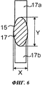
На фиг.5 и фиг.6 показана конструкция стержня 11 согласно одному варианту осуществления настоящего изобретения. Стержень 11 или по меньшей мере крепежная часть 15 стержня 11 имеет овальное или эллиптическое поперечное сечение для того, чтобы предотвратить поворот ушного вкладыша, соединенного с крепежной частью 15 вокруг центральной оси В указанной крепежной части 15. Поэтому поперечное сечение крепежной части 15 имеет короткую ось X и длинную ось Y. Длинная ось Y проходит, например, по существу, в том же самом направлении, что и первый выступ 17а и второй выступ 17b, а также в том же самом направлении, что и ручка 12. При использовании устройства 10 длинная ось Y, первый выступ 17а, второй выступ 17b и ручка 12 проходят, например, по существу, вертикально.FIG. 5 and FIG. 6 illustrate the construction of a
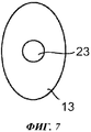
На фиг.7 показан ушной вкладыш 13 согласно одному варианту осуществления изобретения. Ушной вкладыш 13 имеет овальное или эллиптическое поперечное сечение, соответствующее крепежной части 15. Поэтому периферическая или боковая поверхность ушного вкладыша 13 является овальной или эллиптической для того, чтобы улучшить удобство и защиту во время применения. В показанном варианте осуществления изобретения ушной вкладыш 13 имеет выемку 23 для ввода крепежной части 15, при этом крепежную часть 15 можно вставить в выемку 23, чтобы соединить ушной вкладыш 13 со стержнем 11. Выемка 24 может быть, например, круглой, эллиптической, овальной или иметь любую другую пригодную форму. В варианте осуществления, в котором выемка 23 является овальной или эллиптической, она проходит в том же самом направлении, что и эллиптическое поперечное сечение ушного вкладыша 13. Таким образом, когда ушной вкладыш 13 соединяется со стержнем 11, длинная ось ушного вкладыша 13 и длинная ось выемки 23 параллельны длинной оси Y поперечного сечения крепежной части 15. При этом овальное поперечное сечение ушного вкладыша 13 расположено параллельно овальному поперечному сечению выемки 23 и крепежной части 15. Во время применения овальная или эллиптическая форма ушного вкладыша 13 расположена, по существу, в том же самом направлении, что и ручка 12, т.е., по существу, вертикально.7 shows an
На фиг.8 и фиг.9 показан альтернативный вариант осуществления изобретения, в котором крепежная часть 15 содержит радиально выступающий фланец 24, предназначенный для соединения с ушным вкладышем 13. Фланец 24 расположен, например, на втором конце стержня 11. Фланец 24 может проходить, например, вокруг периферии крепежной части 15.On Fig and Fig.9 shows an alternative embodiment of the invention, in which the mounting
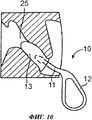
На фиг.10 схематически показан вид сзади ушного канала 25 и устройства согласно одному варианту осуществления изобретения. Вид сзади показывает, что ушной канал 25 имеет наклон вверх. Для того чтобы облегчить ввод ушного вкладыша 13, стержень 11 расположен под углом к ручке 12, как описано со ссылкой на фиг.2. Во время ввода ушного вкладыша 13 в ушной канал 25 пользователь держит ручку 12 между большим и указательным пальцами таким образом, чтобы ручка 12 была направлена, по существу, вертикально вниз, при этом длинная ось овального или эллиптического поперечного сечения ушного вкладыша 13 проходит в том же направлении для правильного позиционирования относительно ушного канала 25. Если ушной вкладыш 13 введен правильно, ручка 12 направлена вниз.10 schematically shows a rear view of the
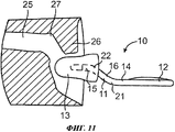
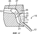
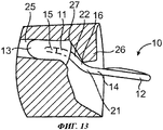
На фиг.11 показан вид сверху ушного канала 25. Как указано, на фиг.11 ушной канал 25 имеет криволинейную форму из-за козелка 26, поэтому часть 28 ушного канала 25 имеет наклон вперед. Во время ввода ушного вкладыша 13 в ушной канал 25 пользователь держит ручку 12 и вставляет стержень 11 с ушным вкладышем 13 в отверстие ушного канала. Затем пользователь наклоняет ручку 12 назад, перемещая стержень 11 и ушной вкладыш 13, таким образом, ушной вкладыш можно подвести к криволинейному участку 27 ушного канала 25, при этом козелок 26 препятствует дальнейшему вводу в ушной канал 25, как показано на фиг.12. Затем ручку 12 наклоняют вперед, чтобы провести ушной вкладыш через козелок 26 и через криволинейный участок 27 ушного канала 25 и расположить в удобной и безопасной позиции в ушном канале 25, как показано на фиг.13.In Fig.11 shows a top view of the
Claims (14)
Applications Claiming Priority (3)
| Application Number | Priority Date | Filing Date | Title |
|---|---|---|---|
| SE1050875A SE536034C2 (en) | 2010-08-26 | 2010-08-26 | Device for hearing protection |
| SE1050875-2 | 2010-08-26 | ||
| PCT/SE2011/050977 WO2012026864A1 (en) | 2010-08-26 | 2011-08-04 | Device for hearing protection |
Publications (2)
| Publication Number | Publication Date |
|---|---|
| RU2013110869A RU2013110869A (en) | 2014-10-10 |
| RU2577458C2 true RU2577458C2 (en) | 2016-03-20 |
Family
ID=45723675
Family Applications (1)
| Application Number | Title | Priority Date | Filing Date |
|---|---|---|---|
| RU2013110869/14A RU2577458C2 (en) | 2010-08-26 | 2011-08-04 | Hearing protection device |
Country Status (7)
| Country | Link |
|---|---|
| US (1) | US8556024B2 (en) |
| EP (1) | EP2608755B1 (en) |
| CN (1) | CN103068349B (en) |
| AU (1) | AU2011293937B2 (en) |
| RU (1) | RU2577458C2 (en) |
| SE (1) | SE536034C2 (en) |
| WO (1) | WO2012026864A1 (en) |
Families Citing this family (7)
| Publication number | Priority date | Publication date | Assignee | Title |
|---|---|---|---|---|
| US8413663B2 (en) * | 2011-02-04 | 2013-04-09 | Moldex Metric, Inc. | Push-in type of earplug with improved insertion stem |
| GB2504303B (en) * | 2012-07-24 | 2016-01-06 | Tobias Murray Bateson | Earphones and earplugs |
| US8550207B1 (en) * | 2012-07-31 | 2013-10-08 | Hundred to One Technology, LLC | High retention aural transmission device |
| US9763832B2 (en) * | 2013-04-10 | 2017-09-19 | Howard S. Leight | Pull out earplug |
| GB2605132A (en) * | 2021-03-18 | 2022-09-28 | Well Uri | Improvements in earplugs |
| US12172090B2 (en) * | 2022-04-13 | 2024-12-24 | Davis Allen Jolly | Game controller handles |
| EP4702953A1 (en) * | 2024-08-29 | 2026-03-04 | Loop | An ear plug |
Citations (2)
| Publication number | Priority date | Publication date | Assignee | Title |
|---|---|---|---|---|
| EP1276443B1 (en) * | 2000-04-06 | 2006-03-22 | Bacou-Dalloz AB | Earplug |
| RU62811U1 (en) * | 2006-10-10 | 2007-05-10 | Валерий Павлович Зяблов | DEVICE FOR INSULATION FROM EXTERNAL SOUND EXPOSURE DURING SLEEP AND ALLOWING TO HEAR A CONDITIONED TARGET SIGNAL |
Family Cites Families (11)
| Publication number | Priority date | Publication date | Assignee | Title |
|---|---|---|---|---|
| US2717596A (en) * | 1954-04-26 | 1955-09-13 | John S Knight | Cushion mounting for mass impedance resonance filter |
| US5074375A (en) * | 1989-10-18 | 1991-12-24 | Grozil Richard S | Hearing protection system assembly |
| USD375551S (en) * | 1994-04-15 | 1996-11-12 | Cabot Safety Intermediate Corporation | Hearing protective earplug |
| CN2292545Y (en) * | 1997-03-19 | 1998-09-30 | 沈宇峰 | Ear plug capable of preventing carsickness |
| US6695093B1 (en) * | 2000-01-13 | 2004-02-24 | Aearo Company | Earplug |
| CN2543314Y (en) * | 2002-06-11 | 2003-04-02 | 李秉彧 | Headphone Structure Improvement |
| US20080181441A1 (en) | 2005-10-11 | 2008-07-31 | Smith Richard C | Adjustable length ear insert |
| US7464786B2 (en) * | 2004-06-11 | 2008-12-16 | Cabot Safety Intermediate Corporation | High sound attenuating hearing protection device |
| US7743771B2 (en) * | 2005-11-09 | 2010-06-29 | 3M Innovative Properties Company | Earplug with articulating stem and locking features |
| US8596279B2 (en) * | 2005-11-09 | 2013-12-03 | 3M Innovative Properties Company | Offset stem for earplug and earplug formed therewith |
| US8413663B2 (en) * | 2011-02-04 | 2013-04-09 | Moldex Metric, Inc. | Push-in type of earplug with improved insertion stem |
-
2010
- 2010-08-26 SE SE1050875A patent/SE536034C2/en unknown
-
2011
- 2011-08-04 US US13/816,848 patent/US8556024B2/en active Active
- 2011-08-04 AU AU2011293937A patent/AU2011293937B2/en active Active
- 2011-08-04 RU RU2013110869/14A patent/RU2577458C2/en active
- 2011-08-04 WO PCT/SE2011/050977 patent/WO2012026864A1/en not_active Ceased
- 2011-08-04 CN CN201180040988.9A patent/CN103068349B/en active Active
- 2011-08-04 EP EP11820252.2A patent/EP2608755B1/en active Active
Patent Citations (2)
| Publication number | Priority date | Publication date | Assignee | Title |
|---|---|---|---|---|
| EP1276443B1 (en) * | 2000-04-06 | 2006-03-22 | Bacou-Dalloz AB | Earplug |
| RU62811U1 (en) * | 2006-10-10 | 2007-05-10 | Валерий Павлович Зяблов | DEVICE FOR INSULATION FROM EXTERNAL SOUND EXPOSURE DURING SLEEP AND ALLOWING TO HEAR A CONDITIONED TARGET SIGNAL |
Also Published As
| Publication number | Publication date |
|---|---|
| SE1050875A1 (en) | 2012-02-27 |
| EP2608755B1 (en) | 2018-05-30 |
| AU2011293937A1 (en) | 2013-03-21 |
| RU2013110869A (en) | 2014-10-10 |
| EP2608755A1 (en) | 2013-07-03 |
| AU2011293937B2 (en) | 2014-07-31 |
| US20130161121A1 (en) | 2013-06-27 |
| CN103068349B (en) | 2015-09-02 |
| WO2012026864A1 (en) | 2012-03-01 |
| SE536034C2 (en) | 2013-04-09 |
| EP2608755A4 (en) | 2014-06-18 |
| US8556024B2 (en) | 2013-10-15 |
| CN103068349A (en) | 2013-04-24 |
Similar Documents
| Publication | Publication Date | Title |
|---|---|---|
| RU2577458C2 (en) | Hearing protection device | |
| CN106659864B (en) | Head-wearing tool clamping device | |
| US11146880B2 (en) | Skirt attachment | |
| CN102065806B (en) | Bandless hearing protector and method | |
| CN212231703U (en) | Ear-shaped structure | |
| KR20110065518A (en) | Retention Module for Earphones in Hearing Aids | |
| JP4577547B2 (en) | Goggles length adjustment mechanism | |
| GB2458225A (en) | Earbud adapter with increased flexibility region | |
| KR20180086850A (en) | sensor holder for intraoral X-ray sensor | |
| KR101941840B1 (en) | Intraoral sensor and sensor indicator, and intraoral radiographic system including same | |
| US8083022B2 (en) | Receiver support and earmold for a hearing device as well as use of a thermoplast for manufacturing an earmold | |
| JP2008515299A (en) | Hearing aid adapter | |
| JP7105011B2 (en) | Jaw angle holding aid and jaw angle correction device including the same | |
| JP2025514439A (en) | Bone Plate Mounting Assembly | |
| EP3731536A1 (en) | Auricular structure using skirt attachment | |
| CN223054438U (en) | Handle shell of endoscope, endoscope handle and endoscope | |
| AU2012238227B9 (en) | Face protector for fastening to safety goggles | |
| US12506993B2 (en) | Earphone | |
| JP2005515736A (en) | hearing aid | |
| KR102122121B1 (en) | Bracket unit for orthodontics | |
| CN101843112A (en) | Auscultation type earphone | |
| KR102844330B1 (en) | Endoscopic Mouthpiece with Enhanced Procedural Convenience | |
| KR20230127811A (en) | Sound apparatus having eartip with improved comfort of wearing | |
| JP3108344U (en) | Nostril cannula | |
| JP2003135379A (en) | Two-channel endoscope |