RU2575218C2 - Press-fitting - Google Patents
Press-fitting Download PDFInfo
- Publication number
- RU2575218C2 RU2575218C2 RU2013128098/06A RU2013128098A RU2575218C2 RU 2575218 C2 RU2575218 C2 RU 2575218C2 RU 2013128098/06 A RU2013128098/06 A RU 2013128098/06A RU 2013128098 A RU2013128098 A RU 2013128098A RU 2575218 C2 RU2575218 C2 RU 2575218C2
- Authority
- RU
- Russia
- Prior art keywords
- press
- crimping
- sleeve
- pipe
- ring
- Prior art date
Links
- 238000002788 crimping Methods 0.000 claims description 120
- 238000007906 compression Methods 0.000 claims description 26
- 238000003780 insertion Methods 0.000 claims description 13
- 230000002093 peripheral Effects 0.000 claims description 7
- 238000000034 method Methods 0.000 abstract description 4
- 230000000694 effects Effects 0.000 abstract description 2
- 238000010327 methods by industry Methods 0.000 abstract 1
- 239000000126 substance Substances 0.000 abstract 1
- 238000009434 installation Methods 0.000 description 12
- 230000000875 corresponding Effects 0.000 description 9
- 238000003825 pressing Methods 0.000 description 4
- 230000000007 visual effect Effects 0.000 description 4
- 210000001847 Jaw Anatomy 0.000 description 3
- 238000006073 displacement reaction Methods 0.000 description 3
- 239000000463 material Substances 0.000 description 3
- 230000003993 interaction Effects 0.000 description 2
- 239000000203 mixture Substances 0.000 description 2
- 230000003287 optical Effects 0.000 description 2
- 238000007789 sealing Methods 0.000 description 2
- 229910001369 Brass Inorganic materials 0.000 description 1
- 230000037250 Clearance Effects 0.000 description 1
- 210000001503 Joints Anatomy 0.000 description 1
- 238000005452 bending Methods 0.000 description 1
- 230000000903 blocking Effects 0.000 description 1
- 239000010951 brass Substances 0.000 description 1
- 230000035512 clearance Effects 0.000 description 1
- 239000002131 composite material Substances 0.000 description 1
- 238000010276 construction Methods 0.000 description 1
- 230000001276 controlling effect Effects 0.000 description 1
- 230000001419 dependent Effects 0.000 description 1
- 238000005315 distribution function Methods 0.000 description 1
- 239000000789 fastener Substances 0.000 description 1
- 238000010438 heat treatment Methods 0.000 description 1
- 238000005286 illumination Methods 0.000 description 1
- 238000007689 inspection Methods 0.000 description 1
- 239000002184 metal Substances 0.000 description 1
- 230000003252 repetitive Effects 0.000 description 1
- 230000011218 segmentation Effects 0.000 description 1
- 229910001220 stainless steel Inorganic materials 0.000 description 1
- 239000010935 stainless steel Substances 0.000 description 1
- XLYOFNOQVPJJNP-UHFFFAOYSA-N water Substances O XLYOFNOQVPJJNP-UHFFFAOYSA-N 0.000 description 1
Images


Abstract
Description
Настоящее изобретение относится к компрессионным фитингам или пресс-фитингам и в частности к кольцам для визуальной индикации обжатия. Также настоящее изобретение относится к применению таких фитингов для прессования и способу обжима.The present invention relates to compression fittings or press fittings, and in particular to rings for visual indication of crimping. The present invention also relates to the use of such compression fittings and a crimping method.
Компрессионные фитинги, также называемые пресс-фитингами, позволяющие соединять трубы за счет приложения усилия сжатия и деформации при использовании одной или двух гильз, хорошо известны в области прокладки и монтажа труб, укладки труб и монтажа трубопроводных систем, например, для воды, газа или обогрева.Compression fittings, also called press fittings, which allow pipes to be connected by applying compression and deformation forces when using one or two sleeves, are well known in the field of pipe laying and installation, pipe laying and installation of piping systems, for example, for water, gas or heating .
Пресс-фитинги используют для соединения не только металлических труб, но также и пластиковых труб или композитных труб металл-пластик. Их используют для соединения соответствующим образом расположенных частей труб при использовании соединительных частей, одним концом установленных на концы соединяемых труб, где их затем подвергают деформации, или обжимают, или прессуют. Затем их закрепляют в определенных зонах, например, при использовании пресс-гильз на соединяемых частях при использовании так называемой системы обжимного инструмента, которая, как правило, имеет сменные обжимные губки.Press fittings are used to connect not only metal pipes, but also plastic pipes or metal-plastic composite pipes. They are used to connect appropriately arranged pipe parts using connecting parts, with one end mounted on the ends of the pipes to be joined, where they are then subjected to deformation, or crimped, or pressed. Then they are fixed in certain areas, for example, when using press sleeves on the connected parts when using the so-called crimping tool system, which, as a rule, has replaceable crimping jaws.
Трубную, трубопроводную или труботранспортную систему собирают в несколько стадий: сначала трубы вставляют в фитинги и затем фитинги обжимают для гарантии хорошей механической прочности и герметичности монтажа. Обжим по существу представляет прессование монтажной гильзы, также указанной как обжимная гильза, что вызывает деформацию или формование трубы вокруг фитинга, в который она вставлена. Как правило, давление прилагается к фитингу при использовании в качестве обжимного инструмента обжимных губок. Эти обжимные губки прилагают радиальное давление к материалу фитинга для приведения его во взаимодействие с поверхностью труб(ы) / для соединения труб(ы), достигая, таким образом надежного соединения и надежной герметичности.A pipe, pipeline or pipeline system is assembled in several stages: first, the pipes are inserted into the fittings and then the fittings are crimped to ensure good mechanical strength and tight installation. The crimp is essentially the pressing of a mounting sleeve, also referred to as a crimping sleeve, which causes the pipe to warp or form around the fitting into which it is inserted. Typically, pressure is applied to the fitting when using crimping jaws as a crimping tool. These crimping jaws apply radial pressure to the fitting material to bring it into contact with the surface of the pipe (s) / to connect the pipe (s), thereby achieving a reliable connection and reliable tightness.
В зависимости от трубопроводов используют изогнутые пресс-фитинги, угловые пресс-фитинги или Т-образные, как правило, с одним, двумя или тремя местами соединений.Depending on the piping, curved press fittings, angle press fittings or T-shaped are used, usually with one, two or three connection points.
Монтаж или обслуживание трубной, трубопроводной или труботранспортной системы требует сборки множества труб и пресс-фитингов. Очень важно, чтобы каждое соединение при монтаже было должным образом обжато для гарантии хорошей механической прочности и герметичности монтажа всей системы или всей установки. В противном случае могут возникнуть серьезные проблемы с безопасностью, в частности, в случае газопроводных систем. При сборке такой трубопроводной системы необходимо множество пресс-фитингов для соединения отдельных секций трубы. Существует риск того, что пресс-соединение может быть пропущено среди других отдельных частей соединения. При монтаже в строящихся зданиях, где часто происходит загрязнение и не очень хорошая видимость или освещенность, такие пресс-фитинги к тому же плохо визуально различимы.Installation or maintenance of a pipe, pipeline or piping system requires the assembly of multiple pipes and press fittings. It is very important that each connection is properly crimped during installation to ensure good mechanical strength and tight installation of the entire system or the entire installation. Otherwise, serious safety problems may arise, in particular in the case of gas pipeline systems. When assembling such a piping system, many press fittings are needed to connect the individual pipe sections. There is a risk that the press joint may be missed among other separate parts of the joint. When mounting in buildings under construction, where pollution often occurs and not very good visibility or illumination, such press fittings are also poorly visually distinguishable.
Иногда трудно гарантировать, что все соединения были собраны и обжаты должным образом. Это может происходить из-за условий работы (например, плохое освещение) или из-за повторяющихся стадий во время монтажа, что может оказать негативное влияние на тщательную проверку каждого соединения.It is sometimes difficult to ensure that all joints have been assembled and crimped properly. This may be due to operating conditions (for example, poor lighting) or due to repetitive steps during installation, which may have a negative effect on the thorough inspection of each connection.
Ввиду того что, на первый взгляд, фитинг и секция трубы соединены, и обычно кажется, что они установлены герметично, иногда забывают обеспечить или провести конечный обжим под положительным давлением и неопределяемый обжим. Даже последующая опрессовка готовой трубопроводной системы не всегда позволяет обнаружить пропуск обжима соединения, в частности, в случаях газовых линий существует риск того, что соединения с пропущенным обжимом останутся незамеченными. Это может привести к значительным последующим убыткам.Due to the fact that, at first glance, the fitting and the pipe section are connected, and it usually seems that they are installed tightly, sometimes they forget to provide or carry out the final crimp under positive pressure and undetectable crimp. Even subsequent pressure testing of the finished pipeline system does not always allow one to detect a missing crimp connection, in particular, in the case of gas lines, there is a risk that connections with a missed crimp will go unnoticed. This may result in significant subsequent losses.
Такие пресс-фитинги широко известны, и уже были описаны различные способы, как не забыть провести обжим соединения или как лицу, проводящему монтаж, проверить, что фитинги были корректно обжаты. В этом отношении, в частности, следует указать EP 1790896 A1 и DE 20013425 U1.Such press fittings are widely known, and various methods have already been described, how to remember to crimp the connection, or as the installer, to verify that the fittings have been crimped correctly. In this regard, in particular, EP 1790896 A1 and DE 20013425 U1 should be mentioned.
Пример маркировочного кольца или кольцеобразного элемента описан в EP 1790896, кольцо имеет такую конструкцию, что разрушается при приложении давления во время обжима, обеспечивая, таким образом, визуальную индикацию проведения должного обжима. Однако иногда сегменты разрушенного кольца застревают в обжимном инструменте, вызывая заклинивание инструмента. Дополнительно, оба, как перемещение кольца, так и возможное взаимодействие между обжимным инструментом и секцией трубы, в результате могут привести к повреждению секции трубы, и также, в частности, существует риск того, что край обжимной гильзы может быть поврежден или будет прилагать неадекватное давление.An example of a marking ring or ring-shaped element is described in EP 1790896, the ring is designed so that it breaks when pressure is applied during crimping, thus providing a visual indication of the proper crimping. However, sometimes segments of the broken ring get stuck in the crimping tool, causing the tool to jam. Additionally, both the movement of the ring and the possible interaction between the crimping tool and the pipe section can result in damage to the pipe section, and also, in particular, there is a risk that the edge of the compression sleeve may be damaged or inadequate pressure .
В документе DE 20013425 U1 описывается индикатор-кольцо, расположенное на расстоянии от края обжимной гильзы. Здесь также существует риск повреждения, возникающий из-за непосредственного примыкания секции трубы, и нет гарантии, что край будет должным образом обжат.DE 200 13 425 U1 describes an indicator ring located at a distance from the edge of the crimp sleeve. There is also a risk of damage arising from the direct abutment of the pipe section, and there is no guarantee that the edge will be properly crimped.
Объект настоящего изобретения относится к пресс-фитингу с улучшенными средствами визуальной индикации, где ясно видно, что сборка проведена должным образом без риска повреждения примыкающей трубы.An object of the present invention relates to a press fitting with improved visual display means, where it is clearly seen that the assembly was carried out properly without the risk of damage to the adjacent pipe.
Другой объект настоящего изобретения относится к способу обжима, при котором ясно видно, что лицо, выполняющее операцию, провело обжим должным образом.Another object of the present invention relates to a crimping method in which it is clearly seen that the person performing the operation has crimped properly.
Для достижения этих целей настоящее изобретение предлагает пресс-фитинг, обладающий признаками, изложенными в независимом пункте формулы 1. Предпочтительные варианты воплощения настоящего изобретения приведены в зависимых пунктах формулы изобретения.To achieve these goals, the present invention provides a press fitting having the features set forth in the
В частности, настоящее изобретение относится к пресс-фитингу, имеющему кольцеобразный элемент, который по существу совмещен с торцом, обращенным к трубе, или открытым концом фитинга. В результате в первое время кольцеобразный элемент выполняет подходящим образом несколько функций. Функция указания на проведение обжима известна, но несомненным преимуществом является то, что элемент-индикатор расположен на наиболее удаленном крае, откуда он не может быть перемещен, поскольку это единственное расположение, при котором может быть гарантирован должным образом обжим края.In particular, the present invention relates to a press fitting having an annular element that is substantially aligned with the end facing the pipe or the open end of the fitting. As a result, for the first time, the annular element performs suitably several functions. The crimp indication function is known, but the undoubted advantage is that the indicator element is located at the most distant edge, from where it cannot be moved, since this is the only location at which crimping the edge can be guaranteed properly.
Дополнительная функция состоит в обеспечении перманентного оптического контроля обжимного инструмента, посредством которого край инструмента может быть простым образом совмещен с краем пресс-фитинга.An additional function is to provide permanent optical control of the crimping tool, through which the edge of the tool can be easily combined with the edge of the press fitting.
Другая дополнительная функция состоит в обеспечении распределения усилия или в том, что кольцеобразный элемент расположен между частями, передающими усилие. Это может быть поддержано по меньшей мере за счет локальной орторадиальной деформируемости, то есть деформируемости, ориентированной по существу перпендикулярно к радиальному, наряду с аксиальным направлением. Другими словами, по существу преимущественным является создание кольцеобразного элемента таким образом, чтобы он адаптировался к изменениям периферийных радиусов. Таким образом, это огромное отличие от известного ранее, обжимная гильза на торце, обращенном к трубе, деформируется при использовании многофункционального кольцеобразного элемента, и в результате неожиданно простым образом примыкающая секция трубы одновременно может быть эффективно защищена от повреждения, поскольку, с одной стороны, обжимной инструмент визуально контролируется и таким образом взаимодействие может быть просто исключено, и с другой стороны, кольцеобразный элемент остается в обжимном инструменте и расположен между ним и пресс-гильзой или обжимной гильзой, снижая, таким образом, риск заклинивания или блокировку. В то же самое время обжим края обжимной гильзы может быть улучшен, поскольку, например, даже если обжимной инструмент загрязнен, деформация достигается за счет идеально коаксиальной поверхности, например внутренняя поверхность секций кольцеобразных сегментов.Another additional function is to ensure the distribution of force or that the annular element is located between the parts that transmit the force. This can be supported at least due to local orthoradial deformability, that is, deformability oriented essentially perpendicular to the radial along with the axial direction. In other words, it is essentially advantageous to create an annular element in such a way that it adapts to changes in peripheral radii. Thus, this is a huge difference from the previously known, the crimp sleeve on the end facing the pipe is deformed when using the multifunctional ring-shaped element, and as a result, the unexpectedly adjacent pipe section can be effectively protected from damage at the same time, since, on the one hand, the crimp the tool is visually controlled and thus the interaction can be simply eliminated, and on the other hand, the ring-shaped element remains in the crimping tool and is located between m and a press sleeve or crimp sleeve, thereby reducing the risk of jamming or blocking. At the same time, the crimping of the edge of the crimping sleeve can be improved, because, for example, even if the crimping tool is dirty, deformation is achieved due to the perfectly coaxial surface, for example, the inner surface of the sections of the ring-shaped segments.
Согласно по существу предпочтительному варианту воплощения настоящего изобретения обеспечен пресс-фитинг для соединения труб или присоединения труб, где обжимная гильза обеспечена на торце, обращенном к трубе, кольцеобразным элементом, последний обеспечен и предназначен для взаимодействия с обжимным инструментом для контроля обжимного инструмента и для изменений в его внешнем виде после осуществления заранее заданного воздействия обжимного инструмента.According to a substantially preferred embodiment of the present invention, there is provided a press fitting for connecting pipes or connecting pipes, wherein a crimp sleeve is provided at the end facing the pipe with an annular element, the latter being provided and designed to interact with the crimping tool to control the crimping tool and to change its appearance after the implementation of a predetermined exposure to the crimping tool.
Преимущественно пресс-фитинг включает корпус фитинга с опорным элементом фитинга, на который может быть вставлен конец трубы, обжимную гильзу, которая окружает опорный элемент фитинга. Обжимная гильза имеет такую конфигурацию, чтобы деформироваться при обжиме, закрепляя конец трубы на опорном элементе фитинга. При этом кольцеобразный элемент расположен на открытом конце обжимной гильзы и имеет такую конфигурацию, что передает на обжимную гильзу прилагаемое обжимным инструментом давление. Следовательно, кольцеобразный элемент обеспечен и предназначен для передачи на пресс-гильзу усилий, которые воздействуют на кольцеобразный элемент в области торца, обращенного к трубе, при приложении усилия обжимным инструментом.Advantageously, the press fitting includes a fitting body with a support element of the fitting onto which the end of the pipe can be inserted, a crimp sleeve that surrounds the support element of the fitting. The crimp sleeve is configured to deform when crimped, securing the end of the pipe to the fitting support element. In this case, the ring-shaped element is located on the open end of the crimp sleeve and has such a configuration that it transfers pressure to the crimp sleeve applied by the crimping tool. Therefore, the ring-shaped element is provided and designed to transmit forces to the press sleeve that act on the ring-shaped element in the region of the end face facing the pipe when a crimping tool is applied.
Кольцеобразный элемент может иметь такую конфигурацию, чтобы передавать обжимное давление на обжимную гильзу, выступая при этом в роли индикатора во время обжима. Кольцеобразный элемент преимущественно может быть обеспечен и предназначен для контроля обжимного инструмента таким образом, что края обжимного инструмента и пресс-гильзы совмещены. В качестве альтернативы или дополнительно, кольцеобразный элемент может быть или может оставаться по меньшей мере частично видимым по меньшей мере в течение большей части времени при приложении усилия обжимным инструментом.The ring-shaped element may be configured to transmit crimp pressure to the crimp sleeve while acting as an indicator during crimping. An annular element can advantageously be provided and designed to control the crimping tool in such a way that the edges of the crimping tool and the press sleeve are aligned. Alternatively or additionally, the annular element may or may remain at least partially visible for at least most of the time when a crimping tool is applied.
Преимущественно кольцеобразный элемент обеспечен и предназначен для перманентной деформации или разрушения под воздействием соответствующего обжимного инструмента. Перманентная деформация или разрушаемость гарантирует, что кольцеобразный элемент может быть использован только однократно. В частности, предел перманентной деформации может быть установлен относительно близко к деформационному усилию обжимной гильзы и по существу преимущественно обеспечивает различные предельные показатели деформации, распространенной в различных направлениях.Advantageously, an annular element is provided and is intended for permanent deformation or fracture under the influence of a corresponding crimping tool. Permanent deformation or destructibility ensures that the annular element can be used only once. In particular, the limit of permanent deformation can be set relatively close to the deformation force of the crimp sleeve and essentially preferentially provides various ultimate indicators of deformation distributed in different directions.
Согласно предпочтительному варианту воплощения настоящего изобретения кольцеобразный элемент обеспечен и предназначен для перманентной деформации или разрушения в орторадиальном направлении под воздействием соответствующего обжимного инструмента. Преимущественно кольцеобразный элемент содержит множество орторадиально деформируемых областей, которые должны быть по существу равномерно распределены.According to a preferred embodiment of the present invention, an annular element is provided and is intended for permanent deformation or fracture in the orthoradial direction under the influence of a corresponding crimping tool. Advantageously, the annular element comprises a plurality of orthoradially deformable regions, which should be substantially uniformly distributed.
По существу предпочтительная деформация пресс-гильзы происходит, когда кольцеобразный элемент обеспечен и предназначен под воздействием соответствующего обжимного инструмента для уменьшения радиуса кривизны до радиуса пресс-гильзы и/или он имеет сегменты, имеющие радиус кривизны пресс-гильзы перед деформацией. Также можно обеспечить, чтобы внутренняя поверхность по меньшей мере секций кольцеобразного элемента по существу соответствовала радиусу кривизны примыкающей секции трубы.A substantially preferred deformation of the press sleeve occurs when the annular element is provided and designed by applying a suitable crimping tool to reduce the radius of curvature to the radius of the press sleeve and / or it has segments having a radius of curvature of the press sleeve before deformation. It can also be ensured that the inner surface of at least the sections of the annular element substantially matches the radius of curvature of the adjacent pipe section.
Преимущественно кольцеобразный элемент может быть уплотнен со стороны обжимного инструмента и/или со стороны трубы. Таким образом, по существу легко увидеть визуально перманентную деформацию и уплотнение со стороны трубы, что также делает возможным деформацию края точно по существу вдоль линейного контура.Advantageously, the annular element may be sealed on the crimp tool side and / or on the pipe side. Thus, it is essentially easy to see visually permanent deformation and sealing from the side of the pipe, which also makes it possible to deform the edges exactly essentially along a linear contour.
Для того чтобы получить максимально равномерную и, таким образом, герметичную деформацию, предпочтительно, чтобы перед деформацией по меньшей мере половина, предпочтительно более чем две трети и по существу предпочтительно по меньшей мере 90% внутренней периферийной поверхности кольцеобразного элемента контактировало с торцом пресс-гильзы, обращенным к трубе.In order to obtain the most uniform and thus hermetic deformation, it is preferable that at least half, preferably more than two-thirds and essentially preferably at least 90% of the inner peripheral surface of the annular element contact the end of the press sleeve before deformation. facing the pipe.
Преимущественно кольцеобразный элемент должен предохранять от аксиального передвижения для того, чтобы еще больше уменьшить риск заклинивания во время деформации.Advantageously, the annular element should be protected against axial movement in order to further reduce the risk of jamming during deformation.
Также настоящее изобретение относится к новому применению такого фитинга, как изложено в приложенной формуле изобретения. Новое в применении состоит в том, что торцевая часть, обращенная к трубе, приводится в тесный контакт с трубой за счет приложения усилия и за счет расположенных между ними частей кольцевого элемента, функционирующего в качестве элемента, распределяющего усилие. Неожиданно могут были достигнуты оба параметра, как гарантия герметичности системы, так и, с другой стороны, минимизация риска повреждения, поскольку концевая зона фактически впрессована в материал трубы и, таким образом, отсутствуют выступающие заусенцы, которые часто встречались ранее.The present invention also relates to a new use of such a fitting as set forth in the attached claims. New in application is that the end part facing the pipe is brought into close contact with the pipe due to the application of force and due to the parts of the ring element located between them, which functions as a force distributing element. Unexpectedly, both parameters could be achieved, both guaranteeing the tightness of the system and, on the other hand, minimizing the risk of damage, since the end zone is actually pressed into the pipe material and, therefore, there are no protruding burrs that were often encountered earlier.
Применение пресс-фитинга, в частности пресс-фитинга, как указано выше, обеспечивает контроль обжимного инструмента на торце пресс-гильзы, обращенном к трубе, и эта кромка деформируется за счет расположенных между ними передающих усилие кольцеобразных сегментов, действуя как контроль или по меньшей мере содействуя обеспечению указанного контроля.The use of a press fitting, in particular a press fitting, as described above, provides control of the crimping tool at the end of the press sleeve facing the pipe, and this edge is deformed due to the ring-shaped segments transmitting the force between them, acting as a control or at least helping to ensure that control.
Таким образом, в отличие от предшествующего уровня техники по существу желательно, чтобы кольцеобразный элемент принимал участие в деформации, в противоположность немецкой промышленной модели, описанной в документе DE 20013425 U1, требующей, чтобы кольца-индикаторы не оказывали воздействия или не загрязняли обжимной инструмент. Во всех других известных из предшествующего уровня техники устройствах и применениях целью также было отсутствие деформации самого торца, обращенного к трубе, даже если иногда упоминается расположение в концевой зоне, никогда не рассматривалось применение для целей деформации элемента, который предназначен для того, чтобы отметить или указать деформацию или надлежащий обжим. Вместо этого всегда предпринимались попытки обеспечить разрушаемость или разрушение на части таким образом, чтобы было возможно удалить фрагменты максимально быстро или предусматривалось перемещение в аксиальном направлении для передвижения элемента из зоны действия. В предшествующем уровне техники предполагалось, что необходимо избегать контакта с большей частью периметра для гарантии разрушаемости в любом случае, даже если разрушение в заданных точках отсутствует, как в документе EP 1790896 A1, при расположении за пределами обжимного инструмента.Thus, in contrast to the prior art, it is essentially desirable for the annular element to take part in the deformation, in contrast to the German industrial model described in DE 20013425 U1 requiring that the indicator rings do not affect or contaminate the crimping tool. In all other devices and applications known from the prior art, the goal was also to not deform the end itself facing the pipe, even if the location in the end zone is sometimes mentioned, the use of an element that is intended to mark or indicate has never been considered deformation or proper crimping. Instead, attempts have always been made to ensure destructibility or destruction to parts in such a way that it is possible to remove fragments as quickly as possible or provide for movement in the axial direction to move the element out of range. In the prior art, it was assumed that contact with most of the perimeter should be avoided to guarantee destructibility in any case, even if there is no destruction at predetermined points, as in EP 1790896 A1, when located outside the crimping tool.
Предпочтительно при использовании фитинга кольцеобразные сегменты по настоящему изобретению соединены вместе кольцеобразно перед деформацией пресс-гильзы, и после деформации лежат отделенными друг от друга и от обжимной гильзы. Таким образом, когда обжимной инструмент отсоединяют и удаляют после проведения стадии обжима, прессования или приложения усилия сжатия, кольцеобразные сегменты просто отпадают от инструмента, при этом, как указано выше, во время процесса обжима они остаются в инструменте, где они контролируют инструмент и принимают участие в деформации.Preferably, when using the fitting, the annular segments of the present invention are joined together annularly before deformation of the press sleeve, and after deformation lie separate from each other and from the crimp sleeve. Thus, when the crimping tool is disconnected and removed after the crimping, pressing or compression step is applied, the ring-shaped segments simply fall off the tool, while, as mentioned above, during the crimping process they remain in the tool where they control the tool and take part in deformation.
Впервые настоящее изобретение комбинирует различные функции в кольцеобразном элементе, установленном на краю пресс-гильзы, и преимущественно защищенном от аксиального смещения, а именно с функцией индикации, функцией оптического контроля и функцией распределения усилия.For the first time, the present invention combines various functions in an annular element mounted on the edge of the press sleeve and which is predominantly protected against axial displacement, namely with an indication function, an optical control function and a force distribution function.
В частности, это может быть достигнуто эффективным способом, если орторадиальная деформируемость будет больше по сравнению с радиальной деформируемостью. По существу преимущественно создана конструкция кольцеобразного элемента таким образом, чтобы прилагаемое усилие в результате приводило к перманентной орторадиальной деформации и к эластичной и/или перманентной деформации секций в радиальном направлении.In particular, this can be achieved in an efficient way if the orthoradial deformability is greater than the radial deformability. Essentially, a ring-shaped element has been advantageously designed in such a way that the applied force results in permanent orthoradial deformation and in elastic and / or permanent deformation of the sections in the radial direction.
Согласно одному варианту воплощения настоящего изобретения кольцеобразный элемент имеет множество сегментов, соединенных со множеством соединительных секций, кольцеобразный элемент имеет такую конфигурацию, что существенно уменьшает окружность при обжиме ввиду орторадиальной деформации соединительных сегментов и одновременного передвижения сегментов по направлению друг к другу.According to one embodiment of the present invention, the ring-shaped element has a plurality of segments connected to a plurality of connecting sections, the ring-shaped element has such a configuration that significantly reduces the circumference during crimping due to the ortho radial deformation of the connecting segments and the simultaneous movement of the segments towards each other.
Предпочтительно каждый сегмент имеет контрольную зону на своем конце, каждый конец формирует контрольную зону, соединяющуюся с концом, формирующим контрольную зону примыкающего сегмента, и имеющую конфигурацию для работы с концом, формирующим контрольную зону примыкающего сегмента.Preferably, each segment has a control zone at its end, each end forms a control zone that connects to an end forming a control zone of an adjacent segment and configured to operate with an end forming a control zone of an adjacent segment.
Каждый конец, формирующий контрольную зону, преимущественно по существу может совпадать по форме с концом, формирующим контрольную зону, с которым его соединяют.Each end forming the control zone can advantageously substantially coincide in shape with the end forming the control zone to which it is connected.
Согласно одному варианту воплощения настоящего изобретения каждый конец, формирующий контрольную зону, по существу имеет такую же форму, как конец, формирующий контрольную зону, с которым его соединяют, таким образом, что два соединенных конца совпадают друг с другом во время обжима.According to one embodiment of the present invention, each end forming the control zone is substantially the same as the end forming the control zone with which it is connected, so that the two connected ends coincide with each other during crimping.
Преимущественно соединительные секции могут иметь конфигурацию, позволяющую им разрушаться при приложении достаточного обжимного усилия.Advantageously, the connecting sections may have a configuration that allows them to break when a sufficient crimping force is applied.
Согласно другому варианту воплощения настоящего изобретения открытый конец пресс-гильзы включает фаску для контроля вставки конца трубы.According to another embodiment of the present invention, the open end of the press sleeve includes a chamfer to control the insertion of the end of the pipe.
Кольцеобразный элемент может быть установлен заподлицо с открытым концом обжимной гильзы.The ring-shaped element can be mounted flush with the open end of the crimp sleeve.
Согласно другому варианту воплощения настоящего изобретения кольцеобразный элемент насаживают на открытый конец или на торец трубы, пресс-гильзы или обжимной гильзы и кольцо находит на гильзу, выступая из открытого конца пресс-гильзы в направлении трубы.According to another embodiment of the present invention, the annular element is mounted on the open end or on the end of the pipe, press sleeve or crimp sleeve and the ring is on the sleeve, protruding from the open end of the press sleeve in the direction of the pipe.
Предпочтительно кромка образует фаску для контроля вставки конца трубы.Preferably, the edge forms a chamfer to control the insertion of the end of the pipe.
Также настоящее изобретение относится к применению указанного выше пресс-фитинга, где обжимной инструмент контролируется на открытом конце гильзы за счет деформируемого, разрушаемого кольца, расположенного на открытом конце обжимной гильзы, которое имеет конфигурацию для передачи обжимного усилия на обжимную гильзу.The present invention also relates to the use of the above press fitting, wherein the crimping tool is controlled at the open end of the sleeve by a deformable, destructible ring located at the open end of the crimping sleeve, which is configured to transmit the crimping force to the crimping sleeve.
Также настоящее изобретение относится к способу обжима, включающему приложение обжимного усилия при использовании обжимного инструмента к деформируемому разрушаемому кольцеобразному элементу на открытом конце пресс-гильзы пресс-фитинга, обжимной инструмент и/или сегменты кольцеобразного элемента остаются под контролем, когда кольцеобразный элемент разрушается при приложении обжимного усилия, при этом деформирующее усилие прилагается по и через кольцеобразный элемент на гильзу.The present invention also relates to a crimping method, including applying a crimping force when using a crimping tool to a deformable destructible annular element at the open end of the press sleeve of the press fitting, the crimping tool and / or segments of the annular element remain under control when the annular element is destroyed when the crimp is applied efforts, while the deforming force is applied along and through the annular element to the sleeve.
Другие характеристики и преимущества настоящего изобретения будут более очевидны из приведенного ниже описания некоторых предпочтительных вариантов воплощения настоящего изобретения, приведенных только в качестве примеров со ссылкой на приложенные Фигуры, где:Other characteristics and advantages of the present invention will be more apparent from the following description of some preferred embodiments of the present invention, given only as examples with reference to the attached Figures, where:
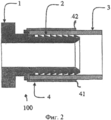
Фигура 1 - вид в поперечном сечении пресс-фитинга перед сборкой и приложением усилия сжатия по первому аспекту настоящего изобретения.Figure 1 is a cross-sectional view of a press fitting before assembly and application of a compressive force according to a first aspect of the present invention.
Фигура 2 - вид в поперечном сечении, соответствующий Фигуре 1, но после сборки и приложения усилия сжатия по первому аспекту настоящего изобретения.Figure 2 is a cross-sectional view corresponding to Figure 1, but after assembly and application of compression force according to the first aspect of the present invention.
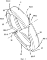
Фигура 3 - кольцо, используемое на пресс-фитинге по первому аспекту настоящего изобретения.Figure 3 is a ring used on a press fitting according to the first aspect of the present invention.
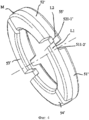
Фигура 4 - часть кольца, используемого в качестве альтернативы на пресс-фитинге по первому аспекту настоящего изобретения.4 is a portion of a ring used alternatively on a press fitting in accordance with a first aspect of the present invention.
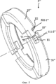
Фигура 5 - часть другого кольца, используемого в качестве альтернативы на пресс-фитинге по первому аспекту настоящего изобретения.Figure 5 is part of another ring used alternatively on the press fitting of the first aspect of the present invention.
Фигура 6 - часть другого кольца, используемого в качестве альтернативы на пресс-фитинге по первому аспекту настоящего изобретения.Figure 6 is part of another ring used alternatively in the press fitting of the first aspect of the present invention.
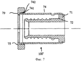
Фигура 7 - изображение пресс-фитинга по другому аспекту настоящего изобретения.Figure 7 is an illustration of a press fitting in another aspect of the present invention.
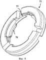
Фигура 8 - вид в поперечном сечении фитинга Фигуры 7.Figure 8 is a cross-sectional view of the fitting of Figure 7.
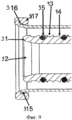
Фигура 9 - вид в поперечном сечении основного корпуса, имеющего конфигурацию, как у пресс-фитинга по одному из аспектов настоящего изобретения.Figure 9 is a cross-sectional view of a main body configured as a press fitting in one aspect of the present invention.
Фигура 10 - описание способа приложения усилия сжатия по одному из аспектов настоящего изобретения, на Фигурах идентичные части указаны под идентичными номерами.Figure 10 is a description of a method of applying compression force in one aspect of the present invention, in the Figures identical parts are indicated by identical numbers.
На Фигуре 1 показан пресс-фитинг 100, позволяющий осуществить соединение трубы 3 по одному из аспектов настоящего изобретения; на Фигуре 2 показан пресс-фитинг 100 после обжима. Для большей наглядности изображение Фигуры 2 упрощено, поэтому деформация от обжима полностью не показана.Figure 1 shows a press fitting 100 allowing
Пресс-фитинг 100 включает корпус фитинга, включающий внутренний поддерживающий элемент 2 с принимающей областью и обжимную или пресс-гильзу 4, которая определяет место установки, куда помещают конец трубы 3.The
Принимающая область 2 расположена от одного конца корпуса 1 в продольном направлении к другому концу корпуса фитинга и предпочтительно дискретна, но может иметь иную конфигурацию. На конце, противостоящем торцу, обращенному к трубе, или открытому концу, принимающая область поддерживающего элемента фитинга имеет ограничитель, который ограничивает глубину вставки трубы 3.The receiving
Пресс-гильза 4 располагается по существу вокруг внутреннего поддерживающего элемента 2 и может деформироваться необратимым образом при приложении усилия сжатия для скрепления внутреннего опорного элемента 2 и вставленного конца трубы 3. Усилие сжатия может быть приложено при использовании пресса, действующего как обжимной инструмент (не показано).The
Пресс-гильза 4 расположена в радиальном пространстве, покрывающем по меньшей мере частично принимающую область или опорный элемент фитинга 2 в продольном направлении корпуса фитинга 1. Хотя также возможна другая конфигурация, предпочтительно оба, и корпус фитинга 1, и пресс-гильза 4, являются осесимметричными и установлены коаксиально. Часть принимающей области 2, которая покрывается пресс-гильзой 4, рассматривается также как пресс-гильза, поскольку только в этой области труба 3 может быть соединена с пресс-фитингом 1.The
На открытом торце 41, обращенном к трубе, также называемой вставляемым концом 41 трубы, пресс-гильза 4 имеет фаску 42. Фаска 42 имеет такую конфигурацию, чтобы контролировать трубу 3 при вставке трубы в гильзу 4 и на внутренний опорный элемент 2 пресс-фитинга 100.On the
Фаска 42 располагается по существу вокруг всей окружности вставляемого конца 41 трубы, придавая вставляемому концу трубы форму, которая по существу расширяется или «имеет раструб».
Корпус фитинга 1 имеет удлиненную конфигурацию вдоль продольной оси и может быть в одной из конфигураций по существу симметричным относительно своей продольной оси.The housing of the
Кольцеобразный элемент или кольцо 5 вставлено в пресс-гильзу 4 на вставляемом конце 6 трубы, то есть на открытом конце или на торце обжимной гильзы, обращенном к трубе. Кольцо 5 перманентно деформируется, в частности разрушается при приложении обжимного усилия, и его конфигурация изменяется таким образом, что визуально указывает на проведение обжима надлежащим образом.An annular element or
Кольцо 5 в данном случае представляет пластиковое кольцо. Оно предпочтительно установлено на торец 6 пресс-гильзы 4, обращенный к трубе, таким образом, что оно находится на одном уровне с торцом пресс-гильзы 4, обращенным к трубе, и в то же самое время его внутренняя периферийная поверхность контактирует с внешней поверхностью пресс-гильзы 4. Для формирования соединения соединяемая труба 3 вставляется в пресс-фитинг в кольцеобразную полость между пресс-фитингом 4 и принимающей областью опорного элемента 2 фитинга до упора в ограничитель на конце принимающей области 2. Пространство между пресс-гильзой 4 и принимающей областью опорного элемента 2 фитинга по существу соответствует толщине стенки трубы 3.
На Фигуре 2 показан пресс-фитинг 1 с трубой 3, вставленной между пресс-гильзой 4 и опорным элементом 2 фитинга, в обжатом или соединенном состоянии. Это определяется тем, что кольцеобразный элемент 5 утрачен, поскольку, как только приложение усилия сжатия успешно проведено, этот кольцеобразный элемент 5 деформируется, ввиду по меньшей мере частичной передачи необходимого усилия сжатия он падает сам или может быть легко удален. Для большей простоты и наглядности индуцируемая деформация на Фигуре не показана.Figure 2 shows a
Далее приведено краткое описание применения по настоящему изобретению. После того как секция трубы отрезана до требуемой длины, трубу 3 вставляют в кольцеобразный зазор между пресс-гильзой 4 и опорным элементом 2 фитинга до упора в ограничитель. В предпочтительном варианте воплощения настоящего изобретения затем при использовании обжимного инструмента проводят обработку кольцеобразного элемента 5 таким образом, что внешняя кривизна совпадает, предпочтительно с минимальным зазором с совпадающей приемной частью обжимного инструмента. Цель состоит в том, чтобы по меньшей мере часть усилия, необходимого для прессования или обжима трубы 3 пресс-фитингом, передавалась через кольцеобразный элемент 5. Таким образом, кольцеобразный элемент 5 принимает участие в процессе приложения усилия сжатия, с одной стороны, контролируя обжимной инструмент, а с другой стороны, принимая участие по меньшей мере частично в обжиме и соединении трубы 3 с пресс-фитингом. Это происходит за счет орторадиальной деформируемости кольцеобразного элемента 5, поскольку во время процесса приложения усилия последний располагается между трубой 3 и обжимным устройством и может участвовать в уменьшении поперечного сечения, вызываемого стадией приложения усилия сжатия, и в процессе остается в перманентном контакте с обоими, и с обжимным инструментом и с пресс-фитингом. Как только обжимной инструмент открывают по окончании процесса приложения усилия сжатия, сегменты кольцеобразного элемента 5 падают, предпочтительно сами собой, но также они могут быть легко удалены без приложения какого-либо значительного усилия из соответствующего углубления обжимного инструмента. Отсутствие кольцеобразного элемента 5 на пресс-фитинге указывает на то, что последний был подвергнут приложению усилия сжатия.The following is a brief description of the use of the present invention. After the pipe section is cut to the required length, the
Как приведено ниже на Фигурах 3-5, кольцеобразный элемент 5 служит не только для указания [надлежащего] обжима, но кольцеобразный элемент 5 также имеет конфигурацию, позволяющую принимать участие в обжиме за счет передачи усилия и контроля обжимного инструмента.As shown below in Figures 3-5, the
На Фигуре 3 приведен кольцеобразный элемент или кольцо 5, которое может быть использовано на пресс-фитинге согласно другому аспекту настоящего изобретения.Figure 3 shows an annular element or
Кольцо 5, как показано на Фигуре 3, имеет четыре сегмента 51, 52, 53, 54, соединенных четырьмя соединительными секциями 55, 56, 57, 58. Сегмент 51 соединен с сегментом 52 соединительной секцией 55 и соединен с сегментом 54 соединительной секцией 58. Сегменты 52 и 53 соединены вместе соединительной секцией 56, а сегменты 53 и 54 соединены вместе при использовании соединительной секции 57.
Сегменты 51, 52, 53, 54 по существу в общем виде имеют форму дуги и имеют конфигурацию, позволяющую прижиматься к поверхности конца для вставки 6 трубы. Каждый из сегментов 51, 52, 53, 54 имеет на концах 511-1, 511-2, 521-1, 521-2, 531-1, 531-2, 541-1, 541-2 контрольные зоны, соответственно соединенные и имеющие конфигурации, позволяющие работать с соответствующими контрольными зонами примыкающего сегмента 51, 52, 53, 54.
Например, сегмент 51 включает конец 511-2, формирующий контрольную зону, присоединенную соединительной секцией 55 к концу 521-1, формирующему контрольную зону сегмента 52. Сегмент 51 включает другой конец 511-1, формирующий контрольную зону, присоединенную соединительной секцией 58 к концу 541-2, формирующему контрольную зону сегмента 54. Сегмент 52 также включает конец 521-2, формирующий контрольную зону, присоединенную соединительной секцией 56 к концу 531-1, формирующему контрольную зону сегмента 53. Сегмент 53 включает другой конец 531-2, формирующий контрольную зону, присоединенную соединительной секцией 57 к концу 541-1, формирующему контрольную зону сегмента 54.For example,
Каждый конец, формирующий контрольную зону каждого сегмента, предпочтительно имеет форму, совпадающую с концом, формирующим контрольную зону, с которой он будет взаимодействовать. Как приведено на Фигуре 3, концы, формирующие контрольные зоны, имеют фаски, расположенные по диагонали к аксиальной плоскости кольца 5.Each end forming the control zone of each segment preferably has a shape matching the end forming the control zone with which it will interact. As shown in Figure 3, the ends forming the control zone have chamfers located diagonally to the axial plane of
Соединительные секции 55, 56, 57, 58 имеют такую конфигурацию, которая предусматривает деформацию вплоть до разрушения при орторадиальном напряжении сдвига в результате приложения усилия сжатия обжимным инструментом. Орторадиальная деформация означает деформацию прежде всего вдоль оси, которая по существу ортогональна обеим осям, и радиальной, и аксиальной (продольной) оси пресс-фитинга.The connecting
Длина соединительных секций предпочтительно выбрана таким образом, чтобы разрушение произошло только при достаточном приложении усилия сжатия, соответствующем усилию сжатия, требуемому для надлежащего обжима, которое приложено к кольцу 5. Это предотвращает разрушение кольца до того, как будет приложено надлежащее усилие сжатия.The length of the connecting sections is preferably selected so that failure occurs only with sufficient application of compression force corresponding to the compression force required for proper crimping, which is applied to the
Следовательно, во время обжима обжимной инструмент поддерживается кольцом-индикатором 5, которое насажено на пресс-гильзу 4 на конце для вставки 6 трубы. Давление, прилагаемое обжимным инструментом, вызывает существенное уменьшение окружности кольца-индикатора 5 за счет орторадиальной деформации соединительных секций 55, 56, 57, 58 и одновременного вращательного передвижения концов, формирующих контрольные зоны, по направлению друг к другу.Therefore, during crimping, the crimping tool is supported by an
Соединительные секции 55, 56, 57, 58 подвергают сильному орторадиальному напряжению сдвига, который вызывает разрушение соединительных секций и кольца 5 на четыре сегмента по окончанию обжима, указывая, таким образом, визуально на то, что обжим проведен надлежащим образом. Кольцо 5 имеет конфигурацию, позволяющую контролируемое разрушение за счет разрушения соединенных секций или взаимосоединяющих секций между сегментами, составляющими кольцо.The connecting
Специалисту в области техники, к которой относится настоящее изобретение, понятно, что сегменты 51, 52, 53, 54, которые остаются на поверхности вставляемого конца 6 трубы, имеют конфигурацию, позволяющую осуществлять передачу обжимного усилия на гильзу 4. Дополнительно, совпадающая форма концов каждого соединяемого друг с другом сегмента позволяет контролировать сегменты и обжимной инструмент. Это преимущественно предотвращает разрушение фрагментов сегмента или соединительных секций, которые могут вызвать заклинивание обжимного инструмента или вызвать случайную или неэффективную деформацию фитинга или другого фитинга, обжатого позже.The person skilled in the art to which the present invention relates, it is understood that the
Специалисту в области техники, к которой относится настоящее изобретение, понятно, что кольцо приведено с четырьмя сегментами. Количество сегментов обеспечено только для примера и не является ограничивающим.One skilled in the art to which the present invention relates will understand that a ring is provided with four segments. The number of segments is provided by way of example only and is not limiting.
Кольцо 5 предпочтительно произведено из пластика. Корпус фитинга предпочтительно произведен из латуни или пластика, при этом гильза на каждом конце фитинга может быть произведена из нержавеющей стали или аналогичного материала.
На Фигуре 4 приведено кольцо 5′, используемое на пресс-фитинге согласно другому аспекту настоящего изобретения. Кольцо 5′, приведенное на Фигуре 4, имеет четыре сегмента 51′, 52′, 53′, 54′, соединенных четырьмя соединительными секциями 55′, 56′, 57′, 58′. Сегмент 51′ соединен с сегментом 52′ соединительной секцией 55′ и соединен с сегментом 54′ соединительной секцией 58′. Сегменты 52′ и 53′ соединены вместе соединительной секцией 56′, а сегменты 53′ и 54′ соединены вместе соединительной секцией 57′.Figure 4 shows a 5 ′ ring used on a press fitting in accordance with another aspect of the present invention. The
Только соединительная секция 55′ соединяет два сегмента 51′, 52,′ как указано далее. Специалисту в области техники, к которой относится настоящее изобретение, понятно, что соединения между другими сегментами идентичны соединению сегментов 51′ и 52′, как указано ниже.Only the connecting
Сегмент 51′ соединен с сегментом 52′ соединительной секцией 55′. Сегмент 51′ включает конец 511-2′, формирующий контрольную зону, соединенную соединительной секцией 55′ с концом 521-1′, формирующим контрольную зону сегмента 52′.
Как приведено на Фигуре 4, концы 511-2′ и 521-1′, формирующие контрольные зоны, имеют совпадающую форму. Конец 511-2′ имеет внешний выступ L1 шириной менее чем половина ширины сегмента 51′, который расположен на окружности кольца на стороне кольца, обращенной к трубе. Конец 521-1″ также имеет внутренний выступ L2, шириной менее чем половина ширины сегмента 52′, который расположен на окружности кольца на стороне кольца, обращенной к фитингу. Два выступа L1, L2 попарно соединены друг с другом соединительной секцией 55′, расположенной вдоль оси по существу перпендикулярной или по диагонали к выступам L1, L2. Два выступа L1, L2 предпочтительно имеют конфигурацию и размер, позволяющие совмещаться по аксиальной оси один рядом с другим, во время обжима и после этого соединительная секция 55′ разрушается, конец 511-2′, расположенный противоположно выступу L2, образует ограничитель для выступа L2, а конец 521-1′, расположенный противоположно выступу L1, образует ограничитель для выступа L1.As shown in Figure 4, the ends 511-2 ′ and 521-1 ′ forming the control zones have a matching shape. The end 511-2 ′ has an external protrusion L1 with a width of less than half the width of the
Следовательно, во время обжима давление, прилагаемое обжимным инструментом, вызывает существенное уменьшение окружности кольца-индикатора 5′, деформацию соединительной секции 55′ и одновременное вращательное передвижение выступов L1, L2 по направлению друг к другу до того момента, когда соединительная секция 55′ разрушится и остановится на соответствующих противоположных концах сегмента каждого выступа L1, L2.Therefore, during crimping, the pressure applied by the crimping tool causes a significant decrease in the circumference of the
Следует отметить, что выступы L1, L2 имеют аксиальную толщину менее чем или равную половине аксиальной толщины кольца 5′, другими словами, соответствующие углубления находятся по существу на одном уровне с или выше срединной плоскости М кольца. Это предотвращает увеличение кольца в размерах из-за материала, оставшегося после разрушения соединительной секции 55′. Конечно, выступы могут иметь варьирующую ассиметричную аксиальную толщину у различных взаимосоединительных секций или различную ширину или узость углублений при условии разрушения взаимосоединительных секций в результате передвижения выступов по направлению друг к другу.It should be noted that the protrusions L1, L2 have an axial thickness less than or equal to half the axial thickness of the
На Фигуре 5 приведено в аксиальной плоскости два сегмента 51″, 52", соединенных друг с другом соединительной секцией 55" кольца 5″, используемого на пресс-фитинге согласно другому варианту воплощения настоящего изобретения. На Фигуре 5 приведен другой пример соединения кольцевых сегментов.The Figure 5 shows in axial plane two
Сегмент 51″ соединен с сегментом 52″ соединительной секцией 55′. Сегмент 51″ включает конец 511-2″, формирующий контрольную зону, соединенный соединительной секцией 55" с концом 521-1″, формирующим контрольную зону сегмента 52″.
Как приведено на Фигуре 5, концы 511-2″ и 521-1", формирующие контрольные зоны, имеют совпадающую форму. Конец 521-1″ включает центральное углубление Е1, расположенное вдоль окружности кольца. Конец 521-1″ включает центральный выступ Е2, противолежащий углублению Е1, его ширина по существу меньше, чем ширина углубления Е1. Углубление Е1 и выступ Е2 соединены друг с другом соединительной секцией 55", включающей две секции T1, Т2 расположенные вдоль оси по существу перпендикулярной или по диагонали к углублению Е1 и выступу Е2. Секции Т1 и Т2 предпочтительно имеют конфигурацию, позволяющую располагаться от периферического конца углубления Е1 по существу к середине выступа Е2. Выступ Е2 предпочтительно имеет форму и размер, которые позволяют подходить углублению Е1 во время вращения, вызывания приложения сдвигового усилия к кольцу во время обжима.As shown in Figure 5, the ends 511-2 ″ and 521-1 ″ forming the control zones have a matching shape. The end 521-1 ″ includes a central recess E1 located along the circumference of the ring. The end 521-1 ″ includes a central protrusion E2, opposite the recess E1, its width is substantially smaller than the width of the recess E1. The recess E1 and the protrusion E2 are connected to each other by a connecting
На Фигуре 6 приведено другое присоединенное кольцо 56, используемое на пресс-фитинге по другому аспекту настоящего изобретения.Figure 6 shows another attached
Кольцо 56, приведенное на Фигуре 6, имеет четыре сегмента 651, 652, 653, 654, соединенные четырьмя соединительными секциями 655, 656, 657, 658. Сегмент 651 соединен с сегментом 652 соединительной секцией 655 и соединен с сегментом 654 соединительной секцией 658. Сегменты 652 и 653 соединены вместе соединительной секцией 656, а сегменты 653 и 654 соединены вместе соединительной секцией 657.The
Сегменты по существу в общем виде имеют форму дуги и имеют конфигурацию, позволяющую прижиматься к поверхности вставляемого конца 6 трубы. Каждый из сегментов 651, 652, 653, 654 имеет на концах 6511-1, 6511-2, 6521-1, 6521-2, 6531-1, 6531-2, 6541-1, 6541-2 контрольные зоны, соответственно соединенные и имеющие конфигурации, позволяющие работать с соответствующими контрольными зонами примыкающего сегмента 651, 652, 653, 654.The segments are essentially general in the form of an arc and have a configuration that allows it to be pressed against the surface of the inserted end 6 of the pipe. Each of
Только соединительная секция 655 соединяет два сегмента 651, 652 как указано далее. Специалисту в области техники, к которой относится настоящее изобретение, понятно, что соединения между другими сегментами будут такими же, как таковые между сегментами 651 и 652.Only the connecting
Сегмент 651 соединен с сегментом 652 соединительной секцией 655. Сегмент 651 включает конец 6511-2, формирующий контрольную зону, прикрепленную соединительной секцией 655 к концу 6521-1, формирующему контрольную зону сегмента 652.
Как приведено на Фигуре 6, концы 6511-2 и 6521-1, формирующие контрольные зоны, имеют совпадающую форму. Конец 6511-2 имеет нижний выступ L1, расположенный вдоль окружности кольца на внутреннем периметре кольца, его ширина меньше, чем половина радиальной толщины сегмента 651. Конец 6521-1 имеет верхний выступ L2, расположенный вдоль окружности кольца на внешнем периметре кольца, его ширина меньше, чем половина радиальной толщины сегмента 652.As shown in Figure 6, the ends 6511-2 and 6521-1, forming the control zone, have a matching shape. End 6511-2 has a lower protrusion L1 located along the circumference of the ring on the inner perimeter of the ring, its width is less than half the radial thickness of
Два выступа L1, L2 попарно соединены друг с другом соединительной секцией 655. Соединительная секция 655 проходит вдоль оси по существу перпендикулярно или по диагонали к выступам L1, L2. Два выступа LI, L2 предпочтительно имеют форму и размер, позволяющие совпадать при радиальном наложении друг на друга вдоль радиальной оси во время обжима, после чего соединительная секция 655 разрушается. Конец 6511-2 противолежит выступу L2, образует ограничитель для выступа L2, а конец 6521-1 противолежит выступу L1, образует ограничитель для выступа L1.The two protrusions L1, L2 are pairwise connected to each other by the connecting
На Фигуре 7 приведен пресс-фитинг 100', позволяющий соединить трубу 3 по одному из аспектов настоящего изобретения.The Figure 7 shows a press fitting 100 ', allowing to connect the
Пресс-фитинг 100′ включает корпус фитинга 71, включающий внутренний опорный элемент фитинга 72 и пресс-гильзу 74, определяющую пространство вставки, в которое вставляют конец трубы 73.The press fitting 100 ′ includes a
Пресс-гильза 74 расположена по существу вокруг внутреннего опорного элемента фитинга 72 корпуса фитинга и может быть необратимо деформирована при приложении усилия сжатия для того, чтобы запереть опорный элемент фитинга 72 и вставляемый конец трубы 73. Приложение усилия сжатия может быть осуществлено при использовании тисков или обжимного инструмента (не показано).The
Пресс-гильза 74 имеет на открытом торце 741, обращенном к трубе, также называемом вставляемом конце 741 трубы, фаску 742. Фаска 742 имеет конфигурацию, позволяющую контролировать трубу 73 во время установки трубы в кольцо 74 и поверх внутреннего опорного элемента 72 пресс-фитинга 100′.The
Фаска 742 располагается по существу вокруг всей окружности вставляемого конца трубы 741, придавая вставляемому концу трубы форму, которая по существу расширяется или «имеет раструб».
Корпус фитинга 71 имеет удлиненную конфигурацию вдоль продольной оси и может иметь конфигурацию по существу симметричную относительно своей продольной оси.The housing of the fitting 71 has an elongated configuration along the longitudinal axis and may have a configuration substantially symmetrical about its longitudinal axis.
Кольцо 75 вставляется или закрепляется на пресс-гильзе 74 в области вставляемого конца 6 трубы.The
Как приведено на Фигуре 8, крепежные средства 76, 77 обеспечены для того, чтобы гарантировать, что кольцо по существу останется на гильзе во время транспортировки и технологической обработки.As shown in FIG. 8, fastening means 76, 77 are provided to ensure that the ring substantially remains on the sleeve during transport and processing.
Крепежные средства включают внутренние аксиальные выступающие части 76 и внешние аксиальные выступающие части 77. Внешние аксиальные выступающие части 76 имеют конфигурацию, позволяющую прижиматься аксиально к внешнему концу фаски 742 со стороны вставки трубы. Внутренние аксиальные выступающие части 77 имеют конфигурации, позволяющие прижиматься к внешнему аксиальному концу фаски 742, со стороны фитинга трубы.The fastening means include internal
Следует отметить, что выступающие части 76 и 77 имеют угловое смещение позиций по окружности, что означает, что отсутствует аксиальное совпадение внутренних выступающих частей или, с другой стороны, аксиальное совпадение внешних выступающих частей. Это смещение конфигурации предотвращает повреждение кольца, когда оно помещено на пресс-гильзе 74.It should be noted that the protruding
В альтернативном варианте воплощения настоящего изобретения крепежные средства 76, 77 кольца на гильзе также могут быть сформированы за счет аксиальной внутренней кольцеобразной выступающей части 76 и аксиальной внешней выступающей кольцеобразной части 77 по всей окружности кольца.In an alternative embodiment of the present invention,
Кольцо 75, приведенное на Фигурах 7 и 8, помещенное на пресс-гильзу 74, частично покрывает концевую область гильзы и имеет секцию 79 кольца, частично выступающую за конечную область гильзы по направлению к трубе. Выступающая секция 79 преимущественно увеличивает зону фаски, сформированную самой гильзой. Следовательно, установка трубы 3 в гильзу облегчается двумя способами, как за счет выступающей секции кольца 75, так и за счет фаски 742 пресс-гильзы 4.The
Внутренняя периферическая поверхность выступающей секции 79 и внутренняя периферическая поверхность зоны фаски могут быть совмещены для улучшения установки трубы. Такая конфигурация не приведена на Фигуре 7, где обе поверхности дискретны.The inner peripheral surface of the protruding
В противном случае, кольцо 75 может быть вытолкнуто на гильзу 4, чтобы быть заподлицо с концевой областью гильзы.Otherwise, the
Несмотря на то что кольца, приведенные на Фигурах 3-6, каждое имеет особенную конфигурацию сегментов и контрольных зон, следует отметить, что возможна комбинация вариантов воплощения настоящего изобретения, например кольцо, включающее первую конфигурацию сегментов и контрольных зон по первому варианту воплощения настоящего изобретения, с другой конфигурацией сегментов и контрольных зон и даже наклонных плоскостей согласно другому варианту воплощения настоящего изобретения.Although the rings shown in Figures 3-6 each have a particular configuration of segments and control zones, it should be noted that a combination of embodiments of the present invention is possible, for example a ring including a first configuration of segments and control zones according to the first embodiment of the present invention, with a different configuration of segments and control zones and even inclined planes according to another embodiment of the present invention.
На Фигуре 9 приведен вид в поперечном сечении через основной корпус 91, имеющий конфигурацию как у пресс-фитинга, где пресс-фитинг имеет конструкцию, как у двойной подвижной соединительной муфты, и основной корпус 91 имеет вставляемый конец 92 и опорный элемент фитинга с поверхностью 93, направляющей трубу с профилем 94 наряду с несколькими уплотнительными элементами 95 на поверхности 93, направляющей трубу.Figure 9 shows a cross-sectional view through the main body 91, configured as a press fitting, where the press fitting is designed as a dual movable coupler, and the main body 91 has an
Также можно увидеть, что пресс-гильза 910 коаксиально расположена вокруг поверхности 93, направляющей трубу, образуя, таким образом, кольцеобразный зазор 911 между поверхностью 93, направляющей трубу, и гильзой 910.You can also see that the press sleeve 910 is coaxially located around the
На свободном конце 915 пресс-гильзы 910, который считается вставляемым концом 92, пресс-фитинг дополнительно включает кольцо-индикатор 917 для приложения усилия сжатия, на котором по существу расположен радиально паз 916, в который входит свободный конец 915 пресс-гильзы 910 для создания подвижного соединения между кольцом-индикатором 917 для приложения усилия сжатия и гильзой 910. Как можно видеть, для этого свободный конец 915 гильзы 910 расширен по сравнению с остальной частью гильзы 910. Также легко проследить, когда к гильзе 910 было приложено усилие сжатия, свободный конец 915 гильзы 910 выходит из паза 916 кольца-индикатора 917 для приложения усилия сжатия и, таким образом, не закрывает кольцо-индикатор 917 для приложения усилия сжатия. Кольцо-индикатор 917 для приложения усилия сжатия может иметь заранее определенные точки излома, которые разрушаются при приложении усилия сжатия. Если в процессе кольцо-индикатор 917 для приложения усилия сжатия разрушается до такой степени, что полностью падает с фитинга, то отсутствие кольца-индикатора 917 для приложения усилия сжатия само по себе достаточно для демонстрации того, что соответствующий конец фитинга прошел надлежащий обжим.At the
На Фигуре 10 приведены различные стадии способа обжима согласно одному аспекту настоящего изобретения. Этот способ показан при использовании пресс-фитинга 100, как указано выше, включающего кольцо 5. Конечно, в способе может быть использован пресс-фитинг и другое кольцо, как приведено на Фигурах 3-9.Figure 10 shows the various steps of a crimping method according to one aspect of the present invention. This method is shown using a
На стадии S1 труба 3 вставлена в пресс-фитинг 100 на внутренний опорный элемент 2.In step S1, the
На стадии S2 обжимной инструмент помещен поверх кольца 5 со стороны вставки трубы у открытого конца гильзы.In step S2, the crimping tool is placed on top of the
На стадии S3 прилагают обжимное усилие на кольцо 5, которое передает обжимное усилие через сегменты 51-54 на гильзу 4. Давление, прилагаемое обжимным инструментом, существенно уменьшает окружность кольца-индикатора 5 за счет орторадиальной деформации соединительных секций 55, 56, 57, 58 и за счет одновременного вращательно передвижения навстречу друг другу концов, формирующих контрольные зоны сегментов 51-54, по направлению друг к другу, поддерживая, таким образом, совмещение обжимного инструмента и/или сегментов внутри инструмента.At step S3, a crimping force is applied to the
На стадии S4 соединительные секции 55, 56, 57, 58, подвергаются сильному орторадиальному напряжению сдвига и разрушаются, что в результате приводит к сегментации кольца 5 на четыре сегмента 51, 52, 53, 54 и контролирует обжимной инструмент, когда обжим близится к завершению.At step S4, the connecting
Преимущественно разрушение кольца 5, таким образом, визуально указывает, что обжим проведен должным образом и концы, формирующие контрольные зоны сегментов кольца, помогают направлять сегменты кольца друг к другу и контролировать обжимной инструмент.Advantageously, the destruction of the
Кратко настоящее изобретение относится к пресс-фитингу, снабженному гильзой с разрушаемым кольцом, которое закреплено на конце каждой гильзы, и способу обжима такого пресс-фитинга. Кольцо имеет такую конфигурацию, которая позволяет визуально указывать, что обжим проведен надлежащим образом, наряду с передачей обжимного усилия. Кольцо также может контролировать обжим или обжимной инструмент во время операции обжима. Дополнительно, кольцо полностью участвует в операции обжима. Кольцо расположено на гильзе со стороны конца вставляемой трубы, а не по середине пресс-фитинга. Это преимущество гарантирует хорошее совмещение между гильзой и трубой, предотвращая изгиб, что также улучшает визуальный внешний вид прошедших обжим фитингов.Briefly, the present invention relates to a press fitting provided with a sleeve with a collapsible ring that is attached to the end of each sleeve and a method for crimping such a press fitting. The ring has a configuration that allows you to visually indicate that crimping is carried out properly, along with the transfer of crimping efforts. The ring can also control the crimp or crimping tool during the crimping operation. Additionally, the ring is fully involved in the crimping operation. The ring is located on the sleeve from the end of the inserted pipe, and not in the middle of the press fitting. This advantage ensures good alignment between the sleeve and the pipe, preventing bending, which also improves the visual appearance of the crimped fittings.
Claims (17)
корпус фитинга с опорным элементом фитинга (2), поверх которого может быть вставлен конец трубы (3), пресс-гильза (4), окружающая опорный элемент фитинга, с конфигурацией, позволяющей деформацию при приложении обжимного усилия при использовании обжимного инструмента, для соединения конца трубы (3) с опорным элементом фитинга (2),
деформируемый, разрушаемый кольцеобразный элемент (5), расположенный на открытом конце гильзы, с конфигурацией, позволяющей передавать обжимное усилие на пресс-гильзу (4), кольцеобразный элемент (5) имеет конфигурацию, позволяющую передавать усилия, которые воздействуют на кольцеобразный элемент в области торца (6), обращенного к трубе, во время воздействия обжимного инструмента на компрессионную гильзу, где кольцеобразный элемент (5) имеет конфигурацию, позволяющую разрушение и перманентное состояние деформации, вызванное воздействием обжимного инструмента.2. Press fitting (100, 100 ″) according to claim 1, including:
fitting body with a fitting support element (2), on top of which the pipe end (3) can be inserted, a press sleeve (4) surrounding the fitting support element, with a configuration that allows deformation when a crimping force is applied using a crimping tool to connect the end pipes (3) with a supporting element of the fitting (2),
deformable, destructible ring-shaped element (5) located on the open end of the sleeve, with a configuration that allows you to transfer crimping force to the press sleeve (4), the ring-shaped element (5) has a configuration that allows you to transfer forces that act on the ring-shaped element in the end region (6), facing the pipe, during the impact of the crimping tool on the compression sleeve, where the ring-shaped element (5) has a configuration that allows fracture and a permanent state of deformation caused by the action of imnogo tool.
Applications Claiming Priority (7)
| Application Number | Priority Date | Filing Date | Title |
|---|---|---|---|
| DE202010012981U DE202010012981U1 (en) | 2010-11-24 | 2010-11-24 | Press fitting |
| DE202010012981.8 | 2010-11-24 | ||
| FR1100782A FR2967750B1 (en) | 2010-11-24 | 2011-03-14 | CRIMPING FITTING WITH PERIPHERAL RING |
| FR1100782 | 2011-03-14 | ||
| DE201120101106 DE202011101106U1 (en) | 2011-05-26 | 2011-05-26 | Basic body for a fitting system and a corresponding press or plug-in fitting |
| DE202011101106.6 | 2011-05-26 | ||
| PCT/EP2011/070929 WO2012069584A2 (en) | 2010-11-24 | 2011-11-24 | Press fitting |
Publications (2)
| Publication Number | Publication Date |
|---|---|
| RU2013128098A RU2013128098A (en) | 2014-12-27 |
| RU2575218C2 true RU2575218C2 (en) | 2016-02-20 |
Family
ID=
Citations (5)
| Publication number | Priority date | Publication date | Assignee | Title |
|---|---|---|---|---|
| DE29920371U1 (en) * | 1999-11-19 | 2000-01-20 | Herz Armaturen Gmbh | Connector |
| RU2208737C2 (en) * | 2001-01-12 | 2003-07-20 | Зильберберг Владимир Элюкимович | Permanent joint of end fittings with high-pressure hose |
| DE102004016327A1 (en) * | 2004-03-30 | 2005-11-03 | Geberit Mapress Gmbh | Press-fitting has colored identifier which indicates its purpose, e.g. yellow for gas pipes, identifier being removed after mounting fitting, improving appearance of connection |
| EP1596116A1 (en) * | 2004-05-14 | 2005-11-16 | Comap | Visual indication ring of the pressfitting of a pipe coupling |
| FR2873780A1 (en) * | 2004-07-29 | 2006-02-03 | Comap Sa | VISUALIZATION RING FOR CRIMPING A FITTING FOR TUBES |
Patent Citations (5)
| Publication number | Priority date | Publication date | Assignee | Title |
|---|---|---|---|---|
| DE29920371U1 (en) * | 1999-11-19 | 2000-01-20 | Herz Armaturen Gmbh | Connector |
| RU2208737C2 (en) * | 2001-01-12 | 2003-07-20 | Зильберберг Владимир Элюкимович | Permanent joint of end fittings with high-pressure hose |
| DE102004016327A1 (en) * | 2004-03-30 | 2005-11-03 | Geberit Mapress Gmbh | Press-fitting has colored identifier which indicates its purpose, e.g. yellow for gas pipes, identifier being removed after mounting fitting, improving appearance of connection |
| EP1596116A1 (en) * | 2004-05-14 | 2005-11-16 | Comap | Visual indication ring of the pressfitting of a pipe coupling |
| FR2873780A1 (en) * | 2004-07-29 | 2006-02-03 | Comap Sa | VISUALIZATION RING FOR CRIMPING A FITTING FOR TUBES |
Similar Documents
| Publication | Publication Date | Title |
|---|---|---|
| US5496073A (en) | Disengagement tool for use with a pipe joint assembly | |
| US4260181A (en) | Pipe coupling | |
| RU2404390C2 (en) | Hydraulic coupling | |
| EP2470817B1 (en) | Press-connect fitting with improved grab-ring function | |
| EP0588596B1 (en) | Pipe coupling assembly, also in combination with a disengagement tool | |
| RU2556944C2 (en) | Fitting for pipes connection, in particular flexible pipes | |
| KR20120099237A (en) | Housing type pipe joint | |
| RU2736146C2 (en) | Fitting for connection with tubular element, pipe connection and method of connection of fitting with tubular element | |
| RU2577176C2 (en) | Assembly unit with sealing with lock inserts | |
| CN114729720A (en) | Pipe joint for receiving, retaining and releasing pipes and method of assembling a pipe joint | |
| EP2643624B1 (en) | Press fitting | |
| US11566732B2 (en) | Mechanical joint restraint | |
| KR101452360B1 (en) | Tube Fitting Assembly With Indicating Means Capable of Recognizing by the Sense of Hearing or Touch | |
| RU2575218C2 (en) | Press-fitting | |
| CN116547469A (en) | Pipe connector | |
| CN116490715A (en) | Pipe connector | |
| EP3359859B1 (en) | Pipe fitting assembly | |
| US11703165B2 (en) | Ferrule assembly for conduit fitting | |
| EP3660376B1 (en) | Pipe joint and pipe joint structure | |
| EP3736477A1 (en) | Pipe couplings and uses thereof | |
| US11927286B2 (en) | Crimped end connection for flexible hose | |
| GB2174466A (en) | Pipe coupling | |
| RU2575221C2 (en) | Fitting with integral indicating ring | |
| KR101435576B1 (en) | A Bush and Conduit Connecting Apparatus Having the Same | |
| EP2472158B1 (en) | Flexible coupling with mechanical locking and non-slip device used in said coupling |