RU2574373C2 - Spinal implant, instrument for it and method for spinal implant distraction - Google Patents
Spinal implant, instrument for it and method for spinal implant distraction Download PDFInfo
- Publication number
- RU2574373C2 RU2574373C2 RU2013152379/14A RU2013152379A RU2574373C2 RU 2574373 C2 RU2574373 C2 RU 2574373C2 RU 2013152379/14 A RU2013152379/14 A RU 2013152379/14A RU 2013152379 A RU2013152379 A RU 2013152379A RU 2574373 C2 RU2574373 C2 RU 2574373C2
- Authority
- RU
- Russia
- Prior art keywords
- rotator
- teeth
- spinal implant
- lever
- internal
- Prior art date
Links
- 239000007943 implant Substances 0.000 title claims abstract description 50
- 238000000034 method Methods 0.000 title claims abstract description 10
- 239000003814 drug Substances 0.000 abstract 2
- 230000000694 effects Effects 0.000 abstract 1
- 230000000717 retained effect Effects 0.000 abstract 1
- 239000000126 substance Substances 0.000 abstract 1
- 238000002513 implantation Methods 0.000 description 1
- 238000004519 manufacturing process Methods 0.000 description 1
- 238000001356 surgical procedure Methods 0.000 description 1
Images
Abstract
Description
Настоящее изобретение относится к спинальному имплантату в соответствии с преамбулой пункта 1 формулы изобретения, а также к инструменту для этой цели в соответствии с преамбулой пункта 4 или 5 формулы изобретения и к способу дистракции спинального имплантата в соответствии с преамбулой пункта 8 или пункта 9 формулы изобретения.The present invention relates to a spinal implant in accordance with the preamble of claim 1, as well as to an instrument for this purpose in accordance with the preamble of claim 4 or 5, and to a method for distracting a spinal implant in accordance with the preamble of claim 8 or claim 9.
Из заявки США 7029498 B2 известен дистракционный спинальный имплантат, состоящий из двух U-образных частей, в котором две части удерживаются таким образом, что они перемещаются в осевом направлении относительно друг друга в виде телескопа. На свободных поверхностях U-образной наружной части предусмотрен специальный проход, в который вставляется лапчатый пинцет. Лечащий врач может захватить спинальный имплантат этим лапчатым пинцетом и переместить его в нужное место.U.S. Pat. No. 7,029,498 B2 discloses a distraction spinal implant consisting of two U-shaped parts in which two parts are held in such a way that they move axially relative to each other in the form of a telescope. On the free surfaces of the U-shaped outer part, a special passage is provided in which tab forceps are inserted. The attending physician can grab the spinal implant with this pair of forceps and move it to the desired location.
После установки спинального имплантата пинцет удаляется. Для дистракции спинального имплантата до нужного размера через отверстие U-образной части внутрь спинального имплантата вставляется продолговатый направляющий стержень и ввинчивается в резьбу на наружной части до того, как начнется проталкивание полого зубчатого инструмента по направляющему стержню. Таким образом, зубчатый инструмент проталкивается в спинальный имплантат до тех пор, пока внешние зубья, выполненные на зубчатом инструменте, не начнут взаимодействовать с соответствующими зубьями на внутренней части спинального имплантата. Если теперь вращать зубчатый инструмент вокруг его продольной оси, внутренняя часть спинального имплантата начнет смещаться относительно наружной части.After installing the spinal implant, the tweezers are removed. To distract the spinal implant to the desired size through the hole of the U-shaped part, an elongated guide rod is inserted inside the spinal implant and screwed into the thread on the outer part before the hollow gear tool is pushed along the guide rod. Thus, the toothed instrument is pushed into the spinal implant until the external teeth made on the toothed instrument begin to interact with the corresponding teeth on the inside of the spinal implant. If you now rotate the toothed instrument around its longitudinal axis, the inside of the spinal implant will begin to move relative to the outside.
Весь этот процесс очень труден и требует большой ловкости со стороны хирурга. Поскольку зубчатый инструмент сидит очень свободно на направляющем стержне, может случиться так, что во время дистракции он случайно выскользнет из зацепления с зубьями, поэтому его нужно будет вставлять снова.The whole process is very difficult and requires great dexterity on the part of the surgeon. Since the toothed tool sits very loosely on the guide rod, it may happen that during distraction it accidentally slips out of engagement with the teeth, so it will need to be reinserted.
Из заявки США 2006/0241770 A1 известен спинальный имплантат, в состав которого входит наружный элемент и внутренний элемент, который может перемещаться в осевом направлении, при этом поворотное зубчатое колесо с внутренней резьбой располагается на передней стороне наружного элемента, и эта резьба взаимодействует с наружной резьбой внутреннего элемента. Для того чтобы регулировать в осевом направлении внутренний элемент с помощью наружного элемента, через первое отверстие в наружном и внутреннем элементе в рычажную скважину на внутренней стороне внутреннего элемента вводится соответствующий инструмент с длинным штифтом, при этом зубья, выполненные на инструменте, взаимодействуют с соответствующими зубьями на зубчатом колесе. Если инструмент поворачивается вокруг своей продольной оси, зубчатое колесо перемещается вокруг вертикальной оси спинального имплантата. Внутренний элемент перемещается по резьбе зубчатого колеса в соответствии с шагом резьбы. Такой спинальный имплантат состоит из множества отдельных компонентов, что приводит к удорожанию производства. Многие отдельные компоненты, которые перемещаются относительно друг друга, также вызывают сильное трение и риск заедания. Кроме того, для того, чтобы эффективно использовать инструмент, лечащий врач должен обладать большой ловкостью и вводить инструмент с его штифтами сначала через первое отверстие во внутреннем и наружном элементе, а затем в рычажную скважину на противоположной стороне, где зубья и штифт должны одновременно взаимодействовать с рычажной скважиной или зубьями на зубчатом колесе.U.S. Patent Application 2006/0241770 A1 discloses a spinal implant that includes an outer member and an inner member that can move axially, with a rotary gear with an internal thread located on the front side of the external member, and this thread interacts with the external thread internal element. In order to axially adjust the inner element using the outer element, the corresponding tool with a long pin is inserted into the lever hole on the inner side of the inner element through the first hole in the outer and inner element, while the teeth made on the tool interact with the corresponding teeth on gear wheel. If the tool rotates around its longitudinal axis, the gear moves around the vertical axis of the spinal implant. The inner member moves along the thread of the gear according to the pitch of the thread. Such a spinal implant consists of many individual components, which leads to higher production costs. Many individual components that move relative to each other also cause severe friction and the risk of seizing. In addition, in order to effectively use the tool, the attending physician must have great dexterity and enter the tool with its pins first through the first hole in the inner and outer element, and then into the lever hole on the opposite side, where the teeth and the pin must simultaneously interact with lever hole or gear teeth.
Из ранее опубликованной заявки WO 2011/134457 A1 известен спинальный имплантат с наружным корпусом и с внутренним корпусом, который расположен так, что обеспечивается его осевое перемещение, и в котором выполнена резьба для приема соответствующего инструмента. Инструмент прочно вворачивается в наружный корпус, и его штифт вставляется в продолговатое отверстие в наружном корпусе. По окружности штифта выполнены зубья, которые входят в зацепление с зубьями в продолговатом отверстии. Таким образом, когда штифт вращается, внутренний корпус перемещается в осевом направлении.From a previously published application WO 2011/134457 A1, a spinal implant is known with an outer casing and an inner casing, which is positioned so that its axial movement is ensured and in which a thread is made to receive the corresponding tool. The tool is firmly screwed into the outer casing, and its pin is inserted into the elongated hole in the outer casing. Teeth are made around the circumference of the pin, which engage with the teeth in the oblong hole. Thus, when the pin rotates, the inner housing moves axially.
Исходя из этого, целью настоящего изобретения является разработка спинального имплантата и инструмента, как это упомянуто во введении, чтобы спинальный имплантат мог быть легко и точно имплантирован и чтобы могла быть выполнена его дистракция.Based on this, it is an object of the present invention to provide a spinal implant and instrument, as mentioned in the introduction, so that the spinal implant can be easily and accurately implanted and that its distraction can be performed.
В качестве технического решения для осуществления этой цели предлагается спинальный имплантат типа имплантата, упомянутого во введении, с признаками по пункту 1, инструмент с признаками по пункту 4, и инструмент с признаками по пункту 5, а также способ дистракции спинального имплантата в соответствии с признаками по пункту 8 или 9. Предпочтительные варианты осуществления этого спинального имплантата, этого инструмента и этого способа могут быть получены из соответствующих пунктов формулы изобретения.As a technical solution for this purpose, a spinal implant of the type of implant mentioned in the introduction with the features of paragraph 1, a tool with the features of paragraph 4, and a tool with the features of paragraph 5, and also a spinal implant distraction method in accordance with the features of paragraph 8 or 9. Preferred embodiments of this spinal implant, this instrument and this method can be obtained from the relevant claims.
Преимущество спинального имплантата по настоящему изобретению состоит в том, что при перемещении в разные стороны внутреннего и наружного корпусов обеспечивается быстрая дистракция, поскольку оба корпуса можно перемещать одновременно одним движением руки.An advantage of the spinal implant of the present invention is that when the inner and outer shells are moved in different directions, rapid distraction is achieved, since both shells can be moved simultaneously with one hand movement.
Еще одним преимуществом является то, что точная регулировка спинального имплантата достигается за счет сравнительно большого диапазона.Another advantage is that precise adjustment of the spinal implant is achieved through a relatively large range.
Еще одним преимуществом является то, что благодаря зацеплению с положительной посадкой инструмента с зубьями в стенке также можно выполнить дистракцию внутренним корпусом или внешним корпусом с небольшим усилием, даже уже после имплантации и даже под нагрузкой.Another advantage is that due to engagement with a positive fit of the tool with the teeth in the wall, it is also possible to perform distraction with the inner body or the outer body with little effort, even after implantation and even under load.
Такое двухчастное применение инструмента имеет то преимущество, что внутренний корпус и/или наружный корпус могут перемещаться с большой точностью. Это дает возможность лечащему врачу перемещать только внутренний корпус или только наружный корпус в зависимости от каждой конкретной ситуации.Such a two-part use of the tool has the advantage that the inner case and / or the outer case can be moved with great accuracy. This allows the attending physician to move only the inner case or only the outer case, depending on each specific situation.
В соответствии с предпочтительным примером осуществления настоящего изобретения на внутреннем и на наружном корпусе предусмотрены направляющие средства, которые предотвращают поворот внутреннего корпуса относительно наружного корпуса и одновременно создают осевое направление. Это обеспечивает то преимущество, что окружные силы, возникающие в процессе дистракции, не приводят к повороту внутреннего корпуса.According to a preferred embodiment of the present invention, guiding means are provided on the inner and outer casing that prevent the inner casing from rotating relative to the outer casing and at the same time creating an axial direction. This provides the advantage that the circumferential forces arising during the distraction process do not lead to the rotation of the inner casing.
Преимущество было получено при создании направляющих средств в соответствии с принципом шпунта и паза. Таким образом, например, во внутреннем корпусе вдоль продольной оси выполняется паз, который взаимодействует со шпунтом, выполненным на внутренней стенке наружного корпуса. Благодаря конструкции, включающей паз и шпунт, осуществляется направление внутреннего корпуса на определенную длину спинального имплантата, что надежно предотвращает заклинивание.The advantage was obtained when creating the guide means in accordance with the principle of tongue and groove. Thus, for example, in the inner housing along the longitudinal axis, a groove is made that interacts with a tongue made on the inner wall of the outer housing. Thanks to the design, which includes a groove and a tongue, the inner body is directed to a certain length of the spinal implant, which reliably prevents jamming.
Другие преимущества спинального имплантата по настоящему изобретению, инструмента по настоящему изобретению и способа по настоящему изобретению могут быть получены из прилагаемых чертежей и вариантов осуществления, описанных ниже. Согласно настоящему изобретению упомянутые выше и получившие объяснения особенности также могут быть использованы по отдельности или в любой комбинации друг с другом. Упомянутые варианты осуществления настоящего изобретения не следует рассматривать как исчерпывающий перечень, а лишь в качестве примеров. Ниже дается описание чертежей.Other advantages of the spinal implant of the present invention, the instrument of the present invention and the method of the present invention can be obtained from the accompanying drawings and embodiments described below. According to the present invention, the above-mentioned and explained features can also be used individually or in any combination with each other. Mentioned embodiments of the present invention should not be construed as an exhaustive list, but merely as examples. The following is a description of the drawings.
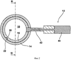
На фиг. 1 показан перспективный вид спинального имплантата по настоящему изобретению и первого варианта осуществления инструмента по настоящему изобретению.In FIG. 1 shows a perspective view of a spinal implant of the present invention and a first embodiment of a tool of the present invention.
На фиг. 2 показан в разрезе вид сверху на спинальный имплантат и инструмент в соответствии с фиг. 1, разрез по линии II-II на фиг. 1.In FIG. 2 is a sectional plan view of a spinal implant and instrument according to FIG. 1, a section along line II-II in FIG. one.
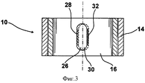
На фиг. 3 показан в разрезе вид сбоку на спинальный имплантат в соответствии с фиг. 1, разрез по линии III-III на фиг. 2.In FIG. 3 shows a sectional side view of a spinal implant according to FIG. 1, a section along line III-III in FIG. 2.
На фиг. 4 показан перспективный вид спинального имплантата в соответствии с фиг. 1 и второго варианта осуществления инструмента по настоящему изобретению.In FIG. 4 shows a perspective view of a spinal implant according to FIG. 1 and a second embodiment of the tool of the present invention.
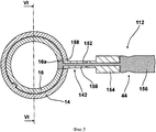
На фиг. 5 показан в разрезе вид сверху на спинальный имплантат в соответствии с фиг. 1 и на инструмент в соответствии с фиг. 4.In FIG. 5 is a cross-sectional top view of a spinal implant according to FIG. 1 and onto the tool in accordance with FIG. four.
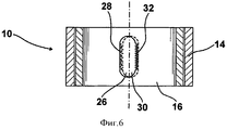
На фиг. 6 показан в разрезе вид сверху на спинальный имплантат в соответствии с фиг. 1, разрез по линии VI-VI на фиг. 5.In FIG. 6 is a cross-sectional top view of a spinal implant according to FIG. 1, a section along line VI-VI in FIG. 5.
На фигурах 1-3 представлен спинальный имплантат 10 по настоящему изобретению и первый вариант осуществления инструмента 12 по настоящему изобретению.Figures 1-3 show a
В состав спинального имплантата входит внешний корпус 14 и внутренний корпус 16, удерживаемый внутри наружного таким образом, чтобы обеспечить его перемещение в осевом направлении, причем в соответствии с представленным здесь вариантом осуществления настоящего изобретения оба корпуса имеют цилиндрическую конструкцию. Направляющие средства 18, которые задают направление при осевом перемещении обоих корпусов 14, 16 и предотвращают поворот корпусов относительно друг друга, выполнены на обоих корпусах 14, 16. Направляющие средства 18 состоят из ориентированного вдоль продольной оси паза 20, выполненного на наружной стороне внутреннего корпуса 16, и шпунта 22, выполненного на внутренней стороне наружного корпуса 14, соответствующего пазу 20.The spinal implant includes an
Во внутреннем корпусе 16 выполнена первая рычажная скважина 26 в виде ориентированного вдоль продольной оси удлиненного отверстия, на вертикальном боку которого образованы зубья в стенке 28. В наружном корпусе 14 выполнена вторая рычажная скважина 30 также в виде ориентированного вдоль продольной оси удлиненного отверстия, на вертикальном боку которого выполнены зубья в стенке 32. Зубья в стенке 28, 32 первой и второй рычажных скважин 26, 30 должны быть предусмотрены на противоположных боковых сторонах рычажных скважин 26, 30.In the
Паз 20, шпунт 22, внутренний корпус 16 и наружный корпус 14 расположены таким образом, что первая рычажная скважина 26 в виде продолговатого отверстия выполнена, по крайней мере, частично заподлицо со второй рычажной скважиной 30 в виде продолговатого отверстия, так что инструмент 12 может быть вставлен через вторую рычажную скважину 30 в первую рычажную скважину 26.The
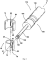
Первый вариант инструмента 12 по настоящему изобретению состоит из стержневого поворотного рычага 42 и ручки 44, прикрепленной к нему. На дистальном конце поворотного рычага 42 выполнены радиально выступающие зубья 46, которые образованы на его поверхности вдоль продольной оси поворотного рычага 42. Зубья 46 образуют зубчатое кольцо. Кроме того, длина каждого зуба 46 позволяет ему входить в зацепление одновременно с соответствующими зубьями в стенке 28 первой рычажной скважины 26 и с соответствующими зубьями в стенке 32 второй рычажной скважины 30 спинального имплантата 10.A first embodiment of the
На фигурах 4-6 представлен второй вариант инструмента 112 по настоящему изобретению, который отличается от первого варианта, представленного на фигурах 1-3, тем, что согласно фигурам 4-6 поворотный рычаг 142 инструмента состоит из двух частей, включая внутренний ротатор 150 и внешний ротатор 152. Ручка 144 также разделена на две части и состоит из внутренней ручки 154 и внешней ручки 156.In figures 4-6 presents a second variant of the
Внутренний ротатор 150 активно соединен с внутренней ручкой 154, а внешняя ручка 156 активно соединена с внешним ротатором 152, так что внутренний ротатор 150 может быть приведен в действие с помощью внутренней ручкой 154, а внешний ротатор 152 может быть приведен в действие с помощью внешней ручки 156. Таким образом, они могут быть использованы независимо друг от друга. С этой целью внутренний ротатор 150 и внутренняя ручка 154 выполнены полыми, так что внешний ротатор 152 находится в этой полости.The
Внутренние зубья 158 и наружные зубья 160, выполненные одинаковой длины, расположены на дистальном конце внутреннего ротатора 150 и на дистальном конце наружного ротатора 152 так, чтобы они выступали в радиальном направлении.The
Во время хирургической операции лечащий врач определяет размер спинального имплантата 10, который будет использоваться. Затем спинальный имплантат вставляют в тело больного в нужном месте. Для дистракции инструмент 12 по первому варианту осуществления настоящего изобретения (фигуры 1-3) вводят в спинальный имплантат таким образом, что зубья 46 проходят в первую рычажную скважину 26, а также во вторую рычажную скважину 30 и входят в зацепление с зубьями в стенке 28, 32. Затем лечащий врач поворачивает ручку 44 инструмента 12 вокруг ее продольной оси. Таким образом, поворотный рычаг 42 вызывает перемещение внутреннего корпуса 16 в одном направлении и смещение наружного корпуса 14 в другом направлении. Так как оба корпуса 14 и 16 могут быть перемещены одним движением руки, дистракция может быть реализована очень быстро и очень точно.During surgery, the attending physician determines the size of the
При использовании инструмента 112, представленного на фигурах 4-6, наружные зубья 160 входят в зацепление с первой рычажной скважиной 26 во внутреннем корпусе 16, а внутренние зубья 158 со второй рычажной скважиной 30 во внешнем корпусе 14. При повороте внутренней ручки 154 внешний корпус 14 перемещается в осевом направлении, или путем поворота внешней ручки 156 внутренний корпус 16 перемещается в осевом направлении.When using the
Claims (7)
в котором на наружном корпусе (14) предусмотрена первая рычажная скважина (26), а на внутреннем корпусе (16) предусмотрена вторая рычажная скважина (30), отличающийся тем, что обе рычажные скважины (26, 30) выполнены в виде продолговатых отверстий, заподлицо по отношению друг к другу, зубья в стенках (28, 32) расположены вдоль продольной оси соответственно первой и второй рычажных скважин (26, 30), при этом зубья в стенках (28, 32) расположены на противоположных боковых сторонах в их соответствующих рычажных скважинах (26, 30), дополнительно предусмотрены направляющие средства (18) на внутреннем (16) и на наружном корпусе (14), которые обеспечивают осевое перемещение внутреннего корпуса (16) относительно наружного корпуса (14), но которые предотвращают поворот внутреннего корпуса (16) относительно наружного корпуса (14).1. A spinal implant with an outer casing (14) and with an inner casing (16) held in it and axially movable,
in which the first lever hole (26) is provided on the outer case (14), and the second lever hole (30) is provided on the inner case (16), characterized in that both lever wells (26, 30) are made in the form of oblong holes, flush with respect to each other, the teeth in the walls (28, 32) are located along the longitudinal axis of the first and second lever wells, respectively (26, 30), while the teeth in the walls (28, 32) are located on opposite lateral sides in their respective lever wells (26, 30), additionally provided holding means (18) on the inner (16) and on the outer casing (14), which provide axial movement of the inner casing (16) relative to the outer casing (14), but which prevent rotation of the inner casing (16) relative to the outer casing (14).
Applications Claiming Priority (3)
| Application Number | Priority Date | Filing Date | Title |
|---|---|---|---|
| DE102011018692.1 | 2011-04-26 | ||
| DE102011018692.1A DE102011018692B4 (en) | 2011-04-26 | 2011-04-26 | Spinal implant, tool and method of distraction of the spinal implant |
| PCT/DE2012/000392 WO2012146231A1 (en) | 2011-04-26 | 2012-04-13 | Spinal implant, tool therefor and method for distracting the spinal implant |
Publications (2)
| Publication Number | Publication Date |
|---|---|
| RU2013152379A RU2013152379A (en) | 2015-06-10 |
| RU2574373C2 true RU2574373C2 (en) | 2016-02-10 |
Family
ID=
Citations (3)
| Publication number | Priority date | Publication date | Assignee | Title |
|---|---|---|---|---|
| RU2063187C1 (en) * | 1992-12-25 | 1996-07-10 | Российский научно-исследовательский нейрохирургический институт им.проф.А.Л.Поленова | Endoprosthesis-distractor |
| RU2225183C2 (en) * | 2001-09-12 | 2004-03-10 | Галикеев Марат Фаритович | Wedging intervertebral distractor device |
| RU2307625C1 (en) * | 2006-01-10 | 2007-10-10 | Государственное образовательное учреждение дополнительного профессионального образования "Новокузнецкий государственный институт усовершенствования врачей Федерального агентства по здравоохранению и социальному развитию" | Arrangement for spondylosyndesis |
Patent Citations (3)
| Publication number | Priority date | Publication date | Assignee | Title |
|---|---|---|---|---|
| RU2063187C1 (en) * | 1992-12-25 | 1996-07-10 | Российский научно-исследовательский нейрохирургический институт им.проф.А.Л.Поленова | Endoprosthesis-distractor |
| RU2225183C2 (en) * | 2001-09-12 | 2004-03-10 | Галикеев Марат Фаритович | Wedging intervertebral distractor device |
| RU2307625C1 (en) * | 2006-01-10 | 2007-10-10 | Государственное образовательное учреждение дополнительного профессионального образования "Новокузнецкий государственный институт усовершенствования врачей Федерального агентства по здравоохранению и социальному развитию" | Arrangement for spondylosyndesis |
Similar Documents
| Publication | Publication Date | Title |
|---|---|---|
| CA2834167C (en) | Spinal implant, tool therefor and method for distracting the spinal implant | |
| US10327918B2 (en) | Height adjustable medical implant | |
| US12440350B2 (en) | Spinal cage devices, systems, and methods of assembly and use | |
| US9149380B2 (en) | Release device for disengaging a medical implant from a catheter and catheter having a release device | |
| US9572678B2 (en) | Tissue spacer implants, insertion and adjustment tools, and method of use | |
| JP2002238929A (en) | Member for being buried into living body inserted between centra of vertebra of backbone and surgical instrument for handling it | |
| US10166111B2 (en) | Spinal implants and related apparatus and methods | |
| ES2395298T3 (en) | Separator for insertion between two vertebrae | |
| US9955959B2 (en) | Rotating retractor arm | |
| AU2017293923B2 (en) | Reamer and guide for glenoid augment preparation | |
| EP2604231B1 (en) | Release mechanism for releasing a medical implant from a catheter, and catheter having a release mechanism | |
| ES2830177T3 (en) | Implant applicators | |
| US20150265321A1 (en) | Instrument for implanting implant device | |
| RU2574373C2 (en) | Spinal implant, instrument for it and method for spinal implant distraction | |
| KR102118034B1 (en) | Surgical curette | |
| JP6389687B2 (en) | Surgical instrument for total knee arthroplasty | |
| AU2007284136B2 (en) | Insertion system for implanting a medical device and surgical methods | |
| EP3493761B1 (en) | Centering device for inserting of a dental implant |