RU2569857C2 - Method of unidirectional solidification of castings and related to this device - Google Patents
Method of unidirectional solidification of castings and related to this device Download PDFInfo
- Publication number
- RU2569857C2 RU2569857C2 RU2010149724/02A RU2010149724A RU2569857C2 RU 2569857 C2 RU2569857 C2 RU 2569857C2 RU 2010149724/02 A RU2010149724/02 A RU 2010149724/02A RU 2010149724 A RU2010149724 A RU 2010149724A RU 2569857 C2 RU2569857 C2 RU 2569857C2
- Authority
- RU
- Russia
- Prior art keywords
- alloy
- mold
- casting
- molten metal
- additional
- Prior art date
Links
Images


Classifications
-
- B—PERFORMING OPERATIONS; TRANSPORTING
- B22—CASTING; POWDER METALLURGY
- B22D—CASTING OF METALS; CASTING OF OTHER SUBSTANCES BY THE SAME PROCESSES OR DEVICES
- B22D7/00—Casting ingots, e.g. from ferrous metals
- B22D7/06—Ingot moulds or their manufacture
-
- B—PERFORMING OPERATIONS; TRANSPORTING
- B22—CASTING; POWDER METALLURGY
- B22D—CASTING OF METALS; CASTING OF OTHER SUBSTANCES BY THE SAME PROCESSES OR DEVICES
- B22D7/00—Casting ingots, e.g. from ferrous metals
- B22D7/02—Casting compound ingots of two or more different metals in the molten state, i.e. integrally cast
-
- B—PERFORMING OPERATIONS; TRANSPORTING
- B22—CASTING; POWDER METALLURGY
- B22D—CASTING OF METALS; CASTING OF OTHER SUBSTANCES BY THE SAME PROCESSES OR DEVICES
- B22D7/00—Casting ingots, e.g. from ferrous metals
- B22D7/06—Ingot moulds or their manufacture
- B22D7/064—Cooling the ingot moulds
-
- Y—GENERAL TAGGING OF NEW TECHNOLOGICAL DEVELOPMENTS; GENERAL TAGGING OF CROSS-SECTIONAL TECHNOLOGIES SPANNING OVER SEVERAL SECTIONS OF THE IPC; TECHNICAL SUBJECTS COVERED BY FORMER USPC CROSS-REFERENCE ART COLLECTIONS [XRACs] AND DIGESTS
- Y10—TECHNICAL SUBJECTS COVERED BY FORMER USPC
- Y10S—TECHNICAL SUBJECTS COVERED BY FORMER USPC CROSS-REFERENCE ART COLLECTIONS [XRACs] AND DIGESTS
- Y10S428/00—Stock material or miscellaneous articles
- Y10S428/922—Static electricity metal bleed-off metallic stock
- Y10S428/9335—Product by special process
- Y10S428/939—Molten or fused coating
-
- Y—GENERAL TAGGING OF NEW TECHNOLOGICAL DEVELOPMENTS; GENERAL TAGGING OF CROSS-SECTIONAL TECHNOLOGIES SPANNING OVER SEVERAL SECTIONS OF THE IPC; TECHNICAL SUBJECTS COVERED BY FORMER USPC CROSS-REFERENCE ART COLLECTIONS [XRACs] AND DIGESTS
- Y10—TECHNICAL SUBJECTS COVERED BY FORMER USPC
- Y10T—TECHNICAL SUBJECTS COVERED BY FORMER US CLASSIFICATION
- Y10T428/00—Stock material or miscellaneous articles
- Y10T428/12—All metal or with adjacent metals
- Y10T428/12493—Composite; i.e., plural, adjacent, spatially distinct metal components [e.g., layers, joint, etc.]
- Y10T428/12736—Al-base component
- Y10T428/12764—Next to Al-base component
Abstract
Description
ПРЕДПОСЫЛКИ К СОЗДАНИЮ ИЗОБРЕТЕНИЯBACKGROUND OF THE INVENTION
1. Перекрестная ссылка на родственные заявки на патент 1. Cross reference to related patent applications
Это частичное продолжение заявки на патент в США серийный №11/179835, поданной на рассмотрение 12 июля 2005, все содержание которой введено сюда посредством ссылки на нее.This is a partial continuation of US patent application serial No. 11/179835, filed July 12, 2005, the entire contents of which are incorporated herein by reference.
2. Область применения изобретения 2. The scope of the invention
Настоящее изобретение относится к способам литья. Точнее, в настоящем изобретении созданы устройство и способ для однонаправленного затвердевания отливок и обеспечения равномерной скорости затвердевания, а также получения при этом отливки в виде слитка, обладающего однородной микроструктурой и пониженными внутренними напряжениями.The present invention relates to casting methods. More specifically, the present invention provides a device and method for unidirectional solidification of castings and to ensure uniform solidification speed, as well as to obtain castings in the form of an ingot having a uniform microstructure and reduced internal stresses.
3. Описание родственных технических решений 3. Description of related technical solutions
Были предприняты попытки выполнения различных способов направленного затвердевания отливок в литейной форме с целью улучшения свойств отливок.Attempts have been made to perform various methods of directional solidification of castings in a mold in order to improve the properties of castings.
Примером применяемого в настоящее время способа направленного затвердевания является патент США №4210193, выпущенный на имя M. Ruhle 1 июля 1980, в котором раскрыт способ выполнения алюминиево-кремниевого литья. Расплавленный материал заливают в форму, имеющую донную часть, образованную посредством луженой плиты. К донной части луженой плиты подают поток воды и используют термопару, вставляемую через эту плиту в область отливки для контроля температуры литья, и при этом соответствующим образом контролируют охлаждающий поток. Охлаждение прекращают, когда температура в донной части литейной формы падает от 575°F до 475°F, пока нагрев от окружающего расплава не повысит температуру этой зоны до 540°F. Когда алюминиево-кремниевый сплав удален из формы, луженая плита становится частью отливки. В результате получают мелкозернистую структуру в нижней части отливки. Недостаток этого способа заключается в том, что он не позволяет создать однородную структуру с низкими напряжениями и, вероятно, привел бы к получению отходов вследствие необходимости среза упомянутой плиты, если она не формирует часть готовой отливки.An example of the currently used directional solidification method is US Pat. No. 4,201,193 issued to M. Ruhle on July 1, 1980, which discloses a method for performing aluminum-silicon casting. The molten material is poured into a mold having a bottom formed by a tin plate. A stream of water is supplied to the bottom of the tin plate and a thermocouple is inserted through the plate into the casting area to control the casting temperature, and the cooling stream is accordingly controlled. Cooling is stopped when the temperature in the bottom of the mold drops from 575 ° F to 475 ° F, while heating from the surrounding melt raises the temperature of this zone to 540 ° F. When the aluminum-silicon alloy is removed from the mold, the tin plate becomes part of the casting. The result is a fine-grained structure at the bottom of the casting. The disadvantage of this method is that it does not allow to create a homogeneous structure with low voltages and, probably, would lead to waste due to the need to cut off the mentioned plate, if it does not form part of the finished casting.
В патенте США №4585047, выпущенном на имя H. Kawai и др. 29 апреля 1986, раскрыто устройство для охлаждения расплавленного металла внутри литейной формы. Устройство включает в себя трубу внутри литейной формы, по которой пропускают охлаждающую жидкость. Труба расположена в нижней части литейной формы, что приводит к направленному затвердеванию металла от донной части литейной формы к ее верхней части. Как только отливка затвердела, избыточную часть отливки с нее срезают и затем плавят на удалении от трубы, так что трубу можно использовать повторно. Необходимость обрезки части отливки, окружающей трубу, приводит к выполнению дополнительных производственных стадий и отходам. Кроме того, устройство не позволяет создать однородную структуру внутри отливки или низкие напряжения внутри отливки, что можно получить в результате направленного затвердевания.US Pat. No. 4,558,547, issued to H. Kawai et al. On April 29, 1986, discloses a device for cooling molten metal inside a mold. The device includes a pipe inside the mold, through which coolant is passed. The pipe is located in the lower part of the mold, which leads to directional solidification of the metal from the bottom of the mold to its upper part. Once the cast has hardened, the excess part of the cast is cut off from it and then melted away from the pipe, so that the pipe can be reused. The need to trim the portion of the casting surrounding the pipe leads to additional production steps and waste. In addition, the device does not allow you to create a homogeneous structure inside the casting or low stress inside the casting, which can be obtained as a result of directional solidification.
В патенте США №4969502, выпущенном на имя Eric L. Mawer 13 ноября 1990, раскрыто устройство для литья металлов. Устройство включает в себя удлиненное литейное приспособление, сконструированное так, чтобы выполнять литье расплавленного металла по направлению к вертикальной плите, обеспечивая при этом рассеивание энергии текущего расплавленного металла. Как вариант, используют пару удлиненных приспособлений для литья расплавленного металла по направлению друг к другу, так что взаимодействие двух напряженных состояний металла, текущего друг к другу, рассеивает энергию металла. В результате будет уменьшено волновое действие внутри литейной формы, так что охлажденная отливка будет иметь более равномерную толщину. Устройство не позволяет обеспечить однородную структуру внутри отливки. Оно также не позволяет обеспечить низкие напряжения внутри отливки.U.S. Patent No. 4,969,502, issued to Eric L. Mawer on November 13, 1990, discloses a device for casting metals. The device includes an elongated foundry fixture designed to cast molten metal toward a vertical plate, while providing energy dissipation of the flowing molten metal. Alternatively, they use a pair of elongated devices for casting molten metal towards each other, so that the interaction of two stressed states of the metal flowing to each other dissipates the energy of the metal. As a result, the wave action within the mold will be reduced, so that the cooled cast will have a more uniform thickness. The device does not allow for a uniform structure inside the casting. It also does not allow for low voltages inside the casting.
В патенте США №5020583, на имя M.K. Aghajanian и др. от 4 июня 1991, описано направленное затвердевание композитов с металлической матрицей. Способ включает в себя расположение слитка металла над массой наполнительного материала и последующее плавление металла, так что металл просачивается через наполнительный материал. Металл может быть сплавлен с усилителем просачивания, таким как магний, при этом может быть выполнено нагревание в среде азота, чтобы дополнительно содействовать просачиванию. После просачивания полученную металлическую матрицу охлаждают посредством расположения на ее верхней части средства теплоотвода, с изоляцией, расположенной вокруг охлаждающейся металлической матрицы, что приводит к направленному затвердеванию расплавленного сплава. Этот патент не позволяет обеспечить управление скоростью затвердевания для получения однородной структуры внутри отливки, либо низких напряжений внутри отливки.U.S. Patent No. 5,020,583 to M.K. Aghajanian et al., Dated June 4, 1991, describe the directional solidification of metal matrix composites. The method includes placing a metal ingot above the bulk of the filler material and then melting the metal so that the metal seeps through the filler material. The metal may be fused with a permeation enhancer such as magnesium, while heating under nitrogen may be performed to further facilitate permeation. After percolation, the resulting metal matrix is cooled by arranging heat removal means on its upper part, with insulation located around the cooling metal matrix, which leads to directional solidification of the molten alloy. This patent does not allow controlling the rate of solidification to obtain a uniform structure inside the casting, or low stresses inside the casting.
В патенте США №5074353, на имя A. Ohno от 24 декабря 1991 года, раскрыты устройство и способ для непрерывного горизонтального литья металла. Система включает в себя печь для выравнивания температуры, соединенную с горячей литейной формой, имеющей открытый участок у ее входного конца. Нагревательные элементы вокруг сторон и донной части горячей литейной формы нагревают форму до температуры, которая, по меньшей мере, является температурой затвердевания отлитого металла. В отношении верхней части горячей литейной формы осуществляют охлаждение распылением. Модельный элемент, закрепленный между верхним и нижним прижимными роликами, совершает возвратно-поступательно перемещение к выходному концу формы и от него, чтобы вытянуть металл, когда он затвердел. Способ согласно этому патенту, вероятно, приводит к отходам вследствие необходимости отделения отливки от модельного элемента. Кроме того, устройство не позволяет получить однородную структуру внутри отливки или низкие напряжения внутри отливки, что могло бы быть обеспечено в результате направленного затвердевания.US Pat. No. 5,074,353, to A. Ohno of December 24, 1991, discloses a device and method for continuous horizontal casting of metal. The system includes a temperature equalization furnace coupled to a hot mold having an open portion at its inlet end. The heating elements around the sides and the bottom of the hot mold heat the mold to a temperature that is at least the solidification temperature of the cast metal. In relation to the upper part of the hot mold, spray cooling is performed. A model element mounted between the upper and lower pinch rollers reciprocates to and from the output end of the mold to stretch the metal when it has hardened. The method according to this patent is likely to result in waste due to the need to separate the casting from the model element. In addition, the device does not allow to obtain a homogeneous structure inside the casting or low stresses inside the casting, which could be achieved as a result of directional solidification.
Соответственно, имеется необходимость в усовершенствованных устройстве и способе однонаправленного затвердевания отливки, обеспечивающих относительно равномерную, контролируемую скорость охлаждения. Такой способ мог бы привести к большей однородности внутри кристаллической структуры отливки, уменьшенным напряжениям внутри отливки и пониженной тенденции к растрескиванию.Accordingly, there is a need for an improved device and method for unidirectional solidification of the casting, providing a relatively uniform, controlled cooling rate. Such a method could lead to greater uniformity within the crystalline structure of the casting, reduced stresses within the casting and a reduced tendency to crack.
КРАТКОЕ ИЗЛОЖЕНИЕ СУЩЕСТВА ИЗОБРЕТЕНИЯSUMMARY OF THE INVENTION
Предусмотрено создание многослойного литого слитка, образуемого по способу однонаправленного затвердевания по толщине отливки при контролируемой скорости затвердевания. Способ особенно полезен для литья слитков коммерческого размера из алюминиевых сплавов серии 2ххх, плакированных сплавом 1ххх, и сплава 3ххх, плакированного сплавом 4ххх. В целях настоящего описания толщина определена как размер слитка по наименьшему размеру.It is envisaged to create a multilayer cast ingot formed by the method of unidirectional solidification over the thickness of a casting at a controlled solidification rate. The method is especially useful for casting commercial size ingots from aluminum alloys of the 2xxx series, clad with 1xxx alloy, and 3xxx alloy, clad with 4xxx alloy. For the purposes of the present description, thickness is defined as the smallest size of the ingot.
Предпочтительно, чтобы литейная форма согласно изобретению была ориентирована фактически горизонтально, имея при этом четыре стороны и дно, которые могут быть сконструированы так, чтобы избирательно обеспечивать возможность воздействия охладителя, распыляемого на них, либо оказывать сопротивление такому воздействию. Одна из конфигураций донной части представляет собой подложку, имеющую отверстия такого размера, которые обеспечивают возможность вхождения охладителей, но оказывают сопротивление выходу расплавленного металла. Предпочтительно, чтобы диаметр таких отверстий составлял, по меньшей мере, примерно 1/64 дюйма, но не более примерно одного дюйма. Еще одна конфигурация донной части представляет собой транспортер, имеющий сплошной участок и сетчатый участок. Другие конфигурации донной части включают в себя структуры, которые должны быть удалены из остальной части литейной формы при затвердевании расплавленного металла на дне формы, с сеткой, тканью или другой проницаемой структурой, остающейся для поддерживания отливки.Preferably, the mold according to the invention is oriented virtually horizontally, having four sides and a bottom, which can be designed to selectively provide the possibility of exposure to the cooler sprayed on them, or to resist such effects. One of the configurations of the bottom is a substrate having openings of such a size that allow coolers to enter but resist the exit of molten metal. Preferably, the diameter of such holes is at least about 1/64 inch, but not more than about one inch. Another configuration of the bottom is a conveyor having a continuous section and a mesh section. Other bottom configurations include structures that must be removed from the rest of the mold when the molten metal solidifies at the bottom of the mold, with a mesh, fabric, or other permeable structure remaining to support the casting.
Желоб для транспортирования расплавленного металла из печи заканчивается с одной стороны литейной формы и сконструирован таким образом, чтобы транспортировать металл из печи или другого резервуара к камере для подачи расплавленного металла, расположенной вдоль одной боковой стороны литейной формы. В другом варианте камера для подачи расплава расположена вдоль верхней части одной стороны литейной формы, так что можно подавать расплавленный металл по вертикали к верхней части полости литейной формы контролируемым образом. Камера для подачи расплавленного металла и литейная форма отделены друг от друга посредством одного или более затворов. Предпочтительно, чтобы затвор представлял собой цилиндрический затвор, устанавливаемый с возможностью его поворота, с образованием в нем спиральной прорези, так что когда затвор совершает поворот, расплавленный металл будет выпущен по горизонтали в литейную форму, причем только на уровне верхней части расплавленного металла внутри литейной формы. Другой предпочтительный затвор представляет собой прорези на разных высотах в стенке, разделяющей литейную форму и подающую камеру, причем скорость, с которой расплавленный металл добавляют в подающую камеру, определяет скорость, а также высоту, с которой расплавленный металл заходит в литейную форму. Еще один предпочтительный затвор представляет собой канал для прохождения потока между литейными формами и подающей камерой, имеющий вертикальный ползун с каждого конца, при этом вертикальный ползун оказывает сопротивление потоку расплавленного металла через прорезь как в литейной форме, так и в подающей камере, в то же время обеспечивая возможность прохождение потока расплавленного металла через канал. Таким образом, поток расплавленного металла ограничен желаемой высотой внутри литейной формы, определяемой высотой канала.The molten metal transport chute from the furnace ends on one side of the mold and is designed to transport metal from the furnace or other reservoir to a molten metal supply chamber located along one side of the mold. In another embodiment, the melt supply chamber is located along the upper part of one side of the mold, so that molten metal can be fed vertically to the upper part of the mold cavity in a controlled manner. The molten metal supply chamber and the mold are separated from each other by one or more gates. Preferably, the shutter is a cylindrical shutter that can be rotated to form a spiral slot in it, so that when the shutter rotates, the molten metal will be horizontally discharged into the mold, and only at the level of the upper part of the molten metal inside the mold . Another preferred closure is slots at different heights in the wall separating the mold and the feed chamber, the speed with which the molten metal is added to the feed chamber determines the speed as well as the height at which the molten metal enters the mold. Another preferred closure is a channel for the passage of flow between the molds and the feed chamber, having a vertical slider at each end, while the vertical slider resists the flow of molten metal through the slot in the mold and in the feed chamber, at the same time allowing flow of molten metal through the channel. Thus, the flow of molten metal is limited by the desired height inside the mold, determined by the height of the channel.
В некоторых вариантах второй желоб и камера для подачи расплавленного металла могут быть предусмотрены на другой стороне литейной формы, что позволяет вводить второй сплав в литейную форму при литье первого сплава, например, осуществлять плакирование отлитого изделия. Такой процесс может быть распространен на изготовление многослойного изделия в виде слитка, имеющего, по меньшей мере, два слоя из разных сплавов. Стороны литейной формы предпочтительно изолированы. Большое количество охлаждающих струй, например, воздушных или водяных струй, будет расположено ниже литейной формы, при этом их выстраивают таким образом, чтобы распылять охладитель в направлении к донной поверхности литейной формы.In some embodiments, a second trough and a chamber for supplying molten metal can be provided on the other side of the mold, which allows you to enter the second alloy into the mold when casting the first alloy, for example, clad the molded product. Such a process can be extended to the manufacture of a multilayer product in the form of an ingot having at least two layers of different alloys. The sides of the mold are preferably insulated. A large number of cooling jets, such as air or water jets, will be located below the mold, while they are arranged in such a way as to spray the cooler towards the bottom surface of the mold.
Расплавленный металл фактически равномерно вводят через затворы. В то же время равномерно подают охлаждающую среду к донной поверхности литейной формы. Скорость, с которой расплавленный металл течет в литейную форму, и скорость, с которой охладитель подают к литейной форме, регулируют, чтобы обеспечить относительно постоянную скорость охлаждения. В начале охладитель может представлять собой воздух, а затем постепенно может быть изменен с воздуха на воздушно-водяной туман и далее на воду. После застывания расплавленного металла у донной части литейной формы донная часть основы может быть перемещена таким образом, что сплошной участок снизу литейной формы будет заменен участком, имеющим отверстия, обеспечивая при этом контакт охладителя непосредственно с затвердевшим металлом и сохраняя желаемую скорость охлаждения. В случае основы в виде перфорированной плиты донная часть литейной формы не должна быть удалена.The molten metal is practically uniformly introduced through the gates. At the same time, the cooling medium is uniformly supplied to the bottom surface of the mold. The rate at which molten metal flows into the mold and the rate at which the cooler is supplied to the mold are controlled to provide a relatively constant cooling rate. At the beginning, the cooler can be air, and then gradually can be changed from air to air-water fog and then to water. After the molten metal solidifies at the bottom of the mold, the bottom of the base can be moved so that the solid section from the bottom of the mold will be replaced by a section with holes, while ensuring that the cooler contacts directly with the hardened metal and maintains the desired cooling rate. In the case of a perforated plate base, the bottom of the mold must not be removed.
Соответственно, цель настоящего изобретения заключается в создании усовершенствованного способа направленного затвердевания отливок в течение охлаждения.Accordingly, an object of the present invention is to provide an improved method for directionally solidifying castings during cooling.
Еще одна цель изобретения заключается в создании способа сохранения относительно постоянной скорости затвердевания при затвердевании отливки.Another objective of the invention is to provide a method for maintaining a relatively constant solidification rate during the solidification of the casting.
Еще одна цель изобретения заключается в создании способа литья с минимальными отходами.Another objective of the invention is to provide a casting method with minimal waste.
Еще одна цель изобретения заключается в создании способа литья, приводящего к получению однородной кристаллической структуры внутри материала.Another objective of the invention is to provide a casting method leading to a uniform crystalline structure within the material.
Еще одна цель изобретения заключается в создании способа литья, приводящего к получению пониженных напряжений и к уменьшению вероятности растрескивания и/или образования усадочных пустот внутри отливки.Another objective of the invention is to provide a casting method that results in reduced stresses and a reduction in the likelihood of cracking and / or the formation of shrinkage voids within the casting.
Еще одна цель изобретения заключается в получении литья, имеющего более однородную структуру.Another objective of the invention is to obtain a casting having a more uniform structure.
Еще одна цель изобретения заключается в создании устройства и способа для обеспечения плакирования вокруг отливки, причем так, чтобы плакирование имело лучшее сцепление, чем известное плакирование.Another objective of the invention is to provide a device and method for providing cladding around the casting, so that the cladding has better adhesion than the known cladding.
Еще одна цель изобретения заключается в создании устройства и способа для получения многослойного изделия в виде слитка, имеющего, по меньшей мере, два слоя.Another objective of the invention is to provide a device and method for producing a multilayer product in the form of an ingot having at least two layers.
Эти и другие цели изобретения будут более понятны при ознакомлении с последующим описанием и фигурами.These and other objectives of the invention will be more apparent upon reading the following description and figures.
КРАТКОЕ ОПИСАНИЕ ФИГУРBRIEF DESCRIPTION OF THE FIGURES
Поданный на рассмотрение патент или заявка на патент содержит, по меньшей мере, одну фигуру, выполненную цветной. Копии публикации этого патента или заявки на патент с цветной фигурой (фигурами) будут предоставлены Ведомством при получении запроса и необходимой оплаты.The filed patent or patent application contains at least one figure made in color. Copies of the publication of this patent or patent application with a colored figure (s) will be provided by the Office upon receipt of the request and the necessary payment.
На фигуре 1 представлен вид сверху в изометрии литейной формы согласно настоящему изобретению, демонстрирующий сплошную часть транспортера ниже литейной формы.Figure 1 is an isometric plan view of a mold according to the present invention, showing the solid portion of the conveyor below the mold.
На фигуре 2 представлен изометрический вид сверху литейной формы согласно настоящему изобретению, причем частично в сечении по линии 2-2 на фигуре 1.Figure 2 presents an isometric top view of the mold according to the present invention, and partially in section along the line 2-2 in figure 1.
На фигуре 3 представлен изометрический вид сверху литейной формы согласно настоящему изобретению, демонстрирующий сетчатую часть транспортера ниже литейной формы.Figure 3 is an isometric top view of the mold according to the present invention, showing the mesh portion of the conveyor below the mold.
На фигуре 4 представлен изометрический вид сверху литейной формы согласно настоящему изобретению, причем частично в сечении по линии 4-4 на фигуре 3.Figure 4 shows an isometric top view of the mold according to the present invention, and partially in section along line 4-4 in figure 3.
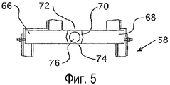
На фигуре 5 представлен вид сверху затвора согласно настоящему изобретению.5 is a top view of a shutter according to the present invention.
На фигуре 6 представлен вид спереди затвора согласно настоящему изобретению.6 is a front view of a shutter according to the present invention.
На фигуре 7 представлен вид сбоку затвора согласно настоящему изобретению.7 is a side view of a shutter according to the present invention.
На фигуре 8 представлен боковой изометрический вид с частичным разрезом еще одного варианта осуществления литейной формы согласно настоящему изобретению.The figure 8 presents a side isometric view in partial section of another embodiment of a mold according to the present invention.
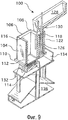
На фигуре 9 представлен боковой изометрический вид с разрезом еще одного альтернативного варианта осуществления литейной формы согласно настоящему изобретению.9 is a cross-sectional side elevational view of another alternative embodiment of the mold according to the present invention.
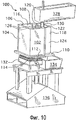
На фигуре 10 представлен боковой вид в изометрии литейной формы согласно фигуре 9.The figure 10 presents a side view in isometric of the mold according to figure 9.
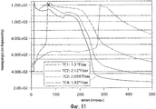
На фигуре 11 представлен график, демонстрирующий температуру литья во времени, в течение которого происходит процесс затвердевания, взятый в качестве примера.Figure 11 is a graph showing the casting temperature over time during which the solidification process, taken as an example, takes place.
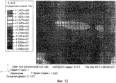
На фигуре 12 представлен график, демонстрирующий распределение напряжений по поперечному сечению слитка, изготовленного согласно настоящему изобретению.12 is a graph showing the stress distribution over the cross section of an ingot made according to the present invention.
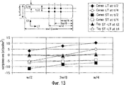
На фигуре 13 представлен график, демонстрирующий напряжение в различных местах внутри слитка, отлитого посредством использования известных способов.Figure 13 is a graph showing stresses at various places within an ingot cast by using known methods.
На фигуре 14 представлен изометрический вид с разрезом еще одного варианта осуществления литейной формы и переходной камеры согласно настоящему изобретению.Figure 14 is an isometric sectional view of yet another embodiment of a mold and a transition chamber according to the present invention.
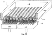
На фигуре 15 представлен передний изометрический вид с разрезом полости литейной формы согласно настоящему изобретению.The figure 15 presents a front isometric view with a cut cavity of the mold according to the present invention.
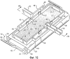
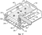
На фигуре 16 представлен изометрический вид сверху литейной формы согласно еще одному варианту осуществления настоящего изобретения, демонстрирующий перфорированную часть транспортера ниже литейной формы.Figure 16 is an isometric plan view of a mold according to another embodiment of the present invention, showing a perforated portion of the conveyor below the mold.
На фигуре 17 представлен изометрический вид сверху литейной формы, показанной на фигуре 16, с частичным сечением по линии 16-16 на фигуре 16.The figure 17 presents an isometric top view of the mold shown in figure 16, with a partial section along the line 16-16 in figure 16.
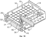
На фигуре 18 представлен изометрический вид сверху литейной формы, показанной на фигуре 16, при этом сетчатая часть транспортера находится ниже литейной формы.Figure 18 is an isometric top view of the mold shown in Figure 16, wherein the mesh portion of the conveyor is below the mold.
На фигуре 19А представлен вид в перспективе трехслойного слитка, для поверхностного листового продукта, имеющего сплав 2024, расположенный между двумя слоями сплава 1050.19A is a perspective view of a three-layer ingot for a surface sheet
На фигуре 19В представлен микроснимок прямоугольной ограниченной части, показанной на фигуре 19А, который демонстрирует поверхность раздела между сплавом 2024 и сплавом 1050.Figure 19B is a micrograph of a rectangular limited portion shown in Figure 19A, which shows the interface between
На фигуре 20А представлен вид в перспективе трехслойного слитка, для листового изделия в виде твердого припоя, содержащего сплав 3003, расположенный между двумя слоями сплава 4343.20A is a perspective view of a three-layer ingot for a sheet product in the form of a brazing
На фигуре 20В представлен микроснимок прямоугольной ограниченной части, показанной на фигуре 20А, который демонстрирует поверхность раздела между сплавом 3003 и сплавом 4343.Figure 20B is a micrograph of the rectangular limited portion shown in Figure 20A, which shows the interface between
На всех фигурах одинаковые элементы обозначены одинаковыми позициями.In all figures, the same elements are denoted by the same positions.
ПОДРОБНОЕ ОПИСАНИЕ ПРЕДПОЧТИТЕЛЬНЫХ ВАРИАНТОВ ОСУЩЕСТВЛЕНИЯ ИЗОБРЕТЕНИЯDETAILED DESCRIPTION OF THE PREFERRED EMBODIMENTS
В настоящем изобретении созданы устройство и способ однонаправленного затвердевания отливки, при этом также обеспечена контролируемая, равномерная скорость затвердевания.The present invention provides an apparatus and method for unidirectional solidification of a casting, while a controlled, uniform solidification rate is also provided.
Как показано на фигурах 1-4, литейная форма 10 включает в себя четыре стороны соответственно 12, 14, 16, 18 с образуемой внутри них литейной полостью 19. Предпочтительно, чтобы стороны 12, 14, 16, 18 были изолированы. Донная часть 20 может быть образована транспортером, имеющим сплошную часть 22 и сетчатую часть 24. Транспортер 20 выполнен непрерывным, оборачивающимся вокруг роликов соответственно 26, 28, 30, 32, так что либо сплошная часть 22, либо сетчатая часть 24 может быть избирательно расположена под сторонами 12, 14, 16, 18. Транспортер может быть изготовлен из любого жесткого материала, имеющего высокий коэффициент теплопроводности, причем примеры такого материала включают в себя медь, алюминий, нержавеющую сталь и Inconal. Следует заметить, что сетчатый участок 24 представляет собой участок, имеющий отверстия.As shown in figures 1-4, the
Камера 34 для подачи расплавленного металла, образуемая сторонами 36, 38, 40, сформирована вдоль стороны 12. Таким же образом, подобная камера 42 для подачи расплавленного металла образована сторонами 44, 46, 48 вдоль стороны 16. Некоторые варианты осуществления настоящего изобретения могут иметь только одну камеру для подачи расплавленного металла, а другие варианты могут иметь большое количество таких камер. Подающий желоб 50, 52 проходит от печи с расплавленным металлом (не показана, но хорошо известна в области литья) к месту непосредственно выше каждой из камер соответственно 34, 42, предназначенных для подачи расплавленного металла. Сливная труба 54 проходит от подающего желоба 50 к камере 34 для подачи расплавленного металла. Подобным же образом, сливная труба 56 проходит от подающего желоба 52 к камере 42 для подачи расплавленного металла.A molten
Сторона 12 включает в себя один или более затворы 58, 60, сконструированные таким образом, чтобы управлять потоком расплавленного металла из подающей камеры 34 к литейной полости 19. Подобным же образом, сторона 16 включает в себя затворы 62, 64, сконструированные таким образом, чтобы управлять потоком расплавленного металла из подающей камеры 42 к литейной полости 19. Затворы 58, 60, 62, 64 фактически идентичны и наилучшим образом представлены на фигурах 5-7. Затвор 58 включает в себя пару стенок 66, 68, образующих между собой фактически цилиндрический канал 70. Канал 70 включает в себя открытые стороны 72, 74 на противоположных сторонах стенок 66, 68. Цилиндрический затворный элемент 76 расположен внутри канала 70. Цилиндрический затворный элемент 76 фактически является сплошным и образует спиральную прорезь 78 вокруг своей периферии. Канал 70, цилиндрический затворный элемент 76 и спиральная прорезь 78 сконструированы таким образом, что будет обеспечена возможность течения расплавленного металла через часть спиральной прорези 78, которая прилегает непосредственно к одной из стенок 66, 68, при этом будет оказано сопротивление прохождению расплавленного металла через какую-либо другую часть затвора 58. Приводной механизм 80 функционально соединен с цилиндрическим затворным элементом 76 для управления вращением цилиндрического затворного элемента 76. Соответствующие приводные механизмы 80 хорошо известны квалифицированным специалистам в этой области и поэтому здесь весьма подробно не будут описаны. Приводной механизм 80 может, например, включать в себя электродвигатель, соединенный через передаточную систему с цилиндрическим затворным элементом 76, при этом электродвигателем управляют либо посредством ручного переключения, осуществляемого оператором, наблюдающим за процессом литья, либо посредством соответствующего микропроцессора.
Если возвратиться к фигурам 1-4, то согласно им внутри транспортера 20 расположен коллектор 82 для охладителя, при этом он сконструирован таким образом, чтобы распылять охладитель к донной поверхности 22, 24 литейной полости 19. Предпочтительно, коллектор 82 для охладителя сконструирован таким образом, чтобы подавать воздух, воду или их смесь в зависимости от желаемой скорости охлаждения.If we return to figures 1-4, then according to them inside the
При использовании транспортер 20 будет находиться в положении, представленном на фигурах 1-2, при этом сплошная часть 22 будет находиться непосредственно под полостью 19 литейной формы. Расплавленный металл будет введен из подающего желоба 50 через сливную трубу 54 в подающую камеру 34. У затворов 58, 60 их цилиндрические затворные элементы 76, будут повернуты таким образом, что самая нижняя часть спиральной прорези 78 будет прилегать к стенке 66 или стенке 68, обеспечивая при этом возможность прохождения расплавленного металла в полость 19 литейной формы посредством течения фактически по горизонтали на поверхности 22 транспортера. В то же время воздух будет распылен из коллектора 82 для охладителя снизу поверхности 22. Когда полость 19 литейной формы заполнена расплавленным металлом, цилиндрический затворный элемент 76 будет повернут таким образом, что все более и более поднимающиеся части спиральной прорези 78 будут прилегать к какой-либо из стенок 66, 68, так что когда уровень металла внутри литейной полости 19 будет поднят, часть спиральной прорези 78, через которую обеспечивают пропускание расплавленного металла, будет поднята на соответствующую величину, при этом поток расплавленного металла из камеры 34 к полости 19 литейной формы всегда будет горизонтальным и всегда поверх металла, который уже находится внутри полости 19. Горизонтальный поток металла к полости 19 литейной формы позволит расплавленному металлу соответствующим образом сформировать его уровень, гарантируя при этом фактически равномерную толщину расплавленного металла внутри полости 19 литейной формы.In use, the
Когда в полость 19 литейной формы добавляют дополнительный металл, скорость охлаждения металла, находящегося внутри литейной полости 19, будет замедлена. Для сохранения фактически постоянной скорости охлаждения смесь охладителя из коллектора 82 будет изменена с воздуха на воздушно-водяную смесь, содержащую увеличенное количество воды, а в конечном счете она будет полностью изменена на воду. Кроме того, когда металл в донной части литейной формы 19 затвердевает, транспортер 20 будет продвинут таким образом, что донная часть литейной формы 10 будет образована сеткой 24 вместо сплошной части 22, обеспечивая при этом непосредственный контакт охладителя с затвердевшим металлом, как показано на фигурах 3-4. Далее, скорость подачи металла, добавляемого к литейной полости 19, может быть замедлена посредством управления вращением цилиндрических затворных элементов 76 затворов 58, 60 и/или скоростью введения металла в подающую камеру 34 из подающего желоба 50. Обычно скорость охлаждения будет оставаться примерно между 0,5°F/с и 3°F/с, при этом скорость охлаждения обычно понижают примерно от 3°F/с в начале литья до 0,5°F/с при завершении литья. Подобным же образом, скорость, с которой расплавленный металл вводят в полость 19 литейной формы, по ходу выполнения литья будет уменьшена с начальной величины, примерно составляющей 4 дюйма/мин, до конечной величины 0,5 дюйма/мин.When additional metal is added to the
Если необходимо, в подающую камеру 42 из подающего желоба 52 через сливную трубу 56 может быть введен второй сплав. Этот второй сплав может быть использован для плакирования первого сплава. Например, плакирование может быть в виде слоя, стойкого к коррозии. Один из примеров плакирования может быть образован посредством первоначального введения сплава из первой камеры 42 через затворы 62, 64 в литейную полость 19 посредством вращения цилиндрических затворных элементов 76 затворов 62, 64, так что металл течет из донной части спирального канала 78 внутри этих затворов в литейную камеру 19, после чего затворы 62, 64 закрывают. Цилиндрические затворные элементы 76 затворов 58, 60 затем поворачивают для возможности прохождения потока расплавленного металла из подающей камеры 34 в литейную полость 19 у все более и более приподнимающихся частей спиральной прорези 78, пока литейная полость 19 не будет заполнена почти на всем пути к верхней части, и в этот момент затворы 58, 60 закрывают. После этого цилиндрические затворные элементы 76 затворов 62, 64 поворачивают для возможности прохождения потока металла из подающей камеры 42 в полость 19 литейной формы у самой высокой части прорезей 78 внутри цилиндрических затворных элементов 76 затворов 62, 64, обеспечивая тем самым возможность течения этого расплавленного металла к верхней части металла, уже находящегося в литейной форме. Полученная основа, образуемая из сплава внутри подающей камеры 34, будет иметь плакирование на верхней части и донной части, выполненное из сплава из подающей камеры 42.If necessary, a second alloy may be introduced into the
Для обеспечения соответствующего сцепления на границе раздела каких-либо двух последовательных слоев должен быть выполнен указанный далее процесс. Температура поверхности базового слоя после введения нового последующего слоя, который имеет состав, отличающийся от состава базового слоя, должна быть меньше, чем температура ликвидуса (Tliq), и больше, чем температура эвтектики (Teut)-50°С, где Tliq температура ликвидуса базового слоя, а Teut температура эвтектики базового слоя. Этот процесс не ограничен только плакированием. Он обеспечивает возможность последовательного литья большого количества сплавов для создания изделия в виде слитка с большим количеством слоев.To ensure proper adhesion at the interface of any two consecutive layers, the following process should be performed. The surface temperature of the base layer after the introduction of a new subsequent layer, which has a composition different from the composition of the base layer, should be less than the liquidus temperature (T liq ) and more than the eutectic temperature (T eut ) -50 ° С, where T liq the liquidus temperature of the base layer, and T eut the eutectic temperature of the base layer. This process is not limited to cladding only. It provides the possibility of sequential casting of a large number of alloys to create a product in the form of an ingot with a large number of layers.
Еще один вариант выполнения литейной формы 84 представлен на фигуре 8. Литейная форма 84 имеет четыре стороны, из которых представлены три стороны 86, 88, 90. Стороны 86, 88, 90 и четвертая фактически идентичная, но не показанная сторона, могут быть изолированы. Донная часть литейной формы 84 образована посредством ткани 92, которая может быть изготовлена из того же самого материала, что и донный транспортер 20 предыдущего варианта 10. Донная основа 94 сконструирована таким образом, чтобы она перемещалась между верхним положением, представленным на фигуре 8 сплошными линиями, в котором она удерживает ткань 92, и нижним положением, представленным на фигуре 8 пунктирными линиями, в котором ее удаляют от ткани 92 на достаточное расстояние, так чтобы между ними могли быть расположены распылительные коробки 96, 98. Распылительные коробки 96, 98 сконструированы таким образом, чтобы их можно было перемещать из положения ниже ткани 92 в положение, в котором будет обеспечена возможность перемещения основы 94 между верхним и нижним положением. При этом распылительные коробки 96, 98 будут подавать воздух, воду или их смесь, либо, возможно, другие охладители к донной части основы 94, либо к донной части ткани 92 в зависимости от того, находится ли основа 94 выше или ниже распылительных коробок 96, 98.Another embodiment of the
При использовании основа 94 будет находиться в верхнем положении, удерживая ткань 92. Расплавленный металл будет введен в литейную форму 84, при этом к донной части основы 94 будет подан воздух, обеспечивая охлаждение. Когда литейная форма 84 заполнена расплавленным металлом и расплавленный металл на донной части затвердевает, распылительные коробки 96, 98 будут быстро отведены из их положения под основой 94, обеспечивая при этом удаление основы 94 из ее положения под тканью 92. Затем распылительные коробки 96, 98 будут помещены назад под ткань 92, так что они могут подавать воздух, смесь воздуха и воды или воду к донной части ткани 92, с увеличением количества воды, подаваемой к донной части ткани 92, в ходе выполнения литья.In use, the
На фигурах 9 и 10 представлен еще один вариант осуществления литейной формы 100, которая может быть использована для выполнения способа согласно настоящему изобретению. Литейная форма 100 включает в себя стенки 102, 104, 106 и 108, которые могут быть изолированы. Донная часть включает в себя неподвижную донную плиту 110, образующую отверстие ниже стенок 102, 104, 106, 108, в которое может быть вставлена удаляемая донная плита 112. Удаляемая донная плита 112 может быть изготовлена из такого материала как медь. Неподвижная донная плита 110 в некоторых вариантах может образовывать прорезь 114, сконструированную таким образом, чтобы в нее заходили края удаляемой донной плиты 112, тем самым поддерживая удаляемую донную плиту 112. Стенки 102, 104, 106, 108 и удаляемая донная плита 112 образуют полость 116 литейной формы.Figures 9 and 10 show another embodiment of the
Камера 118 для подачи расплавленного металла образована стенками 120, 122 и 124 совместно со стенкой 108 и неподвижной донной плитой 110. В стенке 108 образован затвор 126, причем в представленных примерах он сформирован посредством пары прорезей, образуемых внутри стенки 108. Подающий желоб 128 проходит от печи с расплавленным металлом к месту непосредственно над камерой 118 для подачи расплавленного металла. Сливная труба 130 проходит от подающего желоба 128 к камере 118.The
Коллектор 132 для охладителя расположен ниже удаляемой донной плиты 112. Коллектор 132 предпочтительно сконструирован таким образом, чтобы он избирательно распылял воздух, воду или смесь воздуха и воды к удаляемой донной плите 112. Представленный вариант дополнительно включает в себя отстойный бассейн 134, расположенный ниже камеры 118. Всю форму 100 удерживают на основании 136.The
При использовании удаляемая донная плита 112 будет находиться внутри прорези 114. Расплавленный металл будет введен из подающего желоба 128 в подающую камеру 118, пока уровень расплавленного металла внутри подающей камеры 118 не достигнет донной части прорезей 126. Прорези 126 в сочетании с соответствующим образом выбранной скоростью подачи к подающей камере 118 будет гарантировать, что скорость подачи расплавленного металла к полости 116 литейной формы будет контролируемой. Когда уровень расплавленного металла внутри полости 116 поднимается, скорость подачи расплавленного металла в подающую камеру 118 может быть отрегулирована таким образом, что расплавленный металл будет вытекать из прорези 126 непосредственно на верхнюю часть расплавленного металла внутри полости 116 литейной формы, обеспечивая при этом фактически горизонтальный поток расплавленного металла к литейной полости 116. Охладитель будет распылен к удаляемой донной плите 112 посредством коллектора 132, начиная с воздуха, с последующим переключением на смесь воздуха и воды и, наконец, на воду. Когда расплавленный металл в донной части полости 116 литейной формы затвердевает, удаляемая донная плита 112 может быть удалена, обеспечивая при этом непосредственный контакт охладителя с нижней стороной слитка внутри полости 116 литейной формы.In use, the
В одном из примеров процесса литья согласно настоящему изобретению алюминиевый сплав 7085 был отлит в виде слитка с размерами 9 дюймов×13 дюймов×7 дюймов, используя литейную форму 100, которая показана на фигурах 9-10. Начальная температура металла составляла 1280°F. Удаляемая донная плита 112 была изготовлена в виде плиты из нержавеющей стали толщиной 0,5 дюйма. Вдоль осевой линии слитка на расстоянии 0,25 дюйма, 0,75 дюйма, 2 дюйма и 4 дюйма от удаляемой донной плиты 112 были расположены термопары. Полость 116 литейной формы первоначально была заполнена со скоростью порядка 2 дюймов за каждые 30 секунд, при этом по ходу выполнения литья происходило замедление скорости заполнения. Начальная скорость потока воды составляла 0,25 галлона в минуту, причем вода находилась в виде смеси, сочетающей воздух и воду. Удаляемая донная плита 112 была удалена, когда показания термопары, расположенной на расстоянии 0,25 дюйма от удаляемой донной плиты 112, составляли 1080°F. В этот момент скорость потока воды была увеличена до 1 галлона в минуту.In one example of a casting process according to the present invention, the aluminum alloy 7085 was cast in the form of an ingot with dimensions of 9 inches × 13 inches × 7 inches using the
На фигуре 11 представлена скорость охлаждения у каждой из четырех термопар. Как можно видеть на этой фигуре, скорость охлаждения находится в диапазоне от 1,5 до 2,12°F/с, при этом скорость охлаждения фактически равномерна.Figure 11 shows the cooling rate of each of the four thermocouples. As can be seen in this figure, the cooling rate is in the range from 1.5 to 2.12 ° F / s, while the cooling rate is practically uniform.
На фигуре 12 представлен график, демонстрирующий остаточные напряжения по поперечному сечению слитка. Эти данные были получены посредством резания слитка пополам в направлении по размеру, составляющему 9 дюймов, и последующего измерения получаемой деформации поверхности в виде напряжений внутри релаксированного материала. За исключением одного напряжения растяжения в нижнем левостороннем углу согласно фигуре 12 и одного напряжения сжатия в нижней центральной части согласно фигуре 12, величина напряжений по слитку составила от 0,6 до 3 кг/дюйм2. Повышенное напряжение сжатия в центре донной части слитка вызывает незначительное беспокойство, поскольку напряжение сжатия обычно не приводит к растрескиванию. Высокие напряжения сжатия в этом месте и высокие напряжения растяжения в нижнем левом углу, вероятно, являются результатом первоначального столкновения расплавленного металла с основой в этих местах, что приводит к формированию приваренных корольков и, возможно, других дефектов. Наибольшее напряжение растяжения составило +6е+02 фунтов/дюйм2.12 is a graph showing residual stresses over the cross section of an ingot. These data were obtained by cutting the ingot in half in the direction of 9 inches in size and then measuring the resulting surface deformation in the form of stresses inside the relaxed material. With the exception of one tensile stress in the lower left-hand corner according to Figure 12 and one compression stress in the lower central part according to Figure 12, the value of the stress on the ingot ranged from 0.6 to 3 kg / inch 2 . The increased compression stress in the center of the bottom of the ingot is of little concern, since the compression stress usually does not lead to cracking. The high compressive stresses at this location and the high tensile stresses in the lower left corner are probably the result of the initial collision of the molten metal with the base at these locations, which leads to the formation of welded kings and possibly other defects. The highest tensile stress was + 6e 02 lb / in2.
На фигуре 13 представлены остаточные напряжения по поперечному сечению размером 4 дюйма на 13 дюймов отлитого под давлением слитка из алюминиевого сплава 7085. Как показано на фигуре, остаточные напряжения, получаемые в отливке, выполняемой в настоящее время посредством литья под давлением, могут достигать 10 ksi. Однако напряжения в этом слитке, вероятно, были даже выше, поскольку слиток уже имел продольную трещину, когда был произведен замер напряжений, которая ослабила эти напряжения. Из используемых на фигуре обозначений сигма относится к напряжениям растяжения или сжатия, тау относится к напряжению сдвига, LT относится к направлению, фактически параллельному длине, а ST относится к направлению, фактически параллельному толщине.Figure 13 shows the residual stresses in a cross section of 4 inches by 13 inches of a die-cast ingot of aluminum alloy 7085. As shown in the figure, the residual stresses obtained in the casting currently performed by injection molding can reach 10 ksi. However, the stresses in this ingot were probably even higher, since the ingot already had a longitudinal crack when stress measurements were made, which weakened these stresses. Of the notation used in the figure, sigma refers to tensile or compressive stresses, tau refers to shear stress, LT refers to a direction that is actually parallel to the length, and ST refers to a direction that is actually parallel to the thickness.
Воздействие охладителя на донную часть литейной формы совместно с обеспечиваемой в некоторых предпочтительных вариантах изоляцией на сторонах 12, 14, 16, 18 приводит к направленному затвердеванию отливки от донной части к верхней части полости 19 литейной формы. Предпочтительно, чтобы скорость введения расплавленного металла в полость 19 литейной формы в сочетании со скоростью охлаждения была регулируема как примерно от 0,1 дюйма (2,54 мм) до 1 дюйма (25,4 мм) расплавленного металла внутри полости 19 за какое-либо заданное время. В некоторых вариантах мягкая зона между расплавленным металлом и затвердевшим металлом также может быть сохранена с фактически равномерной толщиной. В результате этого направленного затвердевании, равномерной температуры, а также тонких участков расплавленного металла и квазиравновесной двухфазной зоны макросегрегация будет значительно уменьшена или исключена.The effect of the cooler on the bottom of the mold, together with the insulation provided on some sides, on the
На фигуре 14 представлена еще одна литейная форма в сборе 138. Литейная форма в сборе 138 включает в себя стороны 140, 142, 144, при этом четвертая сторона, которая на фигуре с вырезом не представлена, противоположна стороне 142. Все четыре стенки 140, 142, 144 и не представленная стенка могут быть изолированы, при этом предпочтительным изоляционным материалом является графит. Литейная форма 138 дополнительно включает в себя донную часть 146, которая предпочтительно содержит большое количество отверстий 148 (наилучшим образом показанных на фигуре 15), диаметр которых достаточно велик для возможности прохождения обычных охладителей, таких как воздух или вода, но он также достаточно мал, чтобы оказывать сопротивление прохождению через них расплавленного металла. Предпочтительный диаметр отверстий 148 составляет примерно от 1/64 дюйма до одного дюйма. Полость 150 формы образована стенками 140, 142, 144, четвертой стенкой и донной частью 146. В стенке 144 образована прорезь, при этом край 152 прорези виден на фигуре 14.Figure 14 shows another
Камера 154 для подачи расплавленного металла образована стенками 156, 158, 160, четвертой стенкой, которая не показана, и днищем 162. Подающий желоб 164 проходит от печи с расплавленным металлом к месту непосредственно над камерой 154 для подачи расплавленного металла. От подающего желоба 164 к камере 154 проходит сливная труба 166.The
Затвор 168 имеет Н-образную конструкцию, содержащую пару вертикальных элементов 170, 172 для закрывания прорези, соединенных посредством горизонтального элемента 174 с образованием проходящего через него канала 176. Элемент 170 для закрывания прорези сконструирован таким образом, чтобы фактически закрывать прорезь в стенке 144 полости 150 литейной формы, в то время как закрывающий элемент 172 сконструирован так, чтобы фактически закрывать прорезь, образуемую внутри стенки 156 камеры 154 для подачи расплавленного металла. Затвор 168 сконструирован так, чтобы скользить между нижним положением, в котором канал 176 расположен вблизи от донной части 146 полости 150 литейной формы, и верхним положением, соответствующим верхней части литейной полости 150. Элементы 170, 172 для закрывания прорези сконструированы так, чтобы оказывать сопротивление потоку расплавленного металла через прорези, образуемые в стенках 144, 156 в любом месте, за исключением канала 176, независимо от положения затвора 168.The
Ниже донной части 146 расположен коллектор 178 для охладителя. Коллектор 178 предпочтительно сконструирован так, чтобы избирательно распылять воздух, воду или смесь воздуха и воды к донной части 146.Below the bottom 146 is a
Над полостью 150 литейной формы расположен лазерный датчик 180, при этом он предпочтительно сконструирован таким образом, чтобы контролировать уровень расплавленного металла внутри полости 150.A
При использовании расплавленный металл будет введен через подающий желоб 164 в подающую камеру 154. Далее расплавленный металл может течь по каналу 176 в полость 150 литейной формы. Когда уровень расплавленного металла внутри полости 150 литейной формы повышается, затвор 168 будет подниматься, так что расплавленный металл всегда течет по горизонтали от подающей камеры 154 непосредственно на верхнюю часть расплавленного металла, уже находящегося в полости 150 литейной формы. Скорость подачи расплавленного металла к полости 150 по ходу выполнения охлаждения может быть замедлена, чтобы управлять скоростью охлаждения. Соответственно, охладитель, текущий из коллектора 178, по ходу выполнения литья будет изменен с воздуха на смесь воздуха и воды, и полностью на воду для управления скоростью охлаждения расплавленного металла внутри полости 150 литейной камеры. Поскольку охладитель может непосредственно сталкиваться с металлом внутри полости 150, необязательно удалять донную часть 146 в течение процесса литья.In use, molten metal will be introduced through
На фигуре 16 представлен вид в изометрии сверху литейной формы согласно еще одному варианту осуществления настоящего изобретения, демонстрирующий перфорированную часть транспортера ниже литейной формы. Все находящиеся на фигуре 16 элементы, аналогичные элементам на фигуре 1 и обозначены теми же позициями. Литейная форма 10 включает в себя четыре стороны соответственно 12, 14, 16, 18 с образованием ими литейной полости 19. Стороны 12, 14, 16, 18 предпочтительно изолированы. Донная часть 20 может быть образована посредством транспортера, имеющего перфорированную часть 22 и сетчатую часть 24. Транспортер 20 выполнен непрерывным, оборачивающимся вокруг роликов соответственно 26, 28, 30, 32, так что либо перфорированная часть 22, либо сетчатая часть 24 может быть избирательно расположена под сторонами 12, 14, 16, 18. Транспортер может быть изготовлен из любого жесткого материала, обладающего высокой теплопроводностью, включая, например, медь, алюминий, нержавеющую сталь и Inconal.16 is a top isometric view of a mold according to yet another embodiment of the present invention, showing a perforated portion of the conveyor below the mold. All elements in figure 16 are similar to those in figure 1 and are denoted by the same positions. The
На фигуре 17 частично в сечении по линии 16-16, указанной на фигуре 16, представлен изотермический вид сверху литейной формы, показанной на фигуре 16.The figure 17 is partially in section along the line 16-16 indicated in figure 16, is an isothermal top view of the mold shown in figure 16.
На фигуре 18 частично в сечении представлен изометрический вид сверху литейной формы, показанной на фигуре 16, при этом сетчатая часть транспортера находится ниже литейной формы.Figure 18 is partially a sectional view showing a top view of the mold shown in Figure 16, wherein the mesh portion of the conveyor is below the mold.
Фигуры 16, 17 и 18 подобны фигурам 1, 2 и 4. Основное различие между двумя группами фигур заключается в том, что фигуры 1, 2 и 4 соответственно показывают сплошную и сетчатую часть транспортера ниже литейной формы, в то время как фигуры 16, 17 и 18 соответственно показывают перфорированную и сетчатую часть транспортера ниже литейной формы.Figures 16, 17 and 18 are similar to Figures 1, 2 and 4. The main difference between the two groups of figures is that Figures 1, 2 and 4 respectively show the solid and mesh part of the conveyor below the mold, while Figures 16, 17 and 18 respectively show the perforated and mesh portion of the conveyor below the mold.
На фигуре 19А представлен многослойный, состоящий из трех слоев слиток для поверхностного листового изделия, содержащий сплав 2024, расположенный между двумя слоями сплава 1050. В данном случае сплав 2024 имеет температуру ликвидуса 1180°F и температуру эвтектики порядка 935°F, а сплав 1050 имеет температуру ликвидуса 1198°F и температуру эвтектики порядка 1189°F. В этом примере на слой литья толщиной 0,75 дюйма первого плакировочного слоя сплава 1050 был разлит слой внутреннего сплава 2024 толщиной 3,5 дюйма с контролируемой скоростью порядка 0,7 дюйма в минуту, гарантируя, что температура поверхности раздела будет повышена до значения, находящегося между 1148°F и 1189°F. После литья материала внутренней части был разлит второй плакировочный слой сплава толщиной 0,75 дюйма, гарантируя, что температура поверхности раздела будет повышена до значения, находящегося между 885°F и 1180°F.19A depicts a multi-layer, three-layer ingot for a surface sheet
На фигуре 19В представлена микрофотография, демонстрирующая поверхность раздела между сплавом 2024 и сплавом 1050 прямоугольного участка многослойного, состоящего из трех слоев слитка согласно фигуре 19А. Показано, что поверхность раздела между сплавом 2024 и сплавом 1050 имеет оптимальное сцепление.Figure 19B is a photomicrograph showing the interface between the
На фигуре 20А показан многослойный, состоящий из трех слоев слиток для листового изделия, представляющего собой припой, имеющего сплав 3003, расположенный между двумя слоями сплава 4343. В данном случае сплав 3003 имеет температуру ликвидуса 1211°F и температуру эвтектики 1173°F, а сплав 4343 имеет температуру ликвидуса 1133°F и температуру эвтектики порядка 1068°F. В этом примере на слой литья толщиной 0,75 дюйма первого плакировочного слоя из сплава 4343 был разлит слой внутреннего сплава 3003 толщиной 5,5 дюйма с контролируемой скоростью порядка 0,7 дюйма в минуту, гарантируя, что температура поверхности раздела будет повышена до значения, находящегося между 1018°F и 1083°F. После литья материала внутренней части был разлит второй плакировочный слой сплава толщиной 0,75 дюйма, гарантируя, что температура поверхности раздела будет повышена до значения, находящегося между 1123°F и 1211°F.20A shows a multilayer ingot consisting of three layers of an ingot for a sheet product, which is a
На фигуре 20В представлена микрофотография, демонстрирующая поверхность раздела между сплавом 3003 и сплавом 4343 прямоугольного участка многослойного, состоящего из трех слоев слитка согласно фигуре 20А. Показано, что поверхность раздела между сплавом 3003 и сплавом 4343 имеет оптимальное сцепление.Figure 20B is a photomicrograph showing the interface between
В настоящем изобретении многослойный продукт в виде слитка не ограничен двумя или тремя слоями из сплавов. Многослойный продукт в виде слитка может иметь более трех слоев из сплавов.In the present invention, the multilayer product in the form of an ingot is not limited to two or three layers of alloys. The multilayer product in the form of an ingot may have more than three layers of alloys.
Таким образом, в настоящем изобретении созданы устройство и способ для получения слитков с направленным затвердеванием и с охлаждением таких слитков с контролируемой, относительно постоянной скоростью охлаждения. Изобретение обеспечивает возможность литья слитков, не содержащих трещин, без необходимости снятия напряжений. Способ снижает или исключает макросегрегацию, приводя к однородной микроструктуре по слитку. Способ, кроме того, позволяет создать слитки, имеющие фактически равномерную толщину, которые могут быть тоньше, чем слитки, отлитые посредством использования других способов. Большая площадь поверхности, находящаяся в контакте с охладителем, приводит к относительно быстрому охлаждению, позволяя обеспечить более высокую производительность.Thus, the present invention provides a device and method for producing ingots with directional solidification and cooling of such ingots with a controlled, relatively constant cooling rate. The invention provides the possibility of casting ingots without cracks, without the need for stress relief. The method reduces or eliminates macrosegregation, leading to a homogeneous ingot microstructure. The method, in addition, allows you to create ingots having virtually uniform thickness, which can be thinner than ingots cast using other methods. The large surface area in contact with the cooler leads to relatively quick cooling, allowing for higher performance.
Хотя подробно описаны определенные варианты осуществления изобретения, квалифицированным специалистам в этой области будет понятно, что в свете общих идей, раскрытых в данном документе, могут быть разработаны различные модификации и альтернативные варианты приведенных деталей. Соответственно, следует полагать, что конкретные раскрытые компоновки носят лишь иллюстративный характер и не ограничивают объем изобретения, всю полноту которого определяют пункты формулы изобретения и какие-либо или все их эквиваленты.Although certain embodiments of the invention have been described in detail, those skilled in the art will understand that, in light of the general ideas disclosed herein, various modifications and alternatives to the details may be devised. Accordingly, it should be assumed that the specific disclosed arrangements are merely illustrative and do not limit the scope of the invention, the entirety of which is defined by the claims and any or all of their equivalents.
Claims (35)
Applications Claiming Priority (4)
| Application Number | Priority Date | Filing Date | Title |
|---|---|---|---|
| US11/179,835 | 2005-07-12 | ||
| US11/179,835 US7264038B2 (en) | 2005-07-12 | 2005-07-12 | Method of unidirectional solidification of castings and associated apparatus |
| US11/484,276 | 2006-07-11 | ||
| US11/484,276 US7377304B2 (en) | 2005-07-12 | 2006-07-11 | Method of unidirectional solidification of castings and associated apparatus |
Related Parent Applications (1)
| Application Number | Title | Priority Date | Filing Date |
|---|---|---|---|
| RU2008105040/02A Division RU2413591C2 (en) | 2005-07-12 | 2006-07-12 | Method of unidirectional curing of billets and device to this end |
Publications (2)
| Publication Number | Publication Date |
|---|---|
| RU2010149724A RU2010149724A (en) | 2012-06-10 |
| RU2569857C2 true RU2569857C2 (en) | 2015-11-27 |
Family
ID=37307316
Family Applications (3)
| Application Number | Title | Priority Date | Filing Date |
|---|---|---|---|
| RU2008105040/02A RU2413591C2 (en) | 2005-07-12 | 2006-07-12 | Method of unidirectional curing of billets and device to this end |
| RU2010149724/02A RU2569857C2 (en) | 2005-07-12 | 2006-07-12 | Method of unidirectional solidification of castings and related to this device |
| RU2015145103A RU2015145103A (en) | 2005-07-12 | 2015-10-20 | METHOD FOR ONE-DIRECTION CURING OF CASTINGS AND RELATED DEVICE |
Family Applications Before (1)
| Application Number | Title | Priority Date | Filing Date |
|---|---|---|---|
| RU2008105040/02A RU2413591C2 (en) | 2005-07-12 | 2006-07-12 | Method of unidirectional curing of billets and device to this end |
Family Applications After (1)
| Application Number | Title | Priority Date | Filing Date |
|---|---|---|---|
| RU2015145103A RU2015145103A (en) | 2005-07-12 | 2015-10-20 | METHOD FOR ONE-DIRECTION CURING OF CASTINGS AND RELATED DEVICE |
Country Status (10)
| Country | Link |
|---|---|
| US (2) | US7377304B2 (en) |
| EP (3) | EP2295167A1 (en) |
| JP (2) | JP2009501633A (en) |
| KR (1) | KR101367539B1 (en) |
| CN (1) | CN101780529B (en) |
| AU (1) | AU2006267086B2 (en) |
| BR (1) | BRPI0613728B1 (en) |
| CA (2) | CA2614753C (en) |
| RU (3) | RU2413591C2 (en) |
| WO (1) | WO2007009060A2 (en) |
Cited By (1)
| Publication number | Priority date | Publication date | Assignee | Title |
|---|---|---|---|---|
| RU2782365C1 (en) * | 2022-06-29 | 2022-10-26 | Федеральное государственное бюджетное образовательное учреждение высшего образования "Комсомольский-на-Амуре государственный университет" (ФГБОУ ВО "КнАГУ") | Method for manufacturing a hollow cast metal billet |
Families Citing this family (14)
| Publication number | Priority date | Publication date | Assignee | Title |
|---|---|---|---|---|
| US7264038B2 (en) * | 2005-07-12 | 2007-09-04 | Alcoa Inc. | Method of unidirectional solidification of castings and associated apparatus |
| US7377304B2 (en) * | 2005-07-12 | 2008-05-27 | Alcoa Inc. | Method of unidirectional solidification of castings and associated apparatus |
| JP4748426B2 (en) * | 2008-03-26 | 2011-08-17 | 独立行政法人科学技術振興機構 | Magnesium alloy mold and magnesium alloy casting method |
| US8448690B1 (en) * | 2008-05-21 | 2013-05-28 | Alcoa Inc. | Method for producing ingot with variable composition using planar solidification |
| US8534344B2 (en) * | 2009-03-31 | 2013-09-17 | Alcoa Inc. | System and method of producing multi-layered alloy products |
| CN102458716A (en) * | 2009-05-21 | 2012-05-16 | 美铝公司 | Method of producing ingot with variable composition using planar solidification |
| US20100304175A1 (en) * | 2009-05-29 | 2010-12-02 | Alcoa Inc. | High strength multi-layer brazing sheet structures with good controlled atmosphere brazing (cab) brazeability |
| US20110252956A1 (en) * | 2010-03-17 | 2011-10-20 | Alcoa Inc. | Armor with variable composition having metallurgically bonded layers |
| MX352255B (en) | 2010-09-08 | 2017-11-16 | Alcoa Inc Star | Improved 6xxx aluminum alloys, and methods for producing the same. |
| JP5669610B2 (en) * | 2011-02-15 | 2015-02-12 | 株式会社アステア | Direct current heating method |
| WO2013172910A2 (en) | 2012-03-07 | 2013-11-21 | Alcoa Inc. | Improved 2xxx aluminum alloys, and methods for producing the same |
| US9587298B2 (en) | 2013-02-19 | 2017-03-07 | Arconic Inc. | Heat treatable aluminum alloys having magnesium and zinc and methods for producing the same |
| RU2573283C1 (en) * | 2015-06-11 | 2016-01-20 | Цоло Вълков Рашев | Method of producing of metallurgical blanks, shaped castings, and device for its implementation |
| CN113770338A (en) * | 2021-08-27 | 2021-12-10 | 常州机电职业技术学院 | Metal matrix composite material forming system and forming method |
Citations (2)
| Publication number | Priority date | Publication date | Assignee | Title |
|---|---|---|---|---|
| SU384613A1 (en) * | 1970-01-31 | 1973-05-29 | Днепропетровский ордена Ленина металлургический завод имени Г. И. Петровского | |
| US20050011630A1 (en) * | 2003-06-24 | 2005-01-20 | Anderson Mark Douglas | Method for casting composite ingot |
Family Cites Families (55)
| Publication number | Priority date | Publication date | Assignee | Title |
|---|---|---|---|---|
| GB191308490A (en) * | 1913-04-10 | 1914-06-10 | Franz Melaun | A Process for Casting Ingots or other Castings. |
| US2301902A (en) * | 1938-07-01 | 1942-11-10 | Joseph M Merle | Method and apparatus for producing bimetallic products |
| US2244367A (en) * | 1939-06-10 | 1941-06-03 | Kinkead Robert Emerson | Making composite metal articles |
| US3206808A (en) * | 1962-08-14 | 1965-09-21 | Reynolds Metals Co | Composite-ingot casting system |
| US3752212A (en) * | 1970-07-20 | 1973-08-14 | Thompson E Manuf Co | Method of forming castings of different metals |
| JPS5832543B2 (en) | 1975-02-03 | 1983-07-13 | キヤノン株式会社 | recording device |
| DE2728048C2 (en) | 1977-06-22 | 1979-05-23 | Mahle Gmbh, 7000 Stuttgart | Process for the production of a molded part |
| JPS5677049A (en) * | 1979-11-27 | 1981-06-25 | Sumitomo Metal Ind Ltd | Production of longitudinally short steel ingot comprising plural layer dissimilar metals |
| GB2096503A (en) * | 1981-04-13 | 1982-10-20 | Rolls Royce | Mould assembly for producing multiple castings |
| JPS5832543A (en) * | 1981-08-21 | 1983-02-25 | Sumitomo Metal Ind Ltd | Manufacture and device for clad ingot |
| US4585047A (en) | 1984-02-01 | 1986-04-29 | Toyota Jidosha Kabushiki Kaisha | Apparatus for cooling molten metal in a mold |
| US4567936A (en) * | 1984-08-20 | 1986-02-04 | Kaiser Aluminum & Chemical Corporation | Composite ingot casting |
| JPS61169138A (en) * | 1985-01-23 | 1986-07-30 | Hitachi Ltd | Molding board for unidirectionally solidified steel ingot |
| JPS6349357A (en) * | 1986-08-19 | 1988-03-02 | Mitsubishi Heavy Ind Ltd | Centrifugal casting tube having two layers and casting method thereof |
| JPS6466061A (en) * | 1987-09-07 | 1989-03-13 | Nippon Steel Corp | Production of ingot having double layers |
| JPH01113164A (en) * | 1987-10-28 | 1989-05-01 | Daido Steel Co Ltd | Method and apparatus for producting unidirectionally solidified ingot |
| US5020583A (en) | 1988-11-10 | 1991-06-04 | Lanxide Technology Company, Lp | Directional solidification of metal matrix composites |
| US4969502A (en) | 1989-05-11 | 1990-11-13 | Cominco Ltd. | Method and apparatus for the casting of metals |
| JPH0688106B2 (en) | 1990-02-19 | 1994-11-09 | 株式会社オー・シー・シー | Horizontal continuous casting method for strip-shaped metal ingot and its equipment |
| US5476725A (en) * | 1991-03-18 | 1995-12-19 | Aluminum Company Of America | Clad metallurgical products and methods of manufacture |
| DE4304622C2 (en) | 1993-02-16 | 1996-09-19 | Bruehl Aluminiumtechnik | Process for filling a mold |
| US6495269B1 (en) * | 1996-12-03 | 2002-12-17 | Corus Aluminium Walzprodukte Gmbh | Multilayer metal composite products obtained by compound strand casting |
| JP2002079354A (en) | 2000-09-01 | 2002-03-19 | Showa Denko Kk | Mold for casting metal, method for casting metal and cast block |
| JP2002103024A (en) | 2000-09-22 | 2002-04-09 | Showa Denko Kk | Casting apparatus |
| EP1315587B1 (en) * | 2000-09-01 | 2007-10-17 | Showa Denko K.K. | Apparatus and method for casting metal |
| CA2439696C (en) * | 2001-03-12 | 2011-07-19 | Alcan International Limited | Method and apparatus for texturing a metal sheet or strip |
| JP3849092B2 (en) * | 2001-03-13 | 2006-11-22 | 古河スカイ株式会社 | Method for producing aluminum alloy clad material |
| US6902828B2 (en) * | 2001-04-09 | 2005-06-07 | Alcoa Inc. | Bright products obtained by continuous casting |
| GB2379669B (en) * | 2001-09-12 | 2005-02-16 | Alcan Int Ltd | Al alloy for lithographic sheet |
| US6705384B2 (en) * | 2001-10-23 | 2004-03-16 | Alcoa Inc. | Simultaneous multi-alloy casting |
| JP2003145249A (en) * | 2001-11-13 | 2003-05-20 | Mitsubishi Materials Corp | Casting mold for manufacturing ingot having minute unidirectionally solidified columnar crystal structure |
| FR2839518B1 (en) * | 2002-05-13 | 2004-06-25 | Pechiney Rhenalu | LIQUID METAL ONLINE PROCESSING DEVICE |
| ES2297500T3 (en) * | 2003-10-03 | 2008-05-01 | Novelis Inc. | COLOR BELT SURFACE TEXTURATION OF CONTINUOUS COLADA MACHINES. |
| ES2328698T3 (en) * | 2003-10-03 | 2009-11-17 | Novelis Inc. | COLADA IN TAPE OF NON-FERROUS AND LIGHT METALS AND EQUIPMENT FOR THE SAME |
| JP4340865B2 (en) * | 2003-11-13 | 2009-10-07 | トヨタ自動車株式会社 | Melting ingot, melting method and alloy casting |
| EP1533394A1 (en) * | 2003-11-20 | 2005-05-25 | Alcan Technology & Management Ltd. | Car body component |
| US20050127549A1 (en) * | 2003-12-11 | 2005-06-16 | Bischoff Todd F. | Method for suppressing reaction of molten metals with refractory materials |
| US7569525B2 (en) * | 2004-06-23 | 2009-08-04 | Novelis Inc. | Lubricant formulations for sheet metal processing |
| KR101057264B1 (en) * | 2004-07-30 | 2011-08-16 | 니폰게이긴조쿠가부시키가이샤 | Aluminum alloy sheet and manufacturing method |
| US7485255B2 (en) * | 2004-08-31 | 2009-02-03 | Novelis, Inc. | Self-annealing enclosure |
| US7789254B2 (en) * | 2004-10-29 | 2010-09-07 | Novelis Inc. | Snap-top closure device |
| EP1819460B1 (en) * | 2004-12-03 | 2011-10-05 | Novelis Inc. | Roll embossing of discrete features |
| DE602005011997D1 (en) * | 2005-05-25 | 2009-02-05 | Nippon Light Metal Co | HREN FOR THIS |
| US7547463B2 (en) * | 2005-07-07 | 2009-06-16 | Novelis Inc. | Method of imparting non-stick property to metal surface |
| US7264038B2 (en) * | 2005-07-12 | 2007-09-04 | Alcoa Inc. | Method of unidirectional solidification of castings and associated apparatus |
| US7377304B2 (en) * | 2005-07-12 | 2008-05-27 | Alcoa Inc. | Method of unidirectional solidification of castings and associated apparatus |
| US7516775B2 (en) * | 2005-10-28 | 2009-04-14 | Novelis Inc. | Homogenization and heat-treatment of cast metals |
| US8047996B2 (en) * | 2005-10-31 | 2011-11-01 | Volcano Corporation | System and method for reducing angular geometric distortion in an imaging device |
| US7617864B2 (en) * | 2006-02-28 | 2009-11-17 | Novelis Inc. | Cladding ingot to prevent hot-tearing |
| CA2640947C (en) * | 2006-03-01 | 2011-09-20 | Novelis Inc. | Sequential casting metals having high co-efficients of contraction |
| KR101313366B1 (en) * | 2006-03-16 | 2013-10-01 | 노벨리스 인코퍼레이티드 | Belt casting machine having adjustable contact length with cast metal slab |
| US7785286B2 (en) * | 2006-03-30 | 2010-08-31 | Volcano Corporation | Method and system for imaging, diagnosing, and/or treating an area of interest in a patient's body |
| US7762310B2 (en) * | 2006-04-13 | 2010-07-27 | Novelis Inc. | Cladding superplastic alloys |
| US7947218B2 (en) * | 2006-06-08 | 2011-05-24 | Novelis Inc. | Apparatus and method for coil cooling |
| US20080287801A1 (en) * | 2006-08-14 | 2008-11-20 | Novelis, Inc. | Imaging device, imaging system, and methods of imaging |
-
2006
- 2006-07-11 US US11/484,276 patent/US7377304B2/en not_active Expired - Fee Related
- 2006-07-12 EP EP10184881A patent/EP2295167A1/en not_active Withdrawn
- 2006-07-12 CN CN2009102534479A patent/CN101780529B/en not_active Expired - Fee Related
- 2006-07-12 EP EP06787282A patent/EP1901867A2/en not_active Withdrawn
- 2006-07-12 CA CA2614753A patent/CA2614753C/en not_active Expired - Fee Related
- 2006-07-12 RU RU2008105040/02A patent/RU2413591C2/en not_active IP Right Cessation
- 2006-07-12 CA CA2863521A patent/CA2863521A1/en not_active Abandoned
- 2006-07-12 WO PCT/US2006/027348 patent/WO2007009060A2/en active Application Filing
- 2006-07-12 JP JP2008521636A patent/JP2009501633A/en active Pending
- 2006-07-12 EP EP10158205A patent/EP2218527B1/en active Active
- 2006-07-12 KR KR1020087001892A patent/KR101367539B1/en not_active IP Right Cessation
- 2006-07-12 AU AU2006267086A patent/AU2006267086B2/en not_active Ceased
- 2006-07-12 BR BRPI0613728-8A patent/BRPI0613728B1/en not_active IP Right Cessation
- 2006-07-12 RU RU2010149724/02A patent/RU2569857C2/en not_active IP Right Cessation
-
2008
- 2008-03-31 US US12/059,620 patent/US7951468B2/en not_active Expired - Fee Related
-
2012
- 2012-09-24 JP JP2012209923A patent/JP2013027928A/en active Pending
-
2015
- 2015-10-20 RU RU2015145103A patent/RU2015145103A/en not_active Application Discontinuation
Patent Citations (2)
| Publication number | Priority date | Publication date | Assignee | Title |
|---|---|---|---|---|
| SU384613A1 (en) * | 1970-01-31 | 1973-05-29 | Днепропетровский ордена Ленина металлургический завод имени Г. И. Петровского | |
| US20050011630A1 (en) * | 2003-06-24 | 2005-01-20 | Anderson Mark Douglas | Method for casting composite ingot |
Cited By (2)
| Publication number | Priority date | Publication date | Assignee | Title |
|---|---|---|---|---|
| RU2782365C1 (en) * | 2022-06-29 | 2022-10-26 | Федеральное государственное бюджетное образовательное учреждение высшего образования "Комсомольский-на-Амуре государственный университет" (ФГБОУ ВО "КнАГУ") | Method for manufacturing a hollow cast metal billet |
| RU2789526C1 (en) * | 2022-10-19 | 2023-02-06 | Федеральное государственное бюджетное образовательное учреждение высшего образования "Комсомольский-на-Амуре государственный университет" (ФГБОУ ВО "КнАГУ") | Method for manufacturing a hollow cast metal-ceramic billet |
Also Published As
| Publication number | Publication date |
|---|---|
| JP2013027928A (en) | 2013-02-07 |
| AU2006267086A1 (en) | 2007-01-18 |
| KR20080072623A (en) | 2008-08-06 |
| CN101780529B (en) | 2013-12-18 |
| CA2863521A1 (en) | 2007-01-18 |
| CA2614753A1 (en) | 2007-01-18 |
| EP1901867A2 (en) | 2008-03-26 |
| EP2218527B1 (en) | 2013-01-02 |
| EP2218527A1 (en) | 2010-08-18 |
| WO2007009060A3 (en) | 2007-10-25 |
| CA2614753C (en) | 2014-12-09 |
| RU2413591C2 (en) | 2011-03-10 |
| US7951468B2 (en) | 2011-05-31 |
| RU2008105040A (en) | 2009-08-20 |
| US20070012417A1 (en) | 2007-01-18 |
| KR101367539B1 (en) | 2014-03-12 |
| BRPI0613728A2 (en) | 2011-02-22 |
| US20080182122A1 (en) | 2008-07-31 |
| CN101780529A (en) | 2010-07-21 |
| AU2006267086B2 (en) | 2011-06-16 |
| EP2295167A1 (en) | 2011-03-16 |
| WO2007009060A9 (en) | 2008-01-17 |
| BRPI0613728B1 (en) | 2014-07-08 |
| US7377304B2 (en) | 2008-05-27 |
| RU2010149724A (en) | 2012-06-10 |
| JP2009501633A (en) | 2009-01-22 |
| RU2015145103A (en) | 2017-04-25 |
| WO2007009060A2 (en) | 2007-01-18 |
Similar Documents
| Publication | Publication Date | Title |
|---|---|---|
| RU2569857C2 (en) | Method of unidirectional solidification of castings and related to this device | |
| US7264038B2 (en) | Method of unidirectional solidification of castings and associated apparatus | |
| JP4392244B2 (en) | Simultaneous casting of multiple types of alloys | |
| US9038702B2 (en) | System and method of producing multi-layered alloy products | |
| KR20120018365A (en) | Method of producing ingot with variable composition using planar solidification | |
| AU2011224055B2 (en) | Method of unidirectional solidification of castings and associated apparatus | |
| AU2011224058B2 (en) | Method of unidirectional solidification of castings and associated apparatus |
Legal Events
| Date | Code | Title | Description |
|---|---|---|---|
| MM4A | The patent is invalid due to non-payment of fees |
Effective date: 20160713 |