RU2569340C2 - Brake pad of drum brake, set of brake pads and drum brake - Google Patents
Brake pad of drum brake, set of brake pads and drum brake Download PDFInfo
- Publication number
- RU2569340C2 RU2569340C2 RU2012156067/11A RU2012156067A RU2569340C2 RU 2569340 C2 RU2569340 C2 RU 2569340C2 RU 2012156067/11 A RU2012156067/11 A RU 2012156067/11A RU 2012156067 A RU2012156067 A RU 2012156067A RU 2569340 C2 RU2569340 C2 RU 2569340C2
- Authority
- RU
- Russia
- Prior art keywords
- brake
- drum
- pads
- shoe
- brake pads
- Prior art date
Links
Images


Classifications
-
- F—MECHANICAL ENGINEERING; LIGHTING; HEATING; WEAPONS; BLASTING
- F16—ENGINEERING ELEMENTS AND UNITS; GENERAL MEASURES FOR PRODUCING AND MAINTAINING EFFECTIVE FUNCTIONING OF MACHINES OR INSTALLATIONS; THERMAL INSULATION IN GENERAL
- F16D—COUPLINGS FOR TRANSMITTING ROTATION; CLUTCHES; BRAKES
- F16D51/00—Brakes with outwardly-movable braking members co-operating with the inner surface of a drum or the like
- F16D51/16—Brakes with outwardly-movable braking members co-operating with the inner surface of a drum or the like shaped as brake-shoes pivoted on a fixed or nearly-fixed axis
- F16D51/32—Brakes with outwardly-movable braking members co-operating with the inner surface of a drum or the like shaped as brake-shoes pivoted on a fixed or nearly-fixed axis with three or more brake shoes
-
- F—MECHANICAL ENGINEERING; LIGHTING; HEATING; WEAPONS; BLASTING
- F16—ENGINEERING ELEMENTS AND UNITS; GENERAL MEASURES FOR PRODUCING AND MAINTAINING EFFECTIVE FUNCTIONING OF MACHINES OR INSTALLATIONS; THERMAL INSULATION IN GENERAL
- F16D—COUPLINGS FOR TRANSMITTING ROTATION; CLUTCHES; BRAKES
- F16D65/00—Parts or details
- F16D65/02—Braking members; Mounting thereof
- F16D65/04—Bands, shoes or pads; Pivots or supporting members therefor
- F16D65/08—Bands, shoes or pads; Pivots or supporting members therefor for internally-engaging brakes
-
- F—MECHANICAL ENGINEERING; LIGHTING; HEATING; WEAPONS; BLASTING
- F16—ENGINEERING ELEMENTS AND UNITS; GENERAL MEASURES FOR PRODUCING AND MAINTAINING EFFECTIVE FUNCTIONING OF MACHINES OR INSTALLATIONS; THERMAL INSULATION IN GENERAL
- F16D—COUPLINGS FOR TRANSMITTING ROTATION; CLUTCHES; BRAKES
- F16D2121/00—Type of actuator operation force
- F16D2121/14—Mechanical
Abstract
Description
Изобретение относится к тормозной колодке барабанного тормоза в соответствии с ограничительной частью п.1, тормозной колодке барабанного тормоза в соответствии с ограничительной частью п.5, комплекту тормозных колодок в соответствии с ограничительной частью п.13 и к барабанному тормозу в соответствии с ограничительной частью п.15 формулы.The invention relates to a brake shoe of a drum brake in accordance with the restrictive part of claim 1, a brake shoe of a drum brake in accordance with the restrictive part of
Для срабатывания известного барабанного тормоза требуются очень высокие тормозные силы, с помощью которых тормозные колодки прижимаются к его внутренней боковой поверхности. Для уменьшения этой необходимой тормозной силы известно использование составных тормозных колодок, закрепленных с возможностью поворота на держателе, который в качестве опорной цапфы удерживается на не проворачивающемся относительно тормозного барабана диске.To operate the known drum brake, very high braking forces are required by which the brake pads are pressed against its inner side surface. To reduce this necessary braking force, it is known to use composite brake pads mounted rotatably on a holder that, as a support journal, is held on a disc that does not rotate relative to the brake drum.
Например, из DE 1011677 известно также расположение в барабанном тормозе более двух тормозных колодок, причем три тормозные колодки подвешены на шестиугольном упругом теле, посредством соответствующих пальцев сочленены с ним в его угловых точках и прижимаются к поверхности трения тормозного барабана пружинами сжатия.For example, it is also known from DE 1011677 that more than two brake pads are located in the drum brake, and three brake pads are suspended on a hexagonal elastic body, articulated with corresponding fingers at its corner points and pressed against the friction surface of the brake drum by compression springs.
Задачей изобретения является усовершенствование тормозной колодки, комплекта тормозных колодок и барабанного тормоза соответствующего родового вида так, чтобы на поверхности трения тормозного барабана во время срабатывания достигалось как можно более равномерное распределение давления.The objective of the invention is to improve the brake pads, brake pads and drum brakes of the corresponding generic form so that the pressure distribution is as uniform as possible on the friction surface of the brake drum.
Эта задача решена посредством тормозной колодки, охарактеризованной признаками п.1 формулы изобретения, тормозной колодки, охарактеризованной признаками п.5 формулы изобретения, комплекта тормозных колодок, охарактеризованного признаками п.13 формулы изобретения и барабанного тормоза, охарактеризованного признаками п.15 формулы изобретения.This problem is solved by means of a brake shoe, characterized by the characteristics of claim 1 of the claims, a brake shoe, characterized by the characteristics of
Согласно изобретению тормозная колодка по п.1 формулы изобретения имеет удлиненный участок ребра, который проходит от подошвы держателя и на удаленном конце которого выполнено сочленение, а на обращенной к тормозному барабану стороне удлиненного участка предусмотрена направляющая для приведения в действие соседней тормозной колодки. Выполненная таким образом тормозная колодка может сочленяться посредством исполнительного устройства и одновременно через направляющую приводить в действие находящуюся во взаимодействии с ней соседнюю тормозную колодку. Таким образом, для срабатывания барабанного тормоза с выполненной таким образом тормозной колодкой одновременно приводится в действие вторая, находящаяся во взаимодействии с ней тормозная колодка.According to the invention, the brake shoe according to claim 1 has an elongated rib portion that extends from the sole of the holder and is articulated at the distal end, and a guide is provided on the side of the elongated portion facing the brake drum for activating an adjacent brake pad. The brake shoe made in this way can be coupled by means of an actuator and at the same time drive the neighboring brake shoe interacting with it through the guide. Thus, in order to activate the drum brake with the brake pad thus constructed, a second brake pad in interaction with it is simultaneously activated.
В соответствии с этим тормозная колодка по п.5 формулы изобретения выполнена таким образом, что на противоположном сочленению свободном конце ребра предусмотрен исполнительный элемент, приводимый во взаимодействие с направляющей соседней тормозной колодки.In accordance with this, the brake shoe according to
При размещении двух таких комплектов тормозных колодок в барабанном тормозе можно с относительно низким давлением достичь относительно высокого уровня общего давления для его срабатывания. Кроме того, за счет расположения тормозных колодок в барабанном тормозе используется почти вся поверхность трения тормозного барабана. За счет оптимизированных характеристик движения отдельных тормозных колодок реализовано оптимальное равномерное распределение давления.When two such sets of brake pads are placed in the drum brake, a relatively high level of total pressure can be achieved with a relatively low pressure for its operation. In addition, due to the location of the brake pads in the drum brake, almost the entire friction surface of the brake drum is used. Due to the optimized motion characteristics of the individual brake pads, an optimal uniform pressure distribution is realized.
Предпочтительные варианты выполнения изобретения раскрыты в зависимых пунктах формулы изобретения.Preferred embodiments of the invention are disclosed in the dependent claims.
Согласно одному предпочтительному варианту выполнения исполнительный элемент на соответствующих тормозных колодках выполнен в виде ролика с ориентированной параллельно оси симметрии тормозного барабана осью вращения. Такой ролик обеспечивает легко и недорого реализуемое движение тормозной колодки.According to one preferred embodiment, the actuator on the respective brake pads is made in the form of a roller with a rotation axis oriented parallel to the axis of symmetry of the brake drum. Such a roller provides an easily and inexpensively realized movement of the brake pad.
Согласно другому варианту отношение A/R составляет 0,6-0,9, где R - радиус поверхности трения тормозной накладки, а A - расстояние между осью тормозного барабана и сочленением тормозной колодки с ее держателем. Это отношение гарантирует оптимальное распределение сил и трения в барабанном тормозе. По сравнению с известными из уровня техники барабанными тормозами за счет оптимизированного распределения сил и трения улучшены также высокотемпературные свойства и продолжительность приложения нагрузки. Срок эксплуатации предложенного барабанного тормоза увеличивается также за счет, в целом, большей используемой общей поверхности трения.According to another embodiment, the A / R ratio is 0.6-0.9, where R is the radius of the friction surface of the brake lining, and A is the distance between the axis of the brake drum and the articulation of the brake shoe with its holder. This ratio guarantees an optimal distribution of forces and friction in the drum brake. Compared to drum brakes known in the art, due to the optimized distribution of forces and friction, the high temperature properties and load application time are also improved. The life of the proposed drum brake is also increased due to, in general, a larger used common friction surface.
Согласно другому предпочтительному варианту выполнения отношение покрываемого тормозной накладкой угла к углу, проходящему от обращенного от свободного конца тормозной колодки конца тормозной накладки до сочленения, составляет 2/3-5, в частности 2/3-5/3. Эти угловые отношения оказались особенно предпочтительными для взаимодействия тормозных колодок и их сочленений.According to another preferred embodiment, the ratio of the angle of the brake lining to the angle extending from the end of the brake lining facing the free end of the brake pad to the joint is 2 / 3-5, in particular 2 / 3-5 / 3. These angular relationships have been particularly preferred for the interaction of brake pads and their joints.
Изобретение поясняется чертежами, на которых представлено следующее:The invention is illustrated by drawings, which represent the following:
- фиг.1: вид в перспективе барабанного тормоза;- figure 1: perspective view of the drum brake;
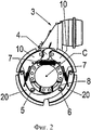
- фиг.2: разрез барабанного тормоза с расположенными внутри тормозными колодками;- figure 2: section of a drum brake with brake pads located inside;
- фиг.3: разрез барабанного тормоза по фиг.2 без подвешивания;- figure 3: a section of the drum brake of figure 2 without suspension;
- фиг.4а: вид сверху первой тормозной колодки согласно первому варианту выполнения; ^- figa: top view of the first brake pads according to the first embodiment; ^
- фиг.4b: вид сверху первой тормозной колодки согласно другому предпочтительному варианту выполнения;- fig.4b: top view of the first brake pads according to another preferred embodiment;
- фиг.5: вид сверху второй тормозной колодки;- figure 5: top view of the second brake pads;
- фиг.6а: предпочтительный вариант выполнения комплекта тормозных колодок на виде сверху;- figa: a preferred embodiment of a set of brake pads in a top view;
- фиг.6b: другой предпочтительный вариант выполнения комплекта тормозных колодок на виде сверху.- fig.6b: another preferred embodiment of a set of brake pads in a top view.
В нижеследующем описании фигур термины «вверху», «внизу», «слева», «справа», «спереди», «сзади» и т.д. относятся исключительно к выбранным на соответствующих фигурах примерным изображению и положению тормозной колодки, барабанного тормоза и других частей. Эти термины не следует понимать как ограничение, т.е. за счет различных рабочих положений или зеркально-симметричного выполнения и т.п. эти отношения могут изменяться.In the following description of the figures, the terms “top”, “bottom”, “left”, “right”, “front”, “back”, etc. refer solely to the approximate image selected on the respective figures and the position of the brake pad, drum brake and other parts. These terms should not be understood as limiting, i.e. due to various operating positions or mirror-symmetrical execution, etc. these relationships are subject to change.
Поз. 1 обозначен, в целом, вариант выполнения предложенного барабанного тормоза. Он содержит тормозной барабан 2 с внутренними тормозными колодками 10, 20 и исполнительное устройство 4, соединенное с расположенным на кронштейне 3 приводом. Как показано на фиг.2 и 3, внутри тормозного барабана 2 расположены более двух тормозных колодок 10, 20, в данном примере, в общей сложности, четыре тормозные колодки 10, 20. Каждая из них установлена с возможностью поворота на держателе 5, 6, причем держатели 5, 6 неподвижно закреплены на несущем диске 8.Pos. 1 shows, in general, an embodiment of the proposed drum brake. It contains a
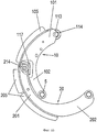
В показанном на фиг.4а и 4b варианте выполнения тормозная колодка 10 снабжена подошвой 103 держателя, имеющей опорную поверхность 104, на которой закреплена тормозная накладка 105 с поверхностью трения 106, контактирующая с внутренней поверхностью трения тормозного барабана 2.In the embodiment shown in FIGS. 4a and 4b, the
Подошва 103 соединена, например, сваркой с ребром 101, конец 116 которого через исполнительный элемент 113 посредством тормозной силы на тормозную колодку 10 приводится во взаимодействие с исполнительным устройством 4 на фиг.2 и 3.The sole 103 is connected, for example, by welding with a
Исполнительный элемент 113 выполнен в виде ролика 115 с ориентированной параллельно оси симметрии тормозного барабана 2 осью вращения, причем подвешивание ролика 115 происходит преимущественно посредством штифта 114, который фиксирован в пазу 112 в обращенной к исполнительному устройству 4 торцевой стенке ребра 101.The actuating
Другой конец ребра 101 имеет удлиненный участок 102, который проходит от подошвы 103 и на удаленном конце которого предпочтительно в виде отверстия выполнено сочленение 109 для выполненного в виде крепежного штифта держателя 5, 6, причем посредством сочленения 109 тормозная колодка 10 соединена с возможностью поворота с неподвижным несущим диском 108.The other end of the
На обращенной к тормозному барабану 2 стороне 117 удлиненного участка 102 предусмотрена направляющая для приведения в действие соседней тормозной колодки 20, выполненная, как показано, предпочтительно в виде направляющего элемента 118, вставленного в обращенную к тормозному барабану 2 сторону 117 удлиненного участка 102. Согласно варианту выполнения, представленному на фиг.4а, направляющий элемент 118 выполнен плоским и помещен в ребро 101 предпочтительно под углом к обращенной к тормозному барабану 2 стороне 117 удлиненного участка 102 и к подошве 103, причем один конец направляющего элемента 118 входит в близкую к подошве 103 зону ребра 101, а другой конец - в удлиненный участок 102. Переходы между свободным участком направляющего элемента 118 и обращенной к тормозному барабану 2 стороной 117 удлиненного участка 102 и близкой к подошве 103 зоной ребра 101 выполнены тупоугольными, предпочтительно в угловом диапазоне 130-160°.On the
В качестве альтернативы направляющий элемент 118 в варианте на фиг.4b, будучи выполнен ровным или слегка выгнутым, повторяя контур обращенной к тормозному барабану 2 стороны 117 удлиненного участка 102, может быть помещен в нее.Alternatively, the
В еще одном предпочтительном варианте направляющая может быть выполнена также в виде направляющей дорожки на обращенной к тормозному барабану 2 стороне 117 удлиненного участка 102.In another preferred embodiment, the guide may also be made in the form of a guide track on the
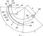
С этой направляющей тормозной колодки 10, как показано на фиг.2, 3, 6а, 6b, находится во взаимодействии исполнительный элемент 213 тормозной колодки 20. Последняя также выполнена с закрепленной на ребре 201 подошвой 203 ее держателя, имеющей опорную поверхность 204, на которой закреплена, по меньшей мере, одна тормозная накладка 205 в форме дуги окружности. На обращенном к соседней тормозной колодке 10 конце тормозной колодки 20 на ребре 201 предусмотрен исполнительный элемент 213, приводимый во взаимодействие с направляющей тормозной колодки 10, так что приводимая в действие исполнительным устройством 4 тормозная колодка 10 через исполнительный элемент 213 и направляющую на удлиненном участке 102 тормозной колодки 10 вызывает одновременное движение тормозной колодки 20. Исполнительный элемент 213, как и исполнительный элемент 113 тормозной колодки 10, выполнен предпочтительно в виде ролика 215 с ориентированной параллельно оси симметрии тормозного барабана 2 осью вращения, причем подвешивание ролика 215 происходит преимущественно посредством штифта 214, который фиксирован в пазу 212 в обращенной к направляющей тормозной колодки 10 торцевой стенке ребра 201.With this guide of the
На обращенном от исполнительного элемента 213 конце ребра 201 предусмотрен удлиненный участок 202, который проходит от подошвы 203 держателя тормозной колодки и на удаленном конце которого аналогично сочленению тормозной колодки 10 выполнено сочленение 209.An
В ребре 101 выполнено первое отверстие 110, служащее для удержания первого возвратного элемента 7, с помощью которого находящиеся во взаимодействии с исполнительным устройством 4 тормозные колодки 10 соединяются между собой. По окончании процесса торможения, при котором обе тормозные колодки 10 посредством исполнительного устройства 4 раздвигаются в положение торможения, выполненный предпочтительно в виде пружины растяжения возвратный элемент 7 при отводе исполнительного устройства 4 в его исходное положение тянет обе тормозные колодки 10 за счет растягивающего усилия возвратного элемента 7 снова в их исходное положение.A
Кроме того, в ребре 101 выполнено второе отверстие 111, служащее для удержания второго возвратного элемента 7, с помощью которого находящаяся во взаимодействии с исполнительным устройством 4 тормозная колодка 10 и приводимая в действие через ее направляющую соседняя тормозная колодка 20 соединяются между собой. Второй точкой удержания этого возвратного элемента 7 является при этом отверстие 201 в ребре 201 тормозной колодки 20. По окончании процесса торможения с помощью этого выполненного также в виде пружины растяжения возвратного элемента 7 тормозная колодка 20 в результате движения находящейся во взаимодействии с исполнительным устройством 4 тормозной колодки 10 возвращается в свое исходное положение также за счет растягивающего усилия возвратного элемента 7 в его исходное положение.In addition, a
Как видно на фиг.4а, 5, радиус R поверхности трения 106, 206 соответствующей тормозной накладки 105, 205 тормозных колодок 10, 20 и расстояние А между осью С тормозного барабана и сочленением 109, 209 тормозных колодок 10, 20 с держателем 5, 6 рассчитаны так, что отношение A/R составляет 0,6-0,9. Согласно одному особому варианту это отношение A/R составляет 0,6-0,7.As seen in figa, 5, the radius R of the
Размерные соотношения ребра 101, 201 с закрепленной на нем подошвой 103, 203 держателя тормозных колодок и тормозной накладкой 105, 205 и удлиненного участка 102, 202 соответствующих тормозных колодок 10, 20 рассчитаны так, что, если смотреть от оси С тормозного барабана, отношение занимаемого тормозной накладкой 105, 205 угла α, γ к углу β, δ, проходящему от обращенного от свободного конца Пб, 216 соответствующей тормозной колодки 10, 20 конца тормозной накладки 105, 205 до сочленения 109, 209, составляет 2/3-5. Согласно предпочтительному варианту это отношение угла α, γ к углу β, δ составляет 2/3-5/3.The size ratios of the
Сумма углов α, β тормозной колодки 10 и углов γ, δ тормозной колодки 10 составляет преимущественно 110-180°. Согласно одному особенно предпочтительному варианту выполнения сумма этих углов составляет 110-130°.The sum of the angles α, β of the
Как особенно хорошо видно на фиг.6а, в изображенном на ней комплекте тормозных колодок, состоящем из первичной тормозной колодки 10, находящейся во взаимодействии с исполнительным устройством, и вторичной тормозной колодки 20, выполненной с возможностью отклонения за первичную тормозную колодку 10, угол ε между свободным концом 116 первичной тормозной колодки 10 и сочленением 5, 6 вторичной тормозной колодки 20, находящейся во взаимодействии с ней, составляет более 180°.As is particularly clearly seen in Fig. 6a, in the set of brake pads shown on it, consisting of a
Как хорошо видно на фиг.2, 3, в предложенном барабанном тормозе, состоящем предпочтительно из двух комплектов из первичной 10 и вторичной 20 тормозных колодок каждый, все тормозные колодки приводятся в действие с помощью исполнительного устройства 4. Возможно также, чтобы одна вторичная тормозная колодка 20 была связана только с одной из первичных тормозных колодок 10.As can be clearly seen in figure 2, 3, in the proposed drum brake, preferably consisting of two sets of primary 10 and secondary 20 brake pads each, all brake pads are actuated using the
Удлиненные участки 102, 202 обеих вторичных тормозных колодок 20 расположены крест-накрест. На каждом из держателей 5, 6 в соответствующем сочленении 109, 209 установлено предпочтительно по одной первичной 10 и одной вторичной 20 тормозным колодкам.
Исполнительное устройство 4 выполнено предпочтительно в виде кулачка или кулачкового вала. Возможно также любое другое выполнение исполнительного устройства 4, например в виде тормозного клина или рабочего цилиндра. В качестве исполнительного устройства 4 возможны также электрические или электромеханические устройства, например с передаточным элементом.
Помимо варианта выполнения исполнительного элемента 113, 213 в виде ролика 115, 215 исполнительный элемент может быть выполнен также в виде сменного, компенсирующего зазор элемента. Кроме того, в исполнительный элемент 113, 213 может быть дополнительно интегрирован компенсатор износа.In addition to the embodiment of the
Изобретение не ограничено описанными выше вариантами его осуществления.The invention is not limited to the embodiments described above.
Важно, чтобы расположение и сочленение тормозных колодок в предложенном барабанном тормозе обеспечивали синхронное движение и большую поверхность трения, которые за счет равномерного распределения давления обеспечивают ему длительный срок службы.It is important that the location and articulation of the brake pads in the proposed drum brake provide synchronous movement and a large friction surface, which due to the uniform distribution of pressure provide it with a long service life.
Claims (17)
Applications Claiming Priority (3)
| Application Number | Priority Date | Filing Date | Title |
|---|---|---|---|
| DE102010021393A DE102010021393A1 (en) | 2010-05-25 | 2010-05-25 | Brake shoe of a drum brake, brake shoe set and drum brake |
| DE102010021393.4 | 2010-05-25 | ||
| PCT/EP2011/058354 WO2011147771A2 (en) | 2010-05-25 | 2011-05-23 | Brake shoe of a drum brake, brake shoe set, and drum brake |
Publications (2)
| Publication Number | Publication Date |
|---|---|
| RU2012156067A RU2012156067A (en) | 2014-06-27 |
| RU2569340C2 true RU2569340C2 (en) | 2015-11-20 |
Family
ID=44627859
Family Applications (1)
| Application Number | Title | Priority Date | Filing Date |
|---|---|---|---|
| RU2012156067/11A RU2569340C2 (en) | 2010-05-25 | 2011-05-23 | Brake pad of drum brake, set of brake pads and drum brake |
Country Status (9)
| Country | Link |
|---|---|
| US (1) | US20130126283A1 (en) |
| EP (1) | EP2577086B1 (en) |
| JP (1) | JP6120768B2 (en) |
| KR (1) | KR101852211B1 (en) |
| CN (1) | CN102906443B (en) |
| BR (1) | BR112012029736B1 (en) |
| DE (1) | DE102010021393A1 (en) |
| RU (1) | RU2569340C2 (en) |
| WO (1) | WO2011147771A2 (en) |
Families Citing this family (6)
| Publication number | Priority date | Publication date | Assignee | Title |
|---|---|---|---|---|
| US20140116819A1 (en) * | 2012-11-01 | 2014-05-01 | Bendix Spicer Foundation Brake Llc | Brake having lever and idler brake shoes |
| DE102013201111B4 (en) * | 2013-01-24 | 2015-11-05 | Saf-Holland Gmbh | Brake shoe for a drum brake |
| DE102014214098B3 (en) * | 2014-07-21 | 2015-12-10 | Saf-Holland Gmbh | braking system |
| CN105972197B (en) * | 2016-06-20 | 2018-03-30 | 裕克施乐塑料制品(太仓)有限公司 | A kind of automatic gear shift apparatus for planet gear train speed changer |
| CN107351067B (en) * | 2017-08-24 | 2023-12-26 | 苏州致康医疗机器人科技有限公司 | Doctor posture keeping power assisting system for operation application |
| CN108547888B (en) * | 2018-05-07 | 2020-04-28 | 西安航空制动科技有限公司 | Steel brake disc |
Citations (4)
| Publication number | Priority date | Publication date | Assignee | Title |
|---|---|---|---|---|
| US1629272A (en) * | 1927-05-17 | Brake | ||
| US1982360A (en) * | 1929-10-19 | 1934-11-27 | Eaton Mfg Co | Brake |
| SU1214956A1 (en) * | 1984-10-26 | 1986-02-28 | Белорусский Ордена Трудового Красного Знамени Политехнический Институт | Normally-open multiblock brake |
| EP0216608A2 (en) * | 1985-09-20 | 1987-04-01 | LUCAS INDUSTRIES public limited company | Internal shoe drum brake |
Family Cites Families (26)
| Publication number | Priority date | Publication date | Assignee | Title |
|---|---|---|---|---|
| USRE22586E (en) * | 1945-01-02 | Brake mechanism | ||
| US1875392A (en) * | 1932-09-06 | parker | ||
| GB243053A (en) * | 1924-08-18 | 1925-11-18 | John Meredith Rubury | Improvements in and relating to brakes |
| GB244037A (en) * | 1924-12-02 | 1926-06-24 | Bendix Brake Co | Improvements relating to brake mechanism |
| US1689767A (en) * | 1926-12-04 | 1928-10-30 | Bendix Brake Co | Duplex brake |
| US1758066A (en) * | 1927-08-01 | 1930-05-13 | Midland Steel Prod Co | Brake structure |
| US1923437A (en) * | 1928-04-11 | 1933-08-22 | Brunt Van | Brake |
| US1925286A (en) * | 1930-03-12 | 1933-09-05 | Eaton Mfg Co | Brake |
| US1875945A (en) * | 1930-03-12 | 1932-09-06 | Eaton Mfg Co | Brake |
| US1904997A (en) * | 1930-05-17 | 1933-04-25 | Bendix Brake Co | Brake |
| US1946032A (en) * | 1930-11-24 | 1934-02-06 | Bendix Brake Co | Brake |
| US2176398A (en) * | 1937-08-20 | 1939-10-17 | Hydraulic Brake Co | Brake |
| US2196520A (en) * | 1938-09-02 | 1940-04-09 | Butler James | Brake mechanism |
| US2372322A (en) * | 1942-05-11 | 1945-03-27 | Bendix Aviat Corp | Brake |
| US2575706A (en) * | 1946-04-15 | 1951-11-20 | Farkas Pierre | Vehicle brake |
| US2828835A (en) * | 1953-10-27 | 1958-04-01 | Westinghouse Freins & Signaux | Transversely expanding type wheel brake |
| DE1011677B (en) | 1955-04-05 | 1957-07-04 | Stromag Maschf | Switchable elastic jaw friction clutch or brake |
| US3135361A (en) * | 1961-03-02 | 1964-06-02 | Arthur C Roberto | Internally expanding brakes |
| US3205978A (en) * | 1963-01-22 | 1965-09-14 | John H Broseke | Brake having concentrically mounted shoes |
| FR2175426A7 (en) * | 1972-03-03 | 1973-10-19 | Sauer Achsenfab | |
| NL7413706A (en) * | 1973-11-24 | 1975-05-27 | Bergische Achsen Kotz Soehne | RETAINING ELEMENT FOR A PRESSURE ROLLER IN DRUM BRAKES. |
| AR215543A1 (en) * | 1978-02-03 | 1979-10-15 | Eaton Corp | IMPROVED BRAKE ASSEMBLY |
| US4905800A (en) * | 1986-09-05 | 1990-03-06 | Eaton Corporation | S-cam for drum brake |
| JP3974963B2 (en) * | 1996-11-19 | 2007-09-12 | 本田技研工業株式会社 | Drum brake for vehicles |
| DE102005049060B4 (en) * | 2004-10-26 | 2016-12-08 | Knorr-Bremse Systeme für Nutzfahrzeuge GmbH | Brake shoe for a drum brake, drum brake with a brake shoe and brake system with a drum brake and a brake shoe |
| JP7117114B2 (en) * | 2018-03-05 | 2022-08-12 | ローム株式会社 | chip resistor |
-
2010
- 2010-05-25 DE DE102010021393A patent/DE102010021393A1/en not_active Ceased
-
2011
- 2011-05-23 CN CN201180025766.XA patent/CN102906443B/en active Active
- 2011-05-23 EP EP11729265.6A patent/EP2577086B1/en active Active
- 2011-05-23 KR KR1020127033052A patent/KR101852211B1/en active IP Right Grant
- 2011-05-23 BR BR112012029736-8A patent/BR112012029736B1/en active IP Right Grant
- 2011-05-23 RU RU2012156067/11A patent/RU2569340C2/en active
- 2011-05-23 WO PCT/EP2011/058354 patent/WO2011147771A2/en active Application Filing
- 2011-05-23 JP JP2013511630A patent/JP6120768B2/en active Active
-
2012
- 2012-11-20 US US13/682,234 patent/US20130126283A1/en not_active Abandoned
Patent Citations (4)
| Publication number | Priority date | Publication date | Assignee | Title |
|---|---|---|---|---|
| US1629272A (en) * | 1927-05-17 | Brake | ||
| US1982360A (en) * | 1929-10-19 | 1934-11-27 | Eaton Mfg Co | Brake |
| SU1214956A1 (en) * | 1984-10-26 | 1986-02-28 | Белорусский Ордена Трудового Красного Знамени Политехнический Институт | Normally-open multiblock brake |
| EP0216608A2 (en) * | 1985-09-20 | 1987-04-01 | LUCAS INDUSTRIES public limited company | Internal shoe drum brake |
Also Published As
| Publication number | Publication date |
|---|---|
| CN102906443A (en) | 2013-01-30 |
| US20130126283A1 (en) | 2013-05-23 |
| WO2011147771A2 (en) | 2011-12-01 |
| KR20130076827A (en) | 2013-07-08 |
| JP6120768B2 (en) | 2017-04-26 |
| EP2577086A2 (en) | 2013-04-10 |
| BR112012029736B1 (en) | 2021-02-23 |
| DE102010021393A1 (en) | 2011-12-01 |
| EP2577086B1 (en) | 2018-03-14 |
| BR112012029736A2 (en) | 2016-08-09 |
| WO2011147771A3 (en) | 2012-06-21 |
| CN102906443B (en) | 2016-05-18 |
| RU2012156067A (en) | 2014-06-27 |
| KR101852211B1 (en) | 2018-04-25 |
| JP2013526693A (en) | 2013-06-24 |
Similar Documents
| Publication | Publication Date | Title |
|---|---|---|
| RU2569340C2 (en) | Brake pad of drum brake, set of brake pads and drum brake | |
| KR102557204B1 (en) | Disc brakes and brake lining sets for commercial vehicles | |
| RU2745950C2 (en) | Multi-link hinge | |
| AU2017376561A1 (en) | Disc brake for a utility vehicle, and brake pad set | |
| CN105683608B (en) | Brake apparatus | |
| JP7307752B2 (en) | Deceleration hinge for furniture | |
| CN106662182B (en) | Disc brake assembly and disk brake for rail vehicle | |
| KR101957535B1 (en) | A rail vehicle brake actuator with a brake block holder | |
| CN105452702B (en) | Brake apparatus | |
| JP2013526693A5 (en) | ||
| RU2670850C9 (en) | Braking pad for the drum brake with displaced cam followers | |
| CN101985963B (en) | Caliper disc brake capable of symmetrically braking | |
| CN103128638B (en) | A kind of derusting device of total sub-semigroup steel tube derusting machine | |
| JP2004512485A5 (en) | ||
| RU2002113911A (en) | SHAFT-DRUM BRAKE WITH PADS OF JOINT ACTION WITH MANY DEGREES OF FREEDOM | |
| CN209184775U (en) | A kind of pivot structure and earphone | |
| CN202883825U (en) | Asymmetric cam type brake | |
| US20090159379A1 (en) | Drum Brakes | |
| US20040069575A1 (en) | Independent springing guides for floating rotors | |
| BR112019011178B1 (en) | DISC BRAKE FOR UTILITY VEHICLE AND BRAKE PAD ASSEMBLY | |
| RU96118478A (en) | MECHANICAL DRIVE FOR DRUM BRAKE TYPE | |
| CN205605699U (en) | Automobile -used braking pincers | |
| SU1686236A1 (en) | Drum brake | |
| SU1682675A1 (en) | Drum-cheek brake | |
| CN203412999U (en) | Sliding caliper disc brake |