RU2564379C1 - Platformless inertial attitude-and-heading reference - Google Patents
Platformless inertial attitude-and-heading reference Download PDFInfo
- Publication number
- RU2564379C1 RU2564379C1 RU2014119781/28A RU2014119781A RU2564379C1 RU 2564379 C1 RU2564379 C1 RU 2564379C1 RU 2014119781/28 A RU2014119781/28 A RU 2014119781/28A RU 2014119781 A RU2014119781 A RU 2014119781A RU 2564379 C1 RU2564379 C1 RU 2564379C1
- Authority
- RU
- Russia
- Prior art keywords
- block
- sensors
- unit
- matrix
- kalman filter
- Prior art date
Links
Images


Abstract
Description
Изобретение относится к измерительной технике и может быть использовано для морских, воздушных и наземных объектов. Задачей изобретения является повышение точности бесплатформенной инерциальной навигационной системы (БИНС) путем создания устройства непрерывной коррекции инерциальной курсовертикали.The invention relates to measuring equipment and can be used for marine, air and ground objects. The objective of the invention is to improve the accuracy of the strapdown inertial navigation system (SINS) by creating a device for continuous correction of inertial course-line vertical.
Классическим алгоритмом вычисления углов ориентации является пересчет показаний датчиков угловых скоростей (ДУС) / проекций абсолютной угловой скорости - ωx, ωy, ωz / в угловые скорости ![]()
![]()
![]()
![]()
![]()
![]()
Известна бесплатформенная инерциальная курсовертикаль, описанная в патенте RU 2249791 C2, МПК G01C 21/16, опубл. 10.04.2005, принятая нами за прототип.Known strapdown inertial kursertical, described in patent RU 2249791 C2, IPC G01C 21/16, publ. 04/10/2005, accepted by us as a prototype.
Данная бесплатформенная инерциальная курсовертикаль с контуром коррекции содержит трехканальный блок датчиков угловых скоростей (ДУС), трехканальный блок датчиков линейных ускорений (ДЛУ), блок интеграторов, формирователь производных от углов ориентации, блок коррекции, блок вычисления наблюдаемой вертикали, блок вычисления ошибок курсовертикали, фильтр, блок выставки курса.This strap-down inertial course-line with a correction loop contains a three-channel block of angular velocity sensors (DLS), a three-channel block of linear acceleration sensors (DLU), a block of integrators, a shaper of derivatives of orientation angles, a correction block, a block for calculating the observed vertical, a block for calculating errors of the vertical, filter, course show unit.
Угловые скорости, измеренные трехканальным блоком ДУС и преобразованные в производные от углов ориентации, содержат ошибки, обусловленные систематическими и случайными погрешностями измерений. Предполагается, что при интегрировании угловых скоростей ошибка не накапливается из-за вычитания постоянных составляющих ошибки. Крен и тангаж корректируются блоком коррекции с использованием сигналов ДЛУ. Курс корректируется блоком коррекции с использованием блока выставки курса. Ошибки курсовертикали компенсируются в блоке коррекции, проходя через фильтр высоких частот.The angular velocities measured by the three-channel block of the TLS and converted into derivatives of the orientation angles contain errors due to systematic and random measurement errors. It is assumed that when integrating angular velocities, the error does not accumulate due to the subtraction of the constant components of the error. The roll and pitch are corrected by a correction unit using DLU signals. The course is adjusted by the correction block using the course show block. Heading errors are compensated in the correction block by passing through a high-pass filter.
Недостаток данного устройства заключается в том, что при маневрировании ЛА моменты времени, когда оценки крена и тангажа обладают достаточной точностью, могут возникать недопустимо редко из-за наличия в сигналах акселерометров медленно меняющихся и быстро меняющихся линейных и поворотных ускорений. Это может привести к возникновению значительных погрешностей в показаниях крена и тангажа.The disadvantage of this device is that when maneuvering the aircraft, the moments of time when the roll and pitch estimates are accurate enough can occur unacceptably rarely due to the presence of slowly changing and rapidly changing linear and rotational accelerations in the accelerometer signals. This can lead to significant errors in roll and pitch readings.
Целью изобретения является обеспечение непрерывной коррекции БИНС по углам крена и тангажа с требуемой точностью, в том числе и в динамических режимах полета.The aim of the invention is the provision of continuous correction SINS in roll angles and pitch with the required accuracy, including in dynamic flight modes.
Поставленная цель достигается за счет того, что в бесплатформенную инерциальную курсовертикаль, содержащую трехкомпонентный блок датчиков угловых скоростей, трехкомпонентный блок датчиков линейных ускорений, корректор курса и интегрирующий блок, выходы которых подключены соответственно к первому, второму, третьему и четвертому входам вычислительного блока, дополнительно введены блок формирования матрицы направляющих косинусов, фильтр Калмана и блок формирования функций измерений, причем первые входы блока формирования направляющих косинусов, фильтра Калмана и блока формирования функций измерений соединены с выходом трехкомпонентного блока датчиков угловых скоростей, вторые входы фильтра Калмана и блока формирования функций измерений соединены с выходом трехкомпонентного блока датчиков линейных ускорений, выход блока формирования матрицы направляющих косинусов подключен к интегрирующему блоку, выход фильтра Калмана подключен к второму входу блока формирования матрицы направляющих косинусов и к третьему входу блока формирования функций измерений, выход которого подключен к третьему входу фильтра Калмана.This goal is achieved due to the fact that in the strapdown inertial directional line containing a three-component block of angular velocity sensors, a three-component block of linear acceleration sensors, a course corrector and an integrating block, the outputs of which are connected respectively to the first, second, third and fourth inputs of the computing unit, are additionally introduced a block for generating a matrix of guide cosines, a Kalman filter and a block for generating measurement functions, the first inputs of a block for forming guides x cosines, a Kalman filter and a block for generating measurement functions are connected to the output of a three-component block of angular velocity sensors, the second inputs of a Kalman filter and a block for forming measurement functions are connected to the output of a three-component block of linear acceleration sensors, the output of the block forming a matrix of guide cosines is connected to an integrating block, the filter output Kalman is connected to the second input of the block forming the matrix of guide cosines and to the third input of the block forming the measurement functions, the output to orogo connected to the third input of the Kalman filter.
Сущность изобретения поясняется чертежами, где приведены:The invention is illustrated by drawings, which show:
на фиг. 1 - структурная схема заявляемого устройства;in FIG. 1 is a structural diagram of the inventive device;
на фиг. 2, 3 графически представлены результаты обработки полетных данных вертолета с заявляемой курсовертикалью (оценки тангажа - фиг. 2 и оценки крена - фиг. 3).in FIG. 2, 3 graphically presents the results of processing the flight data of a helicopter with the claimed heading (pitch estimates - Fig. 2 and roll estimates - Fig. 3).
Бесплатформенная инерциальная курсовертикаль (фиг. 1) содержит трехкомпонентный блок 1 датчиков угловых скоростей, трехкомпонентный блок 2 датчиков линейных ускорений, корректор 3 курса, вычислительный блок 4, блок 5 формирования матрицы направляющих косинусов, интегрирующий блок 6, фильтр 7 Калмана и блок 8 формирования функций измерений, соединенные между собой соответствующим образом.The inertial inertial course-line vertical (Fig. 1) contains a three-component block 1 of angular velocity sensors, a three-component block 2 of linear acceleration sensors, a 3-course corrector, a computational block 4, a
Предлагаемая структурная схема устройства обеспечивает адаптивную (маятниковую) коррекцию курсовертикали БИНС, реализуемую посредством фильтра 7 Калмана, в котором коэффициент усиления изменяется с учетом текущих значений модулей перегрузки и угловой скорости в блоке 8.The proposed block diagram of the device provides an adaptive (pendulum) correction of the SINS vertical line, implemented by the Kalman filter 7, in which the gain is changed taking into account the current values of the overload modules and angular velocity in block 8.
Изменения крена и тангажа описываются уравнениями Пуассона в интегрирующем блоке 6. Уточнение углов ориентации происходит в блоке направляющих косинусов 5. В блоке 8 происходит преобразование сигналов акселерометров ДЛУ блока 2, в зависимости от текущих параметров полета, которые используются для адаптивного оценивания вектора состояния при помощи фильтра 7 Калмана. За счет этого зависимость точности маятниковой коррекции от вида движения ЛА ослабляется до уровня, позволяющего использовать датчики ДУС и ДЛУ средней и низкой точности, в том числе микромеханического типа. Курс БИНС корректируется по сигналам магнитометрических датчиков 3.The roll and pitch changes are described by the Poisson equations in the integrating block 6. The orientation angles are updated in the block of
Суть работы устройства излагается ниже.The essence of the device is described below.
По измерениям блоков датчиков ДУС 1 и ДЛУ 2 определяются текущие углы крена γ, тангжа ϑ и рыскания ψ из уравнений ПуассонаFrom the measurements of the sensor blocks ДУС 1 and ДРУ 2, the current angles of roll γ, pitch ϑ and yaw ψ are determined from the Poisson equations
![]()
![]()
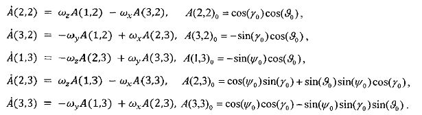
где матрица направляющих косинусов А, задающая переход от навигационной системы координат (СК) PNUE к связанной СК OXYZ, и кососимметрическая матрица Ω имеют следующий вид:where the matrix of guide cosines A, defining the transition from the navigation coordinate system (SK) PNUE to the connected SK OXYZ, and the skew-symmetric matrix Ω have the following form:

Матричное уравнение Пуассона (1) решается в дискретном виде с учетом начальных условий матрицы направляющих косинусов А, то есть задаются начальные значения крена γ и тангажа, ϑ и угла рысканья ψ,The matrix Poisson equation (1) is solved in discrete form, taking into account the initial conditions of the matrix of guide cosines A, that is, the initial values of the roll γ and pitch, ϑ and the yaw angle ψ, are set

Расчет крена и тангажа по матрице поворота выполняется в вычислительном блоке 4 с помощью соотношений:![]()
![]()
Вектор состояния адаптивного фильтра 7 Калмана представлен ниже:The state vector of adaptive Kalman filter 7 is presented below:
![]()
![]()
где ϑ - тангаж, γ - крен, V - модуль вектора земной скорости на момент i,where ϑ - pitch, γ - roll, V - modulus of the velocity vector at the time i,
i - номер дискретного момента времени измерений датчиков. При i=0, ![]()
![]()
![]()
![]()
Вектор наблюдений, обозначаемый далее Z, содержит измерения акселерометров, поступающих с блока 2 датчиков линейных ускорений, и параметры полета ЛАThe observation vector, denoted below Z, contains measurements of accelerometers coming from block 2 of linear acceleration sensors, and flight parameters of the aircraft

Здесь vi - вектор ошибок измерений с заданной постоянной ковариационной матрицей R. Функции fx, fy, fz определяют связь измерений перегрузок с параметрами полета. Точные соотношения для этих функций имеют вид:Here v i is the vector of measurement errors with a given constant covariance matrix R. The functions f x , f y , f z determine the relationship between the measurements of overloads and flight parameters. The exact relationships for these functions are:

Здесь Vx, Vy, Vz - проекции вектора земной скорости на связанные оси ЛА.Here V x , V y , V z are the projections of the earth's velocity vector on the connected axis of the aircraft.
Полный учет соотношений (7) при ограничении состава датчиков только ДЛУ и ДУС не представляется возможным, поэтому принимается упрощающее допущение о малости углов атаки и скольжения, а также допущение о постоянстве модуля путевой скорости на интервале дискретизации Δt.It is not possible to fully take into account relations (7) while limiting the composition of the sensors to only DLN and TLS, therefore, the simplifying assumption is made that the angles of attack and slip are small, as well as the assumption that the modulus of the ground speed in the sampling interval Δt is constant.
При этом имеют место соотношения: Vx=V, ![]()
![]()
![]()
![]()

С учетом (7) матрица Якоби вектора наблюдений (8) имеет видIn view of (7), the Jacobi matrix of the observation vector (8) has the form

Соотношения (8) являются приближенными. Степень приближения зависит от отклонения модуля перегрузки от единицы. Чем больше модуль перегрузки отличается от единицы, тем менее точны эти уравнения и тем больше дисперсии ![]()
![]()
![]()
![]()
![]()
![]()
![]()
![]()
где ![]()
![]()
Здесь k0,k1 - коэффициенты.Here k 0 , k 1 are the coefficients.
Текущий вектор состояния (5) рассчитывается по уравнениям Пуассона (1) с учетом (2), (3). При этом уравнения объекта принимаются в виде:The current state vector (5) is calculated according to the Poisson equations (1) taking into account (2), (3). In this case, the equations of the object are accepted in the form:
![]()
![]()
Здесь xiq - вектор, в котором компоненты крена и тангажа рассчитаны по соотношениям (3), а компонента скорости принимается равной ее априорному значению на момент текущих измерений; wi - вектор возмущений с ковариационной матрицей Qi:Here x iq is the vector in which the roll and pitch components are calculated according to relations (3), and the velocity component is taken equal to its a priori value at the time of the current measurements; w i is the perturbation vector with the covariance matrix Q i :

Случайные процессы ![]()
![]()
![]()
![]()
![]()
![]()
![]()
![]()
![]()
![]()
![]()
![]()
Фильтр Калмана строится для оценивания вектора состояния (5) с дискретной моделью объекта (3) и дискретной моделью наблюдения (9) с учетом (10).The Kalman filter is constructed to estimate the state vector (5) with a discrete object model (3) and a discrete observation model (9) taking into account (10).
Для запуска алгоритма фильтра используются статистики х0, ![]()
![]()
При очередном i-ом отсчете измерений датчиков фильтр 7 Калмана определяет статистики ![]()
![]()
![]()
![]()
![]()
![]()
![]()
![]()
![]()
![]()
Расчет статистик апостериорного распределения ![]()
![]()

Здесь Ki - матричный коэффициент усиления фильтра; ![]()
![]()
Работа заявляемого устройства проверялась на вертолете Robinson и оценивалась посредством обработки полетных данных вертолета, для чего:The operation of the inventive device was tested on a Robinson helicopter and evaluated by processing the flight data of the helicopter, for which:
1. Определялась ориентация ЛА по алгоритму комплексирования измерений приемника СНС с датчиками ДУС и ДЛУ на скользящем интервале наблюдений.1. The aircraft orientation was determined by the algorithm for integrating the measurements of the SNA receiver with sensors of the TLS and DLU on a moving observation interval.
2. Определялись крен и тангаж по алгоритму при помощи бесплатформенной инерциальной курсовертикали с маятниковой коррекцией.2. The roll and pitch were determined according to the algorithm using a strapdown inertial vertical course with pendulum correction.
В задачах обработки полетных данных вертолета (фиг. 2 и 3) требовалось соблюдение близости оценок крена и тангажа к оценкам, полученным иным способом, а именно - с помощью алгоритма ориентации при комплексировании информации от ДУС и ДЛУ с измерениями проекций земной скорости, поступающими от приемника СНС. Также проверялось соответствие получаемых оценок показаниям контрольного прибора.In the tasks of processing the flight data of the helicopter (Figs. 2 and 3), it was necessary to observe the proximity of the roll and pitch estimates to the estimates obtained in a different way, namely, using the orientation algorithm when combining information from the TLS and DLN with the measurements of the projections of the ground velocity coming from the receiver SNA. Also, the correspondence of the obtained estimates to the indications of the control device was checked.
Для случаев, когда положение ЛА является близким к установившемуся, имеет место идеальный случай адаптивной маятниковой коррекции. При этом оценки крена и тангажа, определяемые по фильтру Калмана, заменяются оценками, вычисляемыми непосредственно по показаниям ДЛУ в вычислителе.For cases when the position of the aircraft is close to steady, there is an ideal case of adaptive pendulum correction. In this case, the roll and pitch estimates determined by the Kalman filter are replaced by the estimates calculated directly from the readings of the DLU in the computer.
![]()
![]()
Таким образом, с помощью предлагаемого устройства решается задача оценивания вектора (5) ![]()
![]()
Расчеты показывают, что устройство работает при изменении углов тангажа и крена в пределах абсолютных значений до 70-80 градусов.Calculations show that the device works when changing pitch and roll angles within absolute values up to 70-80 degrees.
Техническим результатом использования изобретения является повышение точности и обеспечение непрерывности коррекции углов тангажа и крена в условиях маневрирования в полете. Изобретение позволяет использовать датчики ДУС и ДЛУ средней и низкой точности, в том числе микромеханического типа.The technical result of the use of the invention is to increase accuracy and ensure continuity of the correction of pitch and roll angles under conditions of maneuvering in flight. The invention allows the use of sensors DUS and DLU medium and low accuracy, including micromechanical type.
Заявляемое устройство является реализуемым и может быть использовано на всех типах ЛА. В качестве датчиков угловых скоростей могут быть использованы микромеханические гироскопические датчики, при этом блок формирования матрицы направляющих косинусов, фильтр Калмана и блок формирования функций измерений могут быть реализованы на стандартных элементах вычислительной техники.The inventive device is feasible and can be used on all types of aircraft. Micromechanical gyroscopic sensors can be used as angular velocity sensors, while the block for generating the matrix of guide cosines, the Kalman filter, and the block for generating measurement functions can be implemented on standard elements of computer technology.
Claims (1)
Priority Applications (1)
| Application Number | Priority Date | Filing Date | Title |
|---|---|---|---|
| RU2014119781/28A RU2564379C1 (en) | 2014-05-16 | 2014-05-16 | Platformless inertial attitude-and-heading reference |
Applications Claiming Priority (1)
| Application Number | Priority Date | Filing Date | Title |
|---|---|---|---|
| RU2014119781/28A RU2564379C1 (en) | 2014-05-16 | 2014-05-16 | Platformless inertial attitude-and-heading reference |
Publications (1)
| Publication Number | Publication Date |
|---|---|
| RU2564379C1 true RU2564379C1 (en) | 2015-09-27 |
Family
ID=54251074
Family Applications (1)
| Application Number | Title | Priority Date | Filing Date |
|---|---|---|---|
| RU2014119781/28A RU2564379C1 (en) | 2014-05-16 | 2014-05-16 | Platformless inertial attitude-and-heading reference |
Country Status (1)
| Country | Link |
|---|---|
| RU (1) | RU2564379C1 (en) |
Cited By (6)
| Publication number | Priority date | Publication date | Assignee | Title |
|---|---|---|---|---|
| RU2594631C1 (en) * | 2015-05-08 | 2016-08-20 | Открытое акционерное общество Московский научно-производственный комплекс "Авионика" имени О.В. Успенского (ОАО МНПК "Авионика") | Method of determining spatial orientation angles of aircraft and device therefor |
| RU2643201C2 (en) * | 2016-05-11 | 2018-01-31 | Открытое акционерное общество Московский научно-производственный комплекс "Авионика" имени О.В. Успенского (ОАО МНПК "Авионика") | Strap down inertial attitude-and-heading reference |
| RU2647205C2 (en) * | 2016-06-01 | 2018-03-14 | Открытое акционерное общество Московский научно-производственный комплекс "Авионика" имени О.В. Успенского (ОАО МНПК "Авионика") | Adaptive strap down inertial attitude-and-heading reference system |
| RU2713997C2 (en) * | 2017-05-30 | 2020-02-11 | Акционерное общество Московский научно-производственный комплекс "Авионика" имени О.В. Успенского (АО МНПК "Авионика") | Bank angle corrector for refining aircraft trajectory |
| RU2749152C1 (en) * | 2020-06-19 | 2021-06-07 | Акционерное общество Московский научно-производственный комплекс "Авионика" имени О.В. Успенского (АО МНПК "Авионика") | Adaptive attitude angle corrector for strapdown inertial navigation system |
| RU2786133C1 (en) * | 2022-08-12 | 2022-12-19 | Федеральное государственное бюджетное образовательное учреждение высшего образования "Саратовский государственный технический университет имени Гагарина Ю.А." (СГТУ имени Гагарина Ю.А.) | Meter of external disturbing forces and moments of these forces acting on the fuselage of a single-rotor helicopter |
Citations (4)
| Publication number | Priority date | Publication date | Assignee | Title |
|---|---|---|---|---|
| GB2323989A (en) * | 1997-04-02 | 1998-10-07 | Caterpillar Inc | Monitoring combined inertial/GPS system |
| US6408245B1 (en) * | 2000-08-03 | 2002-06-18 | American Gnc Corporation | Filtering mechanization method of integrating global positioning system receiver with inertial measurement unit |
| RU2249791C2 (en) * | 2003-06-24 | 2005-04-10 | Федеральное государственное унитарное предприятие "Конструкторское бюро "Луч" | Platform-free inertial attitude-and-heading reference system |
| RU2487318C1 (en) * | 2012-02-14 | 2013-07-10 | Олег Степанович Салычев | Platform-free inertial attitude and heading reference system based on sensitive elements of medium accuracy |
-
2014
- 2014-05-16 RU RU2014119781/28A patent/RU2564379C1/en active
Patent Citations (4)
| Publication number | Priority date | Publication date | Assignee | Title |
|---|---|---|---|---|
| GB2323989A (en) * | 1997-04-02 | 1998-10-07 | Caterpillar Inc | Monitoring combined inertial/GPS system |
| US6408245B1 (en) * | 2000-08-03 | 2002-06-18 | American Gnc Corporation | Filtering mechanization method of integrating global positioning system receiver with inertial measurement unit |
| RU2249791C2 (en) * | 2003-06-24 | 2005-04-10 | Федеральное государственное унитарное предприятие "Конструкторское бюро "Луч" | Platform-free inertial attitude-and-heading reference system |
| RU2487318C1 (en) * | 2012-02-14 | 2013-07-10 | Олег Степанович Салычев | Platform-free inertial attitude and heading reference system based on sensitive elements of medium accuracy |
Non-Patent Citations (1)
| Title |
|---|
| РИВКИН С.С. Метод оптимальной фильтрации Калмана и его применение в инерциальных навигационных системах. - Л.: Судостроение, 1974, 219 с. * |
Cited By (6)
| Publication number | Priority date | Publication date | Assignee | Title |
|---|---|---|---|---|
| RU2594631C1 (en) * | 2015-05-08 | 2016-08-20 | Открытое акционерное общество Московский научно-производственный комплекс "Авионика" имени О.В. Успенского (ОАО МНПК "Авионика") | Method of determining spatial orientation angles of aircraft and device therefor |
| RU2643201C2 (en) * | 2016-05-11 | 2018-01-31 | Открытое акционерное общество Московский научно-производственный комплекс "Авионика" имени О.В. Успенского (ОАО МНПК "Авионика") | Strap down inertial attitude-and-heading reference |
| RU2647205C2 (en) * | 2016-06-01 | 2018-03-14 | Открытое акционерное общество Московский научно-производственный комплекс "Авионика" имени О.В. Успенского (ОАО МНПК "Авионика") | Adaptive strap down inertial attitude-and-heading reference system |
| RU2713997C2 (en) * | 2017-05-30 | 2020-02-11 | Акционерное общество Московский научно-производственный комплекс "Авионика" имени О.В. Успенского (АО МНПК "Авионика") | Bank angle corrector for refining aircraft trajectory |
| RU2749152C1 (en) * | 2020-06-19 | 2021-06-07 | Акционерное общество Московский научно-производственный комплекс "Авионика" имени О.В. Успенского (АО МНПК "Авионика") | Adaptive attitude angle corrector for strapdown inertial navigation system |
| RU2786133C1 (en) * | 2022-08-12 | 2022-12-19 | Федеральное государственное бюджетное образовательное учреждение высшего образования "Саратовский государственный технический университет имени Гагарина Ю.А." (СГТУ имени Гагарина Ю.А.) | Meter of external disturbing forces and moments of these forces acting on the fuselage of a single-rotor helicopter |
Similar Documents
| Publication | Publication Date | Title |
|---|---|---|
| RU2373498C2 (en) | Navigation complex, velocity and coordinates' calculation, gimballess inertial attitude-and-heading reference system, correction method for inertial transducers and device for its implementation | |
| US8442703B2 (en) | Turning-stabilized estimation of the attitude angles of an aircraft | |
| RU2564379C1 (en) | Platformless inertial attitude-and-heading reference | |
| RU2564380C1 (en) | Correction method of strap-down inertial navigation system | |
| CN106403940B (en) | A kind of unmanned plane during flying navigation system elevation information fusion method of anti-atmospheric parameter drift | |
| RU2348903C1 (en) | Method of determination of navigating parameters by gimballess inertial navigating system | |
| RU2749152C1 (en) | Adaptive attitude angle corrector for strapdown inertial navigation system | |
| JP2011227017A (en) | Device and method for attitude estimation of moving body using inertial sensor, magnetic sensor, and speed meter | |
| US10025891B1 (en) | Method of reducing random drift in the combined signal of an array of inertial sensors | |
| RU2647205C2 (en) | Adaptive strap down inertial attitude-and-heading reference system | |
| RU2539140C1 (en) | Integrated strapdown system of navigation of average accuracy for unmanned aerial vehicle | |
| CN111189442A (en) | Multi-source navigation information state prediction method of unmanned aerial vehicle based on CEPF | |
| JP2014240266A (en) | Sensor drift amount estimation device and program | |
| RU2382988C1 (en) | Strapdown inertial reference system on "coarse" detecting elements | |
| RU2373562C2 (en) | Method and device for controlling horizontal orientation of aircraft | |
| Ducard et al. | Strategies for sensor-fault compensation on UAVs: Review, discussions & additions | |
| García et al. | Analysis of sensor data and estimation output with configurable UAV platforms | |
| RU2487318C1 (en) | Platform-free inertial attitude and heading reference system based on sensitive elements of medium accuracy | |
| RU2635820C1 (en) | Method of correction of platform-free inertial navigation system | |
| RU2754396C1 (en) | Adaptive method for correcting orientation angles of strapdown ins | |
| Emran et al. | A cascaded approach for quadrotor's attitude estimation | |
| Michailidis et al. | A software in the loop (SIL) Kalman and complementary filter implementation on x-plane for UAVs | |
| RU2502049C1 (en) | Small-size platformless inertial navigation system of medium accuracy, corrected from system of air signals | |
| US8812235B2 (en) | Estimation of N-dimensional parameters while sensing fewer than N dimensions | |
| Khaghani et al. | Evaluation of wind effects on UAV autonomous navigation based on vehicle dynamic model |