RU2563243C1 - Method to produce filled polyurethanes and installation for its realisation - Google Patents
Method to produce filled polyurethanes and installation for its realisation Download PDFInfo
- Publication number
- RU2563243C1 RU2563243C1 RU2014135242/04A RU2014135242A RU2563243C1 RU 2563243 C1 RU2563243 C1 RU 2563243C1 RU 2014135242/04 A RU2014135242/04 A RU 2014135242/04A RU 2014135242 A RU2014135242 A RU 2014135242A RU 2563243 C1 RU2563243 C1 RU 2563243C1
- Authority
- RU
- Russia
- Prior art keywords
- components
- mixing
- high pressure
- solid filler
- hydraulic
- Prior art date
Links
- 229920002635 polyurethane Polymers 0.000 title claims abstract description 33
- 239000004814 polyurethane Substances 0.000 title claims abstract description 33
- 238000000034 method Methods 0.000 title claims abstract description 32
- 238000009434 installation Methods 0.000 title claims abstract description 21
- 239000000945 filler Substances 0.000 claims abstract description 61
- 239000000203 mixture Substances 0.000 claims abstract description 45
- 239000007787 solid Substances 0.000 claims abstract description 45
- 239000007788 liquid Substances 0.000 claims abstract description 31
- 238000004519 manufacturing process Methods 0.000 claims abstract description 20
- 239000000654 additive Substances 0.000 claims abstract description 4
- 125000002887 hydroxy group Chemical group [H]O* 0.000 claims abstract description 4
- 239000012948 isocyanate Substances 0.000 claims abstract description 4
- 150000002513 isocyanates Chemical class 0.000 claims abstract description 4
- VYPSYNLAJGMNEJ-UHFFFAOYSA-N Silicium dioxide Chemical compound O=[Si]=O VYPSYNLAJGMNEJ-UHFFFAOYSA-N 0.000 claims description 10
- 239000000463 material Substances 0.000 claims description 7
- 239000004576 sand Substances 0.000 claims description 7
- 229920002209 Crumb rubber Polymers 0.000 claims description 3
- 239000006004 Quartz sand Substances 0.000 claims description 3
- TZCXTZWJZNENPQ-UHFFFAOYSA-L barium sulfate Chemical compound [Ba+2].[O-]S([O-])(=O)=O TZCXTZWJZNENPQ-UHFFFAOYSA-L 0.000 claims description 3
- 239000010428 baryte Substances 0.000 claims description 3
- 229910052601 baryte Inorganic materials 0.000 claims description 3
- 239000001095 magnesium carbonate Substances 0.000 claims description 3
- ZLNQQNXFFQJAID-UHFFFAOYSA-L magnesium carbonate Chemical compound [Mg+2].[O-]C([O-])=O ZLNQQNXFFQJAID-UHFFFAOYSA-L 0.000 claims description 3
- 229910000021 magnesium carbonate Inorganic materials 0.000 claims description 3
- 235000014380 magnesium carbonate Nutrition 0.000 claims description 3
- 239000000126 substance Substances 0.000 abstract description 5
- 239000002699 waste material Substances 0.000 abstract description 4
- 238000002360 preparation method Methods 0.000 abstract description 3
- 239000002131 composite material Substances 0.000 abstract description 2
- 230000003993 interaction Effects 0.000 abstract description 2
- 230000015572 biosynthetic process Effects 0.000 abstract 2
- 238000010276 construction Methods 0.000 abstract 1
- 238000011010 flushing procedure Methods 0.000 abstract 1
- 229920005830 Polyurethane Foam Polymers 0.000 description 9
- 239000011496 polyurethane foam Substances 0.000 description 9
- 238000009413 insulation Methods 0.000 description 6
- 238000010586 diagram Methods 0.000 description 5
- 239000012764 mineral filler Substances 0.000 description 4
- 238000003860 storage Methods 0.000 description 3
- 238000005406 washing Methods 0.000 description 3
- PEDCQBHIVMGVHV-UHFFFAOYSA-N Glycerine Chemical compound OCC(O)CO PEDCQBHIVMGVHV-UHFFFAOYSA-N 0.000 description 2
- 239000003082 abrasive agent Substances 0.000 description 2
- 230000000903 blocking effect Effects 0.000 description 2
- PASHVRUKOFIRIK-UHFFFAOYSA-L calcium sulfate dihydrate Chemical compound O.O.[Ca+2].[O-]S([O-])(=O)=O PASHVRUKOFIRIK-UHFFFAOYSA-L 0.000 description 2
- 238000005266 casting Methods 0.000 description 2
- 239000000919 ceramic Substances 0.000 description 2
- 238000004140 cleaning Methods 0.000 description 2
- 230000009970 fire resistant effect Effects 0.000 description 2
- 230000000704 physical effect Effects 0.000 description 2
- 238000009827 uniform distribution Methods 0.000 description 2
- 239000004604 Blowing Agent Substances 0.000 description 1
- OKTJSMMVPCPJKN-UHFFFAOYSA-N Carbon Chemical compound [C] OKTJSMMVPCPJKN-UHFFFAOYSA-N 0.000 description 1
- ZLMJMSJWJFRBEC-UHFFFAOYSA-N Potassium Chemical compound [K] ZLMJMSJWJFRBEC-UHFFFAOYSA-N 0.000 description 1
- GWEVSGVZZGPLCZ-UHFFFAOYSA-N Titan oxide Chemical compound O=[Ti]=O GWEVSGVZZGPLCZ-UHFFFAOYSA-N 0.000 description 1
- 239000012190 activator Substances 0.000 description 1
- 150000001412 amines Chemical class 0.000 description 1
- 239000004566 building material Substances 0.000 description 1
- 238000006243 chemical reaction Methods 0.000 description 1
- 239000003795 chemical substances by application Substances 0.000 description 1
- 239000004927 clay Substances 0.000 description 1
- 238000007599 discharging Methods 0.000 description 1
- 238000009826 distribution Methods 0.000 description 1
- 229920001971 elastomer Polymers 0.000 description 1
- 238000005516 engineering process Methods 0.000 description 1
- 239000012530 fluid Substances 0.000 description 1
- 239000011521 glass Substances 0.000 description 1
- 235000011187 glycerol Nutrition 0.000 description 1
- 239000010439 graphite Substances 0.000 description 1
- 229910002804 graphite Inorganic materials 0.000 description 1
- 239000004615 ingredient Substances 0.000 description 1
- 239000011256 inorganic filler Substances 0.000 description 1
- 229910003475 inorganic filler Inorganic materials 0.000 description 1
- 239000011810 insulating material Substances 0.000 description 1
- ZQKXQUJXLSSJCH-UHFFFAOYSA-N melamine cyanurate Chemical compound NC1=NC(N)=NC(N)=N1.O=C1NC(=O)NC(=O)N1 ZQKXQUJXLSSJCH-UHFFFAOYSA-N 0.000 description 1
- 239000012528 membrane Substances 0.000 description 1
- 229910052914 metal silicate Inorganic materials 0.000 description 1
- 229920005906 polyester polyol Polymers 0.000 description 1
- 229920001228 polyisocyanate Polymers 0.000 description 1
- 239000005056 polyisocyanate Substances 0.000 description 1
- 238000006116 polymerization reaction Methods 0.000 description 1
- 229910052700 potassium Inorganic materials 0.000 description 1
- 239000011591 potassium Substances 0.000 description 1
- 239000011541 reaction mixture Substances 0.000 description 1
- 230000035484 reaction time Effects 0.000 description 1
- 230000001105 regulatory effect Effects 0.000 description 1
- 239000002002 slurry Substances 0.000 description 1
- 239000000725 suspension Substances 0.000 description 1
- OGIDPMRJRNCKJF-UHFFFAOYSA-N titanium oxide Inorganic materials [Ti]=O OGIDPMRJRNCKJF-UHFFFAOYSA-N 0.000 description 1
- XLYOFNOQVPJJNP-UHFFFAOYSA-N water Substances O XLYOFNOQVPJJNP-UHFFFAOYSA-N 0.000 description 1
- 238000004078 waterproofing Methods 0.000 description 1
Images


Classifications
-
- B—PERFORMING OPERATIONS; TRANSPORTING
- B29—WORKING OF PLASTICS; WORKING OF SUBSTANCES IN A PLASTIC STATE IN GENERAL
- B29B—PREPARATION OR PRETREATMENT OF THE MATERIAL TO BE SHAPED; MAKING GRANULES OR PREFORMS; RECOVERY OF PLASTICS OR OTHER CONSTITUENTS OF WASTE MATERIAL CONTAINING PLASTICS
- B29B7/00—Mixing; Kneading
- B29B7/74—Mixing; Kneading using other mixers or combinations of mixers, e.g. of dissimilar mixers ; Plant
- B29B7/76—Mixers with stream-impingement mixing head
- B29B7/7615—Mixers with stream-impingement mixing head characterised by arrangements for controlling, measuring or regulating, e.g. for feeding or proportioning the components
-
- B—PERFORMING OPERATIONS; TRANSPORTING
- B29—WORKING OF PLASTICS; WORKING OF SUBSTANCES IN A PLASTIC STATE IN GENERAL
- B29B—PREPARATION OR PRETREATMENT OF THE MATERIAL TO BE SHAPED; MAKING GRANULES OR PREFORMS; RECOVERY OF PLASTICS OR OTHER CONSTITUENTS OF WASTE MATERIAL CONTAINING PLASTICS
- B29B7/00—Mixing; Kneading
- B29B7/74—Mixing; Kneading using other mixers or combinations of mixers, e.g. of dissimilar mixers ; Plant
- B29B7/76—Mixers with stream-impingement mixing head
- B29B7/7663—Mixers with stream-impingement mixing head the mixing head having an outlet tube with a reciprocating plunger, e.g. with the jets impinging in the tube
- B29B7/7673—Mixers with stream-impingement mixing head the mixing head having an outlet tube with a reciprocating plunger, e.g. with the jets impinging in the tube having additional mixing arrangements
-
- B—PERFORMING OPERATIONS; TRANSPORTING
- B29—WORKING OF PLASTICS; WORKING OF SUBSTANCES IN A PLASTIC STATE IN GENERAL
- B29B—PREPARATION OR PRETREATMENT OF THE MATERIAL TO BE SHAPED; MAKING GRANULES OR PREFORMS; RECOVERY OF PLASTICS OR OTHER CONSTITUENTS OF WASTE MATERIAL CONTAINING PLASTICS
- B29B7/00—Mixing; Kneading
- B29B7/74—Mixing; Kneading using other mixers or combinations of mixers, e.g. of dissimilar mixers ; Plant
- B29B7/76—Mixers with stream-impingement mixing head
- B29B7/7663—Mixers with stream-impingement mixing head the mixing head having an outlet tube with a reciprocating plunger, e.g. with the jets impinging in the tube
- B29B7/7684—Parts; Accessories
- B29B7/7689—Plunger constructions
- B29B7/7694—Plunger constructions comprising recirculation channels; ducts formed in the plunger
Landscapes
- Engineering & Computer Science (AREA)
- Mechanical Engineering (AREA)
- Processing And Handling Of Plastics And Other Materials For Molding In General (AREA)
- Polyurethanes Or Polyureas (AREA)
Abstract
Description
Изобретение относится к производству конструкционного материала, применяемого в качестве теплоизоляционного, звукоизоляционного и/или амортизирующего слоя. Получаемый материал преимущественно используется в линиях для изоляции труб в заводских условиях. В качестве наполнителя используют твердые абразивные и неабразивные материалы.The invention relates to the production of structural material used as a heat-insulating, sound-proofing and / or shock-absorbing layer. The resulting material is mainly used in pipe insulation lines in the factory. Solid abrasive and non-abrasive materials are used as filler.
Уровень техникиState of the art
Полиуретановые композиции, предназначенные для теплоизоляции, гидроизоляции и/или звукоизоляции труб и иных сооружений, являются в настоящее время наиболее распространенными для указанного назначения строительными материалами, обладают долговечностью без потери со временем своих изолирующих свойств. Введение различных наполнителей в состав полиуретана позволяет изменять его свойства. В качестве наполнителей применяют как жидкие, так и твердые вещества. Жидкие вещества влияют на изменение химического состава готового продукта, тем самым изменяя его физические свойства. Твердые вещества в большей степени оказывают воздействие непосредственно на физические свойства получаемого продукта. Также они оказывают влияние физико-механического характера на реагирующую смесь в процессе полимеризации, например, изменяя ее реологические свойства.Polyurethane compositions intended for thermal insulation, waterproofing and / or sound insulation of pipes and other structures are currently the most common building materials for this purpose, have durability without losing their insulating properties over time. The introduction of various fillers in the composition of polyurethane allows you to change its properties. Both liquid and solid substances are used as fillers. Liquid substances affect the change in the chemical composition of the finished product, thereby changing its physical properties. Solids to a greater extent directly affect the physical properties of the resulting product. They also influence the physicomechanical nature of the reacting mixture during polymerization, for example, by changing its rheological properties.
При производстве полиуретанов из-за быстрого протекания химической реакции важное значение имеет не только качественное перемешивание компонентов на стадии их завершающего смешения, но и равномерное распределение смеси по поверхности нанесения. Добиться равномерного распределения смеси можно с помощью автоматизации перемещения смесителя и дозированной подачи смеси.In the production of polyurethanes due to the rapid occurrence of a chemical reaction, not only high-quality mixing of the components at the stage of their final mixing is important, but also the uniform distribution of the mixture over the application surface. A uniform distribution of the mixture can be achieved by automating the movement of the mixer and the dosed supply of the mixture.
Известен способ получения пенополиуретана для теплоизоляционных изделий с использованием смесительной головки 3-компонентной заливочной машины. Смешивание гидроксилсодержащего компонента (компонента А) с изоцианатным компонентом - полиизоцианатом с содержанием NCO-групп 29-33 мас. % (компонент Б) в присутствии целевых добавок и неорганического наполнителя (компонент В) в виде жидкого калиевого стекла ведут одновременно под давлением 15,0-22,0 МПа противоструйным методом [Патент 2257393 РФ, МПК C08G 18/08, C08J 5/10. Способ получения жесткого наполненного пенополиуретана / Золотухин В.А. - Заявка: 2003135801/04, заявл. 04.12.2003; Опубл. 27.07.2005] [1].A known method of producing polyurethane foam for thermal insulation products using a mixing head of a 3-component filling machine. Mixing a hydroxyl-containing component (component A) with an isocyanate component - a polyisocyanate with an NCO content of 29-33 wt. % (component B) in the presence of target additives and an inorganic filler (component C) in the form of liquid potassium glass are conducted simultaneously under pressure of 15.0-22.0 MPa by the anti-ink method [Patent 2257393 of the Russian Federation, IPC C08G 18/08,
Недостатком указанного способа является возможность применять в качестве наполнителя только жидкий или водорастворимый компонент, изменение свойств получаемого в данном случае материала имеет химическую природу. Способ не применим при необходимости использовать твердый наполнитель при одновременном ограничении на содержание воды в компонентах. Незначительное изменение его концентрации в реакционной смеси, а также использование в качестве наполнителя другого силиката металла или изменение условий смешивания и давлений в смесительном узле заливочной машины приводят к резкому снижению прочностных характеристик и огнестойкости получаемого материала.The disadvantage of this method is the ability to use as a filler only a liquid or water-soluble component, the change in the properties of the material obtained in this case is of a chemical nature. The method is not applicable if necessary, use a solid filler while limiting the water content in the components. A slight change in its concentration in the reaction mixture, as well as the use of another metal silicate as a filler, or changes in the mixing conditions and pressures in the mixing unit of a casting machine, lead to a sharp decrease in the strength characteristics and fire resistance of the resulting material.
В другом известном решении пенополиуретан получают на основе композиции с введением в качестве модифицирующей добавки фосфогипса. Технологический процесс требует предварительного смешивания полиэфирполиола с аминным активатором, глицерином, вспенивателем и смесью, состоящей из расширенного графита, цианурат меламина и фосфогипса [Патент 2336283 РФ, МПК C08G 18/08, C08G 18/48, C08J 9/08. Способ получения огнестойкого пенополиуретана / Сучков В.П., Мольков А.А., Дергунов Ю.И.; ГОУ ВПО, "Нижегородский государственный архитектурно-строительный университет". - Заявка 2006139455/04, заявл. 07.11.2006; опубл. 20.10.2008] [2].In another known solution, polyurethane foam is prepared based on a composition with phosphogypsum added as a modifying agent. The technological process requires preliminary mixing of the polyester polyol with an amine activator, glycerin, a blowing agent and a mixture consisting of expanded graphite, melamine cyanurate and phosphogypsum [RF Patent 2336283, IPC C08G 18/08, C08G 18/48, C08J 9/08. A method of obtaining fire-resistant polyurethane foam / Suchkov V.P., Molkov A.A., Dergunov Yu.I.; GOU VPO, "Nizhny Novgorod State University of Architecture and Civil Engineering". - Application 2006139455/04, declared. 11/07/2006; publ. 10.20.2008] [2].
Способ является достаточно затратным и привязан к определенному производству.The method is quite expensive and tied to a specific production.
Известна установка для получения пенополиуретанов с минеральным наполнителем из грубодиспесных абразивных и неабразивных материалов, в частности песка строительного, которая содержит узел дозирования наполнителя, заливочную машину высокого давления и смесительное устройство, при этом узел дозирования наполнителя содержит дозирующее устройство наполнителя, выход которого соединен со смесительным устройством, заливочная машина высокого давления включает смесительное устройство приготовления пенополиуретана, устройство для хранения и дозирования первого компонента пенополиуретана, устройство для хранения и дозирования второго компонента пенополиуретана, выходы которых соединены со смесительным устройством приготовления пенополиуретана, выход которого соединен со смесительным устройством [Патент 94573 РФ, МПК C08G 18/08. Установка для изготовления наполненных полиуретанов / М.Е. Мишин, A.M. Мишина; Общество с ограниченной ответственностью научно-производственное предприятие "Пенополимер" (RU).- Заявка 2010105153/22, Заявл. 16.02.2010; опубл. 27.05.2010 г.] [3].A known installation for producing polyurethane foams with a mineral filler from coarse dispersed abrasive and non-abrasive materials, in particular building sand, which contains a filler dosing unit, a high-pressure filling machine and a mixing device, while the filler dosing unit contains a filler dosing device, the outlet of which is connected to the mixing device The high-pressure filling machine includes a mixing device for preparing polyurethane foam, a storage device Ia and dispensing the first component polyurethane, an apparatus for storing and dispensing the second component polyurethane, the outputs of which are connected with the preparation of polyurethane foam mixing device, whose output is connected to the mixing device [RF patent 94573, IPC C08G 18/08. Installation for the manufacture of filled polyurethanes / M.E. Mishin, A.M. Misha Limited liability company research and production enterprise "Penopolimer" (RU) .- Application 2010105153/22, Decl. 02.16.2010; publ. May 27, 2010] [3].
Недостатками данной установки являются большие габариты и масса смесительных устройств из-за необходимости размещения дозирующего устройства и накопителя для минерального наполнителя непосредственно на смесительном устройстве. В устройстве низкая точность дозирования минерального наполнителя и значительное время старта и останова смесителя. Присутствует сильный абразивный износ второй камеры смешения и необходимость ее промывки. На указанной выше установке осуществляют способ получения наполненных полиуретанов, при котором используют грубодисперсные минеральные наполнители.The disadvantages of this installation are the large size and weight of the mixing devices due to the need to place the metering device and storage for the mineral filler directly on the mixing device. The device has low accuracy of dispensing of mineral filler and a significant time of start and stop of the mixer. There is a strong abrasive wear of the second mixing chamber and the need for washing it. At the above installation, a method for producing filled polyurethanes is carried out, in which coarse dispersed mineral fillers are used.
Использование грубодисперсных наполнителей, в частности песка, для производства наполненных полиуретанов выдвигает ряд требований к технологическому оборудованию.The use of coarse-grained fillers, in particular sand, for the production of filled polyurethanes puts forward a number of requirements for technological equipment.
Недостатками технологического процесса являются: низкое качество смешения жидких компонентов, проблема неравномерного распределения смеси при выходе ее из заливочного узла, большое количество отходов, образующихся при очистке технологического оборудования, необходимость в частой промывке смесительного блока, что дополнительно усложняет технологический процесс, увеличивает эксплуатационные затраты и потери времени.The disadvantages of the process are: low quality mixing of liquid components, the problem of uneven distribution of the mixture when it leaves the filling unit, a large amount of waste generated during the cleaning of technological equipment, the need for frequent washing of the mixing unit, which further complicates the process, increases operating costs and losses time.
Общими недостатками оборудования для производства наполненных грубодисперсным наполнителем полиуретанов являются большие габариты и масса производственного оборудования.The common disadvantages of equipment for the production of polyurethanes filled with coarse-grained filler are the large dimensions and weight of the production equipment.
Раскрытие изобретенияDisclosure of invention
Техническим результатом заявляемого изобретения является уменьшение габаритов и массы смесительного устройства, снижение абразивного износа оборудования, улучшение качества перемешивания исходных компонентов с одновременным снижением времени старта и останова смесителя при исключении процедуры промывки смесительного устройства и образования отходов.The technical result of the claimed invention is to reduce the size and weight of the mixing device, reducing abrasive wear of equipment, improving the quality of mixing of the starting components while reducing the start and stop times of the mixer, with the exception of the washing procedure of the mixing device and waste generation.
Для достижения поставленного результата предложен способ, который предусматривает взаимодействие гидроксилсодержащих компонентов с изоцианатным в присутствии целевых добавок и твердого наполнителя с использованием противоструйной подачи под давлением смешиваемых компонентов. Твердый наполнитель предварительно вводят в емкость или емкости с жидким компонентом полиуретановой смеси и после перемешивания до образования пульпы под высоким давлением подают в смесительную камеру смесительного узла, где происходит перемешивание встречных потоков и выпуск композиционной смеси.To achieve the result, a method is proposed that involves the interaction of hydroxyl-containing components with isocyanate in the presence of target additives and a solid filler using an anti-jet feed of mixed components under pressure. The solid filler is preliminarily introduced into the container or containers with the liquid component of the polyurethane mixture and, after mixing to form a pulp under high pressure, it is fed into the mixing chamber of the mixing unit, where the oncoming flows are mixed and the composite mixture is discharged.
Противоструйную подачу компонентов в смесительную камеру обеспечивают насосами высокого давления объемного типа и через гидравлический разделитель сред.The anti-jet supply of components to the mixing chamber is ensured by high-pressure pumps of volume type and through a hydraulic separator of media.
Компоненты с твердым наполнителем подают в смесительную камеру смесительного узла через гидравлический разделитель сред.Solid-filled components are fed into the mixing chamber of the mixing unit through a hydraulic media separator.
В качестве твердого наполнителя используют песок кварцевый, песок строительный, магнезит, барит, керамические сферы, резиновую крошку и другие материалы, обеспечивающие заданные свойства полиуретановой композиции, в количестве от 0,1% до 80% от массы выпускаемого целевого продукта.As a solid filler, quartz sand, building sand, magnesite, barite, ceramic spheres, rubber crumb and other materials that provide the specified properties of the polyurethane composition in an amount from 0.1% to 80% by weight of the target product are used.
Способ получения наполненных полиуретанов осуществляют на установке, которая включает соединенные между собой в технологическую линию емкости для компонентов, смесительные элементы, смесительный узел со смесительной камерой для приготовления полиуретановой композиции, насосы высокого давления, трубы и рукава высокого давления, отличающейся тем, что она содержит один или более гидравлических разделителей сред, при этом выходы емкостей для компонентов без твердого наполнителя соединены со входами насосов высокого давления, а выходы емкостей для компонентов с присутствием твердого наполнителя - с гидравлическими разделителями сред. Выходы насосов высокого давления и гидравлических разделителей соединены со смесительной камерой. Установка снабжена гидравлической станцией высокого давления, соединенной с смесительным узлом.The method of producing filled polyurethanes is carried out in a facility that includes components containers, mixing elements, a mixing unit with a mixing chamber for preparing a polyurethane composition, high pressure pumps, pipes and high pressure hoses, interconnected to each other, characterized in that it contains one or more hydraulic media dividers, while the outputs of the containers for components without solid filler are connected to the inputs of the high pressure pumps, and the outputs e cavities for components with the presence of a solid filler - with hydraulic media dividers. The outputs of the high pressure pumps and hydraulic dividers are connected to the mixing chamber. The unit is equipped with a high pressure hydraulic station connected to the mixing unit.
Смесительные элементы в виде мешалки установлены в одной или более емкостях для жидких компонентов, в которые вводят твердый наполнитель.Mixing elements in the form of a mixer are installed in one or more containers for liquid components into which a solid filler is introduced.
Количество гидравлических разделителей сред равно количеству емкостей для жидких компонентов, в которые вводят твердый наполнитель.The number of hydraulic media separators is equal to the number of containers for liquid components into which the solid filler is introduced.
Изобретение позволяет применить в установке легкий малогабаритный смесительный узел с возможностью его автоматического перемещения манипулятором или линейным направляющим устройством.The invention allows the use of a lightweight small-sized mixing unit with the possibility of its automatic movement by a manipulator or a linear guide device.
Преимущества способа и установки для его осуществления позволяют:The advantages of the method and installation for its implementation allow:
- значительно повысить точность дозирования компонентов смеси за счет применения насосов объемного типа;- significantly increase the accuracy of dosing of the components of the mixture through the use of volumetric pumps;
- значительно снизить вес и габариты смесительного узла, что позволяет установить его на манипуляторе, подвесе, рельсовых направляющих и т.д.;- significantly reduce the weight and dimensions of the mixing unit, which allows you to install it on the manipulator, suspension, rail guides, etc .;
- применить в технологической линии объемные насосы, а установка малогабаритного смесительного узла на устройстве автоматического перемещения позволяет равномерно распределять смесь по поверхности нанесения автоматизированным способом.- use volume pumps in the production line, and the installation of a small-sized mixing unit on an automatic transfer device allows you to evenly distribute the mixture over the application surface in an automated way.
- проводить технологию постоянного смешивания, при которой подача компонентов и выход готовой смеси происходят одновременно, что позволяет уменьшить объем смесительной камеры;- carry out continuous mixing technology, in which the supply of components and the output of the finished mixture occur simultaneously, which reduces the volume of the mixing chamber;
- отказаться от крупных дозирующих питателей твердого наполнителя, устанавливаемых непосредственно на смесительном устройстве;- abandon large dosing feeders of solid filler, mounted directly on the mixing device;
- обеспечить высокое качество перемешивания за счет того, что твердый наполнитель заранее перемешан с жидким компонентом до однородной пульпообразной массы еще в емкости, а качество перемешивания жидких компонентов и жидких компонентов с твердым наполнителем в смесительном устройстве перед выпуском смеси в формы обеспечивают противоструйным перемешиванием под высоким давлением.- to ensure high quality mixing due to the fact that the solid filler is pre-mixed with the liquid component until a homogeneous pulp-like mass is still in the tank, and the quality of mixing the liquid components and liquid components with solid filler in the mixing device before the mixture is released into the molds is ensured by high-pressure anti-jet mixing .
Способ и установка для его осуществления делают возможным сократить время старта и останова смесительного устройства до 0,05 сек, что позволяет получать порцию смеси с точно заданной массой и обеспечить максимальное время полезной работы смесительного узла. Время старта - это время между моментом началом подачи компонентов в камеру смешения и моментом начала выхода готовой смеси из смесителя. Время останова - это время между моментом окончания подачи компонентов в камеру смешения и моментом окончания выхода готовой смеси из смесителя. Тем самым обеспечивается малая дискретность производства смеси. Например, при производительности установки 2 кг/сек готовая порция смеси может дозироваться с точностью до 0,1 кг.The method and installation for its implementation make it possible to reduce the start and stop time of the mixing device to 0.05 seconds, which allows to obtain a portion of the mixture with a precisely defined mass and to ensure maximum useful life of the mixing unit. Start time is the time between the moment the components begin to feed into the mixing chamber and the moment the finished mixture begins to exit the mixer. Stop time is the time between the moment of completion of the supply of components to the mixing chamber and the moment of the end of the exit of the finished mixture from the mixer. This ensures low discreteness of the production of the mixture. For example, with a plant capacity of 2 kg / s, the finished portion of the mixture can be dosed with an accuracy of 0.1 kg.
Время полезной работы смесительного узла ограничивается временем реакции компонентов за вычетом времени старта и останова смесителя. За счет увеличения времени полезной работы смесительного узла можно получать готовую смесь большей массы без увеличения производительности насосов.The useful life of the mixing unit is limited by the reaction time of the components minus the start and stop times of the mixer. By increasing the useful life of the mixing unit, you can get the finished mixture of a larger mass without increasing the productivity of the pumps.
Способ позволяет вводить твердый наполнитель в количестве от ничтожных количеств, в пределах от 0,1%, до 80% от общей массы выпускаемой полиуретановой смеси.The method allows you to enter a solid filler in an amount of from negligible amounts, in the range from 0.1% to 80% of the total mass of the produced polyurethane mixture.
Краткое описание чертежейBrief Description of the Drawings
Реализуемый способ и установка для его осуществления поясняются приведенными чертежами:The implemented method and installation for its implementation are illustrated by the drawings:
Фиг. 1 - общая схема установки для осуществления способа для получения высоконаполненных полиуретанов с одной емкостью для жидкого компонента, в которую вводят твердый наполнитель;FIG. 1 is a general diagram of an apparatus for implementing a method for producing highly filled polyurethanes with one container for a liquid component into which a solid filler is introduced;
Фиг. 2 - общая схема установки с двумя емкостями для жидкого компонента, в которые вводят твердый наполнитель;FIG. 2 is a general diagram of an installation with two containers for a liquid component into which a solid filler is introduced;
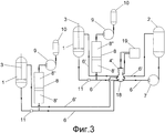
Фиг. 3 - общая схема установки с тремя емкостями для жидкого компонента, в две из которых вводят твердый наполнитель;FIG. 3 is a general installation diagram with three containers for a liquid component, in two of which a solid filler is introduced;
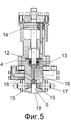
Фиг. 4 - схема смесительного узла, совмещенного со смесительной камерой при работе в режиме циркуляции;FIG. 4 is a diagram of a mixing unit combined with a mixing chamber when operating in a circulation mode;
Фиг. 5 - схема смесительного узла, совмещенного со смесительной камерой при работе в режиме заливки.FIG. 5 is a diagram of a mixing unit combined with a mixing chamber when operating in pour mode.
Лучшее осуществление изобретенияBEST MODE FOR CARRYING OUT THE INVENTION
Способ осуществляют на установке для производства высоконаполненных полиуретанов, которая содержит одну (Фиг. 1) или более емкостей (Фиг. 2, 3) для жидкого компонента, в который предварительно вводят твердый наполнитель. Установка содержит одну или более емкостей 2 для компонента без наполнителя. Емкость 1 снабжена мешалкой 3. Смесительный узел 4 со смесительной камерой 5 соединен с емкостями 1 и 2 для компонентов полиуретановой смеси трубопроводами 6 и 6′, которые могут быть трубами или рукавами. Трубопроводы 6 и 6′ в виде труб или рукавов являются гидравлическими.The method is carried out in a plant for the production of highly filled polyurethanes, which contains one (Fig. 1) or more containers (Fig. 2, 3) for a liquid component into which a solid filler is preliminarily introduced. The installation contains one or
Вход насоса высокого давления 7 соединен с выходом емкости 2 для компонентов без твердого наполнителя, а его выход - со смесительным узлом 4. Подача компонента с наполнителем в виде пульпы происходит с помощью гидравлического разделителя сред 8. Гидравлический разделитель сред 8 имеет рабочую полость 8′ и нагнетательную полость 8′′. Необходимое давление в гидравлическом разделителе сред 8 создают с помощью насоса высокого давления 9 посредством жидкой среды, хранящейся в емкости 10. Применяемый разделитель сред 8 может быть поршневым, баллонным, мембранным или сильфонным. Выход емкости 1 соединен с рабочей полостью 8′ гидравлического разделителя сред 8 и далее со смесительным узлом 4 или 4′ (Фиг. 3) Для исключения повышения давления в емкости 1 и для управления направлением потока трубопровод 6 снабжен клапанным устройством 11. Нагнетательная полость 8′′ разделителя сред соединена с выходом насоса высокого давления 9, а его вход соединен с емкостью 10.The inlet of the
Смесительный узел 4 (Фиг 4) содержит смесительную камеру 5, шток 12 с выполненным в нем перепускным каналом 13, поршень 14 гидравлического привода, каналы подачи 15 компонентов, каналы отвода 16 компонентов. Подача компонентов в направленных встречных потоках в смесительную камеру 5 осуществляется через форсунки 17. Форсунки 17 служат для регулирования давления перемешивания компонентов на каналах подачи 15 компонентов.The mixing unit 4 (FIG. 4) comprises a mixing
В нижней части смесительного узла 4 и 4′ (Фиг. 3) расположено выпускное отверстие 18 для выпуска приготовленной смеси в форму для теплоизоляции. Работу смесительного узла 4 и 4′ обеспечивает гидравлическая станция 19. Гидравлическая станция 19 создает высокое давление и с помощью клапанов осуществляет управление потоками гидравлической жидкости.At the bottom of the
Устройство смесительного узла 4 (Фиг. 1, 2, 4, 5) аналогично устройству смесительного узла 4′ (Фиг. 3). Отличаются указанные выше смесительные узлы тем, что смесительный узел 4 является двухкомпонентным, т.е. имеет возможность подачи в него двух компонентов целевой смеси. Смесительный узел 4′ является трехкомпонентным, обеспечивающим одновременную подачу трех компонентов полиуретановой смеси.The device of the mixing unit 4 (Fig. 1, 2, 4, 5) is similar to the device of the
Пример 1Example 1
В случае использования двух жидких компонентов, в один из которых добавляется твердый наполнитель (фиг. 1), работа технологической линии происходит следующим образом.In the case of using two liquid components, one of which is added solid filler (Fig. 1), the work of the production line is as follows.
Качество и количество твердого наполнителя выбирают в зависимости от требуемых свойств получаемого в результате осуществления способа продукта.The quality and quantity of solid filler is selected depending on the required properties of the product obtained as a result of the process.
Твердый наполнитель, в качестве которого используют окись титана в количестве 0,1% от общей расчетной массы получаемой полиуретановой смеси, вводят в емкость 1 для жидкого компонента, в которой установлен смесительный элемент 3. Производят перемешивание до однородной массы, получая однородную по составу пульпу. Для подачи компонентов из емкостей 1 и 2 в смесительный узел 4 используют трубопровод 6 в виде трубы или рукава высокого давления. Жидкий компонент без наполнителя из емкости 2 подают в смесительный узел 4 с помощью насоса высокого давления 7. Жидкий компонент с наполнителем подают в смесительный узел 4 с использованием гидравлического разделителя сред 8. Необходимое давление в гидравлическом разделителе сред 8 создают с помощью насоса высокого давления 9 посредством жидкой среды, хранящейся в емкости 10. Давление нагнетания передается пульпе посредством гидравлического разделителя сред 8.A solid filler, which is used as titanium oxide in an amount of 0.1% of the total calculated mass of the obtained polyurethane mixture, is introduced into the
Наполнение гидравлического разделителя сред 8 компонентом с наполнителем происходит посредством обратного хода насоса высокого давления 9.The filling of the hydraulic
Смесительный узел 4 является двухкомпонентным и работает в двух режимах: в режиме циркуляции и в режиме заливки. При нижнем положении штока 12 смесительная камера 5 смесительного узла 4 перекрыта и компоненты через форсунки 17 поступают в емкости 1 и 2 для хранения по трубопроводам 6′ - это режим циркуляции. Режим циркуляции используют для перемешивания компонентов, находящихся в трубах или рукавах трубопроводной системы 6′, а также для проверки и регулировки давления перемешивания компонентов, для прогрева смесительного узла 4, для опорожнения гидравлического разделителя сред 8. Для перевода в режим заливки гидравлический привод перемещает шток 12 вверх, перекрывая каналы отвода 16 компонентов и открывая смесительную камеру 5 смесительного устройства 4. Струи компонентов при противоструйной подаче перемешиваются и полученную композицию через выпускное отверстие 18 выводят из камеры в заливочную форму. При переводе в режим циркуляции шток вновь перемещается вниз, очищая и перекрывая смесительную камеру 5. Давление перемешивания компонентов на каналах подачи 15 компонентов регулируют при помощи форсунок 17.The
После приготовления расчетного количества смеси смесительный узел 4 переводят в режим циркуляции и установка работает в этом режиме до опорожнения полости 8′ гидравлического разделителя сред 8 от компонента с наполнителем.After preparing the calculated amount of the mixture, the mixing
Емкостей 1 и 2 для компонентов целевого продукта может быть несколько. В этом случае количество гидравлических разделителей сред 8 и количество насосов высокого давления 7 будет соответствовать количеству емкостей.
Пример 2Example 2
В случае использования двух жидких компонентов, в каждый из которых добавляют твердый наполнитель, установка содержит две емкости 1 с двумя разными компонентами полиуретановой композиции, в которые добавляют твердый наполнитель (Фиг 2). Емкости 1 снабжены мешалками 3 для приготовления из жидкого компонента и твердого наполнителя пульпы. Технологическая линия содержит два гидравлических разделителя сред 8, два клапанных устройства 11, два насоса высокого давления 9 и две емкости 10.In the case of using two liquid components, in each of which a solid filler is added, the installation contains two
В качестве твердого наполнителя используют один из таких ингредиентов, как песок кварцевый, песок строительный, магнезит, керамзит, керамические сферы, барит, резиновую крошку, другие подобные материалы или их смеси. Твердый наполнитель вводят в емкости 1 для жидких компонентов, в каждой из которых установлен смесительный элемент 3. Количество вводимого в каждую емкость твердого наполнителя определяют в зависимости от задаваемых качественных характеристик получаемого полиуретана. В данном случае общее количество твердого наполнителя в каждой емкости составляет 75% от массы целевого продукта. Общее количество твердого наполнителя, в качестве которого используют песок строительный, распределяют в две емкости 1 с жидкими компонентами. После получения в емкостях 1 пульпы ее подают в смесительный узел 4 с использованием гидравлических разделителей сред 8. Пульпа поступает по трубопроводу 6. Функционирование гидравлического разделителя и смесительного узла осуществляют в соответствии с описанием, приведенным в Примере 1.As a solid filler, one of such ingredients as quartz sand, building sand, magnesite, expanded clay, ceramic spheres, barite, crumb rubber, other similar materials or mixtures thereof is used. The solid filler is introduced into the
Пример 3Example 3
В случае использования трех емкостей для жидких компонентов, в две из которых добавляют твердый наполнитель (Фиг. 3), в технологическом процессе предусмотрены две емкости 1 с установленными мешалками 3, емкость 2, гидравлические разделители сред 8, насосы высокого давления 9, емкости 10 и клапанные устройства 11, обеспечивающие подачу пульпы с твердым наполнителем, количество которого может варьироваться в широких пределах и может составлять до 80% от суммарной массы получаемого продукта. В качестве твердого наполнителя используют песок строительный и резиновую крошку. Общее количество наполнителя составляет 40-50% от массы получаемого полиуретана. Производят перемешивание компонентов в емкостях 1 до получения однородной массы - пульпы. Для подачи компонентов из емкостей 1 и 2 в смесительный узел 4′ используют трубопровод 6 в виде труб или рукавов высокого давления. Жидкий компонент без наполнителя из емкости 2 подают в смесительный узел 4′ с помощью насоса высокого давления 7. Полученную пульпу с наполнителем подают в смесительный узел 4′ с использованием гидравлических разделителей сред 8. Для одновременной подачи всех компонентов используют трехкомпонентный смесительный узел 4′. Смесительный узел 4 может быть многокомпонентным, в зависимости от количества емкостей, участвующих одновременно в работе. Готовую смесь через выпускное отверстие 18 подают в формы для изоляции труб.In the case of using three containers for liquid components, two of which add solid filler (Fig. 3), two
Способ обеспечивает получение качественного тепло- звукоизоляционного материала, сокращая эксплуатационные расходы и исключая образование отходов. Снижая абразивный износ оборудования, позволяет уменьшить его габариты, в частности смесительного узла. Технологическая линия легко поддается автоматизации.The method provides high-quality heat and sound insulating material, reducing operating costs and eliminating waste generation. Reducing the abrasive wear of the equipment, allows to reduce its dimensions, in particular the mixing unit. The production line is easy to automate.
ИСТОЧНИКИ ИНФОРМАЦИИINFORMATION SOURCES
1. Патент 2257393 РФ, МПК C08G 18/08, C08J 5/10. Способ получения жесткого наполненного пенополиуретана / Золотухин В.А. - Заявка: 2003135801/04, заявл. 04.12.2003; опубл. 27.07.2005.1. RF patent 2257393,
2. Патент 2336283 РФ, МПК C08G 18/08, C08G 18/48, C08J 9/08. Способ получения огнестойкого пенополиуретана / Сучков В.П., Мольков А.А., Дергунов Ю.И.; ГОУ ВПО "Нижегородский государственный архитектурно-строительный университет". - Заявка 2006139455/04, заявл. 07.11.2006; опубл. 20.10.2008.2. RF patent 2336283,
3. Патент 94573 РФ, МПК C08G 18/08. Установка для изготовления наполненных полиуретанов / М.Е. Мишин, A.M. Мишина; Общество с ограниченной ответственностью научно-производственное предприятие "Пенополимер" (RU). - Заявка 2010105153/22, Заявл. 16.02.2010; опубл. 27.05.2010 г.3. RF patent 94573,
Claims (7)
Priority Applications (1)
| Application Number | Priority Date | Filing Date | Title |
|---|---|---|---|
| RU2014135242/04A RU2563243C1 (en) | 2014-08-28 | 2014-08-28 | Method to produce filled polyurethanes and installation for its realisation |
Applications Claiming Priority (1)
| Application Number | Priority Date | Filing Date | Title |
|---|---|---|---|
| RU2014135242/04A RU2563243C1 (en) | 2014-08-28 | 2014-08-28 | Method to produce filled polyurethanes and installation for its realisation |
Publications (1)
| Publication Number | Publication Date |
|---|---|
| RU2563243C1 true RU2563243C1 (en) | 2015-09-20 |
Family
ID=54147747
Family Applications (1)
| Application Number | Title | Priority Date | Filing Date |
|---|---|---|---|
| RU2014135242/04A RU2563243C1 (en) | 2014-08-28 | 2014-08-28 | Method to produce filled polyurethanes and installation for its realisation |
Country Status (1)
| Country | Link |
|---|---|
| RU (1) | RU2563243C1 (en) |
Cited By (2)
| Publication number | Priority date | Publication date | Assignee | Title |
|---|---|---|---|---|
| RU2694325C1 (en) * | 2018-06-25 | 2019-07-11 | федеральное государственное бюджетное образовательное учреждение высшего образования "Белгородский государственный технологический университет им. В.Г. Шухова" | Heat-insulating material based on foamed polyurethane |
| RU223274U1 (en) * | 2023-02-09 | 2024-02-12 | Общество с ограниченной ответственностью "Технологические машины" | MIXING UNIT OF INSTALLATION FOR PRODUCING POLYMER MATERIALS |
Citations (5)
| Publication number | Priority date | Publication date | Assignee | Title |
|---|---|---|---|---|
| RU4927U1 (en) * | 1997-02-21 | 1997-09-16 | Сергуненков Борис Борисович | INSTALLATION FOR PRODUCTION OF LIQUID-BASED MATERIALS |
| DE19706030A1 (en) * | 1997-02-17 | 1998-08-20 | Bayer Ag | Method and device for producing filler-containing polyurethanes |
| RU2257393C1 (en) * | 2003-12-04 | 2005-07-27 | Золотухин Виктор Антонович | Method of producing rigid filled polyurethane foam |
| RU2336283C2 (en) * | 2006-11-07 | 2008-10-20 | ГОУ ВПО "Нижегородский государственный архитектурно-строительный университет" | Method of production of fire resistant filled polyurethane |
| RU94573U1 (en) * | 2010-02-16 | 2010-05-27 | Общество с ограниченной ответственностью научно-производственное предприятие "Пенополимер" | PLANT FOR THE PRODUCTION OF FILLED FOAM POLYURETHANES |
-
2014
- 2014-08-28 RU RU2014135242/04A patent/RU2563243C1/en active IP Right Revival
Patent Citations (5)
| Publication number | Priority date | Publication date | Assignee | Title |
|---|---|---|---|---|
| DE19706030A1 (en) * | 1997-02-17 | 1998-08-20 | Bayer Ag | Method and device for producing filler-containing polyurethanes |
| RU4927U1 (en) * | 1997-02-21 | 1997-09-16 | Сергуненков Борис Борисович | INSTALLATION FOR PRODUCTION OF LIQUID-BASED MATERIALS |
| RU2257393C1 (en) * | 2003-12-04 | 2005-07-27 | Золотухин Виктор Антонович | Method of producing rigid filled polyurethane foam |
| RU2336283C2 (en) * | 2006-11-07 | 2008-10-20 | ГОУ ВПО "Нижегородский государственный архитектурно-строительный университет" | Method of production of fire resistant filled polyurethane |
| RU94573U1 (en) * | 2010-02-16 | 2010-05-27 | Общество с ограниченной ответственностью научно-производственное предприятие "Пенополимер" | PLANT FOR THE PRODUCTION OF FILLED FOAM POLYURETHANES |
Cited By (4)
| Publication number | Priority date | Publication date | Assignee | Title |
|---|---|---|---|---|
| RU2694325C1 (en) * | 2018-06-25 | 2019-07-11 | федеральное государственное бюджетное образовательное учреждение высшего образования "Белгородский государственный технологический университет им. В.Г. Шухова" | Heat-insulating material based on foamed polyurethane |
| RU223274U1 (en) * | 2023-02-09 | 2024-02-12 | Общество с ограниченной ответственностью "Технологические машины" | MIXING UNIT OF INSTALLATION FOR PRODUCING POLYMER MATERIALS |
| RU2832497C1 (en) * | 2024-04-01 | 2024-12-24 | Иван Александрович Королев | Method of mixing preliminarily prepared mixture of component with filler at low pressure in dynamic mixer |
| RU2849501C1 (en) * | 2025-04-07 | 2025-10-27 | Общество с ограниченной ответственностью "Технологические машины" | Method of mixing component with introduced filler, supplied under low pressure, in mixing chamber |
Similar Documents
| Publication | Publication Date | Title |
|---|---|---|
| JP7038103B2 (en) | Method for manufacturing fiber-reinforced cementum slurry using a multi-stage continuous mixer | |
| CN103857501B (en) | Solvent-free two-component spraying system and method | |
| JP7018051B2 (en) | Continuous mixer, and how to mix reinforced fiber and cement material | |
| US3625724A (en) | Cellular concrete and method for producing the same | |
| JP2010508180A (en) | Apparatus and method for wet mixing cement slurry for fiber reinforced structural cement panels | |
| US4366287A (en) | Glass fibre/synthetic resin paste or slurry | |
| JP2010508179A (en) | Method for wet mixing cement slurry for fiber reinforced structural cement panels | |
| AU2018314850B2 (en) | System for applying a building material | |
| JP2010508178A (en) | Process and apparatus for supplying cement slurry for fiber reinforced structural cement panels | |
| US4421797A (en) | Method and device for the dry-spray application of concrete to a substrate | |
| CN109496180A (en) | Head box and forming station for the production of fiber-reinforced cement plate | |
| US2887275A (en) | Apparatus for producing aerated cementitious material | |
| KR20200141462A (en) | Method for producing a lightweight gypsum composition having internally generated bubbles and products made therefrom | |
| RU2563243C1 (en) | Method to produce filled polyurethanes and installation for its realisation | |
| US3915438A (en) | Stream impingement mix head | |
| CN102837364B (en) | Group pouring device for foaming concrete slurry and working method thereof | |
| CN202826006U (en) | Group pouring device of foamed concrete sizing agent | |
| KR101614119B1 (en) | Manufacturing methode and manufacturing equipment for early strength concrete that have been undergoing process of mixing and dissipating air on common concrete | |
| JPS6023229B2 (en) | Spraying method | |
| KR102479552B1 (en) | Concrete with lightweight aggregate having lattice structure and method of manufacturing the same | |
| CN210098114U (en) | Inline gluing system | |
| RU94573U1 (en) | PLANT FOR THE PRODUCTION OF FILLED FOAM POLYURETHANES | |
| KR102344570B1 (en) | Foam insulation foaming device for field construction | |
| RU2778225C1 (en) | Method for obtaining a foam concrete mixture | |
| GB2164072A (en) | Composite concrete building panel |
Legal Events
| Date | Code | Title | Description |
|---|---|---|---|
| MM4A | The patent is invalid due to non-payment of fees |
Effective date: 20180829 |
|
| NF4A | Reinstatement of patent |
Effective date: 20210406 |