RU2561344C2 - Centrifugal pump - Google Patents
Centrifugal pump Download PDFInfo
- Publication number
- RU2561344C2 RU2561344C2 RU2013116378/06A RU2013116378A RU2561344C2 RU 2561344 C2 RU2561344 C2 RU 2561344C2 RU 2013116378/06 A RU2013116378/06 A RU 2013116378/06A RU 2013116378 A RU2013116378 A RU 2013116378A RU 2561344 C2 RU2561344 C2 RU 2561344C2
- Authority
- RU
- Russia
- Prior art keywords
- pump
- disk
- impeller
- separator
- ribs
- Prior art date
Links
Images

Classifications
-
- F—MECHANICAL ENGINEERING; LIGHTING; HEATING; WEAPONS; BLASTING
- F04—POSITIVE - DISPLACEMENT MACHINES FOR LIQUIDS; PUMPS FOR LIQUIDS OR ELASTIC FLUIDS
- F04D—NON-POSITIVE-DISPLACEMENT PUMPS
- F04D7/00—Pumps adapted for handling specific fluids, e.g. by selection of specific materials for pumps or pump parts
- F04D7/02—Pumps adapted for handling specific fluids, e.g. by selection of specific materials for pumps or pump parts of centrifugal type
- F04D7/04—Pumps adapted for handling specific fluids, e.g. by selection of specific materials for pumps or pump parts of centrifugal type the fluids being viscous or non-homogenous
- F04D7/045—Pumps adapted for handling specific fluids, e.g. by selection of specific materials for pumps or pump parts of centrifugal type the fluids being viscous or non-homogenous with means for comminuting, mixing stirring or otherwise treating
-
- F—MECHANICAL ENGINEERING; LIGHTING; HEATING; WEAPONS; BLASTING
- F04—POSITIVE - DISPLACEMENT MACHINES FOR LIQUIDS; PUMPS FOR LIQUIDS OR ELASTIC FLUIDS
- F04D—NON-POSITIVE-DISPLACEMENT PUMPS
- F04D9/00—Priming; Preventing vapour lock
- F04D9/001—Preventing vapour lock
- F04D9/002—Preventing vapour lock by means in the very pump
- F04D9/003—Preventing vapour lock by means in the very pump separating and removing the vapour
Landscapes
- Engineering & Computer Science (AREA)
- Mechanical Engineering (AREA)
- General Engineering & Computer Science (AREA)
- Structures Of Non-Positive Displacement Pumps (AREA)
- Paper (AREA)
Abstract
Description
Область техникиTechnical field
Изобретение относится к центробежному насосу для подачи газосодержащей суспензии волокнистого материала, включающему рабочее колесо, по меньшей мере, с одним отверстием в несущей пластине и ребрами на ее задней стороне. Предусмотрено сепараторное устройство, включающее корпус сепаратора и диск, вращающийся вместе с валом насоса. Сепараторное устройство в корпусе насоса расположено, если смотреть на рабочее колесо насоса в осевом направлении, с задней стороны рабочего колеса вплотную к нему. Корпус сепаратора включает камеру газосборника с газоотводным трубопроводом. Диск, вращающийся вместе с валом насоса, имеет сплошную поверхность без отверстий.The invention relates to a centrifugal pump for supplying a gas-containing suspension of fibrous material, comprising an impeller with at least one hole in the carrier plate and ribs on its rear side. A separator device is provided, including a separator housing and a disk rotating together with the pump shaft. The separator device in the pump housing is located, if you look at the pump impeller in the axial direction, from the back of the impeller close to it. The separator body includes a gas collector chamber with a gas outlet pipe. The disk rotating with the pump shaft has a continuous surface without holes.
Уровень техникиState of the art
Современные насосы для перекачивания суспензий волокнистого материала средней концентрации требуют для обеспечения возможности перекачки отделения воздуха от целлюлозы. Это достигается тем, что вначале под действием сдвиговых сил происходит ожижение целлюлозы (с помощью размещенных на валу насоса «смесителей или ожижителей» - или с помощью внешнего устройства («кондиционера»)), при этом воздух отделяется от материала. Этот воздух затем выводится из насоса с помощью вакуумного насоса или без такового. В зависимости от консистенции среды и/или содержания воздуха и расхода насоса, происходят потери волокна в трубопроводе дегазации. Чтобы преодолеть этот недостаток или, по меньшей мере, уменьшить его влияние, применяются сравнительно дорогие системы управления, цель которых - снизить потери волокна. Такого рода система известна, например, из документа US 5087171. Далее, в документе EP 1736218 A1 описано газоотделительное устройство с ротором. Здесь также имеет место большая потеря волокна при его транспортировке в камеру дегазации. И чтобы ограничить потери волокна, здесь также приходится идти на компромисс, приводящий к снижению производительности насоса. Эти известные системы требуют больших производственных затрат, кроме того, велики издержки переналадки контуров регулирования, которые на всех установках должны быть согласованы для того или иного типа материала. Далее, существующие системы недостаточно надежны для полного устранения потерь волокна. Потери волокна, наряду с потерями целлюлозы, могут также приводить к нарушениям устойчивости работы насоса.Modern pumps for pumping suspensions of fibrous material of medium concentration require to allow the separation of air from the pulp to be pumped. This is achieved by the fact that initially, under the action of shear forces, cellulose is liquefied (using “mixers or liquefiers” placed on the pump shaft — or using an external device (“air conditioner”)), while air is separated from the material. This air is then removed from the pump with or without a vacuum pump. Depending on the consistency of the medium and / or the air content and the flow rate of the pump, fiber loss occurs in the degassing pipe. To overcome this drawback, or at least reduce its impact, relatively expensive control systems are used, the purpose of which is to reduce fiber loss. A system of this kind is known, for example, from US Pat. No. 5,087,171. Further, a gas separation device with a rotor is described in EP 1736218 A1. There is also a large loss of fiber during its transportation to the degassing chamber. And in order to limit fiber loss, one also has to compromise, leading to lower pump performance. These well-known systems require large production costs, in addition, there are high costs of readjusting control loops, which at all installations must be coordinated for a particular type of material. Further, existing systems are not reliable enough to completely eliminate fiber loss. Loss of fiber, along with loss of cellulose, can also lead to impaired stability of the pump.
Раскрытие изобретенияDisclosure of invention
Задача изобретения заключается в том, чтобы устранить этот недостаток.The objective of the invention is to eliminate this disadvantage.
Таким образом, согласно изобретению указанная стенка выполнена в виде неподвижного диска и снабжена ребрами (направляющими лопатками), причем неподвижный диск со стороны, обращенной к рабочему колесу насоса, может иметь гладкую поверхность, а ребра могут располагаться на противолежащей стороне. Ребра или направляющие лопатки могут располагаться радиально или под любым углом и могут быть выполнены прямыми или изогнутыми. Это, вместе со сплошной поверхностью вращающегося с валом диска, дает то преимущество, что потерь материала практически уже нет и насос работает устойчиво. При этом волокнистый материал, выдавленный в направлении зоны дегазации, рабочим колесом сепаратора подается обратно в насос, а воздух может выходить из насоса против перекачивающей подачи сепаратора.Thus, according to the invention, said wall is made in the form of a fixed disk and provided with ribs (guide vanes), the fixed disk on the side facing the impeller of the pump can have a smooth surface, and the ribs can be located on the opposite side. The ribs or guide vanes can be located radially or at any angle and can be made straight or curved. This, together with the solid surface of the disk rotating with the shaft, gives the advantage that there is practically no material loss and the pump works stably. In this case, the fibrous material squeezed out in the direction of the degassing zone is fed back to the pump by the separator impeller, and air can exit the pump against the pumping supply of the separator.
Один из предпочтительных вариантов изобретения отличается тем, что вращающийся вместе с валом насоса диск снабжен ребрами (лопатками), причем вращающийся вместе с валом насоса диск на стороне, обращенной к неподвижному диску, может иметь гладкую поверхность, а ребра могут располагаться на противолежащей стороне. И здесь ребра или направляющие лопатки также могут располагаться радиально или под любым углом и могут быть выполнены прямыми или изогнутыми. Этим достигается дальнейшее снижение потерь материала.One of the preferred embodiments of the invention is characterized in that the disk rotating together with the pump shaft is provided with ribs (vanes), and the disk rotating together with the pump shaft on the side facing the stationary disk can have a smooth surface, and the ribs can be located on the opposite side. And here, the ribs or guide vanes can also be located radially or at any angle and can be made straight or curved. This achieves a further reduction in material loss.
Один из вариантов изобретения отличается тем, что в корпусе сепаратора предусмотрено отверстие для промывной воды, соединяющееся с каналом, образованным ребрами вращающегося вместе с валом диска (рабочего колеса сепаратора), и предотвращающее забивание сепараторного устройства.One of the variants of the invention is characterized in that a hole for washing water is provided in the separator housing, which connects to the channel formed by the ribs of the disk (separator impeller) rotating together with the shaft and preventing the separator device from clogging.
Если перед рабочим колесом насоса смонтирован ожижитель, который может быть выполнен как связанный с валом насоса ротор или как отделенный от вала насоса ротор, то суспензия волокнистого материала ожижается просто и воздух отделяется от материала. Волокнистый материал поступает в рабочее колесо насоса, где основная масса целлюлозы закачивается в спиральный корпус. При этом часть взвеси волокнистого материала (суспензии волокнистого материала с воздухом), которая продавливается сквозь дегазационные отверстия в рабочем колесе насоса, а также приносится возвратными потоками в заднюю зону рабочего колеса насоса, попадает в дегазационную или сепараторную камеру.If a liquefier is mounted in front of the impeller of the pump, which can be made as a rotor connected to the pump shaft or as a rotor separated from the pump shaft, the suspension of fibrous material is simply liquefied and air is separated from the material. The fibrous material enters the impeller of the pump, where the bulk of the pulp is pumped into a spiral casing. In this case, part of the suspension of fibrous material (suspension of fibrous material with air), which is forced through the degassing holes in the impeller of the pump, and also brought back by flows into the rear zone of the impeller of the pump, enters the degassing or separator chamber.
Краткое описание чертежейBrief Description of the Drawings
Настоящее изобретение описывается на примере со ссылкой на чертежи:The present invention is described by way of example with reference to the drawings:
Фиг.1 - система подачи газосодержащей суспензии в уровне техники,Figure 1 - system for supplying a gas-containing suspension in the prior art,
Фиг.2 - вариант центробежного насоса согласно изобретению,Figure 2 is a variant of a centrifugal pump according to the invention,
Фиг.3 - разрез по III-III Фиг.2.Figure 3 is a section along III-III of Figure 2.
Осуществление изобретенияThe implementation of the invention
На Фиг.1 показана система подачи газосодержащей суспензии с устройством дегазации согласно уровню техники. Центробежный насос 1 здесь смонтирован в нижней части стояка 2, находящегося под большим резервуаром 3, например под отбельной башней или аналогичным узлом. Насос 1 включает выпускной трубопровод 4 для перекачиваемой среды, например суспензии волокнистого материала, а также включает на входе ротор 5, который целиком находится в стояке 2 и, взаимодействуя со стенкой стояка 2, должен вызывать турбулентность, приводящую к ожижению суспензии волокнистого материала. В выпускном трубопроводе 4 располагается регулировочный вентиль 6, соединенный с управляющим устройством 7.Figure 1 shows a gas suspension system with a degassing device according to the prior art. The centrifugal pump 1 is mounted here in the lower part of the
Далее, насос 1 включает газоотводный трубопровод 8, в котором располагается регулировочный вентиль 9 и вакуумный насос 10. Управляющее устройство 7 управляет количеством материала в выпускном трубопроводе 4 с помощью регулировочного вентиля 6, а также, в частности, регулировочного вентиля 9 в газоотводном трубопроводе 8. Если уровень суспензии в резервуаре 3 и стояке 2, замеренный датчиком давления 11 у нижнего конца стояка 2, слишком высок и, в связи с этим, есть опасность попадания суспензии в газоотводный трубопровод 8, управляющее устройство 7 закрывает регулировочный вентиль 9. По существу, эта система позволяет обеспечить достаточное отделение газа при запуске и выключении системы.Further, the pump 1 includes a
На Фиг.2 показан разрез соответствующего настоящему изобретению центробежного насоса 1, включающего рабочее колесо 12 насоса и интегрированный с ним ожижитель 13. В рабочем колесе 12 вблизи оси 14 имеются отверстия 15 для отвода газа, собирающегося в ожижителе. На задней стороне рабочего колеса 12 насоса расположены ребра 16. Вследствие вращения рабочего колеса 12 ребра 16, находясь в газожидкостном потоке, проходящем через отверстия 15, подают волокна и жидкость обратно в насосную камеру. Далее, к рабочему колесу насоса примыкает сепараторное устройство 17. Последнее включает неподвижную статорную пластину 18 с неподвижными лопатками или ребрами 19, которая со стороны, обращенной к рабочему колесу 12 насоса, имеет гладкую поверхность 20, причем одна или несколько направляющих лопаток или ребер 19 расположены на противолежащей стороне, могут располагаться радиально или под любым углом и могут быть выполнены прямыми или изогнутыми. Кроме того, внутренний диаметр статорной пластины 18 больше внутреннего диаметра ребер 19 неподвижного диска 18 в этой зоне, чтобы обеспечить свободный проход суспензии воздуха/волокнистого материала. Это свободное пространство - почти до наружного диаметра вала насоса - может быть также облопачено лопатками статорной пластины 18. Рядом со статорной пластиной 18 посажен жестко связанный с валом насоса и вращающийся с его скоростью диск 22, играющий роль вращающегося рабочего колеса 22 сепаратора. Это рабочее колесо 22 сепаратора со стороны, обращенной к статорной пластине 18, имеет гладкую поверхность 23, а со стороны, обращенной от статорной пластины 18, включает одну или несколько лопаток или ребер 24. Диаметр этого вращающегося диска 22 меньше внутреннего диаметра корпуса 25 сепаратора, и между наружной периферией диска и корпусом 25 сепаратора образуется зазор 26, обеспечивающий проход воздушного потока, а также и волокон. Этот вращающийся диск 22 имеет сплошную поверхность без отверстий. Увеличение давления внутри сепаратора возможно только при наличии поверхности без отверстий. Тем самым в очень значительной мере предотвращается выход волокнистого материала в камеру дегазации, и воздух может выходить из насоса против перекачивающей подачи сепаратора. Во избежание забивания сепараторного устройства 17 сквозь отверстие 27 в насос может подаваться промывная вода.Figure 2 shows a section according to the present invention of a centrifugal pump 1, comprising a pump impeller 12 and an integrated fluidizer 13. In the impeller 12 near the axis 14 there are openings 15 for exhausting gas collected in the fluidizer. On the rear side of the impeller 12 of the pump are ribs 16. Due to the rotation of the impeller 12 of the ribs 16, while in the gas-liquid flow passing through the holes 15, fibers and liquid are fed back into the pump chamber. Further, a separator device 17 is adjacent to the pump impeller 17. The latter includes a fixed stator plate 18 with fixed vanes or
В центробежных насосах для газосодержащих суспензий, например в насосах для суспензий средней концентрации, в зависимости от расхода и консистенции среды, волокнистый материал вдавливается сквозь отверстия 15 в камеру дегазации или, в данном случае, в сепараторное устройство 17. Этот волокнистый материал с помощью лопаток 24 подается рабочим колесом 22 сепаратора обратно в насос. В условиях работы, при которых в сепараторное устройство 17 или в камеру дегазации не вдавливается или вдавливается мало волокнистого материала, сквозь сепараторное устройство 17 продавливается, в зависимости от количества отсепарированного воздуха, больше или меньше воздуха. Этот воздух через канал 28, находящийся со стороны, обращенной от рабочего колеса 22 сепаратора, выводится из насоса с помощью вакуумного насоса или без такового. Таким образом, через сепараторное устройство 17 согласно настоящему изобретению происходит постоянная возвратная перекачка волокон, при этом она не мешает выходящему воздушному потоку. А благодаря тому, что рабочее колесо 22 сепаратора имеет сплошную поверхность без отверстий, предотвращается выход волокон.In centrifugal pumps for gas-containing suspensions, for example in pumps for suspensions of medium concentration, depending on the flow rate and consistency of the medium, the fibrous material is pressed through the openings 15 into the degassing chamber or, in this case, into the separator device 17. This fibrous
Корпус 25 сепаратора с валом 21 насоса образует камеру газосборника 31 и содержит газоотводное отверстие (28) и подвод 27 промывной воды. Отделенный газ, в частности отделенный воздух, течет от задней стороны рабочего колеса 12 насоса через каналы, образованные ребрами 19 неподвижного диска 18, затем через зазор 26 и каналы, образованные ребрами 24 вращающегося диска 22, попадает в камеру газосборника 31 и оттуда через газоотводный трубопровод с дополнительным вакуумным насосом или без оного выводится из центробежного насоса 1.The separator housing 25 with the
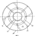
На Фиг.3 показан разрез соответствующего настоящему изобретению центробежного насоса по III-III Фиг.2. На разрезе можно видеть вал 21, а также вращающийся диск 22 с ребрами 24, которые здесь выполнены прямыми. Далее, видны ребра 19 неподвижного диска 18, которые здесь, для примера, показаны изогнутыми. Но и ребра 19 неподвижного диска 18, и ребра 24 вращающегося диска 22 могут быть выполнены как прямыми, так и изогнутыми. Далее, на Фиг.3 виден зазор 26 между вращающимся диском 22 и корпусом 25. Видно также находящееся между неподвижным диском 18 и валом 21 насоса кольцевое пространство 29, через которое газожидкостная смесь поступает в сепараторное устройство 17.Figure 3 shows a section according to the present invention of the centrifugal pump according to III-III of Figure 2. In the section, you can see the
При отсутствии сепараторного устройства всегда приходится идти на компромисс в отношении, с одной стороны, потерь волокна, а с другой, устойчивости работы и производительности насоса. Благодаря использованию сепараторного устройства согласно настоящему изобретению можно развязать потери волокна и устойчивость работы или производительность насоса.In the absence of a separator device, one always has to compromise with respect to, on the one hand, fiber loss, and, on the other hand, stability of operation and pump performance. Through the use of the separator device according to the present invention, the fiber loss and the operation stability or pump performance can be decoupled.
Claims (8)
Applications Claiming Priority (3)
| Application Number | Priority Date | Filing Date | Title |
|---|---|---|---|
| ATA1613/2010A AT510538B1 (en) | 2010-09-27 | 2010-09-27 | CENTRIFUGAL PUMP |
| ATA1613/2010 | 2010-09-27 | ||
| PCT/AT2011/000391 WO2012040752A1 (en) | 2010-09-27 | 2011-09-23 | Centrifugal pump |
Publications (2)
| Publication Number | Publication Date |
|---|---|
| RU2013116378A RU2013116378A (en) | 2014-11-10 |
| RU2561344C2 true RU2561344C2 (en) | 2015-08-27 |
Family
ID=44913127
Family Applications (1)
| Application Number | Title | Priority Date | Filing Date |
|---|---|---|---|
| RU2013116378/06A RU2561344C2 (en) | 2010-09-27 | 2011-09-23 | Centrifugal pump |
Country Status (9)
| Country | Link |
|---|---|
| US (1) | US9784275B2 (en) |
| EP (1) | EP2622225B1 (en) |
| CN (1) | CN103124852B (en) |
| AT (1) | AT510538B1 (en) |
| BR (1) | BR112013007344B1 (en) |
| ES (1) | ES2579005T3 (en) |
| PT (1) | PT2622225T (en) |
| RU (1) | RU2561344C2 (en) |
| WO (1) | WO2012040752A1 (en) |
Cited By (1)
| Publication number | Priority date | Publication date | Assignee | Title |
|---|---|---|---|---|
| RU2795774C2 (en) * | 2018-11-30 | 2023-05-11 | Андритц Ой | Device and method for pump degassing |
Families Citing this family (10)
| Publication number | Priority date | Publication date | Assignee | Title |
|---|---|---|---|---|
| AT510538B1 (en) | 2010-09-27 | 2013-02-15 | Andritz Ag Maschf | CENTRIFUGAL PUMP |
| JP6088918B2 (en) * | 2013-06-28 | 2017-03-01 | 株式会社丸八ポンプ製作所 | Centrifugal pump |
| CN104373362A (en) * | 2013-08-12 | 2015-02-25 | 苏州维艾普新材料股份有限公司 | Planar draw-off equipment for materials |
| EP2894343B2 (en) | 2014-01-12 | 2021-09-01 | Alfa Laval Corporate AB | Self-priming centrifugal pump |
| DK2894342T3 (en) | 2014-01-12 | 2017-04-03 | Alfa Laval Corp Ab | SELF-TILTING CENTRIFUGAL PUMP |
| CA2957279C (en) * | 2014-08-06 | 2020-08-04 | Flow Control Llc. | Impeller with axially curving vane extensions to prevent airlock |
| US20190023411A1 (en) * | 2017-07-24 | 2019-01-24 | Hamilton Sundstrand Corporation | Hydrocarbon fuel system |
| KR102495740B1 (en) * | 2018-03-14 | 2023-02-06 | 한화파워시스템 주식회사 | Impeller |
| CN109340122A (en) * | 2018-09-28 | 2019-02-15 | 佛山市金诺凯机械设备有限公司 | A kind of high-pressure pump of Production of Ceramics |
| FI129759B (en) * | 2018-11-30 | 2022-08-15 | Andritz Oy | Arrangement and method for degassing a pump |
Citations (5)
| Publication number | Priority date | Publication date | Assignee | Title |
|---|---|---|---|---|
| SU558691A1 (en) * | 1975-11-27 | 1977-05-25 | Всесоюзный Научно-Исследовательский Биотехнический Институт | Separation device |
| US4936744A (en) * | 1989-07-25 | 1990-06-26 | Goulds Pumps, Incorporated | Centrifugal pump |
| US5087171A (en) * | 1989-07-25 | 1992-02-11 | Goulds Pumps, Incorporated | Paper pulp centrifugal pump with gas separation |
| US5266160A (en) * | 1989-05-10 | 1993-11-30 | Kamyr, Inc. | Method of an apparatus for treating pulp |
| EP1736218A1 (en) * | 2005-06-22 | 2006-12-27 | Sulzer Pumpen Ag | A gas separation apparatus, a front wall and a separation rotor thereof |
Family Cites Families (9)
| Publication number | Priority date | Publication date | Assignee | Title |
|---|---|---|---|---|
| US5116198A (en) * | 1990-09-07 | 1992-05-26 | Ahlstrom Corporation | Centrifugal pumping apparatus |
| US5151010A (en) * | 1990-09-07 | 1992-09-29 | A. Ahlstrom Corporation | Combined centrifugal and vacuum pump |
| US5114310A (en) * | 1990-09-07 | 1992-05-19 | A. Ahlstrom Corporation | Centrifugal pump with sealing means |
| FI97024C (en) * | 1991-07-15 | 1996-10-10 | Ahlstroem Oy | Method and apparatus for separating gas from a gas-containing material |
| SE502127C2 (en) * | 1993-12-01 | 1995-08-28 | Kvaerner Pulping Tech | Device at a vacuum pump for venting the suspension pump |
| SE510031C2 (en) * | 1998-06-17 | 1999-04-12 | Sunds Defibrator Ind Ab | Centrifugal pump for pumping a pulp suspension |
| FI111023B (en) * | 1998-12-30 | 2003-05-15 | Sulzer Pumpen Ag | Method and apparatus for pumping material and rotor used in connection with the apparatus |
| FI20050674L (en) | 2005-06-22 | 2006-12-23 | Sulzer Pumpen Ag | Centrifugal pump its rear wall and separator wheel |
| AT510538B1 (en) | 2010-09-27 | 2013-02-15 | Andritz Ag Maschf | CENTRIFUGAL PUMP |
-
2010
- 2010-09-27 AT ATA1613/2010A patent/AT510538B1/en active
-
2011
- 2011-09-23 EP EP11779548.4A patent/EP2622225B1/en active Active
- 2011-09-23 CN CN201180046591.0A patent/CN103124852B/en active Active
- 2011-09-23 PT PT117795484T patent/PT2622225T/en unknown
- 2011-09-23 ES ES11779548.4T patent/ES2579005T3/en active Active
- 2011-09-23 RU RU2013116378/06A patent/RU2561344C2/en active
- 2011-09-23 WO PCT/AT2011/000391 patent/WO2012040752A1/en active Application Filing
- 2011-09-23 BR BR112013007344-6A patent/BR112013007344B1/en active IP Right Grant
- 2011-09-23 US US13/876,383 patent/US9784275B2/en active Active
Patent Citations (5)
| Publication number | Priority date | Publication date | Assignee | Title |
|---|---|---|---|---|
| SU558691A1 (en) * | 1975-11-27 | 1977-05-25 | Всесоюзный Научно-Исследовательский Биотехнический Институт | Separation device |
| US5266160A (en) * | 1989-05-10 | 1993-11-30 | Kamyr, Inc. | Method of an apparatus for treating pulp |
| US4936744A (en) * | 1989-07-25 | 1990-06-26 | Goulds Pumps, Incorporated | Centrifugal pump |
| US5087171A (en) * | 1989-07-25 | 1992-02-11 | Goulds Pumps, Incorporated | Paper pulp centrifugal pump with gas separation |
| EP1736218A1 (en) * | 2005-06-22 | 2006-12-27 | Sulzer Pumpen Ag | A gas separation apparatus, a front wall and a separation rotor thereof |
Cited By (1)
| Publication number | Priority date | Publication date | Assignee | Title |
|---|---|---|---|---|
| RU2795774C2 (en) * | 2018-11-30 | 2023-05-11 | Андритц Ой | Device and method for pump degassing |
Also Published As
| Publication number | Publication date |
|---|---|
| BR112013007344A2 (en) | 2016-07-05 |
| WO2012040752A1 (en) | 2012-04-05 |
| EP2622225A1 (en) | 2013-08-07 |
| AT510538B1 (en) | 2013-02-15 |
| US20140023485A1 (en) | 2014-01-23 |
| RU2013116378A (en) | 2014-11-10 |
| PT2622225T (en) | 2016-07-12 |
| AT510538A1 (en) | 2012-04-15 |
| CN103124852A (en) | 2013-05-29 |
| CN103124852B (en) | 2016-09-21 |
| ES2579005T3 (en) | 2016-08-03 |
| BR112013007344B1 (en) | 2020-12-08 |
| EP2622225B1 (en) | 2016-04-06 |
| US9784275B2 (en) | 2017-10-10 |
Similar Documents
| Publication | Publication Date | Title |
|---|---|---|
| RU2561344C2 (en) | Centrifugal pump | |
| FI86333C (en) | FOERFARANDE OCH ANORDNING FOER SEPARERING AV GAS MED PUMPEN UR MEDIET SOM SKALL PUMPAS. | |
| CN107429698B (en) | Impeller for centrifugal headbox feed pump | |
| RU2392499C2 (en) | Centrifugal pump and its impeller | |
| CA1158570A (en) | Method and apparatus for separating a gas from a fibre suspension | |
| US5078573A (en) | Liquid ring pump having tapered blades and housing | |
| JP4724610B2 (en) | Gas separation device, its front wall and separation rotor | |
| WO2016088725A1 (en) | Gas-liquid separation device | |
| US3944406A (en) | Centrifugal pump for pumping liquids with heavy gas content | |
| US5711789A (en) | Apparatus for pumping gas-containing fiber suspensions | |
| JP2014034885A (en) | Submersible motor pump | |
| WO2014122819A1 (en) | Centrifugal compressor | |
| CN104763641B (en) | A kind of rotational flow self-priming pump | |
| JP2001517284A (en) | Centrifugal liquid pump with internal gas injector | |
| KR101393054B1 (en) | Adapter for preventing cavitaion and centrifugal pump having adapter | |
| US20090213686A1 (en) | Method and Apparatus for Feeding Gaseous or Liquid Fluid into a Medium | |
| CN208203659U (en) | A kind of pump housing of water pump | |
| JP2007177737A (en) | Centrifugal compressor | |
| JP2019070333A (en) | Submerged pump | |
| CN109695574A (en) | A kind of vertical double suction non-sealing self-sucking pump | |
| CN103994098A (en) | Novel double-suction vortex pump | |
| KR0137653B1 (en) | Jet pump with guide | |
| JPH05321867A (en) | Complex impeller formed by integrating mixed flow blade and centrifugal blade together | |
| JP2011007091A (en) | Pump | |
| RU2239725C2 (en) | Centrifugal pump |