RU2559996C2 - Household cooking stove - Google Patents
Household cooking stove Download PDFInfo
- Publication number
- RU2559996C2 RU2559996C2 RU2012148069/03A RU2012148069A RU2559996C2 RU 2559996 C2 RU2559996 C2 RU 2559996C2 RU 2012148069/03 A RU2012148069/03 A RU 2012148069/03A RU 2012148069 A RU2012148069 A RU 2012148069A RU 2559996 C2 RU2559996 C2 RU 2559996C2
- Authority
- RU
- Russia
- Prior art keywords
- covering element
- front component
- door
- coupling means
- play
- Prior art date
Links
Images


Classifications
-
- F—MECHANICAL ENGINEERING; LIGHTING; HEATING; WEAPONS; BLASTING
- F24—HEATING; RANGES; VENTILATING
- F24C—DOMESTIC STOVES OR RANGES ; DETAILS OF DOMESTIC STOVES OR RANGES, OF GENERAL APPLICATION
- F24C15/00—Details
- F24C15/08—Foundations or supports plates; Legs or pillars; Casings; Wheels
-
- F—MECHANICAL ENGINEERING; LIGHTING; HEATING; WEAPONS; BLASTING
- F24—HEATING; RANGES; VENTILATING
- F24C—DOMESTIC STOVES OR RANGES ; DETAILS OF DOMESTIC STOVES OR RANGES, OF GENERAL APPLICATION
- F24C7/00—Stoves or ranges heated by electric energy
- F24C7/08—Arrangement or mounting of control or safety devices
- F24C7/082—Arrangement or mounting of control or safety devices on ranges, e.g. control panels, illumination
Abstract
Description
Область техники, к которой относится изобретениеFIELD OF THE INVENTION
Настоящее изобретение относится к бытовой кухонной плите, в частности печи, имеющей признаки, раскрытые в ограничительной части п. 1 формулы изобретения. Аналогично изобретение относится к способу сборки передних компонентов бытовой кухонной плиты, в частности печи, согласно ограничительной части пункта 12 формулы изобретения.The present invention relates to a domestic cooker, in particular a stove, having the features disclosed in the restrictive part of claim 1. Similarly, the invention relates to a method for assembling the front components of a domestic cooker, in particular a stove, according to the preamble of
Уровень техники изобретенияBACKGROUND OF THE INVENTION
Бытовые кухонные плиты, имеющие готовочную камеру, обычно содержат неподвижную конструкцию, содержащую муфель, который закрывается спереди посредством дверцы. Дверца шарнирно соединена в ее нижней области с передней частью неподвижной конструкции бытовой плиты так, что она может поворачиваться вокруг горизонтальной оси.Domestic cookers having a cooking chamber typically comprise a fixed structure comprising a muffle, which is closed in front by a door. The door is pivotally connected in its lower region to the front of the fixed structure of the household stove so that it can rotate around a horizontal axis.
В этих плитах передняя часть плиты обычно также содержит пользовательский интерфейс или панель управления. Эта панель управления в общем размещена выше дверцы и включает покрывающий элемент, в общем в форме пластины, в которой представлены средства управления печью, например клавиши, нажимные кнопки, круглые ручки и возможные средства визуальной индикации, например, аварийные лампы или дисплеи. Вышеуказанный покрывающий элемент несет в себе подходящие индикации, например, в форме сериграфов, для средств управления и/или индикации. Часто этот покрывающий элемент изготовлен из пластикового материала, с возможным дополнительным внешним передним покрытием, изготовленным из стекла. Покрывающий элемент обычно имеет отверстия или сквозные гнезда для прохождения валов для приведения в действие средств управления (когда они содержат поворотные переключатели или потенциометры) или для крепления средств управления (таких как клавиши и нажимные кнопки), а также возможных средств индикации (таких как аварийные лампы и дисплеи).In these plates, the front of the plate usually also contains a user interface or control panel. This control panel is generally located above the door and includes a cover element, generally in the form of a plate, in which the furnace controls, for example keys, push buttons, round handles and possible visual indicators, for example emergency lamps or displays, are presented. The aforementioned covering element carries suitable indications, for example, in the form of serigraphs, for controls and / or indications. Often this covering element is made of plastic material, with a possible additional outer front coating made of glass. The cover element typically has openings or through sockets for passing shafts to actuate controls (when they include rotary switches or potentiometers) or to attach controls (such as keys and push buttons) as well as possible indicators (such as emergency lights and displays).
В этих плитах между нижним краем покрывающего элемента и верхним краем дверцы обеспечен промежуток такой высоты, чтобы обеспечивать свободное угловое перемещение дверцы без какого-либо сталкивания с покрывающим элементом. В некоторых решениях по меньшей мере часть этого промежутка также используется в качестве выпускного отверстия для отходящих газов или испарений, вытесняемых готовочной камерой, возможно используя наличие вентилятора снаружи муфеля.In these plates, a gap of such a height is provided between the lower edge of the covering element and the upper edge of the door to allow free angular movement of the door without any collision with the covering element. In some solutions, at least a portion of this gap is also used as an outlet for exhaust gases or vapors displaced by the cooking chamber, possibly using a fan outside the muffle.
Для крепления вышеприведенных передних компонентов плиты дверца в общем шарнирно соединяется с неподвижной конструкцией, после чего устанавливается покрывающий элемент, а после этого средства управления и/или индикации уже устанавливаются/ется на этой конструкции или на указанном покрывающем элементе.To fasten the above-mentioned front components of the plate, the door is generally pivotally connected to the fixed structure, after which a cover element is installed, and after that the control and / or indication means are already installed / installed on this structure or on the specified cover element.
Крепление покрывающего элемента к конструкции печи обычно обеспечивается с помощью резьбовых элементов, в общем представленных шпильками, закрепленными относительно квадратных брусков, которые приклеиваются к задней части покрывающего элемента. Для указанного крепления на конструкции печи в ее переднем компоненте обеспечены сквозные отверстия, через которые шпильки имеют возможность проходить. Далее крепление завершается посредством гаек, которые навинчиваются на стержни шпилек; таким образом, передний компонент печи остается установленным между гайками и покрывающим элементом.The fastening of the coating element to the furnace structure is usually achieved by means of threaded elements, generally represented by studs fixed relative to square bars that adhere to the rear of the coating element. For the indicated fastening on the furnace structure, through holes are provided in its front component through which the studs are able to pass. Further, the fastening is completed by means of nuts that are screwed onto the stud rods; thus, the front component of the furnace remains installed between the nuts and the covering element.
Для того чтобы гарантировать хороший эстетичный и функциональный эффект, нижний край покрывающего элемента и верхний край дверцы должны быть установлены выровненными и параллельными друг другу. Также боковые края покрывающего элемента и дверцы должны быть установлены идеально выровненными. Для обеспечения удобной вставки шпилек в отверстия, обеспеченные на переднем компоненте конструкции, последние имеют диаметр, незначительно больший диаметра стержня шпилек, с положением и размером отверстий и шпилек, а также положением соответствующих принимающих гнезд на покрывающем элементе, которые точно устанавливаются на фазе проектирования.In order to guarantee a good aesthetic and functional effect, the lower edge of the covering element and the upper edge of the door must be aligned and parallel to each other. Also, the lateral edges of the covering element and the doors must be perfectly aligned. To ensure convenient insertion of the studs into the holes provided on the front component of the structure, the latter have a diameter slightly larger than the diameter of the stud shaft, with the position and size of the holes and studs, as well as the position of the corresponding receiving sockets on the covering element, which are precisely installed during the design phase.
Случилось так, что из-за производственных или сборочных допусков переднего элемента конструкции дверцы и покрывающего элемента может возникать отклонение между рассматриваемыми частями, в частности между лицевыми краями покрывающего элемента и дверцы и между боковыми краями покрывающего элемента и дверцы. Эти отклонения, хоть и в минимальной степени, приводят к безобразному внешнему виду изделия.It so happens that due to manufacturing or assembly tolerances of the front door structure and the covering element, a deviation may occur between the parts under consideration, in particular between the front edges of the covering element and the door and between the side edges of the covering element and the door. These deviations, albeit to a minimal extent, lead to an ugly appearance of the product.
DE-А-19649047, на котором основана ограничительная часть п. 1 формулы изобретения, раскрывает бытовую плиту, в частности печь, с панелью управления, имеющей боковые края, которые согнуты назад и образуются в форме крыльев, способных зацепляться с соответствующими карманами, выступающими назад от каркаса бытовой плиты. Это решение является относительно сложным с точки зрения изготовления и не решает вышеотмеченные проблемы отклонений из-за технологических допусков.DE-A-19649047, on which the restrictive part of claim 1 is based, discloses a domestic stove, in particular a stove, with a control panel having lateral edges that are bent back and formed in the form of wings that can mesh with corresponding pockets that protrude back from the frame of the household stove. This solution is relatively complex in terms of manufacturing and does not solve the above-mentioned problems of deviations due to technological tolerances.
Сущность изобретенияSUMMARY OF THE INVENTION
Цель настоящего изобретения заключается в основном в преодолении одного или более вышеуказанных недостатков и, в частности, в обеспечении дверцы для бытовой кухонной плиты, в частности печи, в которой точное крепление ее передних компонентов и, в частности, вышеуказанного покрывающего элемента относительно дверцы значительно облегчается. Дополнительной целью изобретения является обеспечение способа, который является особенно предпочтительным для точного крепления вышеуказанных передних компонентов плиты.The aim of the present invention is mainly to overcome one or more of the above disadvantages and, in particular, to provide a door for a domestic stove, in particular a stove in which the precise fastening of its front components and, in particular, the above covering element relative to the door is greatly facilitated. An additional objective of the invention is the provision of a method that is particularly preferred for the precise attachment of the above front components of the plate.
Вышеописанные и еще дополнительные цели, которые будут показаны более ясно далее, достигаются согласно настоящему изобретению кухонной плиты, в частности печью, и способом крепления передних компонентов кухонной плиты, в частности печи, имеющим признаки, изложенные в приложенной формуле изобретения. Формула изобретения образует неотъемлемую часть технического решения, обеспеченного здесь относительно изобретения.The above and even further objectives, which will be shown more clearly below, are achieved according to the present invention of a stove, in particular a stove, and by a method of fastening the front components of a stove, in particular a stove, having the features set forth in the attached claims. The claims form an integral part of the technical solution provided here with respect to the invention.
Краткое описание чертежейBrief Description of the Drawings
Дополнительные характеристики и преимущества настоящего изобретения будут ясно показаны в следующем далее описании со ссылкой на приложенные чертежи, которые обеспечиваются полностью путем неограничивающего примера и среди которых:Additional characteristics and advantages of the present invention will be clearly shown in the following description with reference to the attached drawings, which are provided in full by way of non-limiting example and among which:
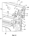
фигура 1 представляет собой частичный и схематический вид в перспективе бытовой кухонной плиты согласно настоящему изобретению;Figure 1 is a partial and schematic perspective view of a domestic cooker according to the present invention;
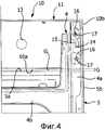
фигура 2 представляет собой схематический и частичный разобранный вид в перспективе верхнего углового участка плиты на фигуре 1, если смотреть с его задней стороны;figure 2 is a schematic and partial exploded perspective view of the upper corner portion of the plate in figure 1, when viewed from its rear side;
фигуры 3 и 4 представляют собой виды сбоку участка на фигуре 2 на двух различных этапах сборки;figures 3 and 4 are side views of the plot in figure 2 at two different stages of assembly;
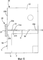
фигура 5 представляет собой вид спереди углового участка на фигуре 4, если смотреть с его передней стороны.figure 5 is a front view of the corner portion in figure 4, when viewed from its front side.
Описание предпочтительных вариантов выполнения изобретенияDescription of preferred embodiments of the invention
Ссылка на "вариант выполнения" или "один вариант выполнения" в структуре этого описания означает обозначение особой конфигурации, конструкции или характеристики, описанных относительно варианта выполнения, содержащихся в по меньшей мере одном варианте выполнения. В результате, фразы, такие как "в варианте выполнения" или "в одном варианте выполнения" и т.п., которые могут быть представлены в различных местах этого описания, необязательно все относятся к одному и тому же варианту выполнения. В дополнение особые конфигурации, конструкции или характеристики могут быть объединены любым целесообразным образом в одном или более вариантах выполнения. Ссылки, используемые далее, обеспечены только для удобства и не определяют сферу защиты или объем охраны вариантов выполнения.A reference to an “embodiment” or “one embodiment” in the structure of this description means a particular configuration, structure, or characteristic described with respect to an embodiment contained in at least one embodiment. As a result, phrases such as “in an embodiment” or “in one embodiment” and the like, which may be presented at various places in this description, do not necessarily all refer to the same embodiment. In addition, particular configurations, structures, or characteristics may be combined in any suitable manner in one or more embodiments. The references used hereinafter are provided for convenience only and do not define the scope of protection or scope of protection of the embodiments.
На фигуре 1 бытовая кухонная плита согласно настоящему изобретению обозначена в целом ссылочной позицией 1. В примере приведенного варианта выполнения плита 1 представляет собой встроенную печь, но изобретение должно быть понято, как также применяемое к другим типам кухонных плит, имеющих переднюю дверцу и характерное покрытие переднего элемента выше или ниже дверцы.In Figure 1, a domestic stove according to the present invention is generally indicated by 1. In the example of the embodiment shown, stove 1 is an integrated oven, but the invention should be understood as also applicable to other types of stoves having a front door and a characteristic front cover element above or below the door.
Печь 1 имеет неподвижную конструкцию, обозначенную в целом ссылочной позицией 2. В проиллюстрированном в высокой степени схематическом примере эта неподвижная конструкция 2 содержит корпус 3 муфеля, относительно которого спереди закреплен передний компонент 4, в частности каркас, включающий по меньшей мере два противоположных вертикальных элемента и промежуточный поперечный элемент. Далее для простоты передний компонент 4 будет обозначаться каркасом.The furnace 1 has a fixed structure, generally indicated by the
К конструкции 2, в частности, но необязательно, к компоненту 4 шарнирно присоединена дверца, обозначенная в целом ссылочной позицией 5. Дверца 5 содержит соответственный каркас 6, на котором установлена покрывающая панель 7, например, изготовленная из стекла. Дверца 5 шарнирно соединена в нижней части с конструкцией 2 так, что она может поворачиваться вокруг, по существу, горизонтальной оси, с помощью средств шарнирного соединения (не видны), относящихся к известному самому по себе типу. Альтернативно дверца 5 шарнирно соединена латерально с конструкцией 2 так, что она может поворачиваться вокруг, по существу, вертикальной оси. Рукоятка дверцы 5 не проиллюстрирована на фигурах, на них видны только соответствующие отверстия под крепления, обозначенные ссылочной позицией 8.To the
Покрывающий элемент в целом обозначен ссылочной позицией 10, который в одном варианте выполнения установлен в неподвижном положении на конструкции 2 выше дверцы 5. В предпочтительном варианте выполнения, как показано, покрывающий элемент 10 обеспечивает переднюю поверхность пользовательского интерфейса или панели управления. Что касается непроиллюстрированного покрывающего элемента 8, он представляет собой либо средства управления либо/или средства индикации указанной панели, при этом выделены только два отверстия 13, но лишь в качестве примера, для прохождения приводных валов, являющихся частью соответственных средств управления печи (не представлены), например, поворотных переключателей. Очевидно, панель управления может содержать более двух средств управления и/или также визуальных аварийных элементов, в случае чего покрывающий элемент 10 по возможности предусматривает другие отверстия или сквозные гнезда. Средства управления также могут быть сенсорного типа, в случае чего необязательно обеспечивать элемент 10 отверстиями 13, представленными на фигурах.The covering element is generally indicated at 10, which, in one embodiment, is mounted in a fixed position on the
В примере проиллюстрированного варианта выполнения покрывающий элемент 10 включает главный корпус 11, предпочтительно образованный отливкой термопластичного материала, имеющий переднюю стенку 11a, на которую крепится, например с помощью клея, пластина 12, имеющая целью придание эстетичного внешнего вида. Эта пластина 12 может, например, быть изготовлена из стекла и нести в себе индикаторные сериграфы для средств управления и/или индикации панели управления (не представлены).In an example of the illustrated embodiment, the
Между нижним краем покрывающего элемента 10 и верхним краем дверцы 5, когда она закрыта, определен промежуток, обозначенный на фигуре 1 позицией G. В предпочтительном варианте выполнения промежуток G, в дополнение имеющий функцию обеспечения свободного перемещения при открывании и закрытии дверцы 5, без какого-либо столкновения с элементом 10, используется по меньшей мере частично в качестве выпуска для газов или испарений, вытесняемых из муфеля 3. В одном варианте выполнения для этого промежуток G имеет высоту приблизительно 4 мм.Between the lower edge of the
В случае когда плита 1 обеспечена системой для охлаждения дверцы, нацеленной на создание (например, за счет действия тангенциального вентилятора) потока охлаждающего воздуха через внутренний зазор на дверцу 5, промежуток G также может быть использован для подачи или разгрузки охлаждающего воздуха: в этом случае высота промежутка G будет предпочтительно составлять более 4 мм, например, приблизительно 8 мм или иначе приблизительно 14 мм в случае, когда плита 1 представляет собой пиролитическую печь.In the case when the plate 1 is provided with a system for cooling the door, aimed at creating (for example, due to the action of the tangential fan) a flow of cooling air through the internal gap on the
На фигуре 2 участок переднего элемента может быть рассмотрен с его задней стороны. На указанной фигуре задняя часть дверцы 5 также является частично видимой. В примере каркас 4 содержит по меньшей мере два вертикальных боковых элемента, только один из которых может быть рассмотрен и обозначен ссылочной позицией 4а, и по меньшей мере один поперечный элемент, предпочтительно два поперечных элемента, только один из которых является видимым и обозначен ссылочной позицией 4b. В одном варианте выполнения верхний поперечный элемент 4b находится в промежуточном положении между двумя концами вертикального элемента 4.In figure 2, a section of the front element can be viewed from its rear side. In the figure, the back of the
Как объяснено ранее, в кухонной плите, относящейся к типу, рассмотренному здесь, дверца 5 и покрывающий элемент 10 должны быть установлены относительно неподвижной конструкции 2 таким образом, что в условиях закрытия дверцы 5 между нижним краем или стенкой покрывающего элемента 10, обозначенной ссылочной позицией 10а, и верхним краем 5а дверцы 5, обозначенной ссылочной позицией 5а, определен промежуток G на фигуре 1. Более того, боковой край или стенка покрывающего элемента 10 и боковой край 5b дверцы 5 на фигуре 2 обозначены ссылочными позициями 10b и 5b соответственно.As explained previously, in a stove of the type discussed here, the
Покрывающий элемент 10 крепится в неподвижном положении к каркасу 4 с помощью крепежных средств, которые включают резьбовые элементы 18, обычно представленные винтами, имеющими головку 18а и резьбовой стержень 18b.The
Согласно характеристике изобретения, передний компонент или каркас 4 конструкции 2 и покрывающий элемент 10 обеспечены средствами для взаимного сцепления, которые содержат первое средство сцепления на раме 4 и второе средство сцепления на покрывающем элементе 10, причем первое и второе средство сцепления предварительно выполнены с возможностью обеспечивать между ними нежесткое или свободное соединение с люфтом.According to a feature of the invention, the front component or
Согласно другой характеристике изобретения, средства, используемые для крепления покрывающего элемента 10 на переднем компоненте или каркасе 4, обеспечены для обеспечения покрывающего элемента 10 закрепляемым в одном из множества возможных альтернативных положений, обеспеченных люфтом, выполняемым между вышеуказанными первым и вторым средствами сцепления.According to another characteristic of the invention, the means used to fasten the
Как будет показано более ясно далее, согласно предпочтительной характеристике изобретения, вышеуказанные средства для взаимного сцепления выполнены с возможностью поддерживать покрывающий элемент 10 на компоненте или каркасе 4 в соответственном состоянии нежесткого соединения, также до того, как элемент 10 окончательно крепится в соответствующем неподвижном положении, полученном с помощью вышеуказанных крепежных средств.As will be shown more clearly below, according to a preferred characteristic of the invention, the aforementioned means for interlocking are adapted to maintain the covering
Согласно другой предпочтительной характеристике изобретения, вышеуказанные средства для взаимного сцепления выполнены с возможностью обеспечивать люфт в более чем одном направлении покрывающего элемента относительно переднего элемента, в частности по меньшей мере в в общем вертикальном направлении и в в общем поперечном направлении, для обеспечения:According to another preferred characteristic of the invention, the aforementioned means for interlocking are configured to provide play in more than one direction of the covering element relative to the front element, in particular in at least the general vertical direction and the general transverse direction, to provide:
- выравнивания нижнего края 10а покрывающего элемента 10 относительно верхнего края 5а дверцы 5 с двумя вышеуказанными краями на расстоянии от и параллельно друг другу для определения промежутка G; и- aligning the
- выравнивания бокового края 10b покрывающего элемента 10 относительно бокового края 5b дверцы 5.- aligning the
Как может быть видно на фигуре 2, в одном варианте выполнения первое средство сцепления содержит по меньшей мере один язычок, выступающий вперед от передней рамы 4, обозначенный ссылочной позицией 14. На другой стороне второе средство сцепления содержит по меньшей мере одно гнездо для зацепления с люфтом язычка 14. Это гнездо зацепления, обозначенное ссылочной позицией 15, определено подобно карману на задней части покрывающего элемента 10, в частности в передней стенке 11a ее корпуса 11. В примерном варианте выполнения корпус 11 изготовлен из отлитого термопластичного материала, а гнездо 15 изготовлено как одно целое в задней части его стенки 11a. В примере указанное гнездо 15 в основном состоит из выступа или рельефа задней поверхности стенки 11а корпуса 11, который является полым и открывается в нижней части для того, чтобы обеспечивать вставку язычка 14. В примерном варианте выполнения на фигурах язычок 14 в общем обращен вверх и продолжается, по существу, параллельно передней поверхности рамы 4: однако будет принято во внимание, что язычок 14 также может быть по возможности незначительно наклонен.As can be seen in FIG. 2, in one embodiment, the first engagement means comprises at least one tongue protruding forward from the
Должно быть отмечено, что обратная конструкция средств сцепления также возможна, т.е. с язычком 14 на задней части стенки 11a корпуса 11 и с гнездом 15 на передней части рамы 4. В одной такой конфигурации язычок на корпусе 11 будет устанавливаться выступающим вниз, и в то же время гнездо 15 будет открываться вверх.It should be noted that a reverse clutch design is also possible, i.e. with the
Снова на фигуре 2 крепежные средства, используемые для крепления покрывающего элемента 10 к каркасу 4 в неподвижном положении, содержат множество отверстий, образованных в передней части каркаса 4. На фигуре 2 выделены два указанных сквозных отверстия, обозначенных ссылочной позицией 16, которые имеют диаметр, или в любом случае размер в поперечном сечении, больший, чем в сечении стержня резьбовых элементов, используемых для крепления. На другой стороне, т.е. на покрывающем элементе 10, крепежные средства включают множество гнезд 17 для приема концевого участка стержня вышеуказанных резьбовых элементов. На фигуре 2 вышеуказанные принимающие гнезда обозначены ссылочной позицией 17, и в то же время резьбовые элементы, здесь представленные винтами, предпочтительно обладающие особенностью в том, что они являются самонарезающими, обозначены ссылочной позицией 19, с соответствующей головкой 18а и соответствующим стержнем 18b.Again, in FIG. 2, the fastening means used to fasten the
В примере приведенного варианта выполнения гнезда 17 определены выступами 19, которые выступают от задней поверхности стенки 11a корпуса 11 и имеют один конец, который в неподвижном состоянии покрывающего элемента 10 касается передней поверхности рамы 4, которая окружает соответственное сквозное отверстие 16. Каждое гнездо 17, определенное в выступах 19, имеет размеры поперечного сечения, совпадающие с диаметром резьбового стержня 18b винтов 18, и в результате меньше размеров поперечного сечения или диаметра сквозных отверстий 16. Очевидно также концы выступов 19, которые касаются каркаса 4, имеют размеры поперечного сечения, большие размеров соответствующих отверстий 16, так что может быть создано подходящее соединение между выступами 19 и каркасом 4. В одном варианте выполнения, как в проиллюстрированном случае, каждое отверстие 16 образовано в нижней части соответственной выемки каркаса 4, здесь приблизительно круглой формы, причем они имеют размеры поперечного сечения, большие вышеуказанных концов выступов 19, для обеспечения необходимого люфта между частями. Эти выемки, когда присутствуют, способствуют облегчению позиционирования между частями на фазе сборки.In the example of the illustrated embodiment, the
Каркас 4 имеет две противоположные боковые области, где покрывающий элемент 10 закреплен в двух соответственных противоположных боковых областях с помощью вышеуказанных крепежных средств 16-19: на фигуре 2 только одна из этих боковых областей каркаса 4 (в основном соответствующая стойке 4а) и покрывающего элемента 10 может быть рассмотрена, причем понятно, что противоположные области выполнены подобным образом.The
Предпочтительно каждая из вышеуказанных боковых областей каркаса имеет два сквозных отверстия 16 в положении одно поверх другого, и каждая боковая область покрывающего элемента 10 имеет два принимающих гнезда 17, в частности с соответственными выступами 19 в положении один поверх другого, с первым и вторым средствами сцепления, которые размещены в промежуточном положении между отверстиями 16 и гнездами 17. Вследствие этого, со ссылкой на пример проиллюстрированного варианта выполнения язычок 14 располагается между двумя сквозными отверстиями 16, и в то же время гнездо 15 располагается между двумя гнездами 17.Preferably, each of the above side regions of the frame has two through
Как было сказано, очень предпочтительно в представленном варианте выполнения корпус 11 изготовлен из отлитого термопластичного материала так, чтобы встраивать оба соответствующих крепежных средства, т.е. принимающие гнезда 17 или соответствующие выступы 19 и соответствующие средства сцепления, т.е. гнезда 15. В одном таком варианте выполнения крепежные винты 18 являются предпочтительно самонарезающими винтами. Следует отметить, что резьбовые крепежные элементы также могут относиться к типу, отличному от приведенного в качестве примера (например, болтам и гайкам), даже если они могут усложнять сборку.As has been said, it is very preferable in the presented embodiment that the
Принцип крепления компонентов, проиллюстрированных ранее, и в частности покрывающего элемента 10 является очень простым и обеспечивает возможность преодоления типичных проблем известного уровня техники.The principle of fastening the components illustrated previously, and in particular the covering
На фазе изготовления обеспечивается неподвижная конструкция 2, которая содержит каркас 4, при этом дверца 5 собирается отдельно согласно известной самой по себе технологии. Подобным образом получают покрывающий элемент 10, который, как было сказано, предпочтительно содержит корпус 11, изготовленный из отлитого термопластичного материала так, чтобы определять различные функциональные элементы, описанные ранее, к которому далее спереди прикладывается пластина 12, например, приклеиванием.In the manufacturing phase, a fixed
Затем дверца 5 шарнирно соединяется с неподвижной конструкцией 2 с помощью известных самих по себе методов. С этой целью могут быть использованы известные шарниры, которые прикрепляются между каркасом 6 дверцы и, например, каркасом 4 в нижней области последнего. После крепления и выравнивания дверцы относительно каркаса 4 к конструкции 2 в неподвижном положении, т.е. к каркасу 4, крепится покрывающий элемент 10.Then, the
Как уже объяснено ранее, крепление дверцы 5 и покрывающего элемента 10 на конструкции должно быть таким, что в состоянии, когда дверца закрыта, нижний край 10а покрывающего элемента 10 находится на расстоянии от верхнего края 5а дверцы 5 так, чтобы определять промежуток G с двумя краями, которые параллельны друг другу.As previously explained, the fastening of the
Согласно изобретению и как уже объяснено ранее, каркас 4 обеспечен первыми средствами сцепления, которые в проиллюстрированном примере представлены язычками 14, а покрывающий элемент 10 обеспечен вторыми средствами сцепления, представленными в примере гнездами 15. Как видно, эти первые и вторые средства сцепления могут быть соединены вместе свободным образом с люфтом. Подобным образом крепежные средства 16-19 обеспечены в целях, приведенных ранее, т.е. так, чтобы обеспечивать покрывающий элемент 10 закрепляемым в неподвижном положении на каркасе 4 в одном из множества возможных альтернативных положений, которые обеспечиваются люфтом, выполняемым между средствами 14-15 сцепления.According to the invention, and as already explained earlier, the
В связи с этим следует отметить в отношении этого, что ширина язычка 14 меньше ширины полости гнезда 15 таким образом, что в состоянии, когда два язычка 14 соединены с соответствующими гнездами 15, покрывающий элемент 10 может быть смещен вручную вправо и влево относительно каркаса 4 в состоянии нежесткого соединения средств сцепления. Подобным образом следует отметить, что вертикальное продолжение или продолжение в высоту язычка 14 меньше соответственного размера гнезда 15, чтобы обеспечивать - снова в состоянии нежесткого соединения - существенное смещение также в вертикальном направлении без появления расцепления между язычками и гнездами.In this regard, it should be noted in relation to this that the width of the
В целях сборки покрывающий элемент 10 соединяется свободным образом с каркасом 4 с помощью соединения средств сцепления, обеспеченных между двумя рассматриваемыми частями, т.е. язычками 14 и гнездами 15. В этом состоянии покрывающий элемент 10 уже поддерживается на каркасе 4, даже если конечное крепление еще не выполнено. Это облегчает выполнение операций, которые должен выполнять оператор, ответственный за сборку, поскольку он не должен поддерживать покрывающий элемент 10 в требуемом положении вручную. Здесь и если необходимо оператор может смещать покрывающий элемент 10 относительно каркаса 4 до тех пор, пока не установится требуемое конечное положение крепления. Это конечное положение крепления может быть установлено оператором из числа множества возможных альтернативных положений, которые обеспечиваются, с одной стороны, люфтом, определенным средствами 14-15 сцепления, и, с другой стороны, благодаря тому, что люфт также возможен между крепежными винтами 18 и сквозными отверстиями 16 (как было сказано; к тому же поперечное сечение стержня 18b винтов 18 определенно меньше диаметра сквозных отверстий 16). На практике оператор может смещать вправо или влево, вверх или вниз покрывающий элемент 10, хоть и в состоянии нежесткого соединения с каркасом 4, до тех пор, пока не установится требуемое положение выравнивания краев 10а, 5а, 10b, 5b. Как только это положение установлено, оператор переходит к конечному креплению с помощью винтов 18. Эти винты 18 завинчиваются с задней стороны каркаса 4 (т.е. из положения, видимого на фигуре 2), при этом винты 18 вставляются навылет в отверстия 16 и их участок вершины, который ввинчивается в гнезда 17 выступов 19. Головки 18 винтов 18 касаются поверхности, которая окружает отверстия 16, в задней части каркаса 4. Затягиванием винтов поверхность головки выступов 19 подходит к передней поверхности каркаса 4, пока она не коснется ее в области, окружающей отверстия 16. Когда винты 18 затягиваются, получается конечное крепление в требуемом положении.For assembly purposes, the covering
Для более ясного представления сборки может быть выполнена ссылка на фигуры 3 и 4. Фигура 3 иллюстрирует первый этап сцепления с нежестким соединением, где покрывающий элемент 10 зацепляется с каркасом 4 с помощью язычков 14 и гнезд 15. В указанном состоянии вертикальное зацепление между язычками и гнездами является максимальным в том смысле, что нижний край гнезд 15 касается удлинения язычков 14, которое, по существу, является ортогональным или поперечным передней поверхности каркаса 4. Как может быть отмечено на фигуре 3, в указанном состоянии расстояние между нижним краем 10а элемента 10 и верхним краем 5а дверцы является минимальным. На фигуре 3 более того может быть отмечено, как в указанном состоянии гнезда 17 или иначе выступы 19 находятся в первом положении относительно отверстий 16.For a clearer view of the assembly, reference can be made to FIGS. 3 and 4. FIG. 3 illustrates a first non-rigid engagement step where the
Здесь, как было сказано, оператор может смещать элемент 10, используя люфт, обеспеченный средствами 14-15 сцепления и крепежными средствами 16-19, для размещения положения, считающегося оптимальным для конечного крепления. Фигура 4 представляет такое размещение, которое, но лишь путем примера, показывает принимающие гнезда 17, расположенные по центру относительно отверстий 16. Как было сказано, это представляет собой состояние, проиллюстрированное полностью путем примера, поскольку выравнивание между краями 10а и 5а может быть получено также с различным относительным положением между гнездами 17 и отверстиями 16 в пределах, обеспеченных люфтом, выполняемым между этими частями.Here, as was said, the operator can bias the
В предпочтительном варианте выполнения изобретения средства 14-15 сцепления, размеры сквозных отверстий 16 и диаметр стержней 18b винтов 18 выбраны предпочтительно с возможностью обеспечения люфта в более чем одном направлении (вверх, вниз, вправо, влево, по диагонали) на по меньшей мере 2 мм в каждом направлении: в указанной перспективе, например, отверстия 16 могут иметь номинальный диаметр 8 мм (когда они имеют круглую форму, как проиллюстрировано), и в то же время поперечное сечение стержня 18b винтов 18 будет иметь номинальный диаметр 4 мм.In a preferred embodiment of the invention, the clutch means 14-15, the dimensions of the through
Средства сцепления, образованные язычками 14 и гнездами 15, могут обеспечивать также незначительный люфт в переднем направлении. Как может быть легко понятно, когда винты 18 затягиваются, получают незначительное смещение покрывающего элемента 10 по направлению к передней поверхности каркаса 4; с другой стороны, даже при отсутствии люфта в переднем направлении затягивание винтов 18 может быть таким, чтобы вызывать изгибания или деформацию язычков 14 назад.The clutch means formed by the
В особенно предпочтительном варианте выполнения способа согласно изобретению операция идентификации положения крепления, считающегося оптимальным, выполняют оператором с использованием по меньшей мере одного позиционирующего шаблона. Один такой шаблон обозначен в целом ссылочной позицией 20 на фигуре 5.In a particularly preferred embodiment of the method according to the invention, the operation of identifying the attachment position considered to be optimal is performed by the operator using at least one positioning template. One such template is indicated generally by the
Предпочтительно используемый шаблон выполнен с возможностью обеспечивать выравнивание или параллельность между нижним краем 10а покрывающего элемента 10 и верхним краем 5а дверцы 5 с двумя вышеуказанными краями на расстоянии один от другого для определения промежутка G, а также выравнивание бокового края 10b покрывающего элемента 10 с боковым краем 5b дверцы.Preferably, the pattern used is configured to align or parallelize between the
В примере варианта выполнения на фигуре 5 с этой целью шаблон 20 содержит два участка 21 и 22, в общем ортогональных друг другу. Участок 21 имеет заданную толщину, по существу, соответствующую высоте требуемого промежутка G. Этот участок 21 имеет две противоположные поверхности, обозначенные ссылочными позициями 21а и 21b, выполненными с возможностью приходить в контакт с краями 10а и 5а, соответственно. Второй участок 22 имеет две копланарные поверхности 22а и 22b, выполненные с возможностью приходить в контакт с боковым краем 10b и боковым краем 5b элемента 10 и дверцы 5 соответственно.In the example embodiment of FIG. 5, for this purpose, the
Как может быть легко понятно на фигуре 5, вставкой шаблона 20 в проиллюстрированное положение возможно получать простое выравнивание краев 10а и 5а и выравнивание краев 10b и 5b. В проиллюстрированном примере шаблон 20 содержит участки 21 и 22, соответствующие только боковой области группы, образованной дверцей 5 и покрывающим элементом 10, но очевидно шаблон может быть разработан с возможностью обеспечения одновременного выравнивания на обеих сторонах, т.е. с участками 21 и 22, зеркальными в отношении участков, видимых на фигуре 5.As can be easily understood in FIG. 5, by inserting the
Изобретение описано ранее со ссылкой на покрывающий элемент для пользовательского интерфейса, который размещен выше дверцы кухонной плиты. Будет принято во внимание, однако, что такая же идея может быть применена также в случае, когда пользовательский интерфейс размещен под дверцей плиты, при этом понятна необходимость обеспечения промежутка G в этом случае между верхним краем покрывающего элемента и нижним краем дверцы. Вариант выполнения этого вида, например, показан в случае встроенных печей для установки в колонну, в котором он может подтверждать удобство обеспечения пользовательского интерфейса под дверцей, в положении, которое для некоторых конечных пользователей может быть рассмотрено более предпочтительным с эргономической точки зрения.The invention has been described previously with reference to a covering element for a user interface that is positioned above a stove door. It will be appreciated, however, that the same idea can also be applied when the user interface is located under the door of the slab, while the need to ensure a gap G in this case between the upper edge of the covering element and the lower edge of the door is understood. An embodiment of this type, for example, is shown in the case of built-in ovens for installation in a column in which it can confirm the convenience of providing a user interface under the door in a position that for some end users may be considered more preferable from an ergonomic point of view.
Разумеется, без ущерба принципу изобретения детали конструкции и варианты выполнения могут изменяться относительно того, что описано и проиллюстрировано здесь полностью путем примера, при этом, без отклонения от объема охраны, определенного следующей далее формулой изобретения.Of course, without prejudice to the principle of the invention, the construction details and embodiments can be changed relative to what is described and illustrated here by way of example, without deviating from the scope of protection defined by the following claims.
Наконец, настоящее изобретение может находить применение в других электрических бытовых устройствах, имеющих дверцу и переднюю панель управления, как, например, посудомоечная машина.Finally, the present invention may find application in other electrical household appliances having a door and a front control panel, such as a dishwasher.
Claims (15)
одно из первого и второго средств (14-15) сцепления содержит, по меньшей мере, один выступающий язычок (14) одного из переднего компонента (4) и покрывающего элемента (10), и
другое одно из первого и второго средств (14-15) сцепления содержит, по меньшей мере, одно гнездо для зацепления с люфтом (15) соответственного язычка (14), причем гнездо для зацепления (15) находится на другом одном из переднего компонента (4) и покрывающего элемента (10).4. A household stove according to claim 2, characterized in that
one of the first and second coupling means (14-15) comprises at least one protruding tongue (14) of one of the front component (4) and the covering element (10), and
the other one of the first and second coupling means (14-15) comprises at least one socket for engagement with the play (15) of the corresponding tongue (14), the socket for engagement (15) being on the other one of the front component (4 ) and the covering element (10).
по меньшей мере, один язычок (14) выступает вперед от передней поверхности переднего компонента (4) и по существу направлен вверх, и
по меньшей мере, одно гнездо для зацепления (15) выполнено как часть, выступающая назад от задней части покрывающего элемента (10), и определяет гнездо, открытое вниз, для введения язычка (14).5. A household stove according to claim 4, characterized in that
at least one tongue (14) protrudes forward from the front surface of the front component (4) and is essentially directed upward, and
at least one engagement slot (15) is formed as a part protruding backward from the back of the covering element (10), and defines a slot open downward for introducing a tongue (14).
множество сквозных отверстий (16), образованных в переднем компоненте (4), причем каждое отверстие (16) имеет размеры диаметра или поперечного сечения, превышающие поперечное сечение стержня (18b) соответственного указанного резьбового элемента (18), и
множество принимающих гнезд (17) для участка стержня (18b) соответственного указанного резьбового элемента (18), причем каждое принимающее гнездо (17) имеет размеры диаметра или поперечного сечения, меньшие размеров диаметра или поперечного сечения соответственного указанного сквозного отверстия (16).6. A household stove according to claim 1, characterized in that the fastening means (16-19) comprise:
a plurality of through holes (16) formed in the front component (4), each hole (16) having a diameter or cross section greater than the cross section of the rod (18b) of the corresponding threaded element (18), and
a plurality of receiving sockets (17) for a portion of the shaft (18b) of the corresponding threaded element (18), each receiving socket (17) having a diameter or cross section smaller than the diameter or cross section of a corresponding through hole (16).
средства (14-15) взаимного сцепления содержат для каждой указанной боковой области переднего компонента (4) один из указанного язычка (14) и указанного гнезда для зацепления (15) в положении между двумя указанными сквозными отверстиями (16) и для каждой указанной боковой области покрывающего элемента (10) другой один из указанного язычка (14) и указанного гнезда для зацепления (15) в положении между двумя указанными принимающими гнездами (17).8. The stove according to paragraphs. 4, 6 and 7, characterized in that the fastening means (16-19) contain for each specified side region of the front component (4) two indicated through holes (16) at different heights on the front component (4) and for each specified side region the covering element (10) two indicated receiving sockets (17) at different heights on the covering element (10), and
the mutual engagement means (14-15) comprise, for each said side region of the front component (4), one of said tongue (14) and said engagement slot (15) in a position between two said through holes (16) and for each said side region the covering element (10) another one of the specified tongue (14) and the specified slot for engagement (15) in the position between the two specified receiving sockets (17).
указанные принимающие гнезда (17) содержат выступы (19), в общем выступающие от задней части покрывающего элемента (10) и имеющие один конец, который в неподвижном состоянии покрывающего элемента (10) стыкуется с передней поверхностью переднего компонента (4), окружающего соответственное указанное сквозное отверстие (16), причем выступы (19) имеют размеры диаметра или поперечного сечения, превышающие соответственные сквозные отверстия (16).9. A stove according to claim 6, characterized in that
said receiving sockets (17) comprise protrusions (19) generally protruding from the rear of the covering element (10) and having one end which, in the stationary state of the covering element (10), mates with the front surface of the front component (4) surrounding the corresponding a through hole (16), and the protrusions (19) have dimensions of diameter or cross section greater than the corresponding through holes (16).
второго средств (14-15) сцепления, и в котором резьбовые элементы включают в себя самонарезающие винты (18).10. A stove according to claim 1, characterized in that the covering element (10) includes a housing made of plastic material (11), in which the specified receiving socket (17) and one of the first and
second means of coupling (14-15), and in which the threaded elements include self-tapping screws (18).
a) обеспечивают неподвижную конструкцию (2) плиты (1),
b) обеспечивают переднюю дверцу (5) плиты (1);
c) обеспечивают покрывающий элемент (10) плиты (1), в частности покрывающий элемент пользовательского интерфейса,
d) шарнирно соединяют дверцу (5) с передней областью конструкции (2),
e) крепят покрывающий элемент (5) в неподвижном положении на конструкции (2) выше или ниже дверцы (5),
причем на этапах d) и е) крепят дверцу (5) и покрывающий элемент (10) на конструкции (2) таким образом, что в закрытом состоянии дверцы (5) между нижним краем (10а), соответственно верхним краем, покрывающего элемента (10) и верхним краем (5а), соответственно нижним краем, дверцы (5) был образован промежуток (G),
и на этапах а) и с) получают передний компонент (4) конструкции (2) и покрывающий элемент (10) таким образом, что покрывающий элемент (10) может быть закреплен в неподвижном положении на переднем компоненте (4) с помощью крепежных средств (16-19), включающих в себя резьбовые элементы (18),
при этом на этапах а) и с) дополнительно предварительно выполняют передний компонент (4) с первым средством сцепления (14) и покрывающий элемент (10) со вторым средством сцепления (15), причем первое и второе средства (14-15)
сцепления являются соединяемыми друг с другом нежестким образом и с люфтом между ними;
на этапе е) осуществляют операции, на которых:
e1) сцепляют нежестким образом покрывающий элемент (10) с передним компонентом (4) с помощью зацепления первого средства (14) сцепления со вторым средством (15) сцепления; и
е2) крепят в неподвижном положении покрывающий элемент (10) к переднему компоненту (4) с помощью резьбовых элементов (18),
отличающийся тем, что
на этапах а) и с) дополнительно предварительно выполняют крепежные средства (16-19) так, чтобы обеспечивать возможность закрепления покрывающего элемента (10) в неподвижном положении на переднем компоненте (4) в одном из множества возможных альтернативных положений, обеспеченных люфтом, выполняемым между первым средством (14) сцепления и вторым средством (15) сцепления; и
на этапе е) между операциями e1) и е2) осуществляют дополнительную операцию, на которой смещают покрывающий элемент (10) относительно переднего компонента (4), пока не установится требуемое положение крепления среди указанного множества возможных альтернативных положений.12. The method of assembly of the front components of stoves according to any one of paragraphs. 1-11, in particular furnaces, according to which:
a) provide a fixed structure (2) of the plate (1),
b) provide the front door (5) of the plate (1);
c) provide a cover element (10) of the plate (1), in particular a cover element of the user interface,
d) pivotally connect the door (5) to the front area of the structure (2),
e) fastening the covering element (5) in a fixed position on the structure (2) above or below the door (5),
moreover, in steps d) and e) the door (5) and the covering element (10) are fastened to the structure (2) in such a way that in the closed state of the door (5) between the lower edge (10a), respectively, the upper edge of the covering element (10) ) and the upper edge (5a), respectively the lower edge of the door (5), a gap (G) was formed,
and in steps a) and c), the front component (4) of the structure (2) and the cover element (10) are obtained in such a way that the cover element (10) can be fixed in a fixed position on the front component (4) using fastening means ( 16-19), including threaded elements (18),
at the same time, at steps a) and c), the front component (4) with the first coupling means (14) and the covering element (10) with the second coupling means (15) are additionally preliminarily performed, the first and second means (14-15)
couplings are connected to each other in a non-rigid manner and with play between them;
at the stage e) carry out operations in which:
e1) engaging the cover member (10) in a non-rigid manner with the front component (4) by engaging the first coupling means (14) with the second coupling means (15); and
e2) fasten in a fixed position, the covering element (10) to the front component (4) using threaded elements (18),
characterized in that
in steps a) and c), fastening means (16-19) are additionally preliminarily performed so as to enable the covering element (10) to be fixed in a fixed position on the front component (4) in one of the many possible alternative positions provided by a play performed between first clutch means (14) and second clutch means (15); and
in step e), between operations e1) and e2), an additional operation is carried out, on which the covering element (10) is shifted relative to the front component (4) until the required fastening position is established among the specified set of possible alternative positions.
выравнивания нижнего края (10а), соответственно верхнего края, покрывающего элемента (10) относительно верхнего края (5а), соответственно нижнего края, дверцы (5) с двумя вышеуказанными краями (10а, 5а), разнесенными друг от друга для образования указанного промежутка (G), и
выравнивания бокового края (10b) покрывающего элемента (10) относительно бокового края (5b) дверцы (5). 15. The method according to p. 12, characterized in that the operation el) is performed using at least one positioning template (20), made in particular in order to carry out at least one of
alignment of the lower edge (10a), respectively, of the upper edge of the covering element (10) relative to the upper edge (5a), respectively of the lower edge, of the door (5) with the two above-mentioned edges (10a, 5a) spaced from each other to form the specified gap ( G) and
aligning the side edge (10b) of the covering element (10) with respect to the side edge (5b) of the door (5).
Applications Claiming Priority (3)
| Application Number | Priority Date | Filing Date | Title |
|---|---|---|---|
| IT000286A ITTO20100286A1 (en) | 2010-04-13 | 2010-04-13 | DOMESTIC COOKING APPLIANCE, PARTICULARLY AN OVEN |
| ITTO2010A000286 | 2010-04-13 | ||
| PCT/IB2011/051606 WO2011128864A1 (en) | 2010-04-13 | 2011-04-13 | Household cooking appliance |
Publications (2)
| Publication Number | Publication Date |
|---|---|
| RU2012148069A RU2012148069A (en) | 2014-05-20 |
| RU2559996C2 true RU2559996C2 (en) | 2015-08-20 |
Family
ID=42989473
Family Applications (1)
| Application Number | Title | Priority Date | Filing Date |
|---|---|---|---|
| RU2012148069/03A RU2559996C2 (en) | 2010-04-13 | 2011-04-13 | Household cooking stove |
Country Status (4)
| Country | Link |
|---|---|
| EP (1) | EP2558784B1 (en) |
| IT (1) | ITTO20100286A1 (en) |
| RU (1) | RU2559996C2 (en) |
| WO (1) | WO2011128864A1 (en) |
Families Citing this family (5)
| Publication number | Priority date | Publication date | Assignee | Title |
|---|---|---|---|---|
| DE102013107618B4 (en) | 2013-07-17 | 2022-10-27 | Miele & Cie. Kg | Cooking device with front frame |
| DE102014217635A1 (en) | 2014-09-03 | 2016-03-03 | BSH Hausgeräte GmbH | household appliance |
| EP3040622B1 (en) * | 2014-12-29 | 2017-11-22 | BSH Hausgeräte GmbH | A home appliance having a coupling element |
| US11460193B2 (en) | 2020-03-13 | 2022-10-04 | Whirlpool Corporation | Leveling assembly |
| USD1005769S1 (en) | 2021-09-08 | 2023-11-28 | Newage Products Inc. | Oven |
Citations (4)
| Publication number | Priority date | Publication date | Assignee | Title |
|---|---|---|---|---|
| DE19520084C1 (en) * | 1995-06-01 | 1996-07-25 | Loh Kg Rittal Werk | Electrical switch cabinet with cladding panels fitted to profile frame |
| DE19649047A1 (en) * | 1996-11-27 | 1998-05-28 | Juno Kuechentech Electrolux | Domestic appliance, e.g. an oven |
| EP1377132A2 (en) * | 2002-06-24 | 2004-01-02 | Samsung Electronics Co., Ltd. | Microwave oven, more particularly a microwave having a customizable control panel |
| RU2306488C1 (en) * | 2005-06-08 | 2007-09-20 | Самсунг Электроникс Ко., Лтд. | Stove |
Family Cites Families (3)
| Publication number | Priority date | Publication date | Assignee | Title |
|---|---|---|---|---|
| US2921576A (en) * | 1956-08-31 | 1960-01-19 | Gen Electric | Securement means for wall-mounted cooking ovens |
| GB2345239B (en) * | 1998-12-30 | 2002-10-23 | Vero Electronics Ltd | Cabinet |
| US7014281B2 (en) * | 2003-04-10 | 2006-03-21 | Maytag Corporation | Fully integrated dishwasher door |
-
2010
- 2010-04-13 IT IT000286A patent/ITTO20100286A1/en unknown
-
2011
- 2011-04-13 EP EP11722541.7A patent/EP2558784B1/en active Active
- 2011-04-13 WO PCT/IB2011/051606 patent/WO2011128864A1/en active Application Filing
- 2011-04-13 RU RU2012148069/03A patent/RU2559996C2/en not_active IP Right Cessation
Patent Citations (4)
| Publication number | Priority date | Publication date | Assignee | Title |
|---|---|---|---|---|
| DE19520084C1 (en) * | 1995-06-01 | 1996-07-25 | Loh Kg Rittal Werk | Electrical switch cabinet with cladding panels fitted to profile frame |
| DE19649047A1 (en) * | 1996-11-27 | 1998-05-28 | Juno Kuechentech Electrolux | Domestic appliance, e.g. an oven |
| EP1377132A2 (en) * | 2002-06-24 | 2004-01-02 | Samsung Electronics Co., Ltd. | Microwave oven, more particularly a microwave having a customizable control panel |
| RU2306488C1 (en) * | 2005-06-08 | 2007-09-20 | Самсунг Электроникс Ко., Лтд. | Stove |
Also Published As
| Publication number | Publication date |
|---|---|
| WO2011128864A1 (en) | 2011-10-20 |
| EP2558784A1 (en) | 2013-02-20 |
| ITTO20100286A1 (en) | 2011-10-14 |
| EP2558784B1 (en) | 2018-06-06 |
| RU2012148069A (en) | 2014-05-20 |
Similar Documents
| Publication | Publication Date | Title |
|---|---|---|
| RU2559996C2 (en) | Household cooking stove | |
| CA2414692C (en) | Oven door assembly | |
| JP2009541699A (en) | Household appliances with hidden hinges | |
| US10208963B2 (en) | Cooking appliance | |
| US11168892B2 (en) | Household cooking appliance | |
| RU2544188C2 (en) | System for kitchen stove components connection | |
| US9784454B2 (en) | Cooktop burner mounting system | |
| CA2461637C (en) | Rear alignment and support system for a cooking appliance cooktop | |
| US20150022068A1 (en) | Front frame for a cooking device | |
| CN205332287U (en) | Combined cooking range | |
| JP2018204852A (en) | Range hood panel fixture | |
| US9982894B1 (en) | Electronic control assembly for an appliance | |
| US11898759B2 (en) | Twist release mechanism for a multi-pane door assembly | |
| US3385284A (en) | Cooking appliance with adjustable control housing | |
| US20230243512A1 (en) | Oven handle locators for controlling door appearance | |
| EP3779283B1 (en) | Cooking oven | |
| US20230148387A1 (en) | Slide and lock appliance handle mounting | |
| US20230085049A1 (en) | Household appliance and handle thereof | |
| KR200349531Y1 (en) | A conclusion structure of controlplate for Electric oven | |
| US20230288074A1 (en) | Cooktop oven gasket location and fasteners | |
| CN112535419B (en) | Furnace gate subassembly and embedded cooking utensil | |
| EP3495739B1 (en) | Cooking device comprising a bezel coupling system with better alignment of knobs and method of assembling such a device | |
| EP3978808B1 (en) | Cooking appliance provided with a door latch assembly | |
| JPS6349614Y2 (en) | ||
| CN2569691Y (en) | Electric cooker |
Legal Events
| Date | Code | Title | Description |
|---|---|---|---|
| MM4A | The patent is invalid due to non-payment of fees |
Effective date: 20170414 |