RU2559503C2 - Method and device for cleaning of filters - Google Patents
Method and device for cleaning of filters Download PDFInfo
- Publication number
- RU2559503C2 RU2559503C2 RU2012141023/05A RU2012141023A RU2559503C2 RU 2559503 C2 RU2559503 C2 RU 2559503C2 RU 2012141023/05 A RU2012141023/05 A RU 2012141023/05A RU 2012141023 A RU2012141023 A RU 2012141023A RU 2559503 C2 RU2559503 C2 RU 2559503C2
- Authority
- RU
- Russia
- Prior art keywords
- filter cloth
- gas flow
- gas
- cleaning station
- filter
- Prior art date
Links
- 238000004140 cleaning Methods 0.000 title claims abstract description 70
- 238000000034 method Methods 0.000 title claims abstract description 25
- 239000004744 fabric Substances 0.000 claims abstract description 164
- 239000000463 material Substances 0.000 claims abstract description 50
- 238000010926 purge Methods 0.000 claims description 7
- 230000001680 brushing effect Effects 0.000 claims description 3
- 238000005096 rolling process Methods 0.000 claims description 3
- 238000007664 blowing Methods 0.000 claims description 2
- 238000001914 filtration Methods 0.000 abstract description 7
- 238000010327 methods by industry Methods 0.000 abstract 1
- 239000000126 substance Substances 0.000 abstract 1
- 239000002245 particle Substances 0.000 description 12
- 239000002699 waste material Substances 0.000 description 11
- 239000000839 emulsion Substances 0.000 description 4
- XLYOFNOQVPJJNP-UHFFFAOYSA-N water Substances O XLYOFNOQVPJJNP-UHFFFAOYSA-N 0.000 description 4
- 239000000356 contaminant Substances 0.000 description 3
- 239000012530 fluid Substances 0.000 description 3
- 239000007788 liquid Substances 0.000 description 3
- 239000002184 metal Substances 0.000 description 3
- 229910052751 metal Inorganic materials 0.000 description 3
- 239000002923 metal particle Substances 0.000 description 2
- 150000002739 metals Chemical class 0.000 description 2
- 239000007787 solid Substances 0.000 description 2
- 230000005540 biological transmission Effects 0.000 description 1
- 230000008602 contraction Effects 0.000 description 1
- 238000005520 cutting process Methods 0.000 description 1
- -1 dirt Substances 0.000 description 1
- 238000006073 displacement reaction Methods 0.000 description 1
- 238000005553 drilling Methods 0.000 description 1
- 238000000227 grinding Methods 0.000 description 1
- 238000009776 industrial production Methods 0.000 description 1
- 239000000314 lubricant Substances 0.000 description 1
- 238000004064 recycling Methods 0.000 description 1
- 239000003507 refrigerant Substances 0.000 description 1
- 238000007790 scraping Methods 0.000 description 1
- 238000003860 storage Methods 0.000 description 1
- 239000004094 surface-active agent Substances 0.000 description 1
Images
Classifications
-
- B—PERFORMING OPERATIONS; TRANSPORTING
- B01—PHYSICAL OR CHEMICAL PROCESSES OR APPARATUS IN GENERAL
- B01D—SEPARATION
- B01D29/00—Filters with filtering elements stationary during filtration, e.g. pressure or suction filters, not covered by groups B01D24/00 - B01D27/00; Filtering elements therefor
- B01D29/62—Regenerating the filter material in the filter
- B01D29/66—Regenerating the filter material in the filter by flushing, e.g. counter-current air-bumps
-
- B—PERFORMING OPERATIONS; TRANSPORTING
- B01—PHYSICAL OR CHEMICAL PROCESSES OR APPARATUS IN GENERAL
- B01D—SEPARATION
- B01D41/00—Regeneration of the filtering material or filter elements outside the filter for liquid or gaseous fluids
-
- B—PERFORMING OPERATIONS; TRANSPORTING
- B01—PHYSICAL OR CHEMICAL PROCESSES OR APPARATUS IN GENERAL
- B01D—SEPARATION
- B01D29/00—Filters with filtering elements stationary during filtration, e.g. pressure or suction filters, not covered by groups B01D24/00 - B01D27/00; Filtering elements therefor
- B01D29/09—Filters with filtering elements stationary during filtration, e.g. pressure or suction filters, not covered by groups B01D24/00 - B01D27/00; Filtering elements therefor with filtering bands, e.g. movable between filtering operations
-
- B—PERFORMING OPERATIONS; TRANSPORTING
- B01—PHYSICAL OR CHEMICAL PROCESSES OR APPARATUS IN GENERAL
- B01D—SEPARATION
- B01D29/00—Filters with filtering elements stationary during filtration, e.g. pressure or suction filters, not covered by groups B01D24/00 - B01D27/00; Filtering elements therefor
- B01D29/62—Regenerating the filter material in the filter
- B01D29/64—Regenerating the filter material in the filter by scrapers, brushes, nozzles, or the like, acting on the cake side of the filtering element
- B01D29/6407—Regenerating the filter material in the filter by scrapers, brushes, nozzles, or the like, acting on the cake side of the filtering element brushes
-
- B—PERFORMING OPERATIONS; TRANSPORTING
- B01—PHYSICAL OR CHEMICAL PROCESSES OR APPARATUS IN GENERAL
- B01D—SEPARATION
- B01D29/00—Filters with filtering elements stationary during filtration, e.g. pressure or suction filters, not covered by groups B01D24/00 - B01D27/00; Filtering elements therefor
- B01D29/62—Regenerating the filter material in the filter
- B01D29/66—Regenerating the filter material in the filter by flushing, e.g. counter-current air-bumps
- B01D29/661—Regenerating the filter material in the filter by flushing, e.g. counter-current air-bumps by using gas-bumps
-
- B—PERFORMING OPERATIONS; TRANSPORTING
- B01—PHYSICAL OR CHEMICAL PROCESSES OR APPARATUS IN GENERAL
- B01D—SEPARATION
- B01D29/00—Filters with filtering elements stationary during filtration, e.g. pressure or suction filters, not covered by groups B01D24/00 - B01D27/00; Filtering elements therefor
- B01D29/62—Regenerating the filter material in the filter
- B01D29/66—Regenerating the filter material in the filter by flushing, e.g. counter-current air-bumps
- B01D29/68—Regenerating the filter material in the filter by flushing, e.g. counter-current air-bumps with backwash arms, shoes or nozzles
- B01D29/688—Regenerating the filter material in the filter by flushing, e.g. counter-current air-bumps with backwash arms, shoes or nozzles with backwash arms or shoes acting on the cake side
-
- B—PERFORMING OPERATIONS; TRANSPORTING
- B01—PHYSICAL OR CHEMICAL PROCESSES OR APPARATUS IN GENERAL
- B01D—SEPARATION
- B01D33/00—Filters with filtering elements which move during the filtering operation
- B01D33/04—Filters with filtering elements which move during the filtering operation with filtering bands or the like supported on cylinders which are impervious for filtering
-
- B—PERFORMING OPERATIONS; TRANSPORTING
- B01—PHYSICAL OR CHEMICAL PROCESSES OR APPARATUS IN GENERAL
- B01D—SEPARATION
- B01D33/00—Filters with filtering elements which move during the filtering operation
- B01D33/44—Regenerating the filter material in the filter
- B01D33/48—Regenerating the filter material in the filter by flushing, e.g. counter-current air-bumps
- B01D33/50—Regenerating the filter material in the filter by flushing, e.g. counter-current air-bumps with backwash arms, shoes or nozzles
- B01D33/503—Regenerating the filter material in the filter by flushing, e.g. counter-current air-bumps with backwash arms, shoes or nozzles the backwash arms, shoes acting on the cake side
-
- B—PERFORMING OPERATIONS; TRANSPORTING
- B01—PHYSICAL OR CHEMICAL PROCESSES OR APPARATUS IN GENERAL
- B01D—SEPARATION
- B01D41/00—Regeneration of the filtering material or filter elements outside the filter for liquid or gaseous fluids
- B01D41/04—Regeneration of the filtering material or filter elements outside the filter for liquid or gaseous fluids of rigid self-supporting filtering material
-
- B—PERFORMING OPERATIONS; TRANSPORTING
- B01—PHYSICAL OR CHEMICAL PROCESSES OR APPARATUS IN GENERAL
- B01D—SEPARATION
- B01D2201/00—Details relating to filtering apparatus
- B01D2201/08—Regeneration of the filter
- B01D2201/081—Regeneration of the filter using nozzles or suction devices
- B01D2201/082—Suction devices placed on the cake side of the filtering element
-
- B—PERFORMING OPERATIONS; TRANSPORTING
- B01—PHYSICAL OR CHEMICAL PROCESSES OR APPARATUS IN GENERAL
- B01D—SEPARATION
- B01D2201/00—Details relating to filtering apparatus
- B01D2201/20—Pressure-related systems for filters
- B01D2201/204—Systems for applying vacuum to filters
Landscapes
- Chemical & Material Sciences (AREA)
- Chemical Kinetics & Catalysis (AREA)
- Filtering Of Dispersed Particles In Gases (AREA)
- Cleaning In General (AREA)
- Treatment Of Fiber Materials (AREA)
Abstract
Description
ОБЛАСТЬ ТЕХНИКИ, К КОТОРОЙ ОТНОСИТСЯ ИЗОБРЕТЕНИЕFIELD OF THE INVENTION
Изобретение относится к способу и устройству для очистки фильтров. В частности, оно относится к способам и устройствам для очистки фильтрующих тканей, используемых в фильтровании рабочих текучих сред.The invention relates to a method and apparatus for cleaning filters. In particular, it relates to methods and devices for cleaning filter cloths used in filtering working fluids.
УРОВЕНЬ ТЕХНИКИBACKGROUND
Рабочие текучие среды для металлов (MWF) используют в качестве смазочных материалов и хладагентов при разрезании металлов и размалывании и в процессах сверления в промышленном производстве, например в автомобильных двигателях, трансмиссии и штамп-агрегатах. Большинство MWF повторно используют посредством систем подачи и рециркуляции через некоторый период времени. В течение этого периода MWF может собирать частицы металлов, грязь и другие загрязняющие примеси. Эти загрязняющие примеси следует регулярно удалять из MWF для гарантирования дальнейшей эффективной работы MWF при повторном применении текучей среды.Working fluids for metals (MWF) are used as lubricants and refrigerants for metal cutting and grinding and in drilling processes in industrial production, for example in automobile engines, transmissions and stamping units. Most MWFs are reused through the feed and recirculation systems over a period of time. During this period, MWF may collect metal particles, dirt, and other contaminants. These contaminants should be regularly removed from the MWF to ensure that MWF will continue to operate efficiently when reusing fluid.
Одним из способов удаления этих загрязняющих примесей из MWF до его введения обратно в систему или до дальнейшей обработки MWF для ликвидации, обработки или повторного использования и т.д. является пропускание MWF через фильтр. Материал, слишком крупный для прохождения через фильтр, собирается на поверхности фильтра. Для таких процедур, как правило, используют фильтрующую ткань. В соответствующих условиях на фильтре собирается достаточно материала, так что эффективность фильтра снижается и его более нельзя использовать. После этого фильтрующую ткань следует заменить и ликвидировать или очистить для повторного применения.One way to remove these contaminants from the MWF is before it is introduced back into the system or before the MWF is further treated for disposal, treatment or reuse, etc. is passing MWF through a filter. Material too large to pass through the filter is collected on the surface of the filter. For such procedures, as a rule, a filter cloth is used. Under appropriate conditions, enough material is collected on the filter, so that the filter's efficiency is reduced and can no longer be used. After this, the filter cloth should be replaced and disposed of or cleaned for reuse.
Типичные способы очистки фильтрующих тканей включают в себя этапы, на которых пропускают ткань через жидкую ванну и используют поверхностно-активное вещество (ПАВ) для удаления материала с фильтрующей ткани или соскребают металлические частицы с поверхности фильтрующей ткани. Материалы, собирающиеся на фильтрующей ткани, могут содержать частицы, такие как твердые частицы, жидкие частицы или эмульсии или их сочетания. Например, материал может представлять собой или может содержать эмульсии и/или капли, существенно не смешивающиеся или только частично растворимые в воде, такие как масло и/или капли масла/воды.Typical methods for cleaning filter cloths include the steps of passing a cloth through a liquid bath and using a surfactant to remove material from the filter cloth or scraping metal particles from the surface of the filter cloth. Materials collected on the filter cloth may contain particles, such as solid particles, liquid particles or emulsions, or combinations thereof. For example, the material may be or may contain emulsions and / or drops that are not substantially miscible or only partially soluble in water, such as oil and / or drops of oil / water.
Задачей настоящего изобретения является предоставление устройства для удаления материала с фильтрующей ткани, что обеспечивает возможность повторного применения фильтрующей ткани.An object of the present invention is to provide a device for removing material from a filter cloth, which makes it possible to reuse the filter cloth.
РАСКРЫТИЕ ИЗОБРЕТЕНИЯSUMMARY OF THE INVENTION
В одном из вариантов осуществления предложен аппарат для очистки фильтрующей ткани, содержащий: станцию очистки, содержащую устройство газового потока и опорную поверхность, образующую отверстие; и устройство сбора, расположенное под отверстием, для приема материала, удаленного с фильтрующей ткани; при этом устройство газового потока выполнено с возможностью обеспечения протекания газа через область фильтрующей ткани, расположенной над отверстием, для удаления материала с фильтрующей ткани и направления ее в устройство сбора.In one embodiment, there is provided an apparatus for cleaning a filter cloth, comprising: a cleaning station comprising a gas flow device and a support surface forming an opening; and a collection device located under the hole for receiving material removed from the filter cloth; however, the gas flow device is configured to allow gas to flow through the area of the filter fabric located above the hole to remove material from the filter fabric and direct it to the collection device.
В одном из вариантов осуществления устройство дополнительно содержит устройство перемещения, выполненное с возможностью перемещения фильтрующей ткани вдоль отверстия в станции очистки.In one embodiment, the device further comprises a moving device configured to move the filter cloth along the opening in the cleaning station.
В одном из вариантов осуществления устройство сбора содержит направляющее устройство, выполненное с возможностью приема материала, удаленного с фильтрующей ткани, и направления этого материала в камеру сбора, и/или содержит камеру сбора для вмещения материала, удаленного с фильтрующей ткани.In one embodiment, the collection device comprises a guide device adapted to receive material removed from the filter fabric and / or direct the material to the collection chamber, and / or comprises a collection chamber for receiving material removed from the filter fabric.
В одном из вариантов осуществления устройство газового потока представляет собой устройство продувания газа, расположенное над опорной поверхностью и выполненное с возможностью продувания газа через фильтрующую ткань и в отверстие, и/или представляет собой устройство втягивания газа, расположенное под опорной поверхностью и выполненное с возможностью втягивания газа через фильтрующую ткань и отверстие.In one embodiment, the gas flow device is a gas purge device located above the support surface and configured to purge gas through the filter cloth and into the hole, and / or is a gas retraction device located below the support surface and configured to retract gas through a filter cloth and a hole.
В одном из вариантов осуществления устройство дополнительно содержит опорный элемент для удержания подачи фильтрующей ткани.In one embodiment, the device further comprises a support member for holding the supply of filter cloth.
В одном из вариантов осуществления устройство дополнительно содержит второй опорный элемент, на котором можно хранить очищенную фильтрующую ткань после ее перемещения вдоль станции очистки.In one embodiment, the device further comprises a second support member on which to store the cleaned filter cloth after moving it along the cleaning station.
В одном из вариантов осуществления устройство дополнительно содержит систему управления устройством перемещения, содержащую систему датчиков для определения количества очищенной фильтрующей ткани, хранимой на втором опорном элементе.In one embodiment, the device further comprises a moving device control system comprising a sensor system for determining the amount of cleaned filter cloth stored on the second support member.
В одном из вариантов осуществления устройство дополнительно содержит щетку, расположенную перед устройством газового потока, выполненную с возможностью чистки щеткой материала с поверхности ткани.In one embodiment, the device further comprises a brush located in front of the gas flow device, configured to brush the material from the surface of the fabric with a brush.
В одном из вариантов осуществления опорная поверхность содержит расположенные на расстоянии пластины для образования отверстия.In one embodiment, the abutment surface comprises spaced plates for forming an opening.
Во втором аспекте, предложен способ очистки фильтрующей ткани, включающий в себя этапы, на которых: пропускают использованную фильтрующую ткань через станцию очистки, содержащую устройство потока газа и опорную поверхность, образующую отверстие; осуществляют работу устройства газового потока для направления потока газа через область ткани над отверстием и собирают материал, удаляемый с ткани посредством потока газа, в камеру под отверстием.In a second aspect, a method for cleaning a filter cloth is provided, comprising the steps of: passing a used filter cloth through a cleaning station comprising a gas flow device and a abutment surface forming an opening; the gas flow device is operated to direct the gas flow through the tissue region above the hole, and material removed from the fabric by the gas flow is collected into a chamber under the hole.
В одном из вариантов осуществления этап осуществления работы устройства газового потока включает в себя этап, на котором продувают газ через фильтрующую ткань или втягивают газовый поток через фильтрующую ткань.In one embodiment, the step of operating the gas flow device includes a step of blowing gas through a filter cloth or drawing a gas flow through a filter cloth.
В одном из вариантов осуществления способ дополнительно включает в себя этап, на котором чистят щеткой фильтрующую ткань для удаления материала с фильтрующей ткани до прохождения фильтрующей ткани через станцию очистки.In one embodiment, the method further includes brushing the filter cloth to remove material from the filter cloth before the filter cloth passes through the cleaning station.
В одном из вариантов осуществления способ дополнительно включает в себя этапы, на которых накручивают фильтрующую ткань на держатель после пропускания через станцию очистки и/или складывают фильтрующую ткань после пропускания через станцию очистки.In one embodiment, the method further includes the steps of rolling the filter cloth onto the holder after passing through the cleaning station and / or folding the filter fabric after passing through the cleaning station.
В одном из вариантов осуществления изобретения способ дополнительно включает в себя этапы, на которых используют описанное здесь устройство.In one embodiment of the invention, the method further includes the steps of using the apparatus described herein.
В дополнительном аспекте предложен способ применения устройства, описанный здесь, для очистки фильтрующей ткани.In an additional aspect, a method of using the device described herein for cleaning filter cloth is provided.
В дополнительном аспекте предложено устройство или способ, по существу описанные здесь со ссылкой на сопутствующее описание и чертежи.In an additional aspect, a device or method is provided, essentially described herein with reference to the accompanying description and drawings.
Дополнительные аспекты изобретения очевидны из следующего описания.Additional aspects of the invention are apparent from the following description.
КРАТКОЕ ОПИСАНИЕ ЧЕРТЕЖЕЙBRIEF DESCRIPTION OF THE DRAWINGS
Далее изобретение описано в виде примеров со ссылкой на сопутствующие чертежи:The invention is further described as examples with reference to the accompanying drawings:
на фиг.1 схематично показан один из вариантов осуществления изобретения;figure 1 schematically shows one embodiment of the invention;
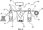
на фиг.2 схематично показан один из вариантов осуществления изобретения;figure 2 schematically shows one embodiment of the invention;
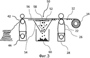
на фиг.3 схематично показан один из вариантов осуществления изобретения.figure 3 schematically shows one embodiment of the invention.
ОПИСАНИЕ ПРЕДПОЧТИТЕЛЬНЫХ ВАРИАНТОВ DESCRIPTION OF PREFERRED EMBODIMENTS
ОСУЩЕСТВЛЕНИЯ ИЗОБРЕТЕНИЯDETAILED DESCRIPTION OF THE INVENTION
Со ссылкой на фиг.1, в одном из вариантов осуществления изобретения устройство 10 для очистки фильтрующей ткани 12 содержит первый опорный элемент 14, удерживающий моток использованной фильтрующей ткани, подлежащей очистке. Станция 16 очистки расположена смежно первому опорному элементу 14. Второй опорный элемент 18 для приема очищенной фильтрующей ткани 12 на второй ролик расположен с другой стороны станции очистки от первого опорного элемента. Устройство сбора, такое как камера 20 сбора, для приема материала, удаленного с грязной фильтрующей ткани, расположена между двумя опорными элементами 14, 18 внизу, где перемещается фильтрующая ткань. Материал, удаленный с грязной фильтрующей ткани и собираемый в устройстве сбора, здесь далее называется «отходы».With reference to FIG. 1, in one embodiment of the invention, the device 10 for cleaning the
Первый опорный элемент 14 удерживает ролик использованной фильтрующей ткани 12, предназначенной для очистки. Фильтрующая ткань 12 направляется с ролика через два направляющих ролика 22, которые направляют фильтрующую ткань через станцию 16 очистки. После прохождения через станцию 16 очистки фильтрующая ткань 12 собирается на втором опорном элементе 18. Второй опорный элемент 18 соединен с двигателем 24 посредством приводного ремня 26. При запуске двигателя 24 он заставляет вращаться второй опорный элемент 24 и, если фильтр соединен со вторым опорным элементом, тянет фильтрующую ткань от ролика грязной фильтрующей ткани 12 через станцию 16 очистки на второй опорный элемент 18. Направляющие ролики 22 также могут быть соединены со вторым двигателем 28 посредством приводного ремня 26. При запуске второго двигателя 28 он вращает нижний ролик пары направляющих роликов 22. Это приводит к стягиванию фильтрующей ткани 12 с ролика и перемещению фильтрующей ткани 12 в станцию 16 очистки.The
Устройство может содержать систему управления двигателем для управления скоростью двигателя и систему датчиков. Датчик располагают так, чтобы определять диаметр ролика очищенной фильтрующей ткани, хранимой на втором опорном элементе. Датчик может посылать сигнал на блок управления системы управления двигателем в зависимости от диаметра ролика чистой ткани. Блок управления регулирует скорость двигателя в зависимости от количества имеющейся чистой ткани для поддержания постоянной скорости ткани, перемещаемой через станцию очистки.The device may include an engine management system for controlling engine speed and a sensor system. The sensor is positioned so as to determine the diameter of the roller of the cleaned filter cloth stored on the second support element. The sensor can send a signal to the engine control unit control unit depending on the diameter of the clean cloth roller. The control unit adjusts the speed of the engine depending on the amount of clean tissue available to maintain a constant speed of tissue moving through the cleaning station.
Станция 16 очистки содержит устройство воздушного потока, такое как газовый компрессор 30 или любое аналогичное устройство, пригодное для обеспечения протекания газа 32 через фильтрующую ткань по мере перемещения фильтрующей ткани через станцию очистки 12 для удаления материала с фильтрующей ткани и направления его в устройство сбора. В одном из вариантов осуществления газ представляет собой воздух. В другом варианте осуществления газовый компрессор представляет собой воздушный компрессор. Газовый компрессор 30 выполнен с возможностью направления потока газа перпендикулярно перемещению фильтрующей ткани, так что сжатый газ проходит сверху от фильтрующей ткани с чистой стороны к стороне, на которую осаждался фильтруемый материал. Прилагаемое усилие газа достаточно для смещения материала, собранного на фильтре.The
В настоящем документе термин «материал» используется в широком смысле и обозначает любой материал, собранный на фильтрующей ткани и удаляемый согласно настоящему изобретению. Соответственно, материал может представлять собой или может содержать частицы, такие как твердые частицы, жидкие частицы или эмульсии или их сочетания. Например, материал может представлять собой или может содержать эмульсии и/или капли, существенно не смешивающиеся или только частично растворимые в воде, такие как масло и/или капли масла/воды.As used herein, the term “material” is used in a broad sense and refers to any material collected on filter cloth and disposed of in accordance with the present invention. Accordingly, the material may be or may contain particles, such as solid particles, liquid particles or emulsions, or combinations thereof. For example, the material may be or may contain emulsions and / or drops that are not substantially miscible or only partially soluble in water, such as oil and / or drops of oil / water.
Камера 20 сбора может представлять собой любой подходящий контейнер для удержания отходов, такой как мешок, сборник или коробку для последующей ликвидации, обработки и/или переработки отходов. Устройство сбора также может содержать направляющее устройство, такое как воронка 34, расположенное между камерой 20 и фильтрующей тканью 12, для вмещения потока отходов, падающего с ткани, и направления отходов в камеру. Пластины 36 образуют опорную поверхность с отверстием 38, через которое газовый компрессор продувает газ, направляя материал с фильтрующей ткани 12 в камеру 20.The
Размер фильтрующих тканей, используемых в промышленном оборудовании для обработки металлов, может иметь ширину до 3 м и более. Размер устройства зависит от применяемой фильтрующей ткани. Предпочтительно, чтобы газовый компрессор обеспечивал протекание газа по всей ширине фильтрующей ткани.The size of filter cloths used in industrial equipment for metal processing can have a width of up to 3 m or more. The size of the device depends on the filter cloth used. Preferably, the gas compressor allows gas to flow across the entire width of the filter cloth.
Ролик грязной фильтрующей ткани загружают в устройство, так чтобы при протягивании фильтрующей ткани 12 через станцию 16 очистки сторона фильтрующей ткани, на которую осажден материал, была повернута к камере 20 сбора. Исходный участок ткани протягивают от ролика использованной ткани через станцию очистки 12 и соединяют с роликом второго опорного элемента 18. Запускают двигатель 24, который вращает второй ролик, тянущий фильтр от первого ролика через станцию 16 очистки до второго ролика. По мере перемещения фильтрующей ткани на второй ролик датчик определяет диаметр ролика очищенной ткани и посылает сигнал на блок управления в зависимости от диаметра очищенной ткани. Блок управления изменяет скорость двигателя 24 для сохранения постоянной скорости перемещения ткани через станцию 16 очистки. Скорость двигателя меняется по мере перемещения ткани на второй ролик и увеличения диаметра ролика.The dirty filter cloth roller is loaded into the device so that when the
По мере перемещения фильтрующей ткани 12 через станцию 16 очистки приводят в действие газовый компрессор 30 и поток сжатого газа 32 направляют на область фильтрующей ткани 12, расположенную под компрессором и над отверстием 38 в пластинах 36. Работу двигателя осуществляют для гарантирования того, что скорость перемещения фильтрующей ткани через станцию очистки обеспечивает достаточное время воздействия потока газа из компрессора на область фильтрующей ткани для смещения отходов с ткани.As the
Поток газа 32 достаточно интенсивен для смещения материала с ткани 12, который затем может падать в камеру 20, где собираются и хранятся отходы для последующей ликвидации, обработки и/или переработки.The
На фиг.2 показан еще один вариант осуществления изобретения. Устройство содержит первый опорный элемент 14, удерживающий ролик использованной фильтрующей ткани 12, предназначенной для очистки. Станция 16 очистки расположена смежно первому опорному элементу 14. Устройство также содержит камеру 20 сбора для приема удаленного материала с использованной фильтрующей ткани 12.Figure 2 shows another embodiment of the invention. The device comprises a
Первый опорный элемент 14 удерживает ролик использованной фильтрующей ткани 12, предназначенной для очистки. Фильтрующая ткань 12 направляется с ролика через первый набор направляющих роликов 22, которые направляют фильтрующую ткань через станцию 16 очистки. После прохождения через станцию 16 очистки фильтрующую ткань 12 направляют через второй набор направляющих роликов 42 и очищенную ткань складывают для повторного применения. Второй набор роликов 42 приводится в действие посредством двигателя 44, расположенного под нижним роликом 42 и соединенного с нижним роликом посредством приводного ремня 26. Когда мотор 44 приведен в действие для вращения ролика, это побуждает ролик тянуть фильтрующую ткань 12 от первого ролика через первый набор направляющих роликов 22 и через станцию 16 очистки, а затем через второй набор ведущих роликов 42, где затем можно собирать очищенную ткань. Первый набор ведущих роликов 22 может быть соединен со вторым двигателем 28 для способствования протягиванию фильтрующей ткани 12 от ролика и ее направлению через станцию 16 очистки.The
Как описано выше, станция 16 очистки содержит газовый компрессор 30, выполненный с возможностью обеспечения протекания газа 32 через фильтрующую ткань 12 по мере протягивания фильтрующей ткани 12 через станцию 16 очистки. Газовый компрессор 30 направляет газ сверху фильтрующей ткани и через ткань с чистой стороны к использованной стороне. Усилие газа достаточно для смещения материала, собранного с фильтрующей ткани 12, и направления материала в камеру 20 сбора.As described above, the cleaning
Воронка 34 расположена между камерой и фильтрующей тканью для вмещения потока отходов, падающих с ткани, и направления отходов в камеру 20. Воронка 34 содержит наклонные стенки и пластины 36, образующие отверстие 38, через которое газовый компрессор 30 продувает газ.A
Ролик использованной фильтрующей ткани 12 загружают в устройство 40. При загрузке ролика использованной фильтрующей ткани 12 в устройство его располагают так, что при втягивании фильтрующей ткани 12 в станцию 16 очистки грязная сторона ткани 12 обращена вниз к камере 20 сбора. Начальный участок ткани тянут от первого ролика и через первый набор направляющих роликов 22, станцию 16 очистки и затем через второй набор направляющих роликов 42. Двигатель 44 приводят в движение, что побуждает вращение ролика 42, тянущего фильтр с первого ролика через первый набор направляющих роликов 22 и станцию очистки, а затем через вторые направляющие ролики 42 для сбора из устройства.The roller of the used
По мере протягивания фильтрующей ткани 12 через станцию 16 очистки запускают газовый компрессор 30, который продувает газ через область фильтрующей ткани, расположенную под газовым компрессором 30 и над камерой 20. Двигатель приводят в действие для гарантирования того, что скорость перемещения фильтрующей ткани через станцию очистки обеспечивает достаточное время воздействия газа из компрессора на область фильтрующей ткани для смещения отходов с ткани.As the
На фиг.3 показан один из вариантов осуществления изобретения, в котором станция 50 очистки содержит устройство 52 втягивания. По мере перемещения фильтрующей ткани 12 через станцию 50 очистки материал с фильтрующей ткани 12 может быть втянут с фильтрующей ткани 12. Устройство 52 втягивания может быть расположено в воронке 54 под пластинами 56, образующими отверстие 58, через которое материал может падать с фильтрующей ткани 12 в камеру 60. Устройство 52 втягивания создает поток газа 62, который втягивает материал с фильтрующей ткани 12 по мере ее прохождения через отверстие 58. Сила втягивания достаточна для вытягивания материала с фильтрующей ткани 12, так что он попадает в камеру 60 сбора, откуда отходы могут быть ликвидированы, удалены или повторно использованы.Figure 3 shows one embodiment of the invention in which the cleaning
Двигатели 44 и 28 приводят в действие для гарантирования того, что скорость протягивания фильтрующей ткани 12 через станцию 50 очистки обеспечивает достаточное время для воздействия газа из устройства 52 втягивания на область фильтрующей ткани для втягивания материала с ткани в камеру 60 сбора.
Щетки и/или скребки могут быть расположены на устройстве для высвобождения материала с фильтрующей ткани до обработки фильтрующей ткани посредством втягивания устройством сжатого газа. Щетки и скребки способствуют смещению материала и частично удаляют материал, собранный на ткани, что облегчает удаление материала с фильтрующей ткани посредством устройства сжатого газа или устройства втягивания.Brushes and / or scrapers can be located on the device to release material from the filter cloth before processing the filter cloth by drawing in the compressed gas. Brushes and scrapers contribute to the displacement of the material and partially remove the material collected on the fabric, which facilitates the removal of material from the filter fabric by means of a compressed gas device or a retraction device.
Щетки могут быть расположены после первого набора направляющих роликов, так что щетина щеток взаимодействует с материалом, осажденным на фильтрующей ткани. Скребок может быть расположен так, чтобы лезвие скребка взаимодействовало с материалом, осажденным на фильтрующей ткани.Brushes can be located after the first set of guide rollers, so that the brush bristles interact with the material deposited on the filter cloth. The scraper can be positioned so that the scraper blade interacts with the material deposited on the filter cloth.
Дополнительные варианты настоящего изобретения определены в следующих пронумерованных пунктах:Additional embodiments of the present invention are defined in the following numbered paragraphs:
1. Устройство для очистки фильтрующей ткани, содержащее:1. A device for cleaning filter cloth, containing:
опорный элемент для удержания подачи фильтрующей ткани;support element for holding the supply of filter cloth;
станцию очистки, содержащую устройство воздушного потока и опорную поверхность, образующую отверстие;a cleaning station comprising an air flow device and a support surface forming an opening;
устройство перемещения для перемещения фильтрующей ткани с опорного элемента через отверстие в станцию очистки; иa moving device for moving the filter fabric from the support element through an opening to the cleaning station; and
камеру сбора, расположенную под отверстием для приема частиц, удаленных с фильтрующей ткани;a collection chamber located under the hole for receiving particles removed from the filter cloth;
при этом устройство воздушного потока выполнено с возможностью обеспечения протекания воздуха через область фильтрующей ткани, расположенную над отверстием, для удаления частиц с фильтрующей ткани и направления их в камеру сбора.however, the air flow device is configured to allow air to flow through the area of the filter fabric located above the hole to remove particles from the filter fabric and direct them to the collection chamber.
2. Устройство по п.1, в котором устройство потока воздуха представляет собой устройство продувания воздуха, расположенное над опорной поверхностью и выполненное с возможностью продувания воздуха через фильтрующую ткань и в отверстие.2. The device according to claim 1, in which the air flow device is an air purge device located above the supporting surface and configured to purge air through the filter cloth and into the hole.
3. Устройство по п.1, в котором устройство потока воздуха представляет собой устройство втягивания воздуха, расположенное под опорной поверхностью и выполненное с возможностью втягивания воздуха через фильтрующую ткань и отверстие.3. The device according to claim 1, in which the air flow device is an air retraction device located under the supporting surface and configured to draw air through the filter cloth and the hole.
4. Устройство по любому из пп.1-3, содержащее второй опорный элемент, на котором можно хранить очищенную фильтрующую ткань после ее перемещения вдоль станции очистки.4. The device according to any one of claims 1 to 3, containing a second support element, on which you can store the cleaned filter cloth after moving it along the cleaning station.
5. Устройство по п.4, содержащее систему управления устройством перемещения, содержащую систему датчиков для определения количества очищенной фильтрующей ткани, хранимой на втором опорном элементе.5. The device according to claim 4, containing a control system for the moving device, comprising a system of sensors for determining the amount of cleaned filter cloth stored on the second supporting element.
6. Устройство по любому из пп.1-5, дополнительно содержащее щетку, расположенную перед устройством продувания воздуха и выполненную с возможностью чистки щеткой частиц с поверхности ткани.6. The device according to any one of claims 1 to 5, further comprising a brush located in front of the air purge device and configured to brush particles from the surface of the fabric with a brush.
7. Устройство по любому из пп.1-6, содержащее воронку, расположенную под отверстием для направления частиц с ткани в камеру.7. The device according to any one of claims 1 to 6, containing a funnel located under the hole for directing particles from the tissue into the chamber.
8. Устройство по любому из пп.1-7, в котором опорная поверхность содержит расположенные на расстоянии пластины, образующие отверстие.8. The device according to any one of claims 1 to 7, in which the supporting surface comprises spaced apart plates forming an opening.
9. Способ очистки фильтрующей ткани, включающий в себя этапы, на которых:9. A method of cleaning a filter cloth, comprising the steps of:
пропускают использованную фильтрующую ткань через станцию очистки, содержащую устройство воздушного потока и опорную поверхность, образующую отверстие;passing the used filter cloth through a cleaning station comprising an air flow device and a support surface forming an opening;
осуществляют работу устройства воздушного потока для направления потока воздуха через область ткани над отверстием; иcarry out the operation of the air flow device to direct the air flow through the tissue area above the hole; and
собирают частицы, удаленные с ткани потоком воздуха, в камере под отверстием.collect particles removed from the tissue by a stream of air in a chamber under the hole.
10. Способ по п.9, в котором этап осуществления работы устройства воздушного потока включает в себя этап, на котором продувают воздух через ткань.10. The method according to claim 9, in which the stage of operation of the air flow device includes a step on which air is blown through the fabric.
11. Способ по п.9, в котором этап осуществления работы устройства воздушного потока включает в себя этап, на котором втягивают воздух через фильтрующую ткань.11. The method according to claim 9, in which the stage of operation of the air flow device includes a step on which air is drawn in through the filter cloth.
12. Способ по любому из пп.9-11, дополнительно включающий в себя этап, на котором чистят щеткой ткань для удаления частиц с ткани до прохождения ткани через станцию очистки.12. The method according to any one of claims 9 to 11, further comprising the step of brushing the fabric to remove particles from the fabric before the fabric passes through the cleaning station.
13. Способ по любому из пп.9-12, включающий в себя этап, на котором прокатывают фильтрующую ткань через держатель после прохождения через станцию очистки.13. The method according to any one of claims 9 to 12, comprising the step of rolling the filter cloth through the holder after passing through the cleaning station.
14. Способ по любому из пп.9-12, включающий в себя этап, на котором складывают фильтрующую ткань после прохождения через станцию очистки.14. The method according to any one of claims 9 to 12, comprising the step of folding the filter cloth after passing through the cleaning station.
15. Способ по любому из пп.9-14, включающий в себя этапы, на которых используют устройство, описанное в любом из пп.1-8.15. The method according to any one of claims 9 to 14, comprising the steps of using the device described in any of claims 1 to 8.
Хотя изобретение описано в виде примера со ссылкой на конкретные варианты осуществления изобретения, могут быть внесены другие изменения в рамках изобретения. Различные изменения и варианты изобретения без выхода за рамки и сущность изобретения очевидны для специалиста. Хотя изобретение описано в связи с конкретными предпочтительными вариантами осуществления, следует понимать, что заявленное изобретение не должно быть ненадлежащим образом ограниченно до таких конкретных вариантов осуществления. Действительно, предполагается, что различные изменения описанных вариантов осуществления изобретения, очевидные для экспертов в соответствующем уровне или соответствующих областях техники, находятся в рамках следующей формулы изобретения.Although the invention has been described by way of example with reference to specific embodiments of the invention, other changes within the scope of the invention may be made. Various changes and variations of the invention without departing from the scope and essence of the invention are obvious to a person skilled in the art. Although the invention has been described in connection with specific preferred embodiments, it should be understood that the claimed invention should not be inappropriately limited to such specific embodiments. Indeed, it is contemplated that various changes to the described embodiments of the invention that are obvious to experts at the appropriate level or related technical fields are within the scope of the following claims.
Claims (14)
станцию очистки, содержащую устройство газового потока и опорную поверхность, образующую отверстие; и
отдельное устройство сбора, расположенное под отверстием, для приема материала, удаленного с фильтрующей ткани:
при этом устройство газового потока выполнено с возможностью обеспечения протекания газа через область фильтрующей ткани, расположенной над отверстием, для удаления материала с фильтрующей ткани и направления его в отдельное устройство сбора.1. A device for cleaning filter cloth, containing:
a cleaning station comprising a gas flow device and a support surface forming an opening; and
a separate collection device located under the hole for receiving material removed from the filter cloth:
however, the gas flow device is configured to allow gas to flow through the area of the filter fabric located above the hole to remove material from the filter fabric and direct it to a separate collection device.
пропускают использованную фильтрующую ткань через станцию очистки, содержащую устройство газового потока и опорную поверхность, образующую отверстие;
осуществляют работу устройства газового потока для направления потока газа через область ткани над отверстием; и
собирают материал, удаленный с ткани газовым потоком, в отдельной камере под отверстием.10. A method for cleaning filter cloth, comprising the steps of:
passing the used filter cloth through a cleaning station comprising a gas flow device and a support surface forming an opening;
operating the gas flow device to direct the gas flow through the tissue region above the hole; and
collect material removed from the fabric by gas flow in a separate chamber under the hole.
Applications Claiming Priority (3)
| Application Number | Priority Date | Filing Date | Title |
|---|---|---|---|
| GB1003202.7 | 2010-02-25 | ||
| GBGB1003202.7A GB201003202D0 (en) | 2010-02-25 | 2010-02-25 | Method and apparatus for cleaning filters |
| PCT/GB2011/000257 WO2011104511A1 (en) | 2010-02-25 | 2011-02-24 | Method and apparatus for cleaning filters |
Publications (2)
| Publication Number | Publication Date |
|---|---|
| RU2012141023A RU2012141023A (en) | 2014-04-10 |
| RU2559503C2 true RU2559503C2 (en) | 2015-08-10 |
Family
ID=42125631
Family Applications (1)
| Application Number | Title | Priority Date | Filing Date |
|---|---|---|---|
| RU2012141023/05A RU2559503C2 (en) | 2010-02-25 | 2011-02-24 | Method and device for cleaning of filters |
Country Status (11)
| Country | Link |
|---|---|
| US (1) | US20130068252A1 (en) |
| EP (1) | EP2539037A1 (en) |
| JP (1) | JP2013520310A (en) |
| KR (1) | KR20130050913A (en) |
| CN (1) | CN102985151B (en) |
| AU (1) | AU2011219577B2 (en) |
| BR (1) | BR112012021578A2 (en) |
| CA (1) | CA2828184A1 (en) |
| GB (2) | GB201003202D0 (en) |
| RU (1) | RU2559503C2 (en) |
| WO (1) | WO2011104511A1 (en) |
Families Citing this family (11)
| Publication number | Priority date | Publication date | Assignee | Title |
|---|---|---|---|---|
| CN103949098B (en) * | 2014-05-05 | 2016-08-31 | 孙伟春 | Filter cloth filter membrane is removed the automatic filter pressing of formula and is extracted collection integrated module |
| ITUA20161836A1 (en) * | 2016-03-21 | 2017-09-21 | C M Produzione S R L | FILTRATION DEVICE FOR EXTRUSION-FREE EXTRUSION PROCESSES. |
| CN105903250B (en) * | 2016-06-13 | 2018-04-13 | 李挺树 | There is filter cloth vacuum suction filter filter cloth pull of vacuum washing system |
| CN106390552A (en) * | 2016-11-18 | 2017-02-15 | 江铜华北(天津)铜业有限公司 | Filter cloth recovering device and copper rod continuous casting and rolling production system applying same |
| CN108543350A (en) * | 2016-12-27 | 2018-09-18 | 苏州欣航微电子有限公司 | A kind of brushing device of air-purifying net |
| CN107281818A (en) * | 2017-08-16 | 2017-10-24 | 李飞 | A kind of Alveolate activated carbon screen pack brushing device |
| CN108246677A (en) * | 2018-01-09 | 2018-07-06 | 清远市齐力合成革有限公司 | A kind of automatic bristle fur-absorbing device |
| CN108525396B (en) * | 2018-04-28 | 2019-08-27 | 江苏灵氟隆环境工程有限公司 | An automatic filter cloth cleaning device |
| CN108854269A (en) * | 2018-07-16 | 2018-11-23 | 江苏鼎盛滤袋有限公司 | A kind of filter cloth filter bag cleaning device and its application method |
| CN110899301B (en) * | 2019-12-02 | 2021-01-08 | 烟台腾泰环保建材有限公司 | Construction waste classification and recovery method |
| CN114146920B (en) * | 2021-12-02 | 2023-03-07 | 绍兴泓润纺织科技有限公司 | Knitting waste collection processing apparatus |
Citations (5)
| Publication number | Priority date | Publication date | Assignee | Title |
|---|---|---|---|---|
| GB925874A (en) * | 1960-02-03 | 1963-05-08 | Ozonair Engineering Company Lt | Improvements in gas filters |
| US3337898A (en) * | 1964-09-28 | 1967-08-29 | Itt | Vibrating vacuum head |
| SU1724326A1 (en) * | 1990-06-04 | 1992-04-07 | Ленинградский институт текстильной и легкой промышленности им.С.М.Кирова | Gas filter |
| RU2089016C1 (en) * | 1995-12-20 | 1997-08-27 | Институт химии и технологии редких элементов и минерального сырья Кольского научного центра РАН | Device for separating compact material from article gauze base |
| DE202007004536U1 (en) * | 2007-03-28 | 2007-06-28 | Leipoldt, Matthias, Dipl.-Ing. | Belt filter for separation of solids from liquids uses minimal filtration area by provision of vacuum slots below feed area |
Family Cites Families (12)
| Publication number | Priority date | Publication date | Assignee | Title |
|---|---|---|---|---|
| US3356565A (en) * | 1964-08-13 | 1967-12-05 | Owens Corning Fiberglass Corp | Waste wash water and waste binder reuse system and apparatus for mineral fiber forming process |
| JPS5811021A (en) * | 1981-07-10 | 1983-01-21 | Daido Steel Co Ltd | Reproducing device of air filter |
| GB2106270B (en) * | 1981-09-17 | 1985-10-02 | Emi Ltd | Tape transport control systems |
| US4521230A (en) * | 1984-07-26 | 1985-06-04 | Strong John C | Self-cleaning furnace filter construction |
| JPH03131314A (en) * | 1989-10-17 | 1991-06-04 | Sankyo Giken Kogyo Kk | Method and apparatus for washing and regenerating sheet like filter material |
| JPH09122425A (en) * | 1995-11-07 | 1997-05-13 | Daiwa Seisakusho:Kk | Cleaning device for filter |
| US6101669A (en) * | 1998-06-04 | 2000-08-15 | Emerson Electric Co. | Wet/dry vacuum |
| JP3482879B2 (en) * | 1998-07-27 | 2004-01-06 | 松下電工株式会社 | Suction box |
| JP2001129332A (en) * | 1999-11-10 | 2001-05-15 | Taisei Corp | Automatic filter cleaning device |
| US20070012188A1 (en) * | 2005-07-05 | 2007-01-18 | Tandon Hans P | Apparatus and method for removing contaminants from a gas stream |
| US20090242469A1 (en) * | 2008-04-01 | 2009-10-01 | Gerry Calabrese | Filter Assembly for Cleaning Fluids by Way of an Indexing Cloth Filter |
| US7794605B2 (en) * | 2008-06-19 | 2010-09-14 | Flsmidth A/S | Horizontal belt filter with vacuum pan alignment |
-
2010
- 2010-02-25 GB GBGB1003202.7A patent/GB201003202D0/en not_active Ceased
-
2011
- 2011-02-24 GB GB1103225.7A patent/GB2478197B/en not_active Expired - Fee Related
- 2011-02-24 CN CN201180020845.1A patent/CN102985151B/en not_active Expired - Fee Related
- 2011-02-24 BR BR112012021578A patent/BR112012021578A2/en not_active IP Right Cessation
- 2011-02-24 AU AU2011219577A patent/AU2011219577B2/en not_active Ceased
- 2011-02-24 JP JP2012554408A patent/JP2013520310A/en active Pending
- 2011-02-24 EP EP11706905A patent/EP2539037A1/en not_active Withdrawn
- 2011-02-24 RU RU2012141023/05A patent/RU2559503C2/en not_active IP Right Cessation
- 2011-02-24 CA CA2828184A patent/CA2828184A1/en not_active Abandoned
- 2011-02-24 KR KR1020127025127A patent/KR20130050913A/en not_active Withdrawn
- 2011-02-24 WO PCT/GB2011/000257 patent/WO2011104511A1/en not_active Ceased
-
2012
- 2012-08-22 US US13/591,668 patent/US20130068252A1/en not_active Abandoned
Patent Citations (5)
| Publication number | Priority date | Publication date | Assignee | Title |
|---|---|---|---|---|
| GB925874A (en) * | 1960-02-03 | 1963-05-08 | Ozonair Engineering Company Lt | Improvements in gas filters |
| US3337898A (en) * | 1964-09-28 | 1967-08-29 | Itt | Vibrating vacuum head |
| SU1724326A1 (en) * | 1990-06-04 | 1992-04-07 | Ленинградский институт текстильной и легкой промышленности им.С.М.Кирова | Gas filter |
| RU2089016C1 (en) * | 1995-12-20 | 1997-08-27 | Институт химии и технологии редких элементов и минерального сырья Кольского научного центра РАН | Device for separating compact material from article gauze base |
| DE202007004536U1 (en) * | 2007-03-28 | 2007-06-28 | Leipoldt, Matthias, Dipl.-Ing. | Belt filter for separation of solids from liquids uses minimal filtration area by provision of vacuum slots below feed area |
Also Published As
| Publication number | Publication date |
|---|---|
| RU2012141023A (en) | 2014-04-10 |
| WO2011104511A1 (en) | 2011-09-01 |
| CN102985151B (en) | 2015-08-05 |
| KR20130050913A (en) | 2013-05-16 |
| GB2478197A (en) | 2011-08-31 |
| AU2011219577A1 (en) | 2012-10-18 |
| BR112012021578A2 (en) | 2016-10-25 |
| EP2539037A1 (en) | 2013-01-02 |
| GB201103225D0 (en) | 2011-04-13 |
| AU2011219577B2 (en) | 2015-03-12 |
| CN102985151A (en) | 2013-03-20 |
| US20130068252A1 (en) | 2013-03-21 |
| JP2013520310A (en) | 2013-06-06 |
| CA2828184A1 (en) | 2011-09-01 |
| GB201003202D0 (en) | 2010-04-14 |
| GB2478197B (en) | 2012-02-01 |
Similar Documents
| Publication | Publication Date | Title |
|---|---|---|
| RU2559503C2 (en) | Method and device for cleaning of filters | |
| JP5444144B2 (en) | Cooling lubricant processing equipment | |
| CA2928448C (en) | Mat cleaning and drying apparatus and method | |
| JP6865938B1 (en) | Impurity remover | |
| KR101000371B1 (en) | Oil mist collector | |
| JP7682132B2 (en) | Drum-type filtration device using strip-shaped filter media | |
| JP5349065B2 (en) | Coolant processing equipment | |
| FR3036635A1 (en) | PROCESS FOR TREATING DUST REMOVED FROM A SURFACE BY A TOOL AND EQUIPMENT FOR CARRYING OUT SAID METHOD | |
| US6578714B2 (en) | Mobile washer with fluid reclamation system | |
| KR101058200B1 (en) | Grinding Oil Filter | |
| JP2019141982A (en) | Coolant processing apparatus | |
| JP6635453B1 (en) | Sludge removal device | |
| KR100779709B1 (en) | Floating sludge removal device of degreasing container | |
| KR101992435B1 (en) | Micro chip separator using filter drum and scraper | |
| JP2006305430A (en) | Continuous filtering device | |
| KR100823609B1 (en) | Swapping removal device of steel plate degreasing equipment | |
| JP2000354712A (en) | Treatment of industrial oil and treating device | |
| CN218283196U (en) | Aluminum plate cold roll grinds dewatering equipment | |
| KR102201423B1 (en) | High efficiency cutting oil filtering device | |
| JP2000325709A (en) | Washing apparatus for filter for electric discharge machine | |
| KR20170101419A (en) | cutting oil collecting device in cutting sludge | |
| GB2306895A (en) | Filtration Apparatus | |
| JPH067810U (en) | A mechanism for cutting used filter paper of the contaminated liquid filter | |
| JPH06230185A (en) | Decontamination method and device for radioactive waste | |
| JP2007046375A (en) | Coarse screen scraping device for running water trough |
Legal Events
| Date | Code | Title | Description |
|---|---|---|---|
| MM4A | The patent is invalid due to non-payment of fees |
Effective date: 20160225 |