RU2551742C2 - Pouring nozzle and mounting assembly including it - Google Patents
Pouring nozzle and mounting assembly including it Download PDFInfo
- Publication number
- RU2551742C2 RU2551742C2 RU2012112621/02A RU2012112621A RU2551742C2 RU 2551742 C2 RU2551742 C2 RU 2551742C2 RU 2012112621/02 A RU2012112621/02 A RU 2012112621/02A RU 2012112621 A RU2012112621 A RU 2012112621A RU 2551742 C2 RU2551742 C2 RU 2551742C2
- Authority
- RU
- Russia
- Prior art keywords
- axis
- plate
- pipe
- casting
- outlet openings
- Prior art date
Links
Images
Classifications
-
- B—PERFORMING OPERATIONS; TRANSPORTING
- B22—CASTING; POWDER METALLURGY
- B22D—CASTING OF METALS; CASTING OF OTHER SUBSTANCES BY THE SAME PROCESSES OR DEVICES
- B22D41/00—Casting melt-holding vessels, e.g. ladles, tundishes, cups or the like
- B22D41/14—Closures
- B22D41/22—Closures sliding-gate type, i.e. having a fixed plate and a movable plate in sliding contact with each other for selective registry of their openings
-
- B—PERFORMING OPERATIONS; TRANSPORTING
- B22—CASTING; POWDER METALLURGY
- B22D—CASTING OF METALS; CASTING OF OTHER SUBSTANCES BY THE SAME PROCESSES OR DEVICES
- B22D41/00—Casting melt-holding vessels, e.g. ladles, tundishes, cups or the like
- B22D41/50—Pouring-nozzles
Abstract
Description
Настоящее изобретение относится к огнеупорному элементу, который используется для непрерывной разливки жидкой стали из верхней металлургической емкости в нижнюю металлургическую емкость.The present invention relates to a refractory element that is used for continuous casting of molten steel from an upper metallurgical vessel to a lower metallurgical vessel.
В соответствии с конкретным примером осуществления изобретения стакан используется для разливки жидкой стали из распределительного резервуара (иногда также именуемого промежуточным разливочным устройством) в литейную форму или изложницу (иногда также именуемую кокилем).According to a specific embodiment of the invention, a beaker is used for casting molten steel from a distribution tank (sometimes also referred to as an intermediate filling device) into a mold or mold (sometimes also referred to as a chill mold).
При непрерывной разливке стали из промежуточного разливочного устройства в изложницу разливочный стакан используется для защиты жидкой стали от химического воздействия окружающей атмосферы и обеспечения тепловой изоляции стали во время передачи из верхней емкости в нижнюю емкость. Эти стаканы приблизительно цилиндрической формы, неразъемные, имеющие верхний конец, обычно снабженный коническим впускным отверстием, которое расположено рядом с днищем верхней емкости. В стаканах прошито сквозное проходное отверстие, образующее разливочный канал, по которому жидкая сталь может стекать в нижний конец стакана, погруженного в изложницу. В большинстве случаев нижний конец стакана закрыт или как минимум снабжен сужением для ограничения вихревого потока струи стали, и сталь выходит в изложницу главным образом через боковые отверстия (также именуемые выпускными отверстиями), которыми снабжен нижний конец стакана. В контексте настоящего изобретения термин «закрытый» нижний конец стакана используется для обозначения либо стаканов, которые действительно закрыты на нижнем конце, либо просто имеющие сужение. В случае разливки стали в виде плоских заготовок, например слябов, используется изложница, представляющая собой литейную форму без днища, с четырьмя боковыми стенками, обычно выполненными из меди, с водяным охлаждением, попарно параллельными, которая имеет поперечное сечение примерно прямоугольной формы, соответствующее приблизительно ширине и толщине сляба. Длина изложницы значительно больше ее ширины. Боковые отверстия в нижней части стакана обычно расположены симметрично относительно друг друга для обеспечения гомогенного потока в изложницу. Кроме того, боковые отверстия никогда не направлены точно на длинные стенки изложницы, которые к тому же расположены ближе всего к стакану, без которого жидкая сталь, выходящая из промежуточного разливочного устройства, и, следовательно, все еще сохраняющая высокую температуру, контактировала бы напрямую с длинными стенками, что привело бы к чрезмерному нагреву и, через некоторое время, к плавлению медных стенок. В результате произошло бы вытекание стали с катастрофическими последствиями и для установки, и для персонала. Напротив, боковые отверстия стакана направлены на короткие стенки изложницы, удаленные; таким образом сталь, выходящая из промежуточного разливочного устройства, успевает остыть в контакте с ранее вылитой сталью до того, как достигнет этих стенок.In the continuous casting of steel from an intermediate casting device into a mold, a casting cup is used to protect liquid steel from the chemical effects of the surrounding atmosphere and to provide thermal insulation of the steel during transfer from the upper tank to the lower tank. These glasses are approximately cylindrical in shape, one-piece, having an upper end, usually provided with a conical inlet that is located near the bottom of the upper tank. A through hole is sewn into the glasses, forming a casting channel through which liquid steel can drain into the lower end of the glass immersed in the mold. In most cases, the lower end of the cup is closed or at least constricted to limit the vortex flow of the steel stream, and the steel enters the mold mainly through the side openings (also called outlet openings) that the bottom end of the cup is provided with. In the context of the present invention, the term “closed” lower end of a cup is used to mean either cups that are actually closed at the lower end, or simply having a narrowing. In the case of casting steel in the form of flat billets, for example slabs, a mold is used, which is a casting mold without a bottom, with four side walls, usually made of copper, with water cooling, paired in parallel, which has a cross section of approximately rectangular shape, corresponding to approximately width and the thickness of the slab. The length of the mold is significantly greater than its width. Side openings in the lower part of the glass are usually located symmetrically relative to each other to ensure a homogeneous flow into the mold. In addition, the lateral openings are never directed exactly at the long walls of the mold, which are also located closest to the glass, without which the molten steel leaving the intermediate casting device, and therefore still retaining high temperature, would directly contact long walls, which would lead to excessive heating and, after some time, to the melting of copper walls. As a result, steel would leak with catastrophic consequences for both the installation and the personnel. On the contrary, the side openings of the glass are directed to the short walls of the mold removed; thus, the steel leaving the intermediate casting device has time to cool in contact with the previously cast steel before it reaches these walls.
Подобные разливочные стаканы являются быстроизнашивающимися деталями, работающими в сильнонапряженном состоянии до такой степени, что срок их службы может ограничивать продолжительность разливки. В частности, такие стаканы могут закупориваться отложениями из оксида алюминия, подвергаться эрозии под действием особенно коррозионного шлака или сорта стали, растрескиваться под действием термического или механического удара. Поэтому с 1980-х годов начались разработки устройства для ввода и замены стаканов.Such pouring glasses are wearing parts that work in a highly stressed state to such an extent that their service life may limit the duration of the casting. In particular, such glasses can become clogged with alumina deposits, undergo erosion under the influence of especially corrosive slag or steel grades, and crack under the influence of thermal or mechanical shock. Therefore, since the 1980s, the development of a device for introducing and replacing glasses began.
В этих устройствах погружной разливочный стакан, до того времени цельный и проходящий от днища промежуточного разливочного устройства до центра изложницы, заменяется на сборочный узел, включающий внутренний стакан (соответствующий верхней части погружного разливочного стакана), по которому сталь передается через днище промежуточного разливочного устройства, и разливочный стакан (соответствующий нижней части погружного разливочного стакана) для подачи стали в изложницу. Как правило, внутренний стакан и разливочный стакан выполнены как одно целое, но могут также представлять собой узел, например, из плиты и трубы. Плита может быть также отлита вокруг готовой трубы. В положении разливки разливочные каналы внутреннего стакана и разливочного стакана сообщаются. Нижний конец внутреннего стакана состоит из плиты, снабженной сопловым отверстием, и которая может герметически накладываться на другую плиту, также снабженную дроссельным отверстием, составляющую верхний конец разливочного стакана. Эти две плиты обеспечивают, во-первых, герметичность соединения между двумя стаканами и, во-вторых, скольжение разливочного стакана из резервного положения в положение разливки. Упомянутые плиты обычно имеют прямоугольную форму, чтобы обеспечивалось их скольжение в направляющей системе. В контексте настоящего описания ссылка будет сделана на эту общую прямоугольную форму, даже если на практике форма плиты будет отклоняться от указанной формы, например, если у нее будут скругленные или усеченные углы. Во всех случаях плита будет ограничиваться прямоугольником, у которого четыре стороны пересекают друг друга под прямым углом, а противоположные стороны попарно параллельны. Между прочим, следует отметить, что разливочный стакан скользит в направляющих системах в направлении, параллельном паре сторон, которое также соответствует направлению, заданному осью, проходящей по центру тяжести боковых отверстий (ось выпускных отверстий). Следует также отметить, что, в некоторых случаях, боковые отверстия стакана смещены преднамеренно так, чтобы они не были точно ориентированы на короткие стенки изложницы. Например, ось выпускных отверстий может быть смещена на угол вплоть до 25°, чтобы обеспечивалась циркуляция стали в изложнице для улучшения гомогенности отливки. Устройство для ввода и замены стаканов может быть также смещено во избежание возмущающего воздействия в этом устройстве. В том случае, когда нужно удерживать ось выпускных отверстий строго параллельно оси изложницы, необходимо сместить эту ось по отношению к направлению скольжения в направляющей системе. В контексте настоящего изобретения, когда направление определено относительно оси выпускных отверстий, следует иметь в виду, что это направление может изменяться от -25° до +25°. Таким образом, когда речь идет о направлении, параллельном оси выпускных отверстий, необходимо понимать, что это направление параллельно, в пределах 25°, оси выпускных отверстий.In these devices, the submersible casting cup, until then solid and extending from the bottom of the intermediate casting device to the center of the mold, is replaced by an assembly comprising an inner cup (corresponding to the upper part of the submersible casting cup) through which steel is transferred through the bottom of the intermediate casting device, and casting cup (corresponding to the bottom of the submersible casting cup) for feeding steel into the mold. As a rule, the inner glass and the pouring glass are made as a whole, but can also be a unit, for example, from a plate and a pipe. A plate may also be cast around the finished pipe. In the casting position, the casting channels of the inner cup and the casting cup are communicated. The lower end of the inner glass consists of a plate provided with a nozzle hole, and which can be hermetically superimposed on another plate, also equipped with a throttle hole, making up the upper end of the casting glass. These two plates provide, firstly, the tightness of the connection between the two glasses and, secondly, the sliding of the casting glass from the backup position to the casting position. Said slabs are usually rectangular in shape so that they slide in the guide system. In the context of the present description, reference will be made to this general rectangular shape, even if in practice the shape of the plate deviates from the specified shape, for example, if it has rounded or truncated corners. In all cases, the plate will be limited to a rectangle in which four sides intersect each other at a right angle, and the opposite sides are parallel in pairs. Incidentally, it should be noted that the pouring cup slides in the guide systems in a direction parallel to the pair of sides, which also corresponds to the direction given by the axis passing through the center of gravity of the side openings (axis of the outlet openings). It should also be noted that, in some cases, the side openings of the beaker are deliberately offset so that they are not accurately oriented towards the short walls of the mold. For example, the axis of the outlet openings can be offset up to 25 ° so that the steel in the mold is circulated to improve the homogeneity of the casting. The device for introducing and replacing glasses can also be biased to avoid disturbance in this device. In the case when it is necessary to keep the axis of the outlet openings strictly parallel to the axis of the mold, it is necessary to shift this axis with respect to the direction of sliding in the guide system. In the context of the present invention, when the direction is determined relative to the axis of the outlets, it should be borne in mind that this direction can vary from -25 ° to + 25 °. Thus, when it comes to a direction parallel to the axis of the outlet, it must be understood that this direction is parallel, within 25 °, of the axis of the outlet.
В установке, в которой используются упомянутые устройства для введения и замены стаканов, разливка выполняется через внутренний стакан и первый разливочный стакан, проходные отверстия которых соединяются. При необходимости замены разливочного стакана в положении разливки устройство перемещает новый разливочный стакан, находившийся до этого в резервном положении, по системе направляющих, включающих направляющие рельсы, в положение разливки. Во время этого скольжения новый разливочный стакан замещает заменяемый разливочный стакан. Во время скольжения плита, образующая верхний конец разливочного стакана, устанавливается на одной линии с разливочным каналом внутреннего стакана и перекрывает его. Такое устройство представлено в Европейском патенте ЕР-В1-192019. Это устройство полностью удовлетворяет требованиям рынка и существенно увеличивает продолжительность циклов разливки.In an installation in which said devices for introducing and replacing glasses are used, the casting is carried out through the inner glass and the first pouring glass, the passage openings of which are connected. If it is necessary to replace the nozzle in the pouring position, the device moves the new nozzle, which was previously in the backup position, along the guide system including the guide rails to the pouring position. During this slide, a new casting cup replaces the replaceable casting cup. During sliding, the plate forming the upper end of the casting cup is installed in line with the casting channel of the inner cup and overlaps it. Such a device is presented in European patent EP-B1-192019. This device fully meets the requirements of the market and significantly increases the duration of casting cycles.
В большинстве случаев регулирование потока разливаемой стали и, в частности, прерывание процесса в конце цикла разливки достигается посредством стопорного стержня, который приводится в действие из верхней части промежуточного разливочного устройства, тело которого проходит через ванну с жидкой сталью, а закругленный конец предназначен для перекрытия впускного отверстия внутреннего стакана.In most cases, regulation of the flow of cast steel and, in particular, interruption of the process at the end of the casting cycle is achieved by means of a stopper rod, which is actuated from the upper part of the intermediate casting device, the body of which passes through the bath with liquid steel, and the rounded end is designed to block the inlet openings of an internal glass.
Иногда случается, что разливщики металла сталкиваются с чрезвычайными ситуациями, в которых необходимо прервать разливку незамедлительно. Например, в случае поломки стопорного стержня или любого инцидента во время операций разливки. Прототип рекомендует в этом случае использовать заглушку вместо нового стакана. Когда заглушка достигает положения разливки (которое следует скорее называть положением заделки летки), нижнее дроссельное отверстие внутреннего стакана, таким образом, загораживается упомянутой плитой и цикл разливки прерывается. Для борьбы с чрезвычайной ситуацией разливщики, как правило, держат заглушку постоянно в резервном положении на направляющей системе, чтобы при необходимости ее можно было направить в положение заделки летки без замедления. При необходимости замены разливочного стакана следует удалить заглушку и заменить ее новым стаканом. Чрезвычайная ситуация, возникающая именно в этот момент, обычно приводит к серьезному инциденту, поскольку перед тем, как прервать разливку с помощью заглушки, необходимо освободить новый стакан из направляющей системы, убрать его из разливочной установки, возвратить заглушку, установить последнюю на направляющую систему и продвинуть ее в положение заделки летки. В этом случае потеря и без того дефицитного времени может привести к утрате возможности прерывания цикла, а также к повреждению устройства или невозможности использования его разливщиками.Sometimes it happens that metal spills are faced with emergencies in which it is necessary to interrupt the casting immediately. For example, in case of breakage of the locking rod or any incident during casting operations. In this case, the prototype recommends using a cap instead of a new glass. When the plug reaches the casting position (which should rather be called the sealing position of the notch), the lower throttle opening of the inner glass is thus blocked by the mentioned plate and the casting cycle is interrupted. To deal with an emergency, the spreaders, as a rule, keep the plug in a standby position on the guide system so that, if necessary, it can be sent to the stop position without slowing down. If it is necessary to replace the filling glass, remove the plug and replace it with a new glass. An emergency at this moment usually leads to a serious incident, since before interrupting the casting with a plug, it is necessary to release a new glass from the guiding system, remove it from the filling system, return the plug, install the latter on the guiding system and move it forward her in the closing position of the taphole. In this case, the loss of already scarce time can lead to the loss of the possibility of interrupting the cycle, as well as damage to the device or the inability to use it with spills.
В прототипе (US-A1-5494201) предложено решение этой проблемы, заключающееся в использовании устройства с системой дополнительных направляющих, например, расположенных перпендикулярно к первым направляющим рельсам, что позволяет вводить заглушку в любое время, поскольку даже в момент замены разливочного стакана заглушка находится все еще в резервном положении и готова к тому, чтобы ее продвинули в положение заделки летки. Однако такое устройство относительно громоздкое и поэтому подходит не для всех разливочных установок.In the prototype (US-A1-5494201), a solution to this problem is proposed, which consists in using a device with a system of additional guides, for example, located perpendicular to the first guide rails, which allows you to insert a plug at any time, since even at the time of filling the filling cup, the plug is located still in a reserve position and is ready to be promoted to the closing position. However, such a device is relatively bulky and therefore not suitable for all filling plants.
Также было предложение использовать разливочный стакан, плита которого, составляющая верхний конец, выдвинута в направлении, противоположном направлению скольжения, на расстояние, равное как минимум отверстию для заливки. Следовательно, перекрыть разливочный канал можно, слегка продвинув разливочный стакан, часть указанной верхней плиты разливочного стакана, не имеющая дроссельного отверстия, затем устанавливается на одной линии с дроссельным отверстием разливочного канала, выполненным в нижнем конце внутреннего стакана. Эта разработка не имела значительного коммерческого успеха, так как требовалось удлинить верхнюю плиту разливочного стакана и, следовательно, ход удерживающего приспособления. Таким образом, данное решение не применимо к установкам, где доступное пространство под промежуточным разливочным устройством или в изложнице, ограничено.There was also a proposal to use a pouring glass, the plate of which, comprising the upper end, is advanced in the direction opposite to the sliding direction, at a distance equal to at least the filling hole. Therefore, it is possible to close the pouring channel by slightly pushing the pouring cup, a part of the indicated top plate of the pouring cup that does not have a throttle hole is then installed in line with the throttle hole of the casting channel made in the lower end of the inner cup. This development did not have significant commercial success, since it was necessary to lengthen the top plate of the casting cup and, therefore, the course of the holding device. Thus, this solution is not applicable to installations where the available space under the intermediate filling device or in the mold is limited.
Система заделки летки в аварийной ситуации, как правило, используемая в настоящее время, представляет собой, следовательно, заглушку со всеми вышеупомянутыми недостатками.The emergency shutdown system, as a rule, currently used, is therefore a dummy plug with all the aforementioned drawbacks.
В связи с этим в данной отрасли индустрии продолжаются разработки системы заделки летки в аварийной ситуации для устройства ввода и замены стакана непрерывной разливки, которые можно использовать на любой установке и, в частности, на установке, где доступное пространство ограничено. Кроме того, необходимо, чтобы такую систему заделки летки в аварийной ситуации можно было применять очень быстро в любое время, в частности даже в то время, когда разливщик предполагает заменить разливочный стакан.In this regard, in this industry, the development of a taphole embedment system in an emergency for an input device and replacement of a continuous casting glass is being continued, which can be used on any installation, and in particular on a installation where available space is limited. In addition, it is necessary that such a tap-hole sealing system in an emergency can be applied very quickly at any time, in particular even at a time when the pouring machine intends to replace the pouring glass.
Цель настоящего изобретения заключается в решении указанных проблем.The purpose of the present invention is to solve these problems.
Проблема решается за счет использования разливочного стакана, включающего на одном конце, именуемом верхним концом, плиту, как правило, прямоугольной формы, имеющей верхнюю поверхность и нижнюю поверхность, и трубу, ось трубы расположена в основном ортогонально к верхней поверхности плиты, труба проходит от нижней поверхности упомянутой плиты к противоположному концу стакана, именуемому нижним концом. Стакан включает разливочный канал, состоящий из впускного дроссельного отверстия, проходящего через поверхность плиты, проходного отверстия в трубе, нижний конец трубы закрыт, и выпуск из разливочного канала происходит рядом с нижним концом через выпускные отверстия, выполненные в боковых стенках трубы. Дроссельное отверстие в плите, проходные отверстия в плите и трубе и выпускные отверстия находятся в жидкостном соединении; выпускные отверстия расположены симметрично с обеих сторон оси трубы, центры выпускных отверстий с обеих сторон оси, определяющей ось, именуемую осью выпускных отверстий, в основном ортогональны к оси трубы, ось выпускных отверстий в основном параллельна двум сторонам плиты. В соответствии с изобретением, впускное дроссельное отверстие продолговатое и имеет большую ось и малую ось, малая ось дроссельного отверстия параллельна оси выпускных отверстий, а разливочный канал резко переходит от продолговатого поперечного сечения к круглому поперечному сечению.The problem is solved by using a pouring cup, including at one end, called the upper end, a plate, usually rectangular in shape, having an upper surface and a lower surface, and a pipe, the axis of the pipe is located mainly orthogonal to the upper surface of the plate, the pipe passes from the lower the surface of said plate to the opposite end of the glass, referred to as the lower end. The glass includes a casting channel, consisting of an inlet throttle hole passing through the surface of the plate, a bore hole in the pipe, the lower end of the pipe is closed, and the discharge from the casting channel occurs near the lower end through the outlet openings made in the side walls of the pipe. The throttle hole in the plate, the through holes in the plate and pipe, and the outlet openings are in a fluid connection; the outlet openings are located symmetrically on both sides of the axis of the pipe, the centers of the outlet openings on both sides of the axis defining the axis referred to as the axis of the outlet openings are generally orthogonal to the axis of the pipe, the axis of the outlet openings is generally parallel to the two sides of the plate. In accordance with the invention, the inlet orifice is oblong and has a major axis and a minor axis, the minor axis of the orifice is parallel to the axis of the outlet, and the casting channel abruptly transitions from an elongated cross section to a circular cross section.
Следует отметить, что согласно предыдущему решению (см. документ GB-A-2160803) по использованию выдвижного шибера для регулирования потока расплавленного цветного металла через горизонтальное выпускное отверстие, включающего гильзу или стакан, упомянутый шибер и стакан снабжены продолговатым дроссельным отверстием. Стакан включает на одном конце, именуемом верхним концом, неподвижную плиту, обычно прямоугольной формы, с верхней поверхностью и нижней поверхностью, и трубу, ось трубы в основном ортогональна к верхней поверхности плиты, труба проходит горизонтально от одной поверхности упомянутой плиты к противоположному концу стакана, именуемому нижним концом. Стакан открывает разливочный канал, состоящий из впускного дроссельного отверстия, проходящего через поверхность плиты, проходного отверстия в плите и проходного отверстия в трубе. Разливочный канал стакана имеет продолговатую форму, такую же, как и впускное дроссельное отверстие, по всей его длине. Дроссельное отверстие в плите, проходные отверстия в плите и в трубе сообщаются. На нижнем конце стакана находится открытое продолговатое выпускное отверстие, подобное впускному отверстию, чтобы струя расплавленного металла, выходящая из нижнего конца, попадала непосредственно в литейную форму. Следует отметить, что такие стаканы предназначены для литейных цехов для разливки цветного металла, например алюминия в литейную форму. Такой стакан нельзя использовать для непрерывной разливки жидкой стали из промежуточного разливочного устройства в литейную форму непрерывной разливки. Действительно, струя неохлажденный стали, непрерывно выпускаемая из концевой части стакана и непосредственно попадающая на нижний конец изложницы, создала бы серьезную проблему для безопасности (риск утечки). Напротив, в соответствии с настоящим изобретением стакан для непрерывной разливки, в основном вертикальный, имеет закрытый нижний конец, выпуск из разливочного канала происходит рядом с нижним концом через выпускные отверстия, выполненные в боковых стенках трубы.It should be noted that according to the previous decision (see document GB-A-2160803) on the use of a sliding gate for regulating the flow of molten non-ferrous metal through a horizontal outlet including a sleeve or a cup, said gate and the cup are provided with an elongated throttle aperture. The glass includes at one end, referred to as the upper end, a fixed plate, usually rectangular in shape, with an upper surface and a lower surface, and a pipe, the axis of the pipe is generally orthogonal to the upper surface of the plate, the pipe extends horizontally from one surface of the plate to the opposite end of the glass, referred to as the lower end. The glass opens the casting channel, consisting of an inlet throttle hole passing through the surface of the plate, a through hole in the plate and a through hole in the pipe. The pouring channel of the glass has an oblong shape, the same as the inlet throttle opening, along its entire length. The throttle hole in the plate, the bore holes in the plate and in the pipe communicate. At the lower end of the cup there is an open elongated outlet, similar to the inlet, so that a stream of molten metal exiting from the lower end falls directly into the mold. It should be noted that such glasses are designed for foundries for casting non-ferrous metal, such as aluminum in a mold. Such a glass cannot be used for continuous casting of liquid steel from an intermediate casting device into a continuous casting mold. Indeed, a stream of uncooled steel, continuously discharged from the end of the glass and directly falling on the lower end of the mold, would pose a serious safety problem (risk of leakage). On the contrary, in accordance with the present invention, the glass for continuous casting, mainly vertical, has a closed lower end, the discharge from the casting channel occurs near the lower end through the outlet openings made in the side walls of the pipe.
В контексте настоящего изобретения наибольший размер разливочного дроссельного отверстия будет именоваться термином «большая ось», а его наибольший размер в направлении, перпендикулярном к большой оси, будет именоваться термином «малая ось», даже если рассматриваемые «оси» не являются осями симметрии.In the context of the present invention, the largest size of the casting throttle aperture will be referred to by the term “major axis”, and its largest dimension in the direction perpendicular to the major axis will be referred to by the term “minor axis” even if the “axes” in question are not axis of symmetry.
На основании данной конкретной конфигурации дроссельного отверстия разливочного канала в верхней поверхности плиты разливочный канал можно перекрыть очень быстро, обеспечив скольжение разливочного стакана так, чтобы часть плиты, не имеющая дроссельного отверстия, устанавливалась на одной линии с дроссельным отверстием разливочного канала, образованного в нижнем конце внутреннего стакана. В отношении идентичного поперечного сечения разливки дроссельного отверстия разливочного канала, форма дроссельного отверстия разливочного канала уменьшает расстояние, которое должен пройти стакан из положения полного открытия в положение полного закрытия. Следовательно, при равных скоростях перемещения и при идентичных поперечных сечениях, закрытие разливочного канала будет производиться быстрее, чем для стакана с круглым дроссельным отверстием, как описано выше. Разливщик, таким образом, экономит драгоценное время на прерывание разливки.Based on this particular configuration of the throttle opening of the casting channel in the upper surface of the plate, the casting channel can be closed very quickly by sliding the nozzle so that a portion of the plate that does not have a throttle opening is aligned with the throttle opening of the casting channel formed at the lower end of the inner cups. With regard to the identical cross-section of the casting of the throttle opening of the casting channel, the shape of the throttle opening of the casting channel reduces the distance that the glass must travel from the fully open position to the fully closed position. Therefore, with equal speeds of movement and with identical cross sections, closing the casting channel will be faster than for a glass with a round throttle hole, as described above. The pourer thus saves valuable time for interrupting the casting.
Кроме того, недостаток, который привел к коммерческому отказу от предыдущей системы, а именно необходимость удлинить плиту разливочного стакана и, следовательно, ход удерживающего приспособления, что приводит, в конечном счете, к увеличению размеров устройства, значительно сведен к минимуму, так как продолговатая форма дроссельного отверстия не требует значительного удлинения плиты.In addition, the drawback that led to the commercial abandonment of the previous system, namely, the need to extend the plate of the casting cup and, therefore, the course of the holding device, which ultimately leads to an increase in the size of the device, is significantly minimized, since the elongated shape throttle bore does not require significant elongation of the plate.
Предпочтительно, большая ось продолговатого дроссельного отверстия смещена относительно сторон прямоугольника, перпендикулярных к оси выпускных отверстий. Следовательно, использование поверхности плиты оптимизированное. Таким образом, перекрыть разливочный канал можно даже плитой меньшего размера. Как правило, размер плиты задается такой, чтобы оставался достаточный запас прочности между разливочным дроссельным отверстием и периметром плиты, между разливочным дроссельным отверстием и зоной плиты, предназначенной для перекрытия дроссельного отверстия во внутреннем стакане и между этой зоной закрытия и периметром. В частности, между периферией разливочного дроссельного отверстия и периферией плиты рекомендуется оставлять минимальное расстояние, равное приблизительно 30 мм, предпочтительно 40 мм или даже 50 мм. Это расстояние может быть меньше между периферией дроссельного отверстия и сторонами плиты, параллельными оси выпускных отверстий, поскольку удар, оказываемый устройством ввода и замены (в особенности направляющими рельсами) на разливочный стакан в общем распределяется вдоль его сторон вблизи разливочного дроссельного отверстия. Таким образом, безопасное расстояние, равное 20-30 мм, может быть достаточным. Аналогично, будет достаточно оставить 5-20 мм между разливочным дроссельным отверстием и зоной плиты, предназначенной для перекрытия дроссельного отверстия во внутреннем стакане и между этой зоной закрытия и периферией. Собственно плита должна иметь размер в направлении, соответствующем оси выпускного отверстия, в два превышающий размер малой оси дроссельного отверстия (для включения разливочного дроссельного отверстия и зоны закрытия), увеличенный на значения запаса прочности. Предпочтительно, этот размер плиты поэтому будет по крайней мере в три раза превышать размер малой оси дроссельного отверстия.Preferably, the major axis of the elongated throttle opening is offset relative to the sides of the rectangle perpendicular to the axis of the outlet openings. Therefore, the use of the surface of the plate is optimized. Thus, you can even block the filling channel with a smaller stove. As a rule, the size of the plate is set so that there remains a sufficient margin of safety between the casting throttle hole and the perimeter of the plate, between the casting throttle hole and the zone of the plate intended to overlap the throttle hole in the inner cup and between this closing zone and the perimeter. In particular, it is recommended that a minimum distance of approximately 30 mm, preferably 40 mm or even 50 mm, be maintained between the periphery of the casting orifice orifice and the periphery of the plate. This distance may be less between the periphery of the throttle hole and the sides of the plate parallel to the axis of the outlet openings, since the impact of the input and replacement device (especially the guide rails) on the pouring nozzle is generally distributed along its sides near the pouring orifice. Thus, a safety distance of 20-30 mm may be sufficient. Similarly, it will be enough to leave 5-20 mm between the filling throttle hole and the plate area, designed to block the throttle hole in the inner cup and between this closing zone and the periphery. The plate itself should have a size in the direction corresponding to the axis of the outlet, two times the size of the minor axis of the throttle hole (to include the casting throttle hole and the closing zone), increased by the safety factor. Preferably, this plate size will therefore be at least three times the size of the minor axis of the throttle hole.
Продолговатое дроссельное отверстие может быть любой удлиненной формы, например прямоугольной, овальной, эллиптической, в виде дуг окружности, соединенных прямолинейными сегментами, и т.д. С чисто геометрической точки зрения прямоугольная форма - форма, которая позволяет иметь самое большое поперечное сечение потока для данного размера малой оси, - была бы самой предпочтительной. Однако, по причинам технологичности, предпочтительно придать ему форму дуг окружности, соединенных прямолинейными сегментами. Еще более предпочтительно, чтобы дроссельное отверстие разливочного отверстия было образовано двумя дугами окружностей, радиусы которых идентичны и в два раза больше расстояния, разделяющего их центры, соединенные параллельными прямолинейными сегментами. Эта форма может быть визуализирована как окружность (диаметр которой, перпендикулярный оси выпускного отверстия, соответствует большой оси продолговатого дроссельного отверстия); размер окружности будет усечен вдоль параллельных хорд (перпендикулярно к оси выпускного отверстия), расстояние между которыми соответствует малой оси.The elongated throttle hole can be of any elongated shape, for example, rectangular, oval, elliptical, in the form of circular arcs connected by rectilinear segments, etc. From a purely geometric point of view, a rectangular shape — a shape that allows for the largest flow cross section for a given minor axis size — would be most preferable. However, for reasons of manufacturability, it is preferable to give it the form of circular arcs connected by rectilinear segments. Even more preferably, the throttle opening of the casting hole was formed by two arcs of circles whose radii are identical and twice as large as the distance separating their centers connected by parallel rectilinear segments. This shape can be visualized as a circle (the diameter of which, perpendicular to the axis of the outlet, corresponds to the major axis of the elongated throttle hole); the size of the circle will be truncated along parallel chords (perpendicular to the axis of the outlet), the distance between which corresponds to the minor axis.
Как указано выше, разливочный канал включает дроссельное отверстие в плите, проходные отверстия в плите и трубе и выпускные отверстия в жидкостном соединении. Поэтому необходимо последовательно соединить эти разные элементы так, чтобы струя, поступающая в продолговатое разливочное дроссельное отверстие с определенной ориентацией, снова выходила из выпускных отверстий, которые ориентированы в перпендикулярном направлении. Могут быть рассмотрены различные примеры осуществления разливочного канала, обеспечивающие изменение ориентации струи. Такое изменение направления может выполняться либо резко, либо постепенно на всем протяжении пути жидкой стали в разливочном канале. В первом случае, изменение может быть выполнено при первом входе в разливочный стакан или скорее рядом с выпускными отверстиями.As indicated above, the casting channel includes a throttle hole in the plate, passage holes in the plate and pipe, and outlet openings in the fluid connection. Therefore, it is necessary to connect these different elements in series so that the jet entering the oblong casting throttle bore with a certain orientation again exits the outlet openings that are oriented in the perpendicular direction. Various examples of the implementation of the filling channel can be considered, providing a change in the orientation of the jet. Such a change in direction can be performed either abruptly or gradually throughout the entire path of the molten steel in the casting channel. In the first case, the change can be made at the first entrance to the pouring cup or rather next to the outlet openings.
При исследовании потока с помощью метода конечных элементов было установлено, что наиболее предпочтительным является осуществление очень резкого перехода рядом с впускным дроссельным отверстием разливочного канала в стакане. В соответствии с настоящим изобретением разливочный канал переходит резко (например, на расстоянии в интервале между 20 и 50 мм от верхней поверхности верхней плита стакана) от продолговатого поперечного сечения к круглому поперечному сечению. Эффект такого резкого изменения должен частично компенсировать перепад давления, вызванный прохождением стали по разливочному стакану, и который вызвал бы подсасывание воздуха через стык поверхностей между внутренним стаканом и разливочным стаканом.When studying the flow using the finite element method, it was found that it is most preferable to make a very sharp transition near the inlet throttle opening of the casting channel in the glass. In accordance with the present invention, the casting channel passes sharply (for example, at a distance between 20 and 50 mm from the upper surface of the upper plate of the glass) from an elongated cross section to a circular cross section. The effect of such a sharp change should partially compensate for the pressure drop caused by the passage of steel through the nozzle, which would cause air to suck through the joint between the inner nozzle and the nozzle.
Предпочтительно, внутренний стакан, который является частью непосредственно в верхней части разливочного стакана в соответствии с настоящим изобретением, имеет выпускное дроссельное отверстие, в основном идентичное впускному дроссельному отверстию разливочного канала в стакане для минимизации возмущения потока стали на границе раздела между этими двумя разливочными элементами. Другой объект изобретения, следовательно, относится к сборочному узлу разливочного стакана в соответствии с настоящим изобретением и внутреннего стакана, внутренний стакан включает плиту на одном конце, именуемом нижним концом, снабженным разгрузочным отверстием, герметичность между разливочным стаканом и внутренним стаканом обеспечивается соединением нижней плиты внутреннего стакана и верхней плиты разливочного стакана. В соответствии с данным аспектом изобретения, разгрузочное отверстие внутреннего стакана в основном идентично впускному дроссельному отверстию разливочного канала в разливочном стакане, так что в положении разливки эти два отверстия сообщаются.Preferably, the inner cup, which is a part directly at the top of the casting cup in accordance with the present invention, has a throttle outlet substantially identical to the inlet throttle opening of the casting channel in the cup to minimize perturbation of the steel flow at the interface between the two casting elements. Another object of the invention, therefore, relates to an assembly of a casting cup in accordance with the present invention and an inner cup, the inner cup includes a plate at one end, referred to as the lower end provided with a discharge opening, the tightness between the casting cup and the inner cup is ensured by connecting the bottom plate of the inner cup and top plate of a pouring glass. In accordance with this aspect of the invention, the discharge opening of the inner nozzle is substantially identical to the inlet throttle opening of the casting channel in the nozzle, so that in the pouring position these two openings communicate.
Следующее описание, представленное исключительно в виде примера и со ссылкой на следующие рисунки, поможет лучше понять изобретение:The following description, presented solely as an example and with reference to the following figures, will help to better understand the invention:
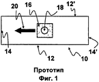
- Фигура 1 - схематичный вид в плане изложницы для непрерывной разливки, включающей разливочный стакан в соответствии с прототипом,- Figure 1 is a schematic plan view of a mold for continuous casting, including a casting cup in accordance with the prototype,
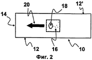
- Фигура 2 - схематичный вид в плане изложницы для непрерывной разливки, включающей разливочный стакан в соответствии с одним примером осуществления изобретения,- Figure 2 is a schematic plan view of a mold for continuous casting, including a casting cup in accordance with one embodiment of the invention,
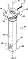
- Фигура 3 - изометрическая перспектива разливочного стакана в соответствии с одним примером осуществления изобретения,- Figure 3 is an isometric perspective of a nozzle in accordance with one embodiment of the invention,
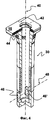
- Фигура 4 - изометрическая перспектива с поперечным сечением разливочного стакана в соответствии с одним примером осуществления изобретения.- Figure 4 is an isometric perspective with a cross section of a nozzle in accordance with one embodiment of the invention.
На фигурах 1 и 2 схематично изображена изложница 20, примерно прямоугольной формы, имеющая две длинные стороны 12, 12' и две короткие стороны 14, 14'. Представлен вид сверху разливочного стакана в центре изложницы, только верхняя поверхность 16 которого снабжена разливочным дроссельным отверстием 18. На этих фигурах детали устройства ввода и замены не видны. В каждой изложнице также указано направление 20 скольжения разливочного стакана в устройстве ввода и замены стакана. Следует отметить, что разгрузочные отверстия разливочного стакана, показанного на фигурах 1 и 2, располагаются на одной прямой в направлении, параллельном направлению скольжения 20. Несмотря на то что разливочное дроссельное отверстие 18 стакана, известного из прототипа (фигура 1), круглого сечения и центрировано относительно верхней поверхности 16, разливочное дроссельное отверстие 18 разливочного стакана в соответствии с изобретением (фигура 2) имеет продолговатую форму. Дроссельное отверстие вытянуто в направлении, перпендикулярном к направлению 20 скольжения стакана и, следовательно, перпендикулярно к направлению выпускных отверстий (не показано). Продолговатое отверстие 18 смещено от центра в направлении 20 скольжения и расположено спереди плиты в этом направлении.In figures 1 and 2 schematically shows a
На фигурах 3 и 4 показаны детали разливочного стакана 30 в соответствии с конкретным примером осуществления изобретения. На двух фигурах показан один и тот же разливочный стакан 30, включающий на верхнем конце 32 плиту 34 примерно прямоугольной формы, имеющую верхнюю поверхность 16 и нижнюю поверхность. Стакан 30 также включает трубу 38, ось 40 которой в основном ортогональна к верхней поверхности 16 плиты 34. Труба 38 проходит от нижней поверхности плиты 34 до нижнего конца 36 стакана. Стакан включает разливочный канал, состоящий из впускного дроссельного отверстия 18, проходящего через поверхность 16 плиты 34, проходное отверстие в плите 34, проходное отверстие 50 в трубе 38; нижний конец 36 трубы закрыт и выпуск из разливочного канала происходит рядом с нижним концом 36 через выпускные отверстия 46, 46', выполненные в боковых стенках трубы 38. Дроссельное отверстие плиты 34, проходные отверстия в плите и трубе и выпускные отверстия находятся в жидкостном соединении. Выпускные отверстия 46, 46' расположены симметрично с обеих сторон оси 40 трубы 38. Центры выпускных отверстий 46, 46' с обеих сторон оси 40 определяют ось выпускных отверстий 48, в основном ортогонально к оси, определенной разливочным каналом. Ось выпускных отверстий в основном параллельна двум сторонам плиты 34. Дроссельное отверстие 18 продолговатое и имеет большую ось 42 и малую ось 44. Малая ось 44 дроссельного отверстия 18 параллельна оси 48 выпускных отверстий.Figures 3 and 4 show details of a
Claims (5)
Applications Claiming Priority (3)
| Application Number | Priority Date | Filing Date | Title |
|---|---|---|---|
| EP09173696A EP2319640A1 (en) | 2009-10-21 | 2009-10-21 | Casting nozzle and assembly of such a nozzle with an inner nozzle |
| EP09173696.7 | 2009-10-21 | ||
| PCT/EP2010/006410 WO2011047850A1 (en) | 2009-10-21 | 2010-10-20 | Pouring nozzle and assembly of such a pouring nozzle with an inner nozzle |
Publications (2)
| Publication Number | Publication Date |
|---|---|
| RU2012112621A RU2012112621A (en) | 2013-11-27 |
| RU2551742C2 true RU2551742C2 (en) | 2015-05-27 |
Family
ID=42470640
Family Applications (1)
| Application Number | Title | Priority Date | Filing Date |
|---|---|---|---|
| RU2012112621/02A RU2551742C2 (en) | 2009-10-21 | 2010-10-20 | Pouring nozzle and mounting assembly including it |
Country Status (19)
| Country | Link |
|---|---|
| US (1) | US8905274B2 (en) |
| EP (2) | EP2319640A1 (en) |
| JP (1) | JP5519797B2 (en) |
| KR (1) | KR101689919B1 (en) |
| CN (1) | CN102665967B (en) |
| AR (1) | AR080344A1 (en) |
| AU (1) | AU2010310090B2 (en) |
| BR (1) | BR112012009152A2 (en) |
| CA (1) | CA2777076A1 (en) |
| CL (1) | CL2012001016A1 (en) |
| IN (1) | IN2012DN02791A (en) |
| MX (1) | MX336555B (en) |
| MY (1) | MY155670A (en) |
| NZ (1) | NZ598948A (en) |
| RU (1) | RU2551742C2 (en) |
| TW (1) | TWI522189B (en) |
| UA (1) | UA106396C2 (en) |
| WO (1) | WO2011047850A1 (en) |
| ZA (1) | ZA201202297B (en) |
Cited By (1)
| Publication number | Priority date | Publication date | Assignee | Title |
|---|---|---|---|---|
| RU2760749C1 (en) * | 2017-11-10 | 2021-11-30 | Везувиус Груп, С.А. | Self-locking system of the internal pouring nozzle |
Families Citing this family (9)
| Publication number | Priority date | Publication date | Assignee | Title |
|---|---|---|---|---|
| ES2609983T3 (en) * | 2013-06-20 | 2017-04-25 | Refractory Intellectual Property Gmbh & Co. Kg | Submerged refractory inlet nozzle |
| CN105689698A (en) * | 2016-03-09 | 2016-06-22 | 日照钢铁控股集团有限公司 | Braking-type submerged nozzle for beam blank continuous casting |
| CN110023008A (en) | 2016-11-23 | 2019-07-16 | Ak钢铁产权公司 | Continuously casting nozzle guide device |
| KR102083536B1 (en) * | 2017-11-14 | 2020-03-02 | 주식회사 포스코 | Submerged nozzle and Method for treatment of molten steel |
| KR102008703B1 (en) * | 2017-12-18 | 2019-08-08 | 주식회사 포스코 | Continuous casting nozzle |
| CN109465437A (en) * | 2018-12-15 | 2019-03-15 | 江苏盛耐新材料有限公司 | A kind of steel ladle integral type nozzle brick being conveniently replaceable |
| US11359374B2 (en) * | 2020-02-21 | 2022-06-14 | Michael Callahan | Leg-carriage type trusses |
| CN113319259B (en) * | 2021-06-07 | 2022-09-20 | 东北电力大学 | Bonding breakout logic judgment method based on space-time sequence characteristics |
| CN114632927A (en) * | 2022-03-17 | 2022-06-17 | 南京高速齿轮制造有限公司 | Multi-section continuous casting equipment and multi-section same tundish continuous casting process |
Citations (4)
| Publication number | Priority date | Publication date | Assignee | Title |
|---|---|---|---|---|
| FR2635030A1 (en) * | 1988-07-18 | 1990-02-09 | Vesuvius France Sa | Integral slide valve and casting tube component |
| WO1996034838A1 (en) * | 1995-05-02 | 1996-11-07 | Baker Refractories | Apparatus for discharging molten metal in a casting device and method of use |
| WO2003041894A2 (en) * | 2001-11-13 | 2003-05-22 | Vesuvius Crucible Company | Multi-hole, multi-edge control plate for linear sliding gate |
| RU2308353C2 (en) * | 2005-01-28 | 2007-10-20 | ООО "Модуль-Инжиниринг" | Submersible dead-bottom nozzle |
Family Cites Families (10)
| Publication number | Priority date | Publication date | Assignee | Title |
|---|---|---|---|---|
| US377943A (en) * | 1888-02-14 | Match-machine | ||
| CH500794A (en) * | 1969-06-09 | 1970-12-31 | Metacon Ag | Slide gate on a pouring vessel intended to hold liquid metal |
| CH663365A5 (en) * | 1984-05-11 | 1987-12-15 | Stopinc Ag | SEALING PLATE COUPLING FOR A SLIDING CLOSURE ON THE SPOUT OF MELT, IN PARTICULAR METAL MELT, CONTAINERS CONTAINING. |
| CH663368A5 (en) * | 1984-06-20 | 1987-12-15 | Stopinc Ag | SLIDING SEAL FOR THE SPOUT, IN PARTICULAR HORIZONTAL SPOUT, MILLED FROM METAL MELT. |
| BE901564A (en) | 1985-01-24 | 1985-07-24 | Szadkowski Stanislav | DEVICE FOR FEEDING AND EXCHANGING A CASTING TUBE. |
| US5494201A (en) | 1995-01-24 | 1996-02-27 | International Industrial Engineering S.A. | Device for inserting a retractable blank shutting off plate in a device for the conveyance and exchange of a pouring tube |
| US5866022A (en) * | 1997-03-24 | 1999-02-02 | North American Refractories Company | Refractory pour tube with cast plate |
| WO2003080274A1 (en) * | 2002-03-25 | 2003-10-02 | Stopinc Aktiengesellschaft | Method for operating a sliding gate, and sliding gate |
| ZA200507285B (en) * | 2003-03-17 | 2006-12-27 | Vesuvius Crucible Co | Submerged entry nozzle with dynamic stabilization |
| CN2737488Y (en) * | 2004-10-25 | 2005-11-02 | 山东中齐耐火材料有限公司 | Submersed pouring nozzle for continuous casting wide and thick plate slab |
-
2009
- 2009-10-21 EP EP09173696A patent/EP2319640A1/en not_active Withdrawn
-
2010
- 2010-10-18 TW TW099135416A patent/TWI522189B/en not_active IP Right Cessation
- 2010-10-19 AR ARP100103810A patent/AR080344A1/en unknown
- 2010-10-20 MY MYPI2012001428A patent/MY155670A/en unknown
- 2010-10-20 EP EP10771019A patent/EP2490845A1/en not_active Withdrawn
- 2010-10-20 WO PCT/EP2010/006410 patent/WO2011047850A1/en active Application Filing
- 2010-10-20 AU AU2010310090A patent/AU2010310090B2/en not_active Ceased
- 2010-10-20 MX MX2012004669A patent/MX336555B/en unknown
- 2010-10-20 RU RU2012112621/02A patent/RU2551742C2/en not_active IP Right Cessation
- 2010-10-20 CN CN201080058966.0A patent/CN102665967B/en not_active Expired - Fee Related
- 2010-10-20 KR KR1020127012959A patent/KR101689919B1/en active IP Right Grant
- 2010-10-20 CA CA2777076A patent/CA2777076A1/en not_active Abandoned
- 2010-10-20 JP JP2012534577A patent/JP5519797B2/en not_active Expired - Fee Related
- 2010-10-20 NZ NZ598948A patent/NZ598948A/en not_active IP Right Cessation
- 2010-10-20 US US13/503,222 patent/US8905274B2/en not_active Expired - Fee Related
- 2010-10-20 UA UAA201206161A patent/UA106396C2/en unknown
- 2010-10-20 BR BR112012009152A patent/BR112012009152A2/en active Search and Examination
-
2012
- 2012-03-29 ZA ZA2012/02297A patent/ZA201202297B/en unknown
- 2012-04-02 IN IN2791DEN2012 patent/IN2012DN02791A/en unknown
- 2012-04-20 CL CL2012001016A patent/CL2012001016A1/en unknown
Patent Citations (4)
| Publication number | Priority date | Publication date | Assignee | Title |
|---|---|---|---|---|
| FR2635030A1 (en) * | 1988-07-18 | 1990-02-09 | Vesuvius France Sa | Integral slide valve and casting tube component |
| WO1996034838A1 (en) * | 1995-05-02 | 1996-11-07 | Baker Refractories | Apparatus for discharging molten metal in a casting device and method of use |
| WO2003041894A2 (en) * | 2001-11-13 | 2003-05-22 | Vesuvius Crucible Company | Multi-hole, multi-edge control plate for linear sliding gate |
| RU2308353C2 (en) * | 2005-01-28 | 2007-10-20 | ООО "Модуль-Инжиниринг" | Submersible dead-bottom nozzle |
Cited By (1)
| Publication number | Priority date | Publication date | Assignee | Title |
|---|---|---|---|---|
| RU2760749C1 (en) * | 2017-11-10 | 2021-11-30 | Везувиус Груп, С.А. | Self-locking system of the internal pouring nozzle |
Also Published As
| Publication number | Publication date |
|---|---|
| ZA201202297B (en) | 2013-06-26 |
| MY155670A (en) | 2015-11-13 |
| AU2010310090A1 (en) | 2012-04-12 |
| EP2319640A1 (en) | 2011-05-11 |
| KR101689919B1 (en) | 2016-12-26 |
| AU2010310090B2 (en) | 2014-05-08 |
| UA106396C2 (en) | 2014-08-26 |
| CN102665967A (en) | 2012-09-12 |
| EP2490845A1 (en) | 2012-08-29 |
| TWI522189B (en) | 2016-02-21 |
| CL2012001016A1 (en) | 2012-11-30 |
| BR112012009152A2 (en) | 2016-08-30 |
| CA2777076A1 (en) | 2011-04-28 |
| KR20120098727A (en) | 2012-09-05 |
| TW201124214A (en) | 2011-07-16 |
| JP5519797B2 (en) | 2014-06-11 |
| AR080344A1 (en) | 2012-04-04 |
| US8905274B2 (en) | 2014-12-09 |
| CN102665967B (en) | 2015-05-20 |
| NZ598948A (en) | 2013-01-25 |
| MX336555B (en) | 2016-01-21 |
| JP2013508160A (en) | 2013-03-07 |
| MX2012004669A (en) | 2012-06-14 |
| RU2012112621A (en) | 2013-11-27 |
| US20120211531A1 (en) | 2012-08-23 |
| IN2012DN02791A (en) | 2015-07-24 |
| WO2011047850A1 (en) | 2011-04-28 |
Similar Documents
| Publication | Publication Date | Title |
|---|---|---|
| RU2551742C2 (en) | Pouring nozzle and mounting assembly including it | |
| CN100453209C (en) | Intermediate bag with molten metal return-guide and split apparatus | |
| JPH0675753B2 (en) | Method and apparatus for controlling a conducting liquid flow | |
| ITMI961243A1 (en) | DIVER FOR CONTINUOUS CASTING OF THIN SLABS | |
| RU2570259C2 (en) | Teeming barrel for metal melt direction | |
| JP3050101B2 (en) | Continuous casting pouring equipment | |
| KR101277171B1 (en) | Shroud nozzle for continuous casting | |
| KR20080064428A (en) | Stopper for continuous casting | |
| KR20190088506A (en) | Continuous casting nozzle deflector | |
| RU185699U1 (en) | BUCKET METAL RECEIVER | |
| KR101003940B1 (en) | Tundish and method for production of a metal strip of high purity | |
| CN216540828U (en) | Tundish nozzle steel retaining groove, tundish nozzle and tundish | |
| KR100779714B1 (en) | Apparatus for closing of submerged entry nozzle | |
| RU2756838C2 (en) | Cup of an asymmetric shape for casting slabs and metallurgical plant for casting metal that includes it | |
| CN210966899U (en) | Flow divider device with baffle for multi-flow tundish | |
| JP2008178884A (en) | Method for continuously casting steel | |
| KR100530102B1 (en) | Molten steel flow distributing pad for the continuous casting tundish | |
| EP3725430A1 (en) | Molten material processing device | |
| GB1592554A (en) | Pouring of molten metal from a teeming vessel | |
| KR101749077B1 (en) | Tundish and Method for casting using the same | |
| SK7238Y1 (en) | Process of continous casting of steel | |
| JP5009033B2 (en) | Steel continuous casting method and continuous casting apparatus | |
| TW201440924A (en) | Ladle bottom and ladle | |
| JP2015093290A (en) | Lower injected steel ingot casting apparatus | |
| KR20140060934A (en) | Apparatus for controlling melten metal flow and the method thereof |
Legal Events
| Date | Code | Title | Description |
|---|---|---|---|
| MM4A | The patent is invalid due to non-payment of fees |
Effective date: 20171021 |