RU2550835C2 - Fluid sprayer - Google Patents

Fluid sprayer Download PDF

Info

Publication number
RU2550835C2
RU2550835C2 RU2013119199/05A RU2013119199A RU2550835C2 RU 2550835 C2 RU2550835 C2 RU 2550835C2 RU 2013119199/05 A RU2013119199/05 A RU 2013119199/05A RU 2013119199 A RU2013119199 A RU 2013119199A RU 2550835 C2 RU2550835 C2 RU 2550835C2
Authority
RU
Russia
Prior art keywords
nozzle
insert
swirl insert
swirl
housing
Prior art date
Application number
RU2013119199/05A
Other languages
Russian (ru)
Other versions
RU2013119199A (en
Inventor
Олег Савельевич Кочетов
Мария Олеговна Стареева
Мария Михайловна Стареева
Original Assignee
Олег Савельевич Кочетов
Мария Олеговна Стареева
Мария Михайловна Стареева
Priority date (The priority date is an assumption and is not a legal conclusion. Google has not performed a legal analysis and makes no representation as to the accuracy of the date listed.)
Filing date
Publication date
Application filed by Олег Савельевич Кочетов, Мария Олеговна Стареева, Мария Михайловна Стареева filed Critical Олег Савельевич Кочетов
Priority to RU2013119199/05A priority Critical patent/RU2550835C2/en
Publication of RU2013119199A publication Critical patent/RU2013119199A/en
Application granted granted Critical
Publication of RU2550835C2 publication Critical patent/RU2550835C2/en

Links

Images

Abstract

FIELD: process engineering.
SUBSTANCE: invention relates to sprayers. Spraying nozzle has swirling insert fitted in the nozzle case via resilient spacers and squeezed by union by threaded joint case-union. External helical cut channels and screw cut on inner surface of axial bore of said swirling insert are arranged at variable pitch. Swirling insert is composed of the stack of coaxial helical springs or cylindrical helical variable-pitch springs. Swirling insert is composed of the stack of coaxial helical springs. Direction of spring screw lines alternate the next but one.
EFFECT: higher quality of spraying and efficiency.
1 dwg

Description

Изобретение относится к технике распыления жидкостей.The invention relates to techniques for spraying liquids.

Наиболее близким техническим решением к заявленному объекту является форсунка по патенту РФ №2465065, B05B 1/34, которая содержит корпус с подводящим жидкость каналом, камерой завихрения и выходным соплом, установленную в корпусе вставку в виде усеченного конуса, меньшим основанием обращенным к соплу, причем на наружной поверхности вставки выполнена многозаходная винтовая нарезка.The closest technical solution to the claimed object is the nozzle according to the patent of Russian Federation No. 2465065, B05B 1/34, which contains a housing with a fluid supply channel, a swirl chamber and an output nozzle, an insert in the form of a truncated cone with a smaller base facing the nozzle, and on the outer surface of the insert is made multi-thread screw cutting.

Недостатком известной форсунки для распыления жидкости является то, что при высокой скорости вращения жидкости в сопле форсунки возникает воздушный вихрь, ухудшающий вход жидкости в сопло и снижающий производительность и качество распыления жидкости форсункой.A disadvantage of the known nozzle for spraying liquid is that at a high speed of rotation of the liquid, an air vortex arises in the nozzle of the nozzle, which worsens the fluid entry into the nozzle and reduces the productivity and quality of the liquid sprayed by the nozzle.

Технический результат - повышение качества распыления жидкости, производительности форсунки, уменьшение гидравлических потерь.EFFECT: improved quality of liquid atomization, nozzle productivity, reduced hydraulic losses.

Это достигается тем, что в форсунке для распыления жидкости, содержащей корпус, штуцер и соосно расположенную с ними вставку-завихритель, в штуцере выполнен расширяющийся канал для подвода жидкости в цилиндрическое отверстие, которое выполнено осесимметрично корпусу и плавно переходит в соосное с ним фигурное отверстие, выполненное в форме диффузора, а в цилиндрическом отверстии корпуса, осесимметрично ему, установлена цилиндрическая вставка-завихритель, имеющая внешние периферийные винтообразные нарезные каналы, причем по оси вставки-завихрителя выполнено центральное осевое отверстие с винтовой нарезкой на внутренней поверхности, обратной направлению нарезки каналов, при этом вставка-завихритель устанавливается в корпусе через упругие прокладки и поджимается штуцером посредством резьбового соединения корпус-штуцер.This is achieved by the fact that in the nozzle for spraying a fluid containing a housing, a fitting and a swirl insert coaxially located with them, an expanding channel is made in the fitting for supplying fluid to a cylindrical hole, which is made axisymmetrically to the body and smoothly passes into a figured hole coaxial with it, made in the form of a diffuser, and in the cylindrical hole of the housing, axisymmetric to it, a cylindrical swirl insert is installed, having external peripheral helical threaded channels, and along the axis of the insert The i-swirler has a central axial hole with screw thread on the inner surface, the opposite direction of the channel cutting, while the swirl insert is installed in the housing through elastic gaskets and is pressed by the fitting by means of a threaded housing-fitting connection.

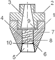
На чертеже представлен продольный разрез форсунки.The drawing shows a longitudinal section of a nozzle.

Форсунка для распыления жидкости состоит из корпуса 1 и соосно расположенного с ним в верхней части, штуцера 2, в котором выполнен расширяющийся канал 3 для подвода жидкости в цилиндрическое отверстие 4, выполненное осесимметрично корпусу 1. Цилиндрическое отверстие 4 плавно переходит в соосное с ним отверстие 5, выполненное в форме диффузора. В отверстии 4 корпуса осесимметрично ему установлена цилиндрическая вставка-завихритель 6, имеющая внешние периферийные винтообразные нарезные каналы 7. По оси вставки-завихрителя 6 выполнено центральное осевое отверстие 8 с винтовой нарезкой на внутренней поверхности, обратной направлению нарезки каналов 7. Внешние винтообразные нарезные каналы 7 и винтовая нарезка на внутренней поверхности осевого отверстия 8 могут быть выполнены с переменным шагом. Вставка-завихритель 6 устанавливается в корпусе 1 через упругие прокладки 9 и 10 и поджимается штуцером 2 посредством резьбового соединения корпус-штуцер, при этом вставка-завихритель выполнена из износостойкого материала.The nozzle for spraying liquid consists of a housing 1 and a nozzle 2 coaxially located with it in the upper part, in which an expanding channel 3 is made for supplying liquid to a cylindrical hole 4, made axisymmetrically to the housing 1. The cylindrical hole 4 smoothly passes into the coaxial hole 5 made in the form of a diffuser. A cylindrical swirl insert 6 is mounted axisymmetrically in the opening 4 of the casing, having external peripheral screw-shaped threaded channels 7. A central axial hole 8 is made along the axis of the swirl-insert 6 with a screw thread on the inner surface, the reverse direction of channel cutting 7. External screw-shaped threaded channels 7 and screw cutting on the inner surface of the axial hole 8 can be performed with a variable pitch. The swirl insert 6 is installed in the housing 1 through the elastic gaskets 9 and 10 and is pressed by the fitting 2 by means of a threaded housing-fitting connection, while the swirl insert is made of wear-resistant material.

Вставка-завихритель может быть выполнена в виде пакета соосных цилиндрических винтовых пружин (на чертеже не показано).The swirl insert can be made in the form of a package of coaxial cylindrical coil springs (not shown in the drawing).

Вставка-завихритель может быть выполнена в виде пакета соосных цилиндрических винтовых пружин с переменным шагом (на чертеже не показано).The swirl insert can be made in the form of a package of coaxial cylindrical coil springs with a variable pitch (not shown in the drawing).

Вставка-завихритель может быть выполнена в виде пакета соосных цилиндрических винтовых пружин, причем направление винтовых линий пружин в пакете чередуется через одну (на чертеже не показано).The swirl insert can be made in the form of a packet of coaxial cylindrical coil springs, and the direction of the coil lines of the springs in the packet alternates through one (not shown in the drawing).

Форсунка для распыления жидкости работает следующим образом.The nozzle for spraying liquid works as follows.

Жидкость в корпус 1 поступает через канал 3 подвода жидкости в штуцере 2, а затем в центральное цилиндрическое отверстие 4. Жидкость начинает свою закрутку в периферийных каналах вставки-завихрителя 6 и одновременно во внутренних каналах центрального осевого отверстия 8 с обратным направлением. Такой поток жидкости на выходе из фигурного отверстия 5 в форме диффузора хорошо раскрывается за счет центробежных сил, возникающих от вращения жидкости, и мелкодисперсно распределяется внутри конусообразного факела за счет турбулентного течения по оси сопла.The fluid enters the housing 1 through the fluid supply channel 3 in the nozzle 2, and then into the central cylindrical hole 4. The fluid begins to swirl in the peripheral channels of the swirl insert 6 and simultaneously in the internal channels of the central axial hole 8 with the opposite direction. Such a fluid flow at the outlet of the figured hole 5 in the form of a diffuser is well disclosed due to centrifugal forces arising from the rotation of the liquid, and is finely dispersed inside the conical torch due to the turbulent flow along the nozzle axis.

Claims (1)

Форсунка для распыления жидкости, содержащая корпус, штуцер и соосно расположенную с ними вставку-завихритель, в штуцере выполнен расширяющийся канал для подвода жидкости в цилиндрическое отверстие, которое выполнено осесимметрично корпусу и плавно переходит в соосное с ним фигурное отверстие, выполненное в форме диффузора, а в цилиндрическом отверстии корпуса осесимметрично ему установлена цилиндрическая вставка-завихритель, имеющая внешние периферийные винтообразные нарезные каналы, причем по оси вставки-завихрителя выполнено центральное осевое отверстие с винтовой нарезкой на внутренней поверхности, обратной направлению нарезки каналов, отличающаяся тем, что вставка-завихритель устанавливается в корпусе через упругие прокладки и поджимается штуцером посредством резьбового соединения корпус-штуцер, внешние винтообразные нарезные каналы и винтовая нарезка на внутренней поверхности осевого отверстия вставки-завихрителя выполнены с переменным шагом, а вставка-завихритель выполнена из износостойкого материала, или вставка-завихритель выполнена в виде пакета соосных цилиндрических винтовых пружин или цилиндрических винтовых пружин с переменным шагом, или направление винтовых линий пружин в пакете чередуется через одну. A nozzle for spraying a fluid, comprising a housing, a fitting and a swirl insert coaxially located with them, in the fitting there is an expanding channel for supplying fluid to a cylindrical hole, which is made axisymmetrically to the body and smoothly passes into a coaxial shaped hole made in the form of a diffuser, and in the cylindrical hole of the housing, a cylindrical swirl insert is mounted axisymmetrically to it, having external peripheral helical threaded channels, moreover, along the axis of the swirl insert a swivel axial hole with a screw thread on the inner surface, the opposite direction of the channel cutting, characterized in that the swirl insert is installed in the housing through elastic gaskets and is pressed by a fitting by means of a threaded connection to the nozzle, external screw-shaped threaded channels and screw thread on the inner surface of the axial hole swirl inserts are made with variable pitch, and swirl insert is made of wear-resistant material, or swirl insert is made in the form of a package coaxial coil springs or coil springs with variable pitch, or the direction of the coil lines of the springs in the package alternates through one.
RU2013119199/05A 2013-04-25 2013-04-25 Fluid sprayer RU2550835C2 (en)

Priority Applications (1)

Application Number Priority Date Filing Date Title
RU2013119199/05A RU2550835C2 (en) 2013-04-25 2013-04-25 Fluid sprayer

Applications Claiming Priority (1)

Application Number Priority Date Filing Date Title
RU2013119199/05A RU2550835C2 (en) 2013-04-25 2013-04-25 Fluid sprayer

Publications (2)

Publication Number Publication Date
RU2013119199A RU2013119199A (en) 2014-10-27
RU2550835C2 true RU2550835C2 (en) 2015-05-20

Family

ID=53294416

Family Applications (1)

Application Number Title Priority Date Filing Date
RU2013119199/05A RU2550835C2 (en) 2013-04-25 2013-04-25 Fluid sprayer

Country Status (1)

Country Link
RU (1) RU2550835C2 (en)

Cited By (8)

* Cited by examiner, † Cited by third party
Publication number Priority date Publication date Assignee Title
RU2622794C1 (en) * 2016-03-14 2017-06-20 Олег Савельевич Кочетов Nozzle for liquid spray
RU2642579C1 (en) * 2017-02-27 2018-01-25 Олег Савельевич Кочетов Nozzle for spraying liquid
RU2646923C1 (en) * 2017-06-29 2018-03-12 Олег Савельевич Кочетов Cyclone combined
RU2650930C1 (en) * 2017-06-29 2018-04-18 Олег Савельевич Кочетов Nozzle scrubber
RU2667848C1 (en) * 2018-01-22 2018-09-24 Заур Нурбиевич Османов Ventilation system with heat recovery unit
RU2669173C1 (en) * 2018-01-22 2018-10-08 Олег Иванович Седляров Heat recovery unit with boiling bed of inert head
RU2669893C1 (en) * 2018-01-22 2018-10-16 Никита Валерьевич Дерюгин Spray dryer
RU2669820C1 (en) * 2018-01-22 2018-10-16 Олег Иванович Седляров Scrubber

Families Citing this family (2)

* Cited by examiner, † Cited by third party
Publication number Priority date Publication date Assignee Title
RU2585808C1 (en) * 2015-05-07 2016-06-10 Татьяна Дмитриевна Ходакова Nozzle for spraying liquid
RU2648070C2 (en) * 2015-05-20 2018-03-22 Анна Михайловна Стареева Nozzle for spraying liquid

Citations (8)

* Cited by examiner, † Cited by third party
Publication number Priority date Publication date Assignee Title
DE715339C (en) * 1939-12-08 1941-12-19 Fried Krupp Germaniawerft Ag Pressure atomizer for liquid fuels
GB994109A (en) * 1962-05-28 1965-06-02 Chemical Construction Corp Sulphur spray atomizer
GB1067717A (en) * 1964-08-06 1967-05-03 Urquhart S 1926 Ltd Improvements relating to atomisers
RU2296013C2 (en) * 2005-04-13 2007-03-27 Валерий Николаевич Тесленко Method and injector for spraying liquids
RU2339875C1 (en) * 2007-03-13 2008-11-27 Олег Савельевич Кочетов Centrifugal nozzle
RU2388518C1 (en) * 2009-01-15 2010-05-10 Олег Савельевич Кочетов Device to clean and recover flue gases
RU2422725C1 (en) * 2010-05-14 2011-06-27 Олег Савельевич Кочетов Centrifugal sprayer with paired swirled flows of cochstar type
RU2464068C1 (en) * 2011-08-30 2012-10-20 Олег Савельевич Кочетов Heat recovery hydraulic ash catcher

Patent Citations (8)

* Cited by examiner, † Cited by third party
Publication number Priority date Publication date Assignee Title
DE715339C (en) * 1939-12-08 1941-12-19 Fried Krupp Germaniawerft Ag Pressure atomizer for liquid fuels
GB994109A (en) * 1962-05-28 1965-06-02 Chemical Construction Corp Sulphur spray atomizer
GB1067717A (en) * 1964-08-06 1967-05-03 Urquhart S 1926 Ltd Improvements relating to atomisers
RU2296013C2 (en) * 2005-04-13 2007-03-27 Валерий Николаевич Тесленко Method and injector for spraying liquids
RU2339875C1 (en) * 2007-03-13 2008-11-27 Олег Савельевич Кочетов Centrifugal nozzle
RU2388518C1 (en) * 2009-01-15 2010-05-10 Олег Савельевич Кочетов Device to clean and recover flue gases
RU2422725C1 (en) * 2010-05-14 2011-06-27 Олег Савельевич Кочетов Centrifugal sprayer with paired swirled flows of cochstar type
RU2464068C1 (en) * 2011-08-30 2012-10-20 Олег Савельевич Кочетов Heat recovery hydraulic ash catcher

Non-Patent Citations (1)

* Cited by examiner, † Cited by third party
Title
ПАЖИ Д.Г. И ГАЛУСТОВ В.С. ОСНОВЫ ТЕХНИКИ РАСПЫЛИВАНИЯ ЖИДКОСТИ. МОСКВА, «ХИМИЯ», 1984? c.72, рис.4.1.б *

Cited By (8)

* Cited by examiner, † Cited by third party
Publication number Priority date Publication date Assignee Title
RU2622794C1 (en) * 2016-03-14 2017-06-20 Олег Савельевич Кочетов Nozzle for liquid spray
RU2642579C1 (en) * 2017-02-27 2018-01-25 Олег Савельевич Кочетов Nozzle for spraying liquid
RU2646923C1 (en) * 2017-06-29 2018-03-12 Олег Савельевич Кочетов Cyclone combined
RU2650930C1 (en) * 2017-06-29 2018-04-18 Олег Савельевич Кочетов Nozzle scrubber
RU2667848C1 (en) * 2018-01-22 2018-09-24 Заур Нурбиевич Османов Ventilation system with heat recovery unit
RU2669173C1 (en) * 2018-01-22 2018-10-08 Олег Иванович Седляров Heat recovery unit with boiling bed of inert head
RU2669893C1 (en) * 2018-01-22 2018-10-16 Никита Валерьевич Дерюгин Spray dryer
RU2669820C1 (en) * 2018-01-22 2018-10-16 Олег Иванович Седляров Scrubber

Also Published As

Publication number Publication date
RU2013119199A (en) 2014-10-27

Similar Documents

Publication Publication Date Title
RU2550835C2 (en) Fluid sprayer
RU2465065C1 (en) Fluid atomiser
RU2413581C1 (en) Fluid sprayer
RU2501611C1 (en) Kss-type nozzle
RU2527805C1 (en) Kochetov's swirl atomiser
RU2480295C1 (en) Kochetov's swirl atomiser
RU2570441C1 (en) Kochetov's swirl atomiser
RU2532864C1 (en) Kochetov's swirl atomiser
RU2585808C1 (en) Nozzle for spraying liquid
RU2504441C1 (en) Sprayer
RU2455562C1 (en) Centrifugal nozzle
RU2570438C1 (en) Kss-type nozzle
RU2488038C1 (en) Swirler with active sprayer
RU2622794C1 (en) Nozzle for liquid spray
RU2479355C1 (en) Centrifugal sprayer
RU2539183C1 (en) Kochetov's centrifugal atomiser with active spray gun
RU2642579C1 (en) Nozzle for spraying liquid
RU2624112C1 (en) Atomizer with active spreader
RU2011104808A (en) VORTEX TYPE FOAM GENERATOR
RU2638357C1 (en) Injector with screw conical swirler
RU2545260C1 (en) Centrifugal wide-flare sprayer
RU2551455C1 (en) Kochetov's swirl injector
RU2015118850A (en) LIQUID SPRAY NOZZLE
RU2015118864A (en) LIQUID SPRAY NOZZLE
RU2653988C2 (en) Stareeva atomizer

Legal Events

Date Code Title Description
FZ9A Application not withdrawn (correction of the notice of withdrawal)

Effective date: 20140903