RU2550107C1 - Device to control air pressure in tyres - Google Patents
Device to control air pressure in tyres Download PDFInfo
- Publication number
- RU2550107C1 RU2550107C1 RU2013152161/11A RU2013152161A RU2550107C1 RU 2550107 C1 RU2550107 C1 RU 2550107C1 RU 2013152161/11 A RU2013152161/11 A RU 2013152161/11A RU 2013152161 A RU2013152161 A RU 2013152161A RU 2550107 C1 RU2550107 C1 RU 2550107C1
- Authority
- RU
- Russia
- Prior art keywords
- wheel
- angular position
- tire
- sensor
- tpms
- Prior art date
Links
Images
Classifications
-
- B—PERFORMING OPERATIONS; TRANSPORTING
- B60—VEHICLES IN GENERAL
- B60C—VEHICLE TYRES; TYRE INFLATION; TYRE CHANGING; CONNECTING VALVES TO INFLATABLE ELASTIC BODIES IN GENERAL; DEVICES OR ARRANGEMENTS RELATED TO TYRES
- B60C23/00—Devices for measuring, signalling, controlling, or distributing tyre pressure or temperature, specially adapted for mounting on vehicles; Arrangement of tyre inflating devices on vehicles, e.g. of pumps or of tanks; Tyre cooling arrangements
- B60C23/02—Signalling devices actuated by tyre pressure
- B60C23/04—Signalling devices actuated by tyre pressure mounted on the wheel or tyre
- B60C23/0408—Signalling devices actuated by tyre pressure mounted on the wheel or tyre transmitting the signals by non-mechanical means from the wheel or tyre to a vehicle body mounted receiver
- B60C23/0415—Automatically identifying wheel mounted units, e.g. after replacement or exchange of wheels
-
- B—PERFORMING OPERATIONS; TRANSPORTING
- B60—VEHICLES IN GENERAL
- B60C—VEHICLE TYRES; TYRE INFLATION; TYRE CHANGING; CONNECTING VALVES TO INFLATABLE ELASTIC BODIES IN GENERAL; DEVICES OR ARRANGEMENTS RELATED TO TYRES
- B60C23/00—Devices for measuring, signalling, controlling, or distributing tyre pressure or temperature, specially adapted for mounting on vehicles; Arrangement of tyre inflating devices on vehicles, e.g. of pumps or of tanks; Tyre cooling arrangements
- B60C23/02—Signalling devices actuated by tyre pressure
- B60C23/04—Signalling devices actuated by tyre pressure mounted on the wheel or tyre
- B60C23/0408—Signalling devices actuated by tyre pressure mounted on the wheel or tyre transmitting the signals by non-mechanical means from the wheel or tyre to a vehicle body mounted receiver
- B60C23/0415—Automatically identifying wheel mounted units, e.g. after replacement or exchange of wheels
- B60C23/0416—Automatically identifying wheel mounted units, e.g. after replacement or exchange of wheels allocating a corresponding wheel position on vehicle, e.g. front/left or rear/right
-
- B—PERFORMING OPERATIONS; TRANSPORTING
- B60—VEHICLES IN GENERAL
- B60C—VEHICLE TYRES; TYRE INFLATION; TYRE CHANGING; CONNECTING VALVES TO INFLATABLE ELASTIC BODIES IN GENERAL; DEVICES OR ARRANGEMENTS RELATED TO TYRES
- B60C23/00—Devices for measuring, signalling, controlling, or distributing tyre pressure or temperature, specially adapted for mounting on vehicles; Arrangement of tyre inflating devices on vehicles, e.g. of pumps or of tanks; Tyre cooling arrangements
- B60C23/02—Signalling devices actuated by tyre pressure
- B60C23/04—Signalling devices actuated by tyre pressure mounted on the wheel or tyre
- B60C23/0486—Signalling devices actuated by tyre pressure mounted on the wheel or tyre comprising additional sensors in the wheel or tyre mounted monitoring device, e.g. movement sensors, microphones or earth magnetic field sensors
- B60C23/0488—Movement sensor, e.g. for sensing angular speed, acceleration or centripetal force
-
- B—PERFORMING OPERATIONS; TRANSPORTING
- B60—VEHICLES IN GENERAL
- B60C—VEHICLE TYRES; TYRE INFLATION; TYRE CHANGING; CONNECTING VALVES TO INFLATABLE ELASTIC BODIES IN GENERAL; DEVICES OR ARRANGEMENTS RELATED TO TYRES
- B60C23/00—Devices for measuring, signalling, controlling, or distributing tyre pressure or temperature, specially adapted for mounting on vehicles; Arrangement of tyre inflating devices on vehicles, e.g. of pumps or of tanks; Tyre cooling arrangements
- B60C23/02—Signalling devices actuated by tyre pressure
- B60C23/04—Signalling devices actuated by tyre pressure mounted on the wheel or tyre
- B60C23/0486—Signalling devices actuated by tyre pressure mounted on the wheel or tyre comprising additional sensors in the wheel or tyre mounted monitoring device, e.g. movement sensors, microphones or earth magnetic field sensors
- B60C23/0489—Signalling devices actuated by tyre pressure mounted on the wheel or tyre comprising additional sensors in the wheel or tyre mounted monitoring device, e.g. movement sensors, microphones or earth magnetic field sensors for detecting the actual angular position of the monitoring device while the wheel is turning
-
- G—PHYSICS
- G01—MEASURING; TESTING
- G01L—MEASURING FORCE, STRESS, TORQUE, WORK, MECHANICAL POWER, MECHANICAL EFFICIENCY, OR FLUID PRESSURE
- G01L17/00—Devices or apparatus for measuring tyre pressure or the pressure in other inflated bodies
-
- G—PHYSICS
- G08—SIGNALLING
- G08C—TRANSMISSION SYSTEMS FOR MEASURED VALUES, CONTROL OR SIMILAR SIGNALS
- G08C17/00—Arrangements for transmitting signals characterised by the use of a wireless electrical link
- G08C17/02—Arrangements for transmitting signals characterised by the use of a wireless electrical link using a radio link
Landscapes
- Engineering & Computer Science (AREA)
- Mechanical Engineering (AREA)
- Physics & Mathematics (AREA)
- General Physics & Mathematics (AREA)
- Computer Networks & Wireless Communication (AREA)
- Measuring Fluid Pressure (AREA)
- Arrangements For Transmission Of Measured Signals (AREA)
- Regulating Braking Force (AREA)
Abstract
Description
Область техники, к которой относится изобретениеFIELD OF THE INVENTION
[0001] Настоящее изобретение относится к устройству контроля давления воздуха в шинах.[0001] The present invention relates to a device for monitoring tire pressure.
Уровень техникиState of the art
[0002] В устройстве контроля давления воздуха в шинах или пневматического давления, описанном в патентном документе 1, передатчик отправляет беспроводной сигнал в постоянном, заданном угловом положении. Когда беспроводные сигналы принимаются на стороне транспортного средства, угловые положения соответствующих колес обнаруживаются. Положение колеса, ассоциированное с передатчиком, соответствующим угловому положению, которое имеет наилучшую синхронизацию с периодом вывода беспроводного сигнала из угловых положений колес, определяется как положение колеса (положение колеса), с которым этот передатчик ассоциирован.[0002] In the tire pressure or pneumatic pressure monitoring device described in
Документы предшествующего уровня техникиBackground Documents
Патентный документPatent document
[0003] Патентный документ 1: Публикация японской патентной заявки № 2010-122023[0003] Patent Document 1: Publication of Japanese Patent Application No. 2010-122023
Сущность изобретенияSUMMARY OF THE INVENTION
Задача, которая должна быть решена изобретениемThe task to be solved by the invention
[0004] Согласно предшествующему уровню техники, описанному выше, угловое положение передатчика определяется из выходного значения датчика ускорения, и беспроводной сигнал выводится в момент времени, когда выходное значение датчика ускорения принимает заданное значение. В этот момент, когда управление торможением, такое как ABS-управление, выполняется, поскольку колесо под управлением подвергается продольному колебанию с очень коротким периодом, что нарушает обнаруженное значение датчика ускорения, передатчик, вероятно, будет определять угловое положение ошибочно и выводить беспроводной сигнал в угловом положении, отличном от заданного углового положения. Следовательно, по причине определения положения колеса передатчика на основе ошибочных данных по угловому положению, определение положения колеса вероятно должно быть отложено.[0004] According to the prior art described above, the angular position of the transmitter is determined from the output value of the acceleration sensor, and the wireless signal is output at the point in time when the output value of the acceleration sensor takes a predetermined value. At this point, when braking control, such as ABS control, is performed because the wheel under control is subjected to longitudinal oscillation with a very short period, which violates the detected value of the acceleration sensor, the transmitter will probably detect the angular position erroneously and output the wireless signal in the angular position other than a given angular position. Therefore, due to the determination of the transmitter wheel position based on erroneous data on the angular position, the determination of the wheel position should probably be delayed.
Задачей или целью настоящего изобретения является предоставление устройства контроля давления воздуха в шинах или пневматического давления, которое может пресекать задержку в определении положения колеса.An object or object of the present invention is to provide a device for monitoring tire pressure or pneumatic pressure, which can suppress a delay in determining a wheel position.
Механизм достижения целиGoal Achievement Mechanism
[0005] Для того, чтобы достигать цели, описанной выше, согласно настоящему изобретению, когда выполняется управление торможением, чтобы управлять давлением рабочего тормозного цилиндра колес, обнаружение каждого колеса будет запрещено.[0005] In order to achieve the goal described above, according to the present invention, when braking control is performed to control the pressure of the working brake cylinder of the wheels, detection of each wheel will be prohibited.
Эффект от изобретенияThe effect of the invention
[0006] Следовательно, согласно настоящему изобретению, когда присутствует вероятность, при которой беспроводной сигнал был передан от передатчика в угловом положении, отличном от заданного углового положения, угловое положение, ассоциированное с каждым колесом, соответствующим этому беспроводному сигналу, не будет обнаруживаться. Следовательно, предотвращается использование ошибочных данных углового положения для определения положения колеса, так что задержка в определении положения колеса может быть подавлена.[0006] Therefore, according to the present invention, when there is a probability that a wireless signal has been transmitted from the transmitter in an angular position other than the predetermined angular position, the angular position associated with each wheel corresponding to this wireless signal will not be detected. Therefore, the use of erroneous angular position data to determine the position of the wheel is prevented, so that a delay in determining the position of the wheel can be suppressed.
Краткое описание чертежейBrief Description of the Drawings
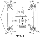
[0007] Фиг. 1 - это конфигурационная схема, иллюстрирующая конфигурацию устройства контроля давления воздуха в шинах в первом варианте осуществления;[0007] FIG. 1 is a configuration diagram illustrating a configuration of a tire pressure monitoring device in the first embodiment;
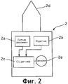
Фиг. 2 - это схема конфигурации TPMS-датчика 2;FIG. 2 is a configuration diagram of a
Фиг. 3 - это блок-схема управления, иллюстрирующая блок-схему управления TPMSCU 4 для выполнения управления определением положения колеса;FIG. 3 is a control block diagram illustrating a control block diagram of a
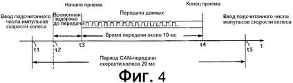
Фиг. 4 - это схема, иллюстрирующая способ вычисления углового положения каждого колеса 1;FIG. 4 is a diagram illustrating a method for calculating the angular position of each
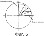
Фиг. 5 - это схема, иллюстрирующая способ вычисления значения дисперсионной характеристики;FIG. 5 is a diagram illustrating a method for calculating a dispersion characteristic value;
Фиг. 6 - это блок-схема последовательности операций, иллюстрирующая процесс управления определением положения колеса в первом варианте осуществления;FIG. 6 is a flowchart illustrating a wheel position determination control process in the first embodiment;
Фиг. 7 - это схема, иллюстрирующая соотношение между угловыми положениями (числом зубцов ротора) каждого из колес 1FL, 1FR, 1RL, 1RR, когда угловое положение TPMS-датчика 2FL левого переднего колеса 1FL принимает наивысшую точку, и числом приема TPMS-данных; иFIG. 7 is a diagram illustrating the relationship between the angular positions (number of rotor teeth) of each of the wheels 1FL, 1FR, 1RL, 1RR when the angular position of the TPMS sensor 2FL of the left front wheel 1FL takes the highest point and the number of reception of TPMS data; and
Фиг. 8 - это схема, иллюстрирующая изменение значения X дисперсионной характеристики в зависимости от числа случаев приема TPMS-данных.FIG. 8 is a diagram illustrating a change in the X value of the dispersion characteristic depending on the number of cases of receiving TPMS data.
Описание ссылок с номерамиDescription of links with numbers
[0008] 1 - колесо[0008] 1 - wheel
2a - датчик давления (механизм обнаружения давления воздуха в шине)2a - pressure sensor (tire pressure detection mechanism)
2b - G-датчик (датчик ускорения)2b - G-sensor (acceleration sensor)
2d - передатчик2d - transmitter
3 - приемник3 - receiver
4a - блок вычисления углового положения (механизм вычисления углового положения)4a - block calculating the angular position (mechanism for calculating the angular position)
4c - блок определения положения колеса (механизм определения положения колеса)4c - block position determination of the wheel (mechanism for determining the position of the wheel)
4e - блок запрещения обнаружения углового положения (механизм запрещения обнаружения).4e is a block prohibiting the detection of angular position (the mechanism of the prohibition of detection).
Варианты осуществления для реализации изобретенияEmbodiments for implementing the invention
В последующем варианты осуществления настоящего изобретения будут описаны со ссылкой на варианты осуществления на основе чертежей.In the following, embodiments of the present invention will be described with reference to embodiments based on the drawings.
[Первый вариант осуществления][First Embodiment]
Фиг. 1 - это конфигурационная схема, иллюстрирующая устройство контроля давления воздуха в шинах или пневматического давления в первом варианте осуществления. На этом чертеже конечные символы, присоединенные к каждому ссылочному знаку, предназначены, чтобы указывать следующее: FL означает левое переднее колесо, FR означает правое переднее колесо, RL означает левое заднее колесо и RR означает правое заднее колесо, соответственно. В последующем описании, когда специально не требуется, описание FL, FR, RL и RR будет опущено.FIG. 1 is a configuration diagram illustrating a device for monitoring tire pressure or pneumatic pressure in the first embodiment. In this drawing, end symbols attached to each reference character are intended to indicate the following: FL means left front wheel, FR means right front wheel, RL means left rear wheel, and RR means right rear wheel, respectively. In the following description, when not specifically required, a description of FL, FR, RL and RR will be omitted.
Устройство контроля давления воздуха в шинах в первом варианте осуществления снабжено TPMS-датчиками 2 (TPMS - система контроля давления в шине), приемником 3, блоком управления TPMS (TPMSCU) 4, устройством 5 отображения и датчиками 8 скорости (вращения) колес. TPMS-датчик 2 устанавливается на каждом из колес 1, а приемник 3, TPMSCU 4, устройство 5 отображения и датчики 8 скорости колес размещаются на стороне кузова транспортного средства.The tire pressure monitoring device in the first embodiment is equipped with TPMS sensors 2 (TPMS is a tire pressure monitoring system), a receiver 3, a TPMS control unit (TPMSCU) 4, a
[0010] TPMS-датчик 2 устанавливается в положении воздушного клапана (не показан на чертеже) каждого колеса. Фиг. 2 - это схема, иллюстрирующая конфигурацию TPMS-датчика 2. TPMS-датчик 2 содержит датчик давления (механизм определения давления воздуха в шине) 2a, датчик ускорения (G-датчик) 2b, блок управления датчиком (CU датчика) 2c, передатчик 2d и батарею 2e таблеточного типа.[0010] The
Здесь датчик 2a давления обнаруживает давление воздуха шины [кПа].Here, the
G-датчик 2b обнаруживает ускорение в центробежном направлении [G], действующее на шину.G-
CU 2c датчика работает за счет мощности, подаваемой от батареи 2e таблеточного типа, и TPMS-данные, содержащие информацию о давлении воздуха в шине, обнаруженном датчиком 2a давления, и ID датчика (идентификационную информацию), отправляются в качестве беспроводного сигнала из передатчика 2d. В первом варианте осуществления ID датчиков определены цифрами от 1 до 4.The
[0011] CU 2c датчика сравнивает ускорение в центробежном направлении, обнаруженное G-датчиком 2b, с предварительно установленным пороговым значением для определения состояния движения транспортного средства. Когда ускорение в центробежном направлении меньше, чем пороговое значение определения движения, выполняется определение, что транспортное средство остановлено или неподвижно, так что передача TPMS-данных прекращается. С другой стороны, когда ускорение в центробежном направлении превышает пороговое значение определения движения, выполняется определение, что транспортное средство движется, и TPMS-данные будут передаваться в заданный момент времени.[0011] The
Приемник 3 принимает беспроводные сигналы, выводимые из каждого TPMS-датчика 2, чтобы декодировать и выводить их в TPMSCU 4. Receiver 3 receives wireless signals output from each
[0012] TPMSCU 4 считывает соответствующие TPMS-данные на основе ID датчика в TPMS-данных и со ссылкой на соотношение соответствия между каждым из ID датчиков и положениями колес, сохраненное в энергонезависимой памяти 4d (см. фиг. 3), TPMSCU 4 определяет, какому положению колеса TPMS-данные соответствуют, и указывает на устройстве 5 отображения давление воздуха в шине, содержащееся в TPMS-данных в качестве пневматического давления соответствующего положения колеса. Когда давление воздуха в шине становится ниже нижнего предельного порога, снижение в давлении воздуха сообщается посредством изменения цвета устройства отображения, миганием на устройстве отображения, предупреждающим сигналом или т.п. [0012] TPMSCU 4 reads the corresponding TPMS data based on the sensor ID in the TPMS data and with reference to the correspondence relationship between each of the sensor IDs and wheel positions stored in the non-volatile memory 4d (see FIG. 3), TPMSCU 4 determines what position of the wheel the TPMS data corresponds to, and indicates on the
[0013] На основе цепочки импульсов скорости колеса от каждого из датчиков 8 скорости колес ABSCU 6 обнаруживает скорость колеса для каждого колеса 1, соответственно. Когда какое-нибудь колесо имеет тенденцию к блокировке, ABS-актуатор, не показанный на чертеже, задействуется, чтобы регулировать или поддерживать давление в рабочем тормозном цилиндре соответствующего колеса, чтобы пресекать тенденцию к блокировке. Таким образом, выполняется антиблокировочное управление торможением (ABS). ABSCU 6 выводит значение счетчика импульсов скорости колеса в CAN-линию 7 связи в каждый заданный период времени (например, 20 мс).[0013] Based on the wheel speed pulse train from each of the wheel speed sensors 8, the ABSCU 6 detects the wheel speed for each
Каждый датчик 8 скорости колеса сформирован в виде генератора импульсов, который генерирует цепочку импульсов скорости колеса, создавая заданное число z (например, z=48) для каждого цикла вращения колеса 1. Датчик скорости колеса содержит ротор в форме зубчатого колеса, вращающийся синхронно с колесом 1, и как постоянный магнит, так и катушку, размещенные на стороне кузова транспортного средства, и обращенные к внешней окружности ротора. Когда ротор вращается, вогнуто-выпуклая или волнистая поверхность ротора пересекает магнитное поле, сформированное на внешней границе датчика 8 скорости колеса, так что плотность магнитного потока изменяется, что формирует электродвижущую силу в катушке, и такое изменение в напряжении выводится в качестве импульсного сигнала скорости колеса в ABSCU 6.Each wheel speed sensor 8 is formed as a pulse generator that generates a chain of wheel speed pulses, creating a predetermined number z (for example, z = 48) for each cycle of
[0014] В дополнение к ABS-управлению ABSCU 6 выполняет управление стабилизацией поведения транспортного средства, антипробуксовочное управление с использованием тормоза и LSD-управление с использованием тормоза в качестве управления, чтобы управлять давлением рабочего тормозного цилиндра колеса 1. Более конкретно, посредством управления стабилизацией поведения транспортного средства колесу передается тормозное усилие, чтобы пресекать тенденцию к избыточному рулевому управлению или тенденцию к недостаточному рулевому управлению транспортного средства, чтобы обеспечивать стабильность движения транспортного средства. Посредством антипробуксовочного управления с использованием тормоза сила сцепления шины с дорогой будет увеличиваться, пресекая холостое вращение или пробуксовку ведущего колеса, когда одна сторона ведущих колес проскальзывает, например, на дороге с низким µ (коэффициентом трения) и т.п. В LSD-управлении с использованием тормоза дифференциал ограничивается с помощью тормоза. ABSCU 6 выводит сигнал управляющего флага в CAN-линию 7 связи и указывает, выполняется или нет управление торможением, описанное выше. Управляющий флаг устанавливается в "0", когда управление торможением не происходит или не выполняется, тогда как устанавливается в "1", когда выполняется.[0014] In addition to the ABS control, the ABSCU 6 carries out stabilization control of vehicle behavior, traction control using the brake and LSD control using the brake as a control to control the pressure of the working brake cylinder of
[0015] Как описано выше, на основе соотношения соответствия между ID датчика и положением колеса, сохраненного в памяти 4d, TPMSCU 4 определяет, к какому колесу принятые TPMS-данные принадлежат. Следовательно, когда выполняется перестановка шин, в то время как транспортное средство стоит, соотношение соответствия между ID датчика и положением колеса, сохраненное в памяти 4d, не согласуется с фактическим соотношением соответствия, и невозможно определять, к какому колесу принадлежат TPMS-данные. Здесь "перестановка шин" ссылается на операцию перестановки местами положений установки шин на колеса с тем, чтобы обеспечивать равномерный износ протектора шин и, таким образом, продлевать срок эксплуатации (срок службы протектора). Например, для пассажирского транспортного средства обычно шины передних/задних колес меняются местами, как и шины левых/правых колес.[0015] As described above, based on the correspondence relationship between the sensor ID and the position of the wheel stored in the memory 4d, the
Здесь согласно первому варианту осуществления для того, чтобы обновлять и сохранять в памяти 4d соотношение соответствия между ID каждого датчика и положением каждого колеса после перестановки шин, когда существует вероятность того, что перестановка шин была выполнена, период передачи TPMS-данных на стороне каждого TPMS-датчика 2 будет изменен, а на стороне TPMSCU4, на основе периода передачи TPMS-данных и импульса скорости каждого колеса, делается определение, с каким колесом связан каждый TPMS-датчик 2. Here, according to the first embodiment, in order to update and store in memory 4d the correspondence relation between the ID of each sensor and the position of each wheel after the tire swap, when it is likely that the tire swap has been completed, the transmission period of TPMS data is on the side of each TPMS-
[0016] [Режим передачи в постоянной позиции] [0016] [Transmission mode in a constant position]
Когда время определения остановки транспортного средства непосредственно перед началом движения транспортного средства составляет или больше, чем заданное время (например, 15 мин), CU 2c датчика для TPMS-датчика 2 определяет, что могла быть выполнена перестановка шин.When the time for determining the stop of the vehicle immediately before the start of the movement of the vehicle is or more than a predetermined time (for example, 15 minutes), the
Когда время определения остановки транспортного средства непосредственно перед началом движения транспортного средства меньше заданного времени, CU 2c датчика выполняет "обычный режим", в котором TPMS-данные передаются в каждом постоянном или заданном интервале (например, с интервалом в одну минуту). С другой стороны, когда время определения остановки транспортного средства составляет или больше заданного времени, CU датчика выполняет "режим передачи в постоянной позиции", в котором в интервале, более коротком, чем интервал передачи в обычном режиме (например, с интервалом около 16 секунд), TPMS-данные передаются в постоянном или заданном угловом положении.When the time to determine the stop of the vehicle immediately before the vehicle starts to move is less than a predetermined time, the
[0017] Режим передачи в постоянной позиции выполняется до тех пор, пока число передач TPMS-данных не достигнет заданного числа раз (например, 40 циклов). Когда число случаев передачи достигает заданного числа раз, режим передачи в постоянной позиции переходит в обычный режим. Когда выполнено определение о том, что транспортное средство стоит, прежде чем число случаев передачи TPMS-данных достигает заданного числа раз, если время определения остановки транспортного средства короче, чем заданное время (15 мин), режим передачи в постоянной позиции перед остановкой транспортного средства продолжается до тех пор, пока число случаев передачи не достигнет заданного числа раз. Когда время определения остановки транспортного средства дольше, чем заданное время, продолжение режима передачи в постоянной позиции перед остановкой транспортного средства отменяется, и новый режим передачи в постоянной позиции начинается.[0017] The transmission mode in the constant position is performed until the number of transmissions of the TPMS data reaches a predetermined number of times (for example, 40 cycles). When the number of transmission cases reaches a predetermined number of times, the transmission mode in a constant position goes into normal mode. When a determination is made that the vehicle is standing before the number of TPMS data transmission times reaches a predetermined number of times, if the vehicle stop detection time is shorter than the predetermined time (15 minutes), the transmission mode in a constant position before the vehicle stops until the number of transmission cases reaches the specified number of times. When the time for determining the stop of the vehicle is longer than the predetermined time, the continuation of the transmission mode in the constant position before the vehicle is stopped is canceled, and the new transmission mode in the constant position starts.
[0018] В режиме передачи в постоянной позиции, на основе зависимой от гравитационного ускорения компоненты ускорения в центробежном направлении, обнаруженного G-датчиком 2b, CU 2c датчика определяет момент передачи TPMS-данных в режиме передачи в постоянной позиции. Ускорение в центробежном направлении, действующее на TPMS-датчик 2, изменяется в соответствии с ускорением/замедлением колес 1, кроме того, зависимая от гравитационного ускорения компонента всегда постоянна. Т.е. ускорение в центробежном направлении, действующее на TPMS-датчик, показывает форму волны с +1 [G] в верхней точке, -1 [G] в нижней точке и 0 [G] в среднем положении в 90° между верхней точкой и нижней точкой. Другими словами, наблюдая за величиной и направлением компоненты гравитационного ускорения из ускорения в центробежном направлении, возможно улавливать или идентифицировать угловое положение TPMS-датчика 2. В результате, например, выводя TPMS-данные на пике зависимой от гравитационного ускорения компоненты, TPMS-данные могут выводиться постоянно в верхней точке.[0018] In the transmission mode in the constant position, based on the gravitational acceleration-dependent acceleration component in the centrifugal direction detected by the G-
[0019] [Режим автообучения][0019] [Auto Learning Mode]
Когда время, которое прошло, составляет заданное время (например, 15 мин) или более от положения выключения до положения включения замка зажигания, TPMSCU 4 определяет, что могла быть выполнена перестановка шин.When the time that has passed is a predetermined time (for example, 15 minutes) or more from the switch-off position to the switch-on position of the ignition switch,
Когда время, которое прошло от выключения до включения замка зажигания, короче, чем заданное время, на основе информации о давлении воздуха в TPMS-данных, передаваемых от каждого TPMS-датчика 2, TPMSCU 4 выполняет "режим наблюдения", в котором наблюдается давление воздуха в шине каждого колеса 1. С другой стороны, когда прошедшее время от выключения до включения замка зажигания продолжительнее, чем заданное время, TPMSCU 4 выполняет "режим автообучения", который будет выполняться до тех пор, пока положения колес всех TPMS-датчиков 2 не будут определены, или до тех пор, пока не пройдет заданное совокупное время движения (например, 8 мин) от начала этого режима. Когда положения колес всех TPMS-датчиков определены, или заданное совокупное время прошло, управление переходит в режим наблюдения.When the time that has passed from turning off to turning on the ignition switch is shorter than a predetermined time, based on the air pressure information in the TPMS data transmitted from each
[0020] Даже в режиме автообучения по-прежнему можно наблюдать за давлением воздуха в шинах из информации о давлении воздуха, содержащейся в TPMS-данных. Следовательно, отображение давления воздуха и предупреждение о пониженном давлении воздуха выполняются на основе соотношения соответствия между ID датчика и положением колеса, в настоящий момент сохраненного в памяти 4d во время автоматического режима движения.[0020] Even in the auto-learning mode, it is still possible to observe the air pressure in the tires from the air pressure information contained in the TPMS data. Therefore, the display of air pressure and the warning of reduced air pressure are performed based on the correspondence relationship between the sensor ID and the wheel position currently stored in the memory 4d during the automatic driving mode.
В режиме автообучения TPMSCU 4 принимает значение счетчика импульсов скорости колеса от блока ABS-управления (ABSCU) 6 через CAN-шину 7 связи и выполняет управление определением положения колеса, описанное ниже.In the auto-learning mode,
[0021] [Управление определением положения колеса][0021] [Management of determining the position of the wheel]
Фиг. 3 - это блок-схема управления TPMSCU 4 для выполнения управления определением положения колеса. TPMSCU 4 имеет блок вычисления углового положения (механизм обнаружения углового положения) 4a, секцию 4b вычисления дисперсии, секцию 4c определения положения колеса (механизм определения положения колеса), память 4d, блок 4e запрещения обнаружения углового положения (механизм запрещения обнаружения).FIG. 3 is a control block diagram of a
Блок 4a вычисления углового положения принимает TPMS-данные после декодирования, чтобы выводить их из приемника 3, и значения счетчика импульсов скорости колеса, выведенные из ABSCU 6 в CAN-линию 7 связи, чтобы вычислять угловое положение (число зубцов ротора) для каждого ротора, когда угловое положение каждого TPMS-датчика принимает верхнюю точку. Отметим, что "число зубцов" указывает, какой зубец датчика 8 скорости колеса подсчитывается, и может быть получено делением значения счетчика импульсов скорости колеса на значение счетчика при каждом обороте шины (т.е. число зубцов при каждом обороте z=48). В первом варианте осуществления, когда значение счетчика импульсов скорости колеса первого интервала времени от начала режима автообучения вводится, значение, полученное добавлением 1 к остатку операции деления значения счетчика числа зубцов 1 цикла или оборота, принимается в качестве опорного числа зубцов. Во второй и последующие разы, на основе числа счетчика импульсов скорости колеса относительно опорного числа зубцов (т.е. текущее значение счетчика - значение счетчика в первый раз), число зубцов может быть определено.The angular position calculating unit 4a receives the TPMS data after decoding to be output from the receiver 3, and the wheel speed pulse counter values outputted from the ABSCU 6 to the
[0022] Фиг. 4 - это схема, показывающая способ вычисления углового положения каждого колеса 1.[0022] FIG. 4 is a diagram showing a method for calculating the angular position of each
На фиг. 4 t1 представляет время, когда значение счетчика импульсов скорости колеса вводится; t2 представляет время, когда угловое положение TPMS-датчика 2 достигает верхней точки; t3 представляет время, когда TPMS-датчик 2 фактически начинает передачу TPMS-данных; t4 представляет время, когда прием TPMS-данных посредством TPMSCU 4 завершается; и t5 представляет время, когда значение счетчика импульсов скорости колеса вводится. В этом случае, t1, t4 и t5 могут быть фактически измерены; t3 может быть вычислено посредством вычитания длины данных (номинальное значение, например, около 10 мс) для TMPS-данных из t4; а t2 может быть вычислено посредством вычитания временного запаздывания при передаче (t2 может быть определено заранее посредством эксперимента или т.п.) из t3. In FIG. 4 t1 represents the time when the value of the wheel speed pulse counter is entered; t2 represents the time when the angular position of the
Следовательно, предполагаемым числом зубцов в t1 является zt1, числом зубцов в t2 является zt2, а числом зубцов в t5 является zt5, соответственно, устанавливается равенство, которое следует ниже.Therefore, the estimated number of teeth in t1 is z t1 , the number of teeth in t2 is z t2 , and the number of teeth in t5 is z t5 , respectively, the equality follows, which follows.
(t2−t1)/(t5−t1)=(zt2−zt1)/(zt5−zt1)(t2 − t1) / (t5 − t1) = (z t2 −z t1 ) / (z t5 −z t1 )
ПосколькуInsofar as
zt2=zt1+(zt5−zt1)*(t2−t1)/(t5−t1)z t2 = z t1 + (z t5 −z t1 ) * (t2 − t1) / (t5 − t1)
число зубцов zt2 выражается следующим образом, когда угловое положение TPMS-датчика 2 находится в верхней точке:the number of teeth z t2 is expressed as follows when the angular position of the
zt2=zt1+ (z t5−zt1)*(t 2−t1)/(t5−t1)z t2 = z t1 + (z t5 −z t1 ) * (
[0023] Секция 4b вычисления дисперсии накапливает угловое положение каждого колеса 1, которое вычисляется в блоке 4a вычисления углового положения для ID каждого датчика, чтобы получать данные углового положения, и вычисляет степень дисперсии в каждых данных углового положения для ID каждого датчика в качестве значения дисперсионной характеристики. Вычисление значения дисперсионной характеристики выполняется каждый раз, когда угловое положение для идентичного ID датчика вычисляется посредством блока 4a вычисления углового положения.[0023] The dispersion calculation section 4b accumulates the angular position of each
Фиг. 5 - это схема, иллюстрирующая способ вычисления значения дисперсионной характеристики. Согласно первому варианту осуществления предполагается единичная окружность (окружность с радиусом, равным 1) с исходной точкой (0, 0) на двухмерной плоскости, и угловое положение θ [град.] (=360×число зубцов ротора/48) каждого колеса 1 преобразуется в окружные координаты (cos θ, sin θ) на единичной окружности. Более конкретно, угловое положение каждого колеса 1 вычисляется следующим образом: рассмотрим вектор, имеющий исходную точку (0, 0) в качестве начальной точки и координаты (cos θ, sin θ) в качестве конца с длиной, равной 1, средние векторы (ave_cos θ, ave_sin θ) каждого вектора одних и тех же данных углового положения получаются, и скалярная величина среднего вектора вычисляется в качестве значения X дисперсионной характеристики данных углового положения:FIG. 5 is a diagram illustrating a method for calculating a dispersion characteristic value. According to the first embodiment, a unit circle (a circle with a radius of 1) with a starting point (0, 0) on a two-dimensional plane and an angular position θ [degrees] (= 360 × the number of rotor teeth / 48) of each
(cos θ, sin θ)=(cos((zt2+1)*2π/48), sin((zt2+1)*2π/48))(cos θ, sin θ) = (cos ((z t2 +1) * 2π / 48), sin ((z t2 +1) * 2π / 48))
Следовательно, предположим число случаев приема TPMS-данных относительно идентичного ID датчика как n (n является положительным целым), средние векторы (ave_cos θ, ave_sin θ) выражаются следующим образом:Therefore, suppose the number of cases of receiving TPMS data with respect to the identical sensor ID as n (n is a positive integer), the average vectors (ave_cos θ, ave_sin θ) are expressed as follows:
(ave_cos θ, ave_sin θ)=((Σ(cos θ))/n, (Σ(sin θ))/n)(ave_cos θ, ave_sin θ) = ((Σ (cos θ)) / n, (Σ (sin θ)) / n)
Значение X дисперсионной характеристики может, таким образом, быть представлено как следующее:The value X of the dispersion characteristic can thus be represented as the following:
X=ave_cos θ2+ave_sin θ2 X = ave_cos θ 2 + ave_sin θ 2
[0024] Блок 4c определения положения колеса работает следующим образом. Значения X дисперсионной характеристики каждых данных углового положения одного и того же и идентичного ID датчика, вычисленные посредством блока 4b вычисления дисперсии, сравниваются. Когда наибольшее значение из значений X дисперсионной характеристики больше, чем первое пороговое значение (например, 0,57), а оставшиеся 3 значения X дисперсионной характеристики, все меньше, чем второе пороговое значение (например, 0,37), выполняется определение, что положение колеса из данных углового положения, соответствующих значению X дисперсионной характеристики с наибольшим значением, т.е. положение колеса датчика 8 скорости колеса, который обнаружил соответствующие данные углового положения, является положением колеса TPMS-датчика 2, соответствующего ID датчика из данных углового положения. Это определение выполняется для всех ID датчиков; получается соотношение соответствия между ID каждого датчика и положением каждого колеса, чтобы их зарегистрировать в памяти 4d в процессе обновления.[0024] The wheel position determination unit 4c operates as follows. The dispersion characteristic values X of each data of the angular position of the same and identical sensor ID calculated by the dispersion calculation unit 4b are compared. When the largest value of the dispersion characteristic values X is greater than the first threshold value (for example, 0.57) and the remaining 3 dispersion characteristic values X are all smaller than the second threshold value (for example, 0.37), a determination is made that the position wheels from the angular position data corresponding to the X value of the dispersion characteristic with the highest value, i.e. the wheel position of the wheel speed sensor 8 that has detected the corresponding angular position data is the wheel position of the
Блок 4e запрещения обнаружения углового положения запрещает или препятствует блоку 4a вычисления углового положения в вычислении углового положения каждого колеса 1, когда какое-либо колесо 1 находится под управлением торможением, в котором давление рабочего тормозного цилиндра управляется (например, антиблокировочное управление торможением, управление стабильностью поведения транспортного средства, антипробуксовочное управление с использованием тормоза, и LSD-управление с использованием тормоза) посредством ABSCU 6. Определение относительно того, уместно ли управление торможением или находится в процессе, может быть выполнено на основе значения управляющего флага, который вводится через CAN-линию 7 связи.The block for detecting the angular position prohibits or prevents the block 4a for calculating the angular position in calculating the angular position of each
[0025] [Процесс управления определением положения колеса][0025] [The process of determining the position of the wheel]
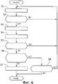
Фиг. 6 - это блок-схема последовательности операций, иллюстрирующая процесс управления определением положения колеса согласно первому варианту осуществления. В последующем, соответствующие этапы операции будут описаны. В последующем описании предполагается случай, когда ID датчика равен "1". Однако для других ID (ID=2, 3, 4), процесс управления определением положения колеса также выполняется параллельно.FIG. 6 is a flowchart illustrating a wheel position determination control process according to the first embodiment. Subsequently, the corresponding steps of the operation will be described. In the following description, it is assumed that the sensor ID is “1”. However, for other IDs (ID = 2, 3, 4), the wheel position determination control process is also performed in parallel.
На этапе S1 блок 4a вычисления углового положения принимает TPMS-данные с ID датчика, равным 1.In step S1, the angular position calculating unit 4a receives TPMS data with a sensor ID of 1.
На этапе S2 блок 4e запрещения обнаружения углового положения определяет, выполняется или нет управление торможением в текущий момент, и, если да, управление возвращается к этапу S1, если нет, управление переходит к этапу S3.In step S2, the angular position detection prohibition unit 4e determines whether or not the braking control is currently being performed, and if so, the control returns to step S1, if not, the control proceeds to step S3.
На этапе S3 секция 4a вычисления углового положения вычисляет угловое положение каждого колеса 1.In step S3, the angular position calculation section 4a calculates the angular position of each
[0026] На этапе S4 блок 4b вычисления дисперсии вычисляет значение X дисперсионной характеристики данных углового положения каждого колеса 1.[0026] In step S4, the dispersion calculating unit 4b calculates a value X of the dispersion characteristic of the angular position data of each
На этапе S5 выполняется определение относительно того, приняты ли TPMS-данные с ID датчика, равным 1, заданное число раз (например, 10 раз) или более. Если результатом определения является "Да", операция переходит к этапу S6. Если определением является "Нет", операция возвращается к этапу S1.In step S5, a determination is made as to whether the TPMS data with the sensor ID of 1 is received a predetermined number of times (e.g., 10 times) or more. If the determination result is “Yes”, the operation proceeds to step S6. If the determination is “No,” the operation returns to step S1.
На этапе S6 секция 4c определения положения колеса определяет, превышает или нет наибольшее значение значения характеристик первое пороговое значение 0,57, и меньше или нет значение оставшихся значений дисперсионных характеристик второго порогового значения 0,37. Если определением является "Да", операция переходит к этапу S7; если результатом определения является "Нет", операция переходит к этапу S8.In step S6, the wheel position determination section 4c determines whether or not the largest characteristic value exceeds the first threshold value of 0.57 and whether the remaining dispersion characteristic values of the second threshold value of 0.37 are less or not. If the determination is “Yes,” the operation proceeds to step S7; if the result of the determination is “No,” the operation proceeds to step S8.
[0027] На этапе S7 секция 4c определения положения колеса определяет положение колеса из данных углового положения, соответствующих наивысшему значению дисперсионной характеристики, в качестве положения колеса для ID датчика. Затем процесс автообучения заканчивается.[0027] In step S7, the wheel position determination section 4c determines the wheel position from the angular position data corresponding to the highest dispersion characteristic value as the wheel position for the sensor ID. Then the auto-learning process ends.
На этапе S8 секция 4c определения положения колеса определяет, прошло ли заданное совокупное или накопленное время движения (например, 8 мин) от начала режима автообучения. Если результатом определения является "Да", режим автообучения завершается. Если результатом определения является "Нет", операция возвращается к этапу S1.In step S8, the wheel position determining section 4c determines whether a predetermined cumulative or accumulated travel time (e.g., 8 minutes) has passed from the start of the auto-learning mode. If the result of the determination is “Yes,” the auto-learning mode ends. If the result of the determination is “No,” the operation returns to step S1.
Когда секция 4c определения положения колеса может определять положения колес для всех ID датчиков в течение заданного накопленного времени движения, соотношение соответствия между ID датчика и положением колеса обновляется и сохраняется в памяти 4d для регистрации. С другой стороны, когда невозможно определять положение колеса для всех ID датчиков в течение заданного накопленного времени движения, соотношение соответствия между множеством ID датчиков и положением каждого колеса, в настоящий момент сохраненное в памяти 4d, продолжает использоваться.When the wheel position determination section 4c can determine the wheel positions for all sensor IDs for a predetermined accumulated travel time, the correspondence relationship between the sensor ID and the wheel position is updated and stored in the memory 4d for registration. On the other hand, when it is not possible to determine the wheel position for all sensor IDs for a given accumulated travel time, the correlation relationship between the plurality of sensor IDs and the position of each wheel currently stored in the memory 4d continues to be used.
[0028] Далее поясняется процесс.[0028] Next, the process is explained.
[Операция определения положения колеса посредством степени дисперсии данных углового положения][Operation of determining the position of the wheel by the degree of dispersion of the data of the angular position]
TPMS-датчик 2 работает следующим образом: когда время определения остановки транспортного средства непосредственно перед началом движения транспортного средства составляет 15 мин или дольше, выполняется определение, что существует вероятность того, что выполнена перестановка шин, и операция переходит из обычного режима в режим передачи в постоянной позиции. В режиме передачи в постоянной позиции, после того как 16 секунд прошло от времени передачи в предыдущий раз, и угловое положение рассматриваемого TPMS-датчика достигает верхней точки, каждый TPMS-датчик 2 передает TPMS-данные.TPMS-
[0029] С другой стороны, когда прошедшее время между выключением и включением замка зажигания составляет 15 мин или дольше, TPMSCU 4 переходит из режима наблюдения в режим автообучения. В режиме автообучения, каждый раз когда TPMS-данные принимаются от каждого TPMS-датчика 2, TPMSCU 4 вычисляет угловое положение (число зубцов ротора) каждого колеса 1, когда угловое положение TPMS-датчика 2 достигает верхней точки, на основе времени ввода значения счетчика импульсов скорости колеса, времени завершения приема TPMS-данных и т.п. Это выполняется повторно 10 или более раз и накапливается в качестве данных углового положения. Среди данных углового положения положение колеса, данные углового положения которого имеют наименьшую степень дисперсии, определяется в качестве положения колеса этого TPMS-датчика 2.[0029] On the other hand, when the elapsed time between turning the ignition switch off and on is 15 minutes or longer, the
[0030] Когда транспортное средство перемещается или движется, скорости вращения каждого колеса 1 могут отличаться друг от друга вследствие различия в колеях между внешними и внутренними колесами, блокировки и проскальзывания колес 1 и различия в давлении воздуха в шинах. Даже когда транспортное средство движется прямо, поскольку водитель все еще может совершать мгновенные корректировки на рулевом колесе, и существует некоторое различие в поверхности дороги между левой и правой сторонами, различие в скорости вращения опять же развивается между передними и задними колесами 1FL и 1FR и между левыми и правыми колесами 1RL и 1RR. Т.е. пока существует различие в скорости вращения каждого колеса в соответствии с состоянием движения транспортного средства, поскольку TPMS-датчик 2 и датчик 8 скорости колеса (зубцы его ротора) вращаются вместе, в течение периода вывода конкретного TPMS-датчика 2, период вывода датчика 8 скорости колеса, ассоциированного с тем же колесом, сохраняется синхронизированным (согласующимся) независимо от расстояния перемещения и состояния движения.[0030] When the vehicle is moving or moving, the rotational speeds of each
[0031] Следовательно, наблюдая степень дисперсии в данных углового положения каждого колеса 1 относительно периода передачи TPMS-данных, возможно выполнить высокоточное определение по положениям колес каждого TPMS-датчика 2.[0031] Therefore, by observing the degree of dispersion in the angular position data of each
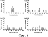
Фиг. 7 иллюстрирует соотношение между угловыми положениями (числом зубцов роторов) колес 1FL, 1FR, 1RL и 1RR, когда угловое положение TPMS-датчика 2FL левого переднего колеса 1FL достигает верхней точки, и числом случаев приема TPMS-данных. Здесь (a) соответствует датчику 8FL скорости колеса для левого переднего колеса 1FL, (b) соответствует датчику 8FR скорости колеса для правого переднего колеса 1FR, (c) соответствует датчику 8RL скорости колеса для левого заднего колеса 1RL и (d) соответствует датчику 8RR скорости колеса для правого заднего колеса 1RR.FIG. 7 illustrates the relationship between the angular positions (number of rotor teeth) of the wheels 1FL, 1FR, 1RL, and 1RR when the angular position of the TPMS sensor 2FL of the left front wheel 1FL reaches a high point and the number of times the TPMS data is received. Here (a) corresponds to the wheel speed sensor 8FL for the left front wheel 1FL, (b) corresponds to the wheel speed sensor 8FR for the right front wheel 1FR, (c) corresponds to the wheel speed sensor 8RL for the left rear wheel 1RL and (d) corresponds to the speed sensor 8RR wheels for the right rear wheel 1RR.
Как будет очевидно из фиг. 7, тогда как степени дисперсии являются высокими относительно положения колес (числа зубцов), полученных от датчиков 8FR, 8RL и 8RR скорости колеса относительно других колес (правого переднего колеса 1FR, левого заднего колеса 1RL и правого заднего колеса 1RR), степень дисперсии положения колеса, полученного от датчика 8FL скорости колеса относительно рассматриваемого колеса (левого переднего колеса 1FL) является минимальной или наименьшей, так что период вывода TPMS-датчика 2FL и период вывода датчика 8FL скорости колеса почти синхронизированы друг с другом.As will be apparent from FIG. 7, while the degree of dispersion is high relative to the position of the wheels (number of teeth) obtained from the wheel speed sensors 8FR, 8RL and 8RR relative to other wheels (right front wheel 1FR, left rear wheel 1RL and right rear wheel 1RR), the degree of dispersion of the wheel position received from the wheel speed sensor 8FL relative to the wheel in question (left front wheel 1FL) is minimal or smallest, so that the output period of the TPMS sensor 2FL and the output period of the wheel speed sensor 8FL are almost synchronized with each other ohm
[0032] В качестве одного из традиционных устройств контроля давления воздуха в шинах, датчик угла наклона размещается для каждого TPMS-датчика, и соотношение между положением колеса TPMS-датчика и углом наклона используется, чтобы определять положение колеса TPMS-датчика. Для этого типа устройства контроля давления воздуха в шине согласно движущемуся транспортному средству имеет место различие в скорости вращения между 4 колесами, так что соответствие между положением колеса TPMS-датчика и углом наклона изменяется. В результате невозможно выполнять высокоточное определение по положению колеса каждого TPMS-датчика.[0032] As one of the conventional tire pressure monitoring devices, a tilt angle sensor is arranged for each TPMS sensor, and a relationship between the position of the wheel of the TPMS sensor and the tilt angle is used to determine the position of the wheel of the TPMS sensor. For this type of tire pressure monitoring device according to a moving vehicle, there is a difference in rotational speed between 4 wheels, so that the correspondence between the position of the wheel of the TPMS sensor and the angle of inclination changes. As a result, it is not possible to perform a high-precision determination by the wheel position of each TPMS sensor.
В качестве другого традиционного устройства контроля давления воздуха в шинах, такое же число приемников, что и число TPMS-датчиков, размещаются рядом с датчиками, соответственно; на основе интенсивности электромагнитных волн принятых беспроводных сигналов определяется положение колеса каждого TPMS-датчика. Здесь необходимо учитывать вывод датчика, дисперсию чувствительности приемника и эффект от комплекта антенн для компоновки приемных устройств, и окружение приема и схема размещения определяют рабочие характеристики. Помимо этого должны размещаться 4 приемника. Следовательно, затраты являются более высокими.As another traditional device for monitoring tire pressure, the same number of receivers as the number of TPMS sensors are located next to the sensors, respectively; Based on the intensity of the electromagnetic waves of the received wireless signals, the wheel position of each TPMS sensor is determined. Here it is necessary to take into account the output of the sensor, the variance of the sensitivity of the receiver and the effect of the set of antennas for the layout of the receiving devices, and the environment of the reception and the layout determine the performance. In addition, 4 receivers should be placed. Therefore, the costs are higher.
С другой стороны, для устройства контроля давления воздуха в шинах в первом варианте осуществления положение колеса каждого TPMS-датчика 2 может быть указано без использования интенсивности электромагнитных волн, так что возможно определять положение колеса каждого TPMS-датчика 2 независимо от окружения приема и схемы размещения. Кроме того, достаточно одного приемника 3, что приводит к устранению затрат для дополнительных датчиков.On the other hand, for the tire pressure monitoring device in the first embodiment, the wheel position of each
[0033] Кроме того, согласно первому варианту осуществления TPMSCU 4 вычисляет и определяет, что угловое положение каждого колеса 1 позиционируется в верхней точке на основе зависимой от гравитационного ускорения компоненты ускорения в центробежном направлении, которая может быть обнаружена из G-датчика 2b. Поскольку G-датчик 2b используется в существующем устройстве контроля давления воздуха в шинах для обнаружения остановки и перемещения транспортного средства, существующий TPMS-датчик может быть использован в различных целях, так что нет необходимости добавлять новые датчики на стороне транспортного средства. Таким образом, затраты могут быть снижены.[0033] Furthermore, according to the first embodiment, the
[0034] [Операция при определении степени дисперсии из значения дисперсионной характеристики][0034] [Operation when determining the degree of dispersion from the value of the dispersion characteristic]
Поскольку угловое положение колеса 1 указывается угловыми данными с периодичностью, степень дисперсии углового положения не может быть определена с помощью общей дисперсионной формулы, определенной посредством среднего "квадрата разности из среднего числа или средней величины".Since the angular position of the
Таким образом, в первом варианте осуществления блок 4b вычисления дисперсии работает следующим образом. Угловое положение θ каждого колеса 1, полученное от каждого датчика 8 скорости колеса, преобразуется в окружные координаты (cos θ, sin θ) единичной окружности, имеющей исходную точку (0, 0) в центре. Координаты (cos θ, sin θ) принимаются в качестве векторов, получаются средние векторы (ave_cos θ, ave_sin θ) векторов одинаковых данных углового положения, и вычисляется скалярная величина среднего вектора в качестве значения X дисперсионной характеристики. В результате возможно избегать периодичности в определении степени дисперсии углового положения.Thus, in the first embodiment, the dispersion calculation unit 4b operates as follows. The angular position θ of each
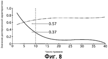
[0035] Фиг. 8 показывает схему, иллюстрирующую изменение в значении X дисперсионной характеристики в соответствии с числом приемов TPMS-данных. На фиг. 8 рассматриваемое колесо показывает значение X дисперсионной характеристики, вычисленное по данным углового положения датчика 8 скорости колеса на том же колесе, на котором установлен TPMS-датчик, тогда как другие колеса показывают значение X дисперсионной характеристики, вычисленное по данным углового положения датчика 8 скорости колеса на колесе, отличном от тех, на которых установлены TPMS-датчики.[0035] FIG. 8 is a diagram illustrating a change in the dispersion characteristic value X in accordance with the number of receptions of TPMS data. In FIG. 8, the wheel in question shows the dispersion characteristic value X calculated from the angular position of the wheel speed sensor 8 on the same wheel on which the TPMS sensor is mounted, while the other wheels show the dispersion characteristic value X calculated from the angular position of the wheel speed sensor 8 on a wheel other than those on which TPMS sensors are installed.
Как показано на фиг. 8, когда число приемов TPMS-данных по одному и тому же ID датчика увеличивается, указывается такая тенденция, в которой дисперсионная характеристика X приближается к "1", в то время как значение X дисперсионной характеристики для другого колеса приближается к "0". Таким образом, может быть идеальным выбирать максимальное значение (т.е. значение дисперсионной характеристики, самое близкое к "1") при достижении достаточного числа приемов (около нескольких десятков раз). Однако, поскольку невозможно сообщать водителю точную информацию о состоянии шин во время периода определения положения колеса непосредственно после перестановки шин, задержка во времени определения не является предпочтительной. С другой стороны, при недостаточном числе приемов (например, несколько раз), различие в значении дисперсионной характеристики относительно рассматриваемого и других колес не может быть обнаружено, и будет ожидаться уменьшение точности определения.As shown in FIG. 8, when the number of receptions of TPMS data for the same sensor ID increases, a trend is indicated in which the dispersion characteristic X approaches “1”, while the value X of the dispersion characteristic for the other wheel approaches “0”. Thus, it may be ideal to select the maximum value (ie, the value of the dispersion characteristic closest to "1") when a sufficient number of receptions (about several tens of times) is achieved. However, since it is not possible to provide the driver with accurate information about the condition of the tires during the period of determining the position of the wheel immediately after the tire is rearranged, a delay in the determination time is not preferable. On the other hand, with an insufficient number of receptions (for example, several times), a difference in the value of the dispersion characteristic relative to the considered and other wheels cannot be detected, and a decrease in the accuracy of determination will be expected.
[0036] Таким образом, в первом варианте осуществления блок 4c определения положения колеса сравнивает значения дисперсионных характеристик по каждым данным углового положения относительно конкретного ID датчика при приеме TPMS-данных относительно этого конкретного датчика десять раз или более и обнаруживает, что максимальное значение из значений X дисперсионной характеристики превышает первое пороговое значение 0,57, тогда как остальные три значения дисперсионной характеристики падают ниже второго порогового значения 0,37, затем положение колеса из данных углового положения, соответствующих максимальному значению X дисперсионной характеристики, будет идентифицировано в качестве положения колеса этого ID датчика.[0036] Thus, in the first embodiment, the wheel position determination unit 4c compares the dispersion characteristic values for each angular position data with respect to a particular sensor ID when receiving TPMS data regarding this specific sensor ten times or more and finds that the maximum value of the X values the dispersion characteristic exceeds the first threshold value of 0.57, while the other three values of the dispersion characteristic fall below the second threshold value of 0.37, then the position the forest from the angular position data corresponding to the maximum value X of the dispersion characteristic will be identified as the wheel position of this sensor ID.
Не только посредством выбора максимального значения из значений дисперсионной характеристики, но и сравнивая максимальное значение с первым пороговым значением (0,57), может быть гарантирована некоторая степень точности определения. Кроме того, сравнивая значения дисперсионной характеристики, отличные от максимального значения, со вторым пороговым значением (0,37), может быть подтверждена предварительно определенная разность (0,2 или более), что дополнительно улучшает точность определения. Следовательно, при относительно небольшом числе приемов, например, десять, могут быть достигнуты как точность определения, так и сокращение времени определения.Not only by choosing the maximum value from the values of the dispersion characteristic, but also comparing the maximum value with the first threshold value (0.57), a certain degree of accuracy of determination can be guaranteed. In addition, by comparing the dispersion characteristic values other than the maximum value with the second threshold value (0.37), a predetermined difference (0.2 or more) can be confirmed, which further improves the accuracy of the determination. Therefore, with a relatively small number of techniques, for example, ten, both accuracy of determination and reduction of determination time can be achieved.
[0037] [Операция прерывистой передачи TPMS-данных][0037] [Operation of discontinuous transmission of TPMS data]
Каждый TPMS-датчик 2 передает TPMS-данные, после того как прошло 16 секунд от предыдущего времени передачи TPMS-данных и в момент времени, в который рассматриваемое угловое положение достигает верхней точки. В первом варианте осуществления, поскольку значения X дисперсионной характеристики каждых данных углового положения сравниваются друг с другом для определения положения колеса относительно TPMS-датчика 2, который передал TPMS-данные, некоторая величина совокупного расстояния перемещения будет необходима для того, чтобы вызывать различие в значениях X дисперсионной характеристики между рассматриваемым колесом (тем же колесом) и другим колесом (другим колесом транспортного средства).Each
Предположим, что TPMS-данные передавались бы каждый раз, когда угловое положение TPMS-данных достигает верхней точки, никакого существенного различия в значении дисперсионной характеристики не будет ожидаться между рассматриваемым и другим колесом, так что может быть затруднительным выполнять определение положения колеса.Assuming that the TPMS data would be transmitted each time the angular position of the TPMS data reaches a high point, no significant difference in the value of the dispersion characteristic would be expected between the considered and the other wheel, so it may be difficult to determine the position of the wheel.
Таким образом, устанавливая интервал передачи в 16 секунд + α, некоторая величина совокупного интервала перемещения будет получена, пока TPMS-данные не будут приняты десять раз или более. Следовательно, достаточное различие в значении X дисперсионной характеристики между рассматриваемым и другим колесом может быть создано, чтобы гарантировать точное определение положения колеса.Thus, setting the transmission interval to 16 seconds + α, a certain value of the cumulative movement interval will be obtained until the TPMS data is received ten times or more. Therefore, a sufficient difference in the X value of the dispersion characteristic between the considered and the other wheel can be created to ensure accurate determination of the position of the wheel.
[0038] [Операция уменьшения потребления энергии][0038] [Operation to reduce energy consumption]
При приеме TPMS-данных сорок (40) раз во время режима передачи в постоянной позиции TPMS-датчик 2 переходит в обычный режим. TPMS-датчик 2 потребляет энергию батареи 2e таблеточного типа при передаче TPMS-данных, так что срок эксплуатации батареи для батареи 2e таблеточного типа будет короче, поскольку режим передачи в постоянной позиции продолжается. Таким образом, когда положение каждого колеса не может быть определено, несмотря на прохождение достаточного совокупного времени перемещения, режим передачи в постоянной позиции будет завершен, чтобы переходить в обычный режим, что может пресекать сокращение срока эксплуатации батареи.When receiving TPMS data forty (40) times during the transmission mode in the constant position, the
С другой стороны, когда TPMSCU 4 не может определить соответствие между ID каждого датчика и положением каждого колеса, несмотря на прошедшее время совокупного перемещения в восемь (8) минут, режим автообучения будет завершен, и процесс переходит в режим наблюдения. Общее число TPMS-данных составляет тридцать (30) раз или менее, когда прошло совокупное время перемещения в восемь минут, режим автообучения может быть завершен, по существу, синхронно с завершением режима передачи в постоянной позиции TPMS-датчика 2.On the other hand, when
[0039] [Операция пресечения задержки определения положения колеса][0039] [Operation to suppress the delay in determining the position of the wheel]
CU 2с датчика для TPMS-датчика 2 определяет угловое положение TPMS-датчика 2 на основе зависимой от гравитационного ускорения компоненты центробежного ускорения, определенного посредством G-датчика 2b, во время режима передачи в постоянной позиции и передает TPMS-данные на пике зависимой от гравитационного ускорения компоненты, так что TPMS-данные будут передаваться в верхней точке во все моменты времени передачи. Хотя центробежное ускорение, влияющее на TPMS-датчик 2, может быть подвержено изменению вследствие ускорения/замедления колеса 1, зависимая от гравитационного ускорения компонента постоянно получает форму волны постоянной ширины (от -1 до 1 [G]) и изменения с чрезвычайно более коротким периодом по сравнению со скоростью изменения в центробежном ускорении, сопровождаемом ускорением/замедлением транспортного средства. Следовательно, легко улавливать изменение в зависимой от гравитационного ускорения компоненте на основе центробежных ускорений.The
[0040] Однако, когда управление торможением, такое как ABS-управление и антипробуксовочное управление с использованием тормоза, выполняется, колесо 1 под управлением подвержено колебанию в продольном направлении в очень коротком периоде вследствие этого управления, на центробежное ускорение, обнаруженное посредством G-датчика 2b, будет оказываться влияние, и оно будет колебаться в очень коротком периоде с большой шириной или амплитудой (несколько десятков [G] или более). Таким образом, CU 2c датчика может ложно определять колебания или флуктуации как пик в зависимой от гравитационного ускорения компоненте, так что существует вероятность того, что TPMS-данные будут передаваться в угловом положении, отличном от пика.[0040] However, when braking control, such as ABS control and traction control using the brake, is performed, the
Таким образом, блок 4a вычисления углового положения TPMSCU 4 вычисляет угловое положение каждого колеса 1 в момент времени, в который угловое положение каждого TPMS-датчика 2 достигло своего пика, на основе момента времени приема TPMS-данных и значения счетчика импульсов скорости колеса для каждого колеса в этот момент времени. Следовательно, блок 4a вычисления углового положения вычисляет угловое положение каждого колеса 1, которое было передано в угловом положении, отличном от верхней точки, как угловое положение, переданное в верхней точке, и блок 4b вычисления дисперсии должен вычислять значение X дисперсионной характеристики для каждого колеса 1, включая это угловое положение в данные углового положения. Следовательно, вследствие включения ложных данных углового положения в данные углового положения для каждого колеса, формирование различия между максимальным значением и другими значениями для каждого значения X дисперсионной характеристики будет задерживаться, и определение положения колеса будет задерживаться.Thus, the angular position calculating unit 4a of the
[0041] В отличие от этого, в первом варианте осуществления блок 4e запрещения обнаружения углового положения запрещает блоку 4a вычисления углового положения обнаруживать угловое положение для каждого колеса, когда выполняется управление торможением, такое как ABS-управление.[0041] In contrast, in the first embodiment, the angular position detection prohibition unit 4e prohibits the angular position calculation unit 4a from detecting the angular position for each wheel when braking control such as ABS control is performed.
Более конкретно, когда существует вероятность того, что момент передачи TPMS-данных отличается от нормального или обычного момента передачи, посредством запрещения вычисления углового положения каждого колеса на основе этих TPMS-данных вычисление значения X дисперсионной характеристики с использованием ошибочных или ложных данных будет пресекаться.More specifically, when it is likely that the moment of transmission of the TPMS data differs from the normal or normal moment of transmission, by prohibiting the calculation of the angular position of each wheel based on this TPMS data, the calculation of the dispersion characteristic value X using erroneous or false data will be suppressed.
Другими словами, когда существует вероятность того, что момент времени передачи TPMS-данных реализован как момент времени, отличный от нормального или обычного момента, тогда посредством запрещения вычисления углового положения каждого колеса 1 будет предотвращено включение ошибочных данных углового положения в данные углового положения для каждого колеса. Следовательно, задержка в определении положения колеса будет подавлена, и соотношение соответствия между ID каждого датчика и положением каждого колеса может быть определено на раннем этапе.In other words, when there is a possibility that the transmission time point of the TPMS data is implemented as a timing other than the normal or normal moment, then by inhibiting the calculation of the angular position of each
[0042] Теперь выполняется описание результатов.[0042] A description of the results is now performed.
В устройстве контроля давления воздуха в шинах в первом варианте осуществления достигаются следующие результаты.In the tire pressure monitoring device in the first embodiment, the following results are achieved.
(1) В устройстве контроля давления воздуха в шинах, которое наблюдает за давлением воздуха каждой шины, предусмотрены датчик 2a давления, который обнаруживает давление воздуха шины, и который установлен на шине каждого колеса 1; датчик 2a давления для обнаружения давления воздуха шины; G-датчик 2b, который установлен на шине каждого колеса 1 и обнаруживает центробежное ускорение, действующее на шину; и передатчик 2d, который установлен на каждом колесе 1 и измеряет угловое положение колеса на основе обнаруженного значения G-датчика 2b, чтобы передавать в качестве беспроводного сигнала давление воздуха в заданном угловом положении вместе с ID датчика; приемник 3, который размещен на стороне кузова транспортного средства и принимает беспроводной сигнал, блок 4a вычисления углового положения, установленный на стороне кузова транспортного средства и определяющий угловое положение каждого колеса 1, когда беспроводной сигнал включает в себя ID конкретного датчика, блок 4c определения положения колеса, который определяет положение колеса передатчика, соответствующего этому конкретному ID датчика, на основе углового положения каждого колеса 1, и блок 4e запрещения обнаружения углового положения, который запрещает обнаружение углового положения каждого колеса 1 блоком 4a вычисления углового положения.(1) In a tire air pressure monitoring device that monitors the air pressure of each tire, a
Таким образом, задержка в определении положения колеса вследствие колебания колеса 1, вызванного управлением торможением, может быть пресечена, и соответствие между ID каждого датчика и положением каждого колеса может быть своевременно установлено.Thus, the delay in determining the position of the wheel due to the oscillation of the
[0043] (2) Блок 4c определения положения колеса получает угловое положение для каждого колеса 1 множество раз, накапливает данные углового положения для каждого колеса и определяет положение колеса, соответствующее данным углового положения с наименьшей степенью дисперсии среди данных углового положения, как положение колеса передатчика 3, соответствующего ID конкретного датчика.[0043] (2) The wheel position determination unit 4c obtains an angular position for each
Таким образом, соотношение соответствия между каждым TPMS-датчиком 2 и положением каждого колеса может быть определено с высокой точностью.Thus, the correspondence relationship between each
[0044] (3) G-датчик 2b обнаруживает центробежное ускорение, оказываемое на шину, в то время как TPMS-датчик 2 обнаруживает угловое положение колеса на основе зависимой от гравитационного ускорения компоненты центробежного ускорения.[0044] (3) The G-
Таким образом, даже в состоянии ускорения/замедления транспортного средства угловое положение колеса может быть обнаружено с хорошей точностью.Thus, even in the vehicle acceleration / deceleration state, the angular position of the wheel can be detected with good accuracy.
[0045] [Другие варианты осуществления][0045] [Other embodiments]
В то время как лучшие варианты осуществления описаны, чтобы реализовывать настоящее изобретение, конкретная конфигурация не ограничена этими вариантами осуществления. Наоборот, изменение конструкции или модификации, которые не отступают от сущности настоящего изобретения, могут быть включены в настоящее изобретение.While the best embodiments have been described to implement the present invention, the specific configuration is not limited to these embodiments. Conversely, a design change or modification that does not depart from the spirit of the present invention may be included in the present invention.
Например, G-датчик может обнаруживать ускорение, оказываемое в направлении вращения шины, и обнаруживает угловое положение по этому обнаруженному ускорению. Во время постоянного движения транспортного средства, при котором ускорение/замедление не возникает в направлении вращения шины, ускорение, действующее на шину, равно "0" [G] либо вверху, либо внизу шины, при этом предполагается равным "1" [G] или "-1" [G] в переднем и обратном направлении, соответственно. Следовательно, передавая TPMS-данные в момент времени, когда обнаруженное значение датчика ускорения предполагается равным "1" или "-1", TPMS-данные могут передаваться в постоянном угловом положении.For example, the G-sensor can detect acceleration in the tire rotation direction, and detects an angular position from this detected acceleration. During the continuous movement of the vehicle, in which acceleration / deceleration does not occur in the direction of rotation of the tire, the acceleration acting on the tire is “0” [G] either above or below the tire, it is assumed to be “1” [G] or "-1" [G] in the forward and reverse directions, respectively. Therefore, by transmitting TPMS data at a time when the detected value of the acceleration sensor is assumed to be “1” or “-1”, the TPMS data can be transmitted in a constant angular position.
Claims (6)
датчик давления воздуха в шине, установленный на шине каждого колеса, чтобы обнаруживать давление воздуха в шине, действующее на шину;
датчик ускорения, установленный на шине каждого колеса, чтобы обнаруживать ускорение в заданном направлении, действующее на шину;
передатчик, размещенный на каждом колесе, чтобы обнаруживать угловое положение колеса на основе обнаруженного значения датчика ускорения, для передачи давления воздуха вместе с идентификационной информацией, уникальной для каждого передатчика, через беспроводной сигнал;
приемник, установленный на кузове транспортного средства, чтобы принимать беспроводной сигнал;
блок обнаружения углового положения, установленный на кузове транспортного средства, чтобы обнаруживать угловое положение каждого колеса, когда конкретная идентификационная информация была передана;
блок определения положения колеса, который получает угловое положение каждого колеса множество раз, чтобы накапливать данные углового положения для каждого колеса, и определяет положение колеса, соответствующее данным углового положения с наименьшей степенью дисперсии среди данных углового положения, как положение колеса передатчика, соответствующего конкретной идентификационной информации; и
блок запрещения обнаружения, который запрещает накопление данных углового положения каждого колеса блоком обнаружения положения колеса, когда выполняется управление торможением, чтобы управлять давлением рабочего тормозного цилиндра колеса.1. A device for monitoring tire pressure, comprising:
a tire air pressure sensor mounted on the tire of each wheel to detect tire pressure acting on the tire;
an acceleration sensor mounted on the tire of each wheel to detect acceleration in a predetermined direction acting on the tire;
a transmitter located on each wheel to detect the angular position of the wheel based on the detected value of the acceleration sensor for transmitting air pressure together with identification information unique to each transmitter through a wireless signal;
a receiver mounted on the vehicle body to receive a wireless signal;
an angular position detection unit mounted on the vehicle body to detect an angular position of each wheel when specific identification information has been transmitted;
a wheel position determining unit that obtains the angular position of each wheel many times to accumulate angular position data for each wheel, and determines a wheel position corresponding to the angular position data with the least degree of dispersion among the angular position data as the position of the transmitter wheel corresponding to the specific identification information ; and
a detection inhibiting unit that prohibits the accumulation of angular position data of each wheel by the wheel position detecting unit when braking control is performed to control the pressure of the working brake cylinder of the wheel.
датчик давления воздуха в шине, установленный на шине каждого колеса, чтобы обнаруживать давление воздуха в шине, действующее на шину;
датчик ускорения, установленный на шине каждого колеса, чтобы обнаруживать ускорение в заданном направлении, действующее на шину;
передатчик, размещенный на каждом колесе, чтобы обнаруживать угловое положение колеса на основе обнаруженного значения датчика ускорения, для передачи давления воздуха вместе с идентификационной информацией, уникальной для каждого передатчика, через беспроводной сигнал;
приемник, установленный на кузове транспортного средства, чтобы принимать беспроводной сигнал;
блок обнаружения углового положения, установленный на кузове транспортного средства, чтобы обнаруживать угловое положение каждого колеса, когда конкретная идентификационная информация была передана;
блок определения положения колеса, который получает угловое положение каждого колеса множество раз, чтобы накапливать данные углового положения для каждого колеса, и определяет положение колеса, соответствующее данным углового положения с наименьшей степенью дисперсии среди данных углового положения, как положение колеса передатчика, соответствующего конкретной идентификационной информации; и
блок запрещения обнаружения, который запрещает обнаруживать угловое положение каждого колеса посредством блока обнаружения углового положения, когда выполняется управление торможением, чтобы управлять давлением рабочего тормозного цилиндра колеса, при этом
блок определения положения колеса сконфигурирован так, чтобы преобразовывать угловое положение колеса в вектор на двухмерной плоскости с собственной исходной точкой в качестве начальной точки и окружной точкой единичной окружности в качестве конечной точки, вычислять скалярную величину среднего вектора каждых данных углового положения в качестве значения дисперсионной характеристики и определять максимальное значение каждого значения дисперсионной характеристики как значение с наименьшей степенью дисперсии.2. A device for monitoring tire pressure, comprising:
a tire air pressure sensor mounted on the tire of each wheel to detect tire pressure acting on the tire;
an acceleration sensor mounted on the tire of each wheel to detect acceleration in a predetermined direction acting on the tire;
a transmitter located on each wheel to detect the angular position of the wheel based on the detected value of the acceleration sensor for transmitting air pressure together with identification information unique to each transmitter through a wireless signal;
a receiver mounted on the vehicle body to receive a wireless signal;
an angular position detection unit mounted on the vehicle body to detect an angular position of each wheel when specific identification information has been transmitted;
a wheel position determining unit that obtains the angular position of each wheel many times to accumulate angular position data for each wheel, and determines a wheel position corresponding to the angular position data with the least degree of dispersion among the angular position data as the position of the transmitter wheel corresponding to the specific identification information ; and
a detection inhibiting unit that prohibits detecting the angular position of each wheel by the angular position detecting unit when braking control is performed to control the pressure of the working brake cylinder of the wheel,
the wheel position determination unit is configured to convert the wheel angular position to a vector on a two-dimensional plane with its own starting point as a starting point and a unit circumference point as an end point, calculating a scalar value of the average vector of each angular position data as a value of the dispersion characteristic and determine the maximum value of each value of the dispersion characteristic as the value with the least degree of dispersion.
управление торможением является антиблокировочным управлением торможением, в котором колесо с тенденцией блокировки сдерживается посредством регулирования давления рабочего тормозного цилиндра колеса.3. The tire pressure monitoring device according to claim 2, in which
braking control is anti-lock braking control in which a wheel with a tendency to lock is held back by adjusting the pressure of the working brake cylinder of the wheel.
управление торможением является управлением стабильностью поведения транспортного средства, чтобы обеспечивать стабильность вождения транспортного средства, при которой транспортное средство с тенденцией избыточного рулевого управления или недостаточного рулевого управления сдерживается посредством передачи тормозного усилия колесу.4. The device for monitoring tire pressure according to claim 2, in which
braking control is controlling the stability of the behavior of the vehicle in order to ensure stability of driving of the vehicle in which a vehicle with a tendency of excessive steering or insufficient steering is restrained by transmitting the braking force to the wheel.
управление торможением является антипробуксовочным управлением с использованием тормоза в ответ на холостое вращение ведущего колеса, чтобы пресекать холостое вращение ведущего колеса и увеличивать силу сцепления шины.5. The device for monitoring air pressure in tires according to claim 2, in which
braking control is traction control using the brake in response to idle rotation of the drive wheel in order to suppress idle rotation of the drive wheel and increase the traction of the tire.
управление торможением является управлением ограничения дифференциала с использованием тормоза, чтобы ограничивать дифференциал с помощью тормоза. 6. The tire pressure monitoring device according to claim 2, in which
braking control is a differential limitation control using a brake to limit the differential using a brake.
Applications Claiming Priority (3)
| Application Number | Priority Date | Filing Date | Title |
|---|---|---|---|
| JP2011096674A JP5853402B2 (en) | 2011-04-25 | 2011-04-25 | Tire pressure monitoring device |
| JP2011-096674 | 2011-04-25 | ||
| PCT/JP2012/053972 WO2012147395A1 (en) | 2011-04-25 | 2012-02-20 | Tire air pressure monitor device |
Publications (2)
| Publication Number | Publication Date |
|---|---|
| RU2550107C1 true RU2550107C1 (en) | 2015-05-10 |
| RU2013152161A RU2013152161A (en) | 2015-05-27 |
Family
ID=47071923
Family Applications (1)
| Application Number | Title | Priority Date | Filing Date |
|---|---|---|---|
| RU2013152161/11A RU2550107C1 (en) | 2011-04-25 | 2012-02-20 | Device to control air pressure in tyres |
Country Status (10)
| Country | Link |
|---|---|
| US (1) | US8943882B2 (en) |
| EP (1) | EP2703192B1 (en) |
| JP (1) | JP5853402B2 (en) |
| KR (1) | KR101477949B1 (en) |
| CN (1) | CN103492199B (en) |
| BR (1) | BR112013027401B1 (en) |
| MX (1) | MX2013011757A (en) |
| MY (1) | MY163967A (en) |
| RU (1) | RU2550107C1 (en) |
| WO (1) | WO2012147395A1 (en) |
Cited By (2)
| Publication number | Priority date | Publication date | Assignee | Title |
|---|---|---|---|---|
| RU181539U1 (en) * | 2017-08-01 | 2018-07-18 | Федеральное государственное бюджетное образовательное учреждение высшего образования "Петрозаводский государственный университет" | WHEEL LOCK ALARM ON A MOVING VEHICLE |
| WO2023014239A1 (en) * | 2021-08-04 | 2023-02-09 | Михаил Михайлович ЗАКАТОВ | Passive gauge for measuring air parameters in tyres and the angular velocity of wheels |
Families Citing this family (18)
| Publication number | Priority date | Publication date | Assignee | Title |
|---|---|---|---|---|
| RU2543131C1 (en) * | 2011-04-15 | 2015-02-27 | Ниссан Мотор Ко., Лтд. | Device for tire air pressure monitoring |
| JP5736948B2 (en) | 2011-05-13 | 2015-06-17 | 日産自動車株式会社 | Tire pressure monitoring system |
| JP2015020481A (en) * | 2013-07-17 | 2015-02-02 | トヨタ自動車株式会社 | Wheel information acquisition device |
| JP6257992B2 (en) * | 2013-10-10 | 2018-01-10 | 太平洋工業株式会社 | Tire position determination system |
| JP2015131546A (en) * | 2014-01-10 | 2015-07-23 | 株式会社東海理化電機製作所 | Tire position registration system |
| JP6372226B2 (en) * | 2014-07-30 | 2018-08-15 | 株式会社デンソー | Wheel position detecting device and tire air pressure detecting device having the same |
| TWI558579B (en) * | 2014-10-01 | 2016-11-21 | 財團法人工業技術研究院 | Tire positioning method and tire positioning system |
| FR3028058B1 (en) * | 2014-10-30 | 2016-12-09 | Continental Automotive France | METHOD FOR CONTROLLING A PROCESSOR OF AN ELECTRONIC HOUSING MOUNTED ON A WHEEL OF A MOTOR VEHICLE |
| DE102015216692A1 (en) * | 2015-09-01 | 2017-03-02 | Continental Automotive Gmbh | Electronic wheel unit for a vehicle wheel, and method for operating such an electronic wheel unit |
| WO2017042911A1 (en) * | 2015-09-09 | 2017-03-16 | 太平洋工業 株式会社 | Wheel position determination device |
| CN106626993A (en) * | 2016-12-22 | 2017-05-10 | 深圳市车生活科技有限公司 | TPMS (tire pressure monitor system) tire detection system and method |
| CN109153298B (en) * | 2017-04-27 | 2020-11-03 | 太平洋工业株式会社 | Receiver and transmitter unit |
| CN108583170B (en) * | 2018-05-23 | 2021-01-05 | 浙江吉利汽车研究院有限公司 | Tire self-positioning system and method |
| CN108973541A (en) * | 2018-06-01 | 2018-12-11 | 上海汽车集团股份有限公司 | Utilize the method for tire pressure monitoring sensor positioning entire vehicle tyre position |
| CN108944281A (en) * | 2018-07-25 | 2018-12-07 | 合肥市智信汽车科技有限公司 | Monitoring system built in a kind of wheel |
| CN108909378A (en) * | 2018-07-26 | 2018-11-30 | 宁波琻捷电子科技有限公司 | Vehicle tyre localization method and system |
| DE102018126620A1 (en) * | 2018-10-25 | 2020-04-30 | Huf Baolong Electronics Bretten Gmbh | Tire pressure monitoring system |
| CN110667317B (en) * | 2019-11-07 | 2021-06-15 | 中国民航大学 | Wheel position positioning method based on acceleration data |
Citations (1)
| Publication number | Priority date | Publication date | Assignee | Title |
|---|---|---|---|---|
| JP2010122023A (en) * | 2008-11-19 | 2010-06-03 | Nissan Motor Co Ltd | Device and method for monitoring tire pressure |
Family Cites Families (23)
| Publication number | Priority date | Publication date | Assignee | Title |
|---|---|---|---|---|
| JPH06286430A (en) * | 1993-03-30 | 1994-10-11 | Mazda Motor Corp | Tire pneumatic pressure alarm device |
| JP3286004B2 (en) * | 1993-03-29 | 2002-05-27 | マツダ株式会社 | Tire pressure warning device |
| US5826210A (en) | 1993-03-29 | 1998-10-20 | Mazda Motor Corporation | Tire air pressure warining device |
| JP3119809B2 (en) * | 1996-01-26 | 2000-12-25 | 住友電気工業株式会社 | Method and apparatus for detecting decrease in tire air pressure |
| DE19734323B4 (en) * | 1997-08-08 | 2004-05-06 | Continental Aktiengesellschaft | Method for carrying out the assignment of the wheel position to tire pressure control devices in a tire pressure control system of a motor vehicle |
| AU5564999A (en) * | 1999-08-16 | 2001-03-13 | Goodyear Tire And Rubber Company, The | Monitoring a dynamic condition of a rotary element, particularly a pneumatic tire |
| EP1227018B1 (en) * | 2001-01-29 | 2005-10-19 | The Goodyear Tire & Rubber Company | Monitoring pneumatic tire conditions |
| JP4114044B2 (en) * | 2001-07-17 | 2008-07-09 | トヨタ自動車株式会社 | Tire acting force detection device |
| ES2316852T3 (en) * | 2002-08-30 | 2009-04-16 | Bridgestone Corporation | MONITORING SYSTEM OF THE STATE OF THE WHEELS. |
| FR2847667B1 (en) * | 2002-11-22 | 2005-01-07 | Siemens Vdo Automotive | DEVICE FOR DETECTING THE POSITION OF A VEHICLE WHEEL |
| DE102004024388B4 (en) * | 2004-05-17 | 2006-07-06 | Siemens Ag | Vehicle wheel`s position determining device, has evaluation device for determining position of wheel based on disturbing components of acceleration signal that is caused by unevenness of road surface |
| JP2006138803A (en) * | 2004-11-15 | 2006-06-01 | Toyota Motor Corp | Apparatus for acquiring wheel condition and method of communicating wheel condition |
| BRPI0722313B1 (en) * | 2007-12-20 | 2020-09-15 | Pirelli Tyre S.P.A. | METHOD FOR MANAGING DATA TRANSMISSION FROM A PLURALITY OF SENSOR DEVICES INCLUDED IN A TIRE MOUNTED IN A VEHICLE AND SYSTEM TO MANAGE A TIRE MOUNTED IN A VEHICLE |
| JP4462365B2 (en) * | 2008-03-19 | 2010-05-12 | 株式会社デンソー | Tire pressure detector |
| JP2011058967A (en) * | 2009-09-10 | 2011-03-24 | Sanyo Electric Co Ltd | Correction device for acceleration sensor |
| CN102666147A (en) * | 2009-09-22 | 2012-09-12 | 施拉德电子有限公司 | System and method for performing auto-location of a wheel in a vehicle using wheel phase angle information |
| CN101973192B (en) * | 2010-10-03 | 2013-01-30 | 燕山大学 | Method for monitoring tire pressure during corning process of automobile |
| KR101560960B1 (en) * | 2011-04-25 | 2015-10-15 | 닛산 지도우샤 가부시키가이샤 | Tire air pressure transmission device and tire air pressure monitor system |
| JP5736948B2 (en) * | 2011-05-13 | 2015-06-17 | 日産自動車株式会社 | Tire pressure monitoring system |
| JP5803733B2 (en) * | 2012-02-23 | 2015-11-04 | 株式会社デンソー | Tire pressure detection device with wheel position detection function |
| JP2014080176A (en) * | 2012-09-25 | 2014-05-08 | Tokai Rika Co Ltd | Tire position discrimination system |
| JP2014128982A (en) * | 2012-12-27 | 2014-07-10 | Tokai Rika Co Ltd | Tire position determination system |
| JP2015013637A (en) * | 2013-06-03 | 2015-01-22 | 株式会社東海理化電機製作所 | Tire position determination system |
-
2011
- 2011-04-25 JP JP2011096674A patent/JP5853402B2/en active Active
-
2012
- 2012-02-20 MX MX2013011757A patent/MX2013011757A/en active IP Right Grant
- 2012-02-20 RU RU2013152161/11A patent/RU2550107C1/en active
- 2012-02-20 KR KR1020137027780A patent/KR101477949B1/en active IP Right Grant
- 2012-02-20 CN CN201280017720.8A patent/CN103492199B/en active Active
- 2012-02-20 MY MYPI2013003826A patent/MY163967A/en unknown
- 2012-02-20 WO PCT/JP2012/053972 patent/WO2012147395A1/en active Application Filing
- 2012-02-20 BR BR112013027401-8A patent/BR112013027401B1/en active IP Right Grant
- 2012-02-20 EP EP12777592.2A patent/EP2703192B1/en active Active
- 2012-02-20 US US14/113,174 patent/US8943882B2/en active Active
Patent Citations (1)
| Publication number | Priority date | Publication date | Assignee | Title |
|---|---|---|---|---|
| JP2010122023A (en) * | 2008-11-19 | 2010-06-03 | Nissan Motor Co Ltd | Device and method for monitoring tire pressure |
Cited By (2)
| Publication number | Priority date | Publication date | Assignee | Title |
|---|---|---|---|---|
| RU181539U1 (en) * | 2017-08-01 | 2018-07-18 | Федеральное государственное бюджетное образовательное учреждение высшего образования "Петрозаводский государственный университет" | WHEEL LOCK ALARM ON A MOVING VEHICLE |
| WO2023014239A1 (en) * | 2021-08-04 | 2023-02-09 | Михаил Михайлович ЗАКАТОВ | Passive gauge for measuring air parameters in tyres and the angular velocity of wheels |
Also Published As
| Publication number | Publication date |
|---|---|
| CN103492199B (en) | 2016-07-06 |
| EP2703192B1 (en) | 2016-08-24 |
| RU2013152161A (en) | 2015-05-27 |
| US8943882B2 (en) | 2015-02-03 |
| BR112013027401B1 (en) | 2021-01-19 |
| US20140076040A1 (en) | 2014-03-20 |
| JP5853402B2 (en) | 2016-02-09 |
| BR112013027401A2 (en) | 2017-01-17 |
| WO2012147395A1 (en) | 2012-11-01 |
| KR20130130080A (en) | 2013-11-29 |
| EP2703192A4 (en) | 2015-03-18 |
| JP2012228892A (en) | 2012-11-22 |
| EP2703192A1 (en) | 2014-03-05 |
| MY163967A (en) | 2017-11-15 |
| KR101477949B1 (en) | 2014-12-30 |
| MX2013011757A (en) | 2014-02-11 |
| CN103492199A (en) | 2014-01-01 |
Similar Documents
| Publication | Publication Date | Title |
|---|---|---|
| RU2550107C1 (en) | Device to control air pressure in tyres | |
| RU2554164C1 (en) | Device for tire air pressure monitoring | |
| RU2536001C1 (en) | Tire air pressure transfer device and tire air pressure control system | |
| RU2549577C1 (en) | Tire air pressure monitoring device | |
| KR101560468B1 (en) | Tire air pressure monitoring device | |
| RU2542854C1 (en) | Tire air pressure control device | |
| JP5736951B2 (en) | Tire pressure monitoring device | |
| JP5741765B2 (en) | Tire pressure monitoring device | |
| WO2013132967A1 (en) | Tire air pressure monitor device | |
| JP5741766B2 (en) | Tire pressure monitoring device | |
| JP5741768B2 (en) | Tire pressure monitoring device | |
| WO2013133309A1 (en) | Tire air pressure monitor device |