BR112013027401B1 - pneumatic tire pressure monitoring device - Google Patents
pneumatic tire pressure monitoring device Download PDFInfo
- Publication number
- BR112013027401B1 BR112013027401B1 BR112013027401-8A BR112013027401A BR112013027401B1 BR 112013027401 B1 BR112013027401 B1 BR 112013027401B1 BR 112013027401 A BR112013027401 A BR 112013027401A BR 112013027401 B1 BR112013027401 B1 BR 112013027401B1
- Authority
- BR
- Brazil
- Prior art keywords
- wheel
- rotational position
- sensor
- tpms
- data
- Prior art date
Links
Images


Classifications
-
- B—PERFORMING OPERATIONS; TRANSPORTING
- B60—VEHICLES IN GENERAL
- B60C—VEHICLE TYRES; TYRE INFLATION; TYRE CHANGING; CONNECTING VALVES TO INFLATABLE ELASTIC BODIES IN GENERAL; DEVICES OR ARRANGEMENTS RELATED TO TYRES
- B60C23/00—Devices for measuring, signalling, controlling, or distributing tyre pressure or temperature, specially adapted for mounting on vehicles; Arrangement of tyre inflating devices on vehicles, e.g. of pumps or of tanks; Tyre cooling arrangements
- B60C23/02—Signalling devices actuated by tyre pressure
- B60C23/04—Signalling devices actuated by tyre pressure mounted on the wheel or tyre
- B60C23/0408—Signalling devices actuated by tyre pressure mounted on the wheel or tyre transmitting the signals by non-mechanical means from the wheel or tyre to a vehicle body mounted receiver
- B60C23/0415—Automatically identifying wheel mounted units, e.g. after replacement or exchange of wheels
- B60C23/0416—Automatically identifying wheel mounted units, e.g. after replacement or exchange of wheels allocating a corresponding wheel position on vehicle, e.g. front/left or rear/right
-
- B—PERFORMING OPERATIONS; TRANSPORTING
- B60—VEHICLES IN GENERAL
- B60C—VEHICLE TYRES; TYRE INFLATION; TYRE CHANGING; CONNECTING VALVES TO INFLATABLE ELASTIC BODIES IN GENERAL; DEVICES OR ARRANGEMENTS RELATED TO TYRES
- B60C23/00—Devices for measuring, signalling, controlling, or distributing tyre pressure or temperature, specially adapted for mounting on vehicles; Arrangement of tyre inflating devices on vehicles, e.g. of pumps or of tanks; Tyre cooling arrangements
- B60C23/02—Signalling devices actuated by tyre pressure
- B60C23/04—Signalling devices actuated by tyre pressure mounted on the wheel or tyre
- B60C23/0486—Signalling devices actuated by tyre pressure mounted on the wheel or tyre comprising additional sensors in the wheel or tyre mounted monitoring device, e.g. movement sensors, microphones or earth magnetic field sensors
- B60C23/0488—Movement sensor, e.g. for sensing angular speed, acceleration or centripetal force
-
- B—PERFORMING OPERATIONS; TRANSPORTING
- B60—VEHICLES IN GENERAL
- B60C—VEHICLE TYRES; TYRE INFLATION; TYRE CHANGING; CONNECTING VALVES TO INFLATABLE ELASTIC BODIES IN GENERAL; DEVICES OR ARRANGEMENTS RELATED TO TYRES
- B60C23/00—Devices for measuring, signalling, controlling, or distributing tyre pressure or temperature, specially adapted for mounting on vehicles; Arrangement of tyre inflating devices on vehicles, e.g. of pumps or of tanks; Tyre cooling arrangements
- B60C23/02—Signalling devices actuated by tyre pressure
- B60C23/04—Signalling devices actuated by tyre pressure mounted on the wheel or tyre
- B60C23/0486—Signalling devices actuated by tyre pressure mounted on the wheel or tyre comprising additional sensors in the wheel or tyre mounted monitoring device, e.g. movement sensors, microphones or earth magnetic field sensors
- B60C23/0489—Signalling devices actuated by tyre pressure mounted on the wheel or tyre comprising additional sensors in the wheel or tyre mounted monitoring device, e.g. movement sensors, microphones or earth magnetic field sensors for detecting the actual angular position of the monitoring device while the wheel is turning
-
- G—PHYSICS
- G01—MEASURING; TESTING
- G01L—MEASURING FORCE, STRESS, TORQUE, WORK, MECHANICAL POWER, MECHANICAL EFFICIENCY, OR FLUID PRESSURE
- G01L17/00—Devices or apparatus for measuring tyre pressure or the pressure in other inflated bodies
-
- G—PHYSICS
- G08—SIGNALLING
- G08C—TRANSMISSION SYSTEMS FOR MEASURED VALUES, CONTROL OR SIMILAR SIGNALS
- G08C17/00—Arrangements for transmitting signals characterised by the use of a wireless electrical link
- G08C17/02—Arrangements for transmitting signals characterised by the use of a wireless electrical link using a radio link
Landscapes
- Engineering & Computer Science (AREA)
- Mechanical Engineering (AREA)
- Physics & Mathematics (AREA)
- General Physics & Mathematics (AREA)
- Computer Networks & Wireless Communication (AREA)
- Measuring Fluid Pressure (AREA)
- Arrangements For Transmission Of Measured Signals (AREA)
- Regulating Braking Force (AREA)
Abstract
DISPOSITIVO DE MONITORAMENTO DE PRESSÃO DE AR DE PNEUMÁTICO Uma TPMSCU (4) compreende: uma unidade de cálculo de posição rotativa (4a), que detecta uma posição rotativa para cada roda, quando um sinal sem fio, incluindo uma ID de sensor específica, tenha sido transmitido; uma unidade de determinação de po-sição de roda (4c), que obtém a posição rotativa de cada roda (1) várias vezes, e acumula a mesma como os dados de posição rotativa de cada roda (1), e determina a posição de roda correspondente aos dados de posição rotativa com o menor grau de dispersão entre todos os dados de posição rotativa, como a posição de roda de um transmissor (2d), correspondente à ID de sensor; e uma unidade de inibição de detec-ção de posição rotativa (4e), que inibe a detecção da posição rotativa de cada roda (1) pela unidade de cálculo de posição rotativa (4a), quando um controle de frenagem, que controla uma pressão de cilindro de roda das rodas, está sendo executado.PNEUMATIC AIR PRESSURE MONITORING DEVICE A TPMSCU (4) comprises: a rotating position calculation unit (4a), which detects a rotating position for each wheel, when a wireless signal, including a specific sensor ID, has been transmitted; a wheel position determination unit (4c), which obtains the rotary position of each wheel (1) several times, and accumulates it as the rotary position data of each wheel (1), and determines the position of wheel corresponding to the rotary position data with the least degree of dispersion among all the rotary position data, such as the wheel position of a transmitter (2d), corresponding to the sensor ID; and a rotating position detection inhibition unit (4e), which inhibits the detection of the rotary position of each wheel (1) by the rotating position calculation unit (4a), when a brake control, which controls a pressure wheel wheel cylinder, is running.
Description
[001] A presente invenção se refere a um dispositivo de monitoramento de pressão pneumática de pneu.[001] The present invention relates to a pneumatic tire pressure monitoring device.
[002] Em um dispositivo de monitoramento de pressão de pneu ou pneumática de pneu, descrito no documento de patente 1, um transmissor envia um sinal sem fio a uma posição rotacional determinada, constante. Quando os sinais sem fio são recebidos no lado do veículo, as posições rotacionals das respectivas rodas são detectadas. A posição de roda associada com um transmissor correspondente à posição rotacional, que fica em melhor sincronização com o período de saída do sinal sem fio, entre as posições rotacionals das rodas, é determinada como a posição de roda (posição de roda) com a qual o transmissor está associado.[002] In a tire pressure or tire pneumatic monitoring device, described in
[003] Documento de patente 1: publicação de pedido de patente japonesa de n° 2010-122023.[003] Patent document 1: publication of Japanese patent application No. 2010-122023.
[004] De acordo com a técnica anterior descrita, acima, a posição rotacional do transmissor é determinada do valor de saída de um sensor de aceleração, e um sinal sem fio é transmitido no momento em que o valor de saída do sensor de aceleração assume o valor predeterminado. Neste momento, quando um controle de fre- nagem, tal como um controle ABS, é conduzido, uma vez que a roda sob controle está sujeita a vibrar longitudinalmente durante um período extremamente curto, perturbando o valor detectado do sensor de aceleração, o transmissor é capaz de determinar a posição rotacional erroneamente e transmitir um sinal sem fio a uma posição rotacional, diferente da posição rotacional determinada. Consequentemente, em virtude da determinação da posição de roda do transmissor, com base nos dados errôneos da posição rotacional, a determinação da posição de roda é provável de ser retardada.[004] According to the prior art described above, the rotational position of the transmitter is determined from the output value of an acceleration sensor, and a wireless signal is transmitted the moment the output value of the acceleration sensor takes over the predetermined value. At this moment, when a brake control, such as an ABS control, is conducted, since the wheel under control is subject to vibrate longitudinally for an extremely short period, disturbing the detected value of the acceleration sensor, the transmitter is able to erroneously determine the rotational position and transmit a wireless signal to a rotational position, different from the determined rotational position. Consequently, due to the determination of the wheel position of the transmitter, based on the erroneous data of the rotational position, the determination of the wheel position is likely to be delayed.
[005] A finalidade ou objetivo da presente invenção é proporcionar um dispositivo de monitoramento de pressão de pneu ou pneumática de pneu, que possa eliminar o retardo na determinação da posição de roda.[005] The purpose or objective of the present invention is to provide a tire pressure monitoring device or tire pneumatics, which can eliminate the delay in determining the wheel position.
[006] Para atingir o objeto descrito acima, de acordo com a presente invenção, quando um controle de frenagem, para controlar uma pressão de cilindro de roda de rodas, está sendo executado, a detecção de cada roda vai ser inibida.[006] To achieve the object described above, according to the present invention, when a brake control, to control a wheel wheel cylinder pressure, is being performed, the detection of each wheel will be inhibited.
[007] Consequentemente, de acordo com a presente invenção, quando a possibilidade está presente quando um sinal sem fio tenha sido transmitido de um transmissor, a uma posição rotacional diferente da posição rotacional determinada, a posição rotacional associada com cada roda, correspondente a este sinal sem fio, não vai ser detectada. Portanto, os dados errôneos da posição rotacional para determinação da posição de roda são impedidos de serem usados, de modo que um retardo na determinação da posição de roda pode ser eliminado.[007] Consequently, according to the present invention, when the possibility is present when a wireless signal has been transmitted from a transmitter, to a rotational position different from the determined rotational position, the rotational position associated with each wheel, corresponding to this wireless signal, it will not be detected. Therefore, erroneous rotational position data for determining the wheel position is prevented from being used, so that a delay in determining the wheel position can be eliminated.
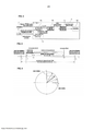
[008] A Figura 1 é um diagrama de configuração, ilustrando a configuração do dispositivo de monitoramento de pressão de pneu em uma primeira concretização.[008] Figure 1 is a configuration diagram, illustrating the configuration of the tire pressure monitoring device in a first embodiment.
[009] A Figura 2 é um diagrama de configuração de um sensor TPMS 2.[009] Figure 2 is a configuration diagram for a
[010] A Figura 3 é um diagrama de blocos de controle, ilustrando um diagrama de blocos de controle de um TMPSCU 4, para execução do controle de determinação de posição de roda.[010] Figure 3 is a control block diagram, illustrating a control block diagram of a TMPSCU 4, for the execution of the wheel position determination control.
[011] A Figura 4 é um diagrama ilustrando um processo para cálculo de uma posição rotacional de cada roda 1.[011] Figure 4 is a diagram illustrating a process for calculating a rotational position of each
[012] A Figura 5 é um diagrama ilustrando um processo para cálculo de um valor característico de dispersão.[012] Figure 5 is a diagram illustrating a process for calculating a characteristic dispersion value.
[013] A Figura 6 é um fluxograma ilustrando um fluxo do processo de controle de determina de posição de roda, na primeira concretização.[013] Figure 6 is a flow chart illustrating a flow of the wheel position determination control process, in the first embodiment.
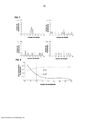
[014] A Figura 7 é um diagrama ilustrando uma relação entre as posições ro- tacionals (o número de dentes do rotor) de cada uma das rodas 1FL, 1FR, 1RL, 1RR, quando a posição rotacional do sensor TPMS 2FL da roda frontal esquerda 1FL assume o ponto mais alto, e o número de recebimento dos dados TPMS.[014] Figure 7 is a diagram illustrating a relationship between the rotational positions (the number of rotor teeth) of each of the 1FL, 1FR, 1RL, 1RR wheels, when the rotational position of the front wheel TPMS 2FL sensor left 1FL assumes the highest point, and the receiving number of the TPMS data.
[015] A Figura 8 é um diagrama ilustrando uma variação do valor característico de dispersão X, dependente do número de vezes de tempos de recepção dos dados TMPS. Descrição de sinais de referência 1 - roda 2a - sensor de pressão (mecanismo de detecção de pressão pneumática de pneu) 2b - sensor G (sensor de aceleração) 2d - transmissor 3 - receptor 4a - unidade de cálculo de posição rotacional (mecanismo de cálculo de posição rotacional) 4c - unidade de determinação de posição de roda (mecanismo de determinação de posição de roda) 4e - unidade de inibição de detecção de posição rotacional (mecanismo de inibição de detecção de posição rotacional) Concretizações para implementar a invenção[015] Figure 8 is a diagram illustrating a variation of the characteristic value of dispersion X, depending on the number of times of reception times of the TMPS data. Description of reference signals 1 -
[016] A seguir, as concretizações da presente invenção vão ser descritas com referência às concretizações com base nos desenhos. [Primeira concretização][016] In the following, the embodiments of the present invention will be described with reference to the embodiments based on the drawings. [First embodiment]
[017] A Figura 1 é um diagrama de configuração ilustrando um dispositivo de monitoramento de pneu de pneu ou pneumática de pneu, em uma primeira concreti- zação. Nesta figura, as letras terminais, anexadas a cada sinal de referência, são intencionadas para indicar o seguinte: FL significa para a roda frontal esquerda; FR significa para a roda frontal direita; RL significa para a roda traseira esquerda; e RR significa para a roda traseira direita, respectivamente. Na descrição apresentada a seguir, quando não especificamente necessário, a descrição de FL, FR, RL e RR vai ser omitida.[017] Figure 1 is a configuration diagram illustrating a tire tire or tire pneumatic monitoring device, in a first embodiment. In this figure, the terminal letters, attached to each reference signal, are intended to indicate the following: FL means for the left front wheel; FR stands for the right front wheel; RL stands for the left rear wheel; and RR stands for the right rear wheel, respectively. In the description presented below, when not specifically necessary, the description of FL, FR, RL and RR will be omitted.
[018] O dispositivo de monitoramento de pressão de pneu é, na primeira concretização, dotado com sensores TPMS (sistema de monitoramento de pressão de pneu) 2, um receptor 3, uma unidade de controle TPMS (TPMSCU) 4, um visor 5 e sensores de velocidade de roda 8. O sensor TPMS 2 é instalada em cada uma das rodas 1, e o receptor 3, a TPMSCU 4, o visor 5 e os sensores de velocidade de roda 8 são dispostos no lado do corpo do veículo.[018] The tire pressure monitoring device is, in the first embodiment, equipped with TPMS sensors (tire pressure monitoring system) 2, a
[019] O sensor TMPS 2 é instalado na posição de uma válvula pneumática (não mostrada na figura) de cada pneu. A Figura 2 é um diagrama ilustrando a configuração do sensor TPMS 2. O sensor TPMS 2 compreende um sensor de pressão (um mecanismo de detecção de pressão de pneu) 2a, um sensor de aceleração (sensor G) 2b, uma unidade de controle de sensor (CU de sensor) 2c, um transmissor 2d e uma bateria de botão 2e.[019] The TMPS 2 sensor is installed in the position of a pneumatic valve (not shown in the figure) for each tire. Figure 2 is a diagram illustrating the configuration of the
[020] Na presente invenção, o sensor de pressão 2a detecta a pressão de pneu [kPa] do pneu.[020] In the present invention, the
[021] O sensor G 2b detecta a aceleração na direção centrífuga [G] agindo no pneu.[021] The
[022] A CU de sensor 2c opera sob a energia suprida da bateria de botão 2e, e os dados TPMS, contendo as informações de pressão de pneu do pneu, detectadas pelo sensor de pressão 2a, e as ID (informações de identificação) do sensor são enviados como um sinal sem fio do transmissor 2d. Na primeira concretização, as IDs de sensor são definidas por 1 a 4.[022] The CU of
[023] A CU de sensor 2c compara a aceleração na direção centrífuga, detectada pelo sensor G 2b, com um limiar preestabelecido, para determinação de um estado de rodagem de um veículo. Quando a aceleração na direção centrífuga é inferior ao limiar de determinação de rodagem, uma determinação é feita de que o veículo está sendo parada ou está estacionado, de modo que a transmissão dos dados TMPS é interrompida. Por outro lado, quando a aceleração na direção centrífuga excede o limiar de determinação de rodagem, uma determinação é feita que o veículo está rodando, e os dados TMPS vão ser transmitidos a uma sincronização determinada.[023] CU of
[024] O receptor 3 recebe os sinais sem fio transmitidos de cada sensor TMPS 2, para decodificar e transmitir para a TPMSCU 4.[024]
[025] A TPMSCU 4 lê os respectivos dados TPMS, com base nas ID do sensor, nos dados TPMS, e com referência à relação de correspondência entre cada uma das IDs de sensor e as posições de roda armazenadas em uma memória não volátil 4d (consultar a Figura 3), a TPMSCU 4 determina em qual posição de roda os dados TPMS são correspondentes, e indica no visor 5 uma pressão pneumática de pneu contida nos dados TPMS, como a pressão pneumática da posição de roda correspondente. Quando a pressão pneumática de um pneu fica abaixo de um limiar de limite inferior, a diminuição na pressão pneumática é notificada por uma variação na cor do visor, pelo visor piscando, por um som de alarme, ou assemelhados.[025] TPMSCU 4 reads the respective TPMS data, based on the sensor IDs, the TPMS data, and with reference to the correspondence relationship between each of the sensor IDs and the wheel positions stored in a
[026] Com base na corrente de pulsos de velocidade de roda de cada um dos sensores de velocidade de roda 8, a ABSCU 6 detecta a velocidade de roda de cada roda 1, respectivamente. Quando uma certa roda tem uma tendência de travamento, um atuador ABS, não mostrado na figura, é operado, para ajustar ou manter uma pressão de cilindro de roda da roda correspondente, para eliminar a tendência de travamento. Desse modo, o controle de freio antiderrapante (ABS) é conduzido. A ABSCU 6 transmite o valor de contagem dos pulsos de velocidade de roda para a linha de comunicação CAN 7, a cada período de tempo determinado (por exemplo, 20 ms).[026] Based on the wheel speed pulse current from each of the wheel speed sensors 8, ABSCU 6 detects the wheel speed of each
[027] Cada sensor de velocidade de roda 8 é formado em um gerador de pulso, que gera uma cadeia de pulsos de velocidade de roda, produzindo um número determinado z (por exemplo, z = 48) para cada ciclo da rotação da roda 1. O sensor de velocidade de roda compreende um rotor em forma de engrenagem, girando em sincronização com a roda 1, e ambos um ímã permanente e uma bobina, disposto no lado do corpo do veículo e voltados para a periferia externa do rotor. Na medida em que o rotor gira, a superfície côncava-convexa ou corrugada do rotor atravessa o campo magnético, formado na periferia do sensor de velocidade de roda 8, de modo que a densidade do fluxo magnético varia para gerar uma força eletromotriz na bobina, e essa variação na voltagem é transmitida, como um sinal de pulso de velocidade de roda, para a ABSCU 6.[027] Each wheel speed sensor 8 is formed into a pulse generator, which generates a chain of wheel speed pulses, producing a determined number z (for example, z = 48) for each cycle of
[028] Além do controle ABS, a ABSCU 6 executa um controle de estabilização de comportamento de veículo, um controle de tração de freio e um controle LSD de freio, como um controle, para controlar a pressão de cilindro de roda da roda 1. Mais especificamente, pelo controle de estabilização de comportamento de veículo, a roda é conferida com uma força de frenagem para eliminar uma tendência de su- besterçamento do veículo, para garantir estabilidade de rodagem de veículo. Por meio do controle de tração de freio, uma força de aderência em pista de rolamento do pneu vai ser aumentada, por eliminação de uma rotação ou giro louco de uma roda motriz, quando um lado das rodas de acionamento desliza em uma pista de rolamento de baixo μ, e assemelhados. No controle LSC de freio, um diferencial é limitado por uso de um freio. A ABSCU 6 transmite um sinal de indicação de controle para a linha de comunicação CAN 7 e indica se ou não o controle de freio, descrito acima, está em execução. O indicador de controle é ajustado em "0", quando o controle de freio não está no lugar, ou executado enquanto ajustado em "1", quando executado.[028] In addition to ABS control, ABSCU 6 performs a vehicle behavior stabilization control, a brake traction control and an LSD brake control, as a control, to control the wheel cylinder pressure of
[029] Como descrito acima, com base na relação de correspondência entre as ID de sensor e a posição de roda armazenada na memória 4d, a TPMSCU 4 determina a que roda o TPMS recebido se refere. Consequentemente, quando uma rotação de pneu é conduzida enquanto o veículo está parado, a relação de correspondência, entre as ID de sensor e a posição de roda armazenada na memória 4d, não está em concordância com a relação de correspondência efetiva, e é impossível descobrir a que roda os dados TPMS se referem. Neste caso, a "rotação de pneu" se refere à operação de troca das posições de roda de instalação dos pneus, de modo a garantir um desgaste de banda de rodagem uniforme dos pneus, e, desse modo, prolongar o tempo de vida útil (o tempo de vida útil da banda de rodagem). Por exemplo, para um veículo de passeio, usualmente, as rodas de pneus frontais / traseiras são trocadas enquanto com a posição das rodas de pneus esquerdas / direitas em reverso.[029] As described above, based on the correspondence relationship between the sensor IDs and the wheel position stored in
[030] Na presente invenção, de acordo com a primeira concretização, para atualizar e armazenar a relação de correspondência entre cada ID de sensor e cada posição de roda, após uma rotação de pneu na memória 4d, quando há uma possibilidade de que uma rotação de pneu tenha sido conduzida, o período de transmissão de dados TMPS, no lado de cada sensor TPMS 2, seja alterada, e, no lado da TPMSCU 4, com base no período de transmissão dos dados TPMS e em cada pulso de velocidade de roda, uma determinação é feita com qual pneu cada sensor TPMS 2 é associado. [Modo de transmissão de posição constante][030] In the present invention, according to the first embodiment, to update and store the correspondence relationship between each sensor ID and each wheel position, after a tire rotation in the 4d memory, when there is a possibility that a rotation of tire has been driven, the period of transmission of TMPS data, on the side of each
[031] Quando o tempo de determinação de parada de veículo, antes do início de rodagem do veículo, é igual ou superior a um tempo determinado (por exemplo, 15 min), a CU de sensor 2c do sensor TPMS 2 determina que a rotação do pneu pode ter sido conduzida.[031] When the vehicle stop determination time, before the vehicle starts to run in, is equal to or greater than a determined time (for example, 15 min), the CU of
[032] Quando o tempo de determinação de parada de veículo, imediatamente antes do início de rodagem do veículo, for inferior ao tempo determinado, a CU de sensor 2c executa um "modo normal", no qual os dados TPMS são transmitidos a cada intervalo constante ou determinado (por exemplo, a um intervalo de um minuto). Por outro lado, quando o tempo de determinação de parada de veículo é igual ou superior ao tempo determinado, a CU de sensor executa um "modo de transmissão de posição constante", no qual, em um intervalo mais curto do que o intervalo de transmissão no modo normal (por exemplo, em um intervalo de cerca de 16 segun- dos), os dados TPMS são transmitidos a uma posição rotacional constante ou determinada.[032] When the vehicle stop determination time, immediately before the vehicle starts to run in, is less than the determined time, the CU of
[033] O modo de transmissão de posição constante é executado até que o número de transmissão dos dados TPMS atinja um número de vezes determinado (por exemplo, 40 giros). Quando o número de vezes da transmissão atinge o número de vezes determinado, o modo de transmissão de posição constante é transferido para o modo normal. Quando uma determinação tenha sido feita que o veículo pára antes do número de vezes de transmissão dos dados TPMS atingir o número de vezes determinado, se o tempo de determinação de parada de veículo for mais curto do que o tempo determinado (15 min), o modo de transmissão de posição constante, antes que o veículo pare, é continuado até que o número de vezes de transmissão atinja o número de vezes determinado. Quando o tempo de determinação de parada de veículo é maior do que o tempo determinado, a continuação do modo de transmissão de posição constante, antes de parada do veículo, é cancelado, e um novo modo de transmissão de posição constante é iniciado.[033] The constant position transmission mode is executed until the transmission number of the TPMS data reaches a certain number of times (for example, 40 turns). When the number of times the transmission reaches the specified number of times, the constant position transmission mode is switched to normal mode. When a determination has been made that the vehicle stops before the number of times the TPMS data is transmitted reaches the specified number of times, if the vehicle stop determination time is shorter than the determined time (15 min), the constant position transmission mode, before the vehicle stops, is continued until the number of transmission times reaches the specified number of times. When the vehicle stop determination time is longer than the determined time, the continuation of the constant position transmission mode, before the vehicle stops, is canceled, and a new constant position transmission mode is initiated.
[034] No modo de transmissão de posição constante, com base no componente da aceleração dependente de aceleração da gravidade, na direção centrífuga detectada pelo sensor G 2b, a CU de sensor 2c determina uma sincronização de transmissão dos dados TPMS no modo de transmissão de posição constante. A aceleração na direção centrífuga, agindo no sensor TPMS 2, varia de acordo com a aceleração / desaceleração das rodas 1, ainda que o componente dependente de aceleração da gravidade fique sempre constante. Isto é, a aceleração na direção centrífuga, agindo no sensor TPMS, mostra uma forma de onda com +1 [G] em um ponto de topo, -1 [G] em um ponto de fundo, e 0 [G] na posição intermediária de 90°, entre o ponto de topo e o ponto de fundo. Em outras palavras, por monitoramento da grandeza e da direção do componente da aceleração de aceleração da gravidade na direção centrífuga, é possível entender ou identificar a posição rotacional do sensor TPMS 2. Por conseguinte, por exemplo, por transmissão de dados TPMS a um pico do componente dependente de aceleração da gravidade, os dados TPMS podem ser transmitidos constantemente no ponto de topo. [Modo de autoaprendizagem][034] In constant position transmission mode, based on the gravity acceleration-dependent acceleration component, in the centrifugal direction detected by the
[035] Quando o tempo tiver passado de um predeterminado (por exemplo, 15 min) ou mais da posição desligada (OFF) para a posição ligada (ON) da chave de ignição, a TPMSCU 4 determina que a rotação do pneu pode ter sido conduzida.[035] When the time has passed from a predetermined (for example, 15 min) or more from the OFF position to the ON position of the ignition key, TPMSCU 4 determines that the tire rotation may have been conducted.
[036] Quando o tempo decorrido de OFF para ON da chave de ignição for mais curto do que o tempo predeterminado, com base nas informações de pressão de pneu no TPMS, transmitidas de cada sensor TPMS 2, a TPMSCU 4 executa um "modo de monitoramento", no qual a pressão pneumática do pneu de cada roda 1 é monitorada. Por outro lado, quando o tempo decorrido de OFF para ON da chave de ignição for maior do que o tempo predeterminado, a TPMSCU 4 executa um "modo de autoaprendizagem", que vai ser conduzido até que as posições das rodas de todos os sensores TPMS 2 sejam determinadas, ou até que um tempo de deslocamento cumulativo, predeterminado (por exemplo, 8 minutos), a partir do início deste modo, tenha passado. Quando as posições das rodas de todos os sensores TPMS forem determinadas, ou o tempo cumulativo predeterminado tiver passado, o controle é transferido para o modo de monitoramento.[036] When the elapsed time from OFF to ON of the ignition key is shorter than the predetermined time, based on the tire pressure information in the TPMS, transmitted from each
[037] Mesmo no modo de autoaprendizagem, é ainda possível monitorar a pressão pneumática dos pneus das informações de pressão pneumática contidas nos dados TPMS. Consequentemente, a exibição da pressão pneumática e o aviso de uma menor pressão pneumática são conduzidos com base na relação de correspondência entre as ID de sensor e a posição das rodas atualmente armazenadas na memória 4d, durante o modo de rodagem automático.[037] Even in the self-learning mode, it is still possible to monitor the pneumatic tire pressure from the pneumatic pressure information contained in the TPMS data. Consequently, the display of the pneumatic pressure and the warning of a lower pneumatic pressure are conducted based on the corresponding relationship between the sensor IDs and the position of the wheels currently stored in
[038] No modo de autoaprendizagem, a TPMSCU 4 recebe um valor de contagem dos pulsos de velocidades de rodas da unidade de controle ABS (ABSCU) 6 pela linha de comunicação CAN 7, e executa o controle de determinação de posição de roda descrito abaixo. [Controle de determinação de posição de roda][038] In self-learning mode, the TPMSCU 4 receives a wheel speed pulse count value from the ABS control unit (ABSCU) 6 via the
[039] A Figura 3 é um diagrama de blocos de controle da TPMSCU 4, para execução do controle de determinação de posição de roda. A TPMSCU 4 tem uma unidade de cálculo de posição rotacional (o mecanismo de detecção de posição ro- tacional) 4a, uma seção de cálculo de dispersão 4b, uma seção de determinação de posição de roda (o mecanismo de determinação de posição de roda) 4c, uma memória 4d, uma unidade de inibição de detecção (mecanismo de inibição de detecção) de posição rotacional 4e.[039] Figure 3 is a control block diagram of the TPMSCU 4, for carrying out the wheel position determination control. TPMSCU 4 has a rotational position calculation unit (the rotational position detection mechanism) 4a, a
[040] A unidade de cálculo de posição rotacional 4a recebe os dados TPMS, após serem decodificados para serem transmitidos do receptor 3, e os valores de contagem dos pulsos de velocidade de roda transmitidos da ABSCU 6 para a linha de comunicação CAN 7, para calcular uma posição rotacional (número de dentes de rotor) para cada rotor, quando a posição rotacional de cada sensor TPMS assume o ponto de topo. Notar que o "número de dentes" indica que dente o sensor de velocidade de roda 8 está contando, e pode ser obtido por divisão do valor de contagem dos pulsos de velocidade de roda por um valor de contagem por rotação do pneu (isto é, o número de dentes por rotação z = 48). Na primeira concretização, quando o valor de contagem dos pulsos de velocidade de roda do primeiro tempo, a partir do modo de autoaprendizagem ser introduzido, o valor obtido por adição de 1 ao restante da operação de divisão do valor de contagem pelo número de dentes de 1 ciclo ou rotação é adotado como o valor de referência de dentes. No segundo e nos tempos subsequentes, com base no número de contagem dos pulsos de velocidade de roda com relação ao número de referência de dentes (isto é, o valor de contagem de momento - o valor de contagem no primeiro tempo), o número ou os dentes podem ser determinados.[040] The rotational
[041] A Figura 4 é um diagrama mostrando um processo para calcular a posição rotacional de cada roda 1.[041] Figure 4 is a diagram showing a process for calculating the rotational position of each
[042] Na Figura 4, t1 representa o tempo quando o valor de contagem dos pulsos de velocidade de roda é introduzido, t2 representa o tempo quando a posição rotacional do sensor TPMS 2 atinge o ponto de topo, t3 representa o tempo quando a recepção dos dados TPMS pela TPMSCU 4 é completada, e t5 representa o tem po quando o valor de contagem dos pulsos de velocidade de roda é introduzido. Neste caso, t1, t4 e t5 podem ser medidos de fato, t3 pode ser calculado por subtração da extensão de dados (valor nominal, por exemplo, cerca de 10 ms) dos dados TPMS de t4, e t2 pode ser calculado por subtração de um retardo de tempo na transmissão (t2 pode ser determinado de antemão por experimento ou assemelhados) de t3.[042] In Figure 4, t1 represents the time when the wheel speed pulse count value is entered, t2 represents the time when the rotational position of the
[043] Consequentemente, supor que o número de dentes em t1 é zt1, o número de dentes em t2 é zt2, e o número de dentes em t5 é zt5, respectivamente, a equação a seguir é estabelecida: (t2-t1)/(t5-t1)=(zt2-zt1)/(zt5-zt1) Em virtude de que zt2=zt1+(zt5-zt1)*(t2-t1)/(t5-t1)[043] Consequently, suppose that the number of teeth in t1 is zt1, the number of teeth in t2 is zt2, and the number of teeth in t5 is zt5, respectively, the following equation is established: (t2-t1) / (t5-t1) = (zt2-zt1) / (zt5-zt1) Because zt2 = zt1 + (zt5-zt1) * (t2-t1) / (t5-t1)
[044] o número de dentes zt2 é expresso na maneira apresentada a seguir, quando a PAM do sensor TPMS 2 é no ponto de topo: zt2=zt1+ (zt5-zt1)*(t2-t1)/(t5-t1)[044] the number of teeth zt2 is expressed as follows, when the PAM of the
[045] A seção de computação de dispersão 4b acumula uma posição rotacio- nal de cada roda 1, que é calculada na unidade de cálculo de posição rotacional 4a para cada ID de sensor, para obter dados de posição rotacional, e calcula um grau de dispersão em cada dados de posição rotacional, para cada ID de sensor, como um valor característico de dispersão. O cálculo do valor característico de dispersão é feito cada vez que a posição rotacional para ID de sensor idêntica é calculada pela unidade de cálculo de posição rotacional 4a.[045]
[046] A Figura 5 é um diagrama ilustrando um processo para calcular o valor característico de dispersão. De acordo com a primeira concretização, um círculo unitário (um círculo com raio de 1), com a origem (0, 0) no plano bidimensional, é assumido, e a posição rotacional θ [°] (= 360 x (o número de dentes do rotor / 48)) de cada roda 1 é convertida nas coordenadas circunferenciais (cos θ, sen θ) no círculo unitário. Mais especificamente, a posição rotacional de cada roda 1 é calculada como se segue: considerar um vetor tendo a origem (0, 0) como o ponto de partida e as coordenadas (cos θ, sen θ) com a extremidade com uma extensão de 1, os vetores médios (ave_cos θ, ave_sin θ) de cada vetor dos mesmos dados de posição ro- tacional são obtidos, e a quantidade escalar do vetor médio é calculada como o valor característico de dispersão X dos dados de posição rotacional: cos θ, sin θ)=(cos((zt2+1)*2π/48), sin((zt2+1)*2π/48))[046] Figure 5 is a diagram illustrating a process for calculating the characteristic dispersion value. According to the first embodiment, a unitary circle (a circle with radius of 1), with the origin (0, 0) in the two-dimensional plane, is assumed, and the rotational position θ [°] (= 360 x (the number of rotor teeth / 48)) of each
[047] Consequentemente, supor que o número de vezes de recepção dos dados TPMS com relação à ID de sensor idêntica como n (n é um número inteiro positivo), os vetores médios (ave_cos θ, ave_sin θ) são expressos a seguir: (ave_cos θ, ave_sin θ)=((∑(cos θ))/n, (∑(sin θ))/n)[047] Consequently, suppose that the number of times the TPMS data is received with respect to the identical sensor ID as n (n is a positive integer), the mean vectors (ave_cos θ, ave_sin θ) are expressed below: ( ave_cos θ, ave_sin θ) = ((∑ (cos θ)) / n, (∑ (sin θ)) / n)
[048] O valor característico de dispersão X pode ser, desse modo, representado do seguinte modo: X=ave_cos θ2+ave_sin θ2[048] The characteristic dispersion value X can therefore be represented as follows: X = ave_cos θ2 + ave_sin θ2
[049] A unidade de determinação de posição de roda 4c funciona da seguinte maneira. Os valores característicos de dispersão X de cada um dos dados de posição rotacional de mesma e idêntica ID de sensor, calculada pela unidade de cálculo de dispersão 4b são comparados. Quando o maior valor dos valores característicos de dispersão X é maior do que um primeiro limiar (por exemplo, 0,57) e os restantes 3 valores característicos de dispersão X são todos inferiores a um segundo limiar (por exemplo, 0,37), uma determinação é feita de que a posição de roda dos dados de posição rotacional, correspondentes ao valor característico de dispersão X com o maior valor, isto é, a posição de roda do sensor de velocidade de roda 8 que tenha detectado os dados de posição rotacional correspondentes, é a posição de roda do sensor TPMS 2 correspondente à ID de sensor dos dados de posição rotacional. Esta determinação é conduzida para todas as IDs de sensor; a relação de correspondência entre cada ID de sensor e cada posição de roda é obtida como sendo registrada na memória 4d, no processo de atualização.[049] The wheel
[050] A unidade de inibição de detecção de posição rotacional 4e inibe ou impede a unidade de cálculo de posição rotacional 4a de calcular a posição rotacio- nal de cada roda 1, quando qualquer roda 1 está sob um controle de freio, no qual uma pressão de cilindro de roda é controlada (para um controle de freio antibloqueio, um controle de estabilidade de comportamento de veículo, um controle de tração de freio e um controle LSD de freio) pela ABSCU 6. A determinação de se o controle de freio está no lugar ou em andamento pode ser feita com base em um valor da indicação de controle, que é introduzida pela linha de comunicação CAN 7; [Processo de controle de determinação de posição de roda][050] The rotational position
[051] A Figura 6 é um fluxograma ilustrando o fluxo do processo de controle de determinação de posição de roda, de acordo com a primeira concretização. A seguir, as respectivas etapas de operação vão ser descritas. Na descrição apresentada a seguir, o caso da ID de sensor sendo "1" é considerado. No entanto, para as outras IDs (ID = 2, 3, 4), o processo de controle de determinação de posição de roda é também conduzido em paralelo.[051] Figure 6 is a flow chart illustrating the flow of the wheel position determination control process, according to the first embodiment. In the following, the respective operating steps will be described. In the description presented below, the case of the sensor ID being "1" is considered. However, for the other IDs (ID = 2, 3, 4), the wheel position determination control process is also conducted in parallel.
[052] Na etapa S1, a unidade de cálculo de posição rotacional 4a recebe os dados TPMS com a ID de sensor sendo 1.[052] In step S1, the rotational
[053] Na etapa S2, a unidade de inibição de detecção de posição rotacional 4e determina se ou não um controle de freio está em andamento, e, se SIM, o controle retorna para a etapa S1, se NÃO, o controle continua para a etapa S3.[053] In step S2, the rotational position
[054] Na etapa S3, a seção de cálculo de posição rotacional 4a calcula a posição rotacional de cada roda 1.[054] In step S3, the rotational
[055] Na etapa S4, a unidade de cálculo de dispersão 4b calcula os valores característicos de dispersão X dos dados de posição rotacional de cada roda 1.[055] In step S4, the
[056] Na etapa S6, uma determinação é feita de se os dados TPMS, com a ID de sensor sendo igual a 1, são recebidos por um número determinado de vezes (por exemplo, 10 vezes) ou mais. Se o resultado de determinação for SIM, a operação vai para a etapa S6. Se a determinação for NÃO, a operação retorna para a etapa S1.[056] In step S6, a determination is made as to whether the TPMS data, with the sensor ID being equal to 1, is received a specified number of times (for example, 10 times) or more. If the determination result is YES, the operation goes to step S6. If the determination is NO, the operation returns to step S1.
[057] Na etapa S6, a seção de determinação de posição de roda 4c determina se o valor maior do valor característico de dispersão é superior ao primeiro limiar de 0,57, e se o valor dos valores característicos de dispersão remanescentes são inferiores ao segundo limiar de 0,37. Se a determinação for SIM, a operação vai para a etapa S7; se o resultado de determinação for NÃO, a operação vai para a etapa S8.[057] In step S6, the wheel
[058] Na etapa S7, a seção de determinação de posição de roda 4c determina a posição de roda de dados de posição rotacional correspondentes ao mais alto canal de retenção de placa defletora como a posição de roda da ID de sensor. Depois, o modo de autoaprendizagem termina.[058] In step S7, the wheel
[059] Na etapa S8, a seção de determinação de posição de roda 4c determina se um tempo de funcionamento acumulado ou cumulativo predeterminado (por exemplo, 8 min) passou a partir do início do modo de autoaprendizagem. Se o resultado da determinação for SIM, o modo de autoaprendizagem é terminado. Se o resultado da determinação for NÃO, a operação retorna para a etapa S1.[059] In step S8, the wheel
[060] Quando a seção de determinação de posição de roda 4c pode determinar as posições de roda para todas as IDs de sensor dentro do tempo de deslocamento acumulado determinado, a relação de correspondência entre a ID de sensor e a posição de roda é atualizada e armazenada na memória 4d para registro. Por outro lado, quanto for impossível determinar a posição de roda para todas as IDs de sensor dentro do tempo de deslocamento acumulado determinado, a relação de correspondência entre as IDs de sensor e cada posição de roda, armazenada no momento na memória 4d, é continuada a ser usada.[060] When the wheel
[061] A seguir, a operação vai ser explicada. [Operação da determinação de posição de roda pelo grau de dispersão nos dados de posição rotacional][061] Next, the operation will be explained. [Operation of the determination of wheel position by the degree of dispersion in the rotational position data]
[062] O sensor TPMS 2 funciona da seguinte maneira: quando o tempo de determinação de parada de veículo, imediatamente antes do início de rodagem de veículo, for igual ou superior a 15 min, uma determinação é feita de que há uma possibilidade de a rotação de pneu tenha sido conduzida, e a operação vai do modo normal para o modo de transmissão de posição constante. No modo de transmissão de posição constante, após terem sido passados 16 segundos do tempo de trans- missão da vez anterior e a posição rotacional do próprio sensor TPMS atingir o ponto de topo, cada sensor TPMS 2 transmite os dados TPMS.[062] The
[063] Por outro lado, quando o tempo decorrido entre OFF e ON da chave de ignição for de 15 min, ou maior, a TPMSCU 4 vai do modo de monitoramento para o modo de autoaprendizagem. No modo de autoaprendizagem, cada vez que os dados TPMS são recebidos de cada sensor TPMS 2, a TPMSCU 4 calcula a posição rotacional (o número de dentes do rotor) de cada roda 1, quando a posição rotacio- nal do sensor TPMS 2 atinge o ponto de topo, com base nos tempo de introdução do valor de contagem dos pulsos de velocidade de roda, tempo de completamento de recepção dos dados TPMS e assemelhados. Este é conduzido repetidamente por 10 ou mais vezes e acumulado como os dadas de posição rotacional. Entre os dados de posição rotacional, a posição de roda na qual os dados de posição rotacional, com o menor grau de dispersão, são determinados como a posição de roda daquele sensor TPMS 2.[063] On the other hand, when the time between OFF and ON of the ignition key is 15 min, or longer, TPMSCU 4 goes from the monitoring mode to the self-learning mode. In self-learning mode, each time TPMS data is received from each
[064] Quando o veículo se desloca ou roda, as velocidades de rotação de cada roda 1 podem ser diferentes entre si, devido à diferença nas trilhas entre as rodas interna e externa, à trava e ao deslizamento das rodas 1 e à diferença na pressão pneumática dos pneus. Mesmo quando o veículo roda reto, como o motorista pode ainda fazer correções mínimas na roda de esterçamento, e há uma certa diferença na superfície de rolamento entre os lados direito e esquerdo, a diferença na rotação ainda se desenvolve entre as rodas frontal e traseira 1FL e 1FR, e entre as rodas esquerda e direita 1RL e 1RR. Isto é, ainda que haja uma diferença em velocidade de rotação de cada roda, de acordo com o estado de rolamento do veículo, uma vez que o sensor TPMS 2 e o sensor de velocidade de roda 8 (os dentes do seu rotor) giram integralmente, para o período de saída de um sensor TPMS 2 específico, o período de saída do sensor de velocidade de roda 8, associado com a mesma roda, é mantido sendo sincronizado (em associação), independentemente da distância de deslocamento e do estado de rodagem.[064] When the vehicle is traveling or rotating, the rotation speeds of each
[065] Consequentemente, por observação do grau de dispersão nos dados de posição rotacional de cada roda 1, com relação a um período de transmissão dos dados TPMS, é possível fazer uma determinação altamente precisa nas posições de roda de cada sensor TPMS 2.[065] Consequently, by observing the degree of dispersion in the rotational position data of each
[066] A Figura 7 ilustra a relação entre as posições rotacionals (o número de dentes dos rotores) das rodas 1FL, 1FR, 1RL e 1RR, quando a posição rotacional do sensor TPMS 2 2FL da roda frontal esquerda 1FL atinge o ponto de topo e o número de vezes de recepção dos dados TPMS. Neste caso, (a) corresponde ao sensor de velocidade de roda 8FL da roda frontal esquerda 1FL, (b) corresponde ao sensor de velocidade de roda 8FR da roda frontal direita 1FR, (c) corresponde ao sensor de velocidade de roda 8RL da roda traseira esquerda 1RL, e (d) corresponde ao sensor de velocidade de roda 8RR da roda traseira direita 1RR.[066] Figure 7 illustrates the relationship between the rotational positions (the number of rotor teeth) of the 1FL, 1FR, 1RL and 1RR wheels, when the rotational position of the
[067] Como vai ser evidente da Figura 7, enquanto que os graus de dispersão são altos com relação às posições de roda (o número de dentes), obtidas dos sensores de velocidade de roda 8FR, 8RL e 8RR, com relação às outras rodas (a roda frontal direita 1FR, a roda traseira esquerda 1RL e a roda traseira direita 1RR), o grau de dispersão da posição de roda, obtido do sensor de velocidade de roda 8FL com relação à própria roda (a roda frontal esquerda 1FL), é o menor ou mínimo, de modo que o período de saída do sensor TPMS 2 2FL e o período de saída do sensor de velocidade de roda 8FL são quase que sincronizados entre si.[067] As will be evident from Figure 7, while the degrees of dispersion are high with respect to the wheel positions (the number of teeth), obtained from the wheel speed sensors 8FR, 8RL and 8RR, with respect to the other wheels (the right front wheel 1FR, the left rear wheel 1RL and the right rear wheel 1RR), the degree of dispersion of the wheel position, obtained from the wheel speed sensor 8FL with respect to the wheel itself (the left front wheel 1FL), is the smallest or minimum, so the output period of the
[068] Como um dos aparelhos de pressão pneumática de pneu convencionais, um sensor de inclinação é disposto para cada sensor TPMS, e a relação entre a posição de roda do sensor TPMS e o ângulo de inclinação é usada para determinar a posição de roda do sensor TPMS. Para este tipo de aparelho de monitoramento de pressão pneumática de pneu, correspondente à rodagem do veículo, a diferença na velocidade de rotação ocorre entre as 4 rodas, de modo que a correspondência entre a posição de roda do sensor TPMS e o ângulo de inclinação varia. Por conseguinte, é impossível fazer uma determinação altamente precisa na posição de roda de cada sensor TPMS.[068] As one of the conventional pneumatic tire pressure devices, an inclination sensor is arranged for each TPMS sensor, and the relationship between the wheel position of the TPMS sensor and the angle of inclination is used to determine the wheel position of the TPMS sensor. For this type of pneumatic tire pressure monitoring device, corresponding to the vehicle's running-in, the difference in rotation speed occurs between the 4 wheels, so that the correspondence between the wheel position of the TPMS sensor and the angle of inclination varies . It is therefore impossible to make a highly accurate determination of the wheel position of each TPMS sensor.
[069] Como um outro aparelho de monitoramento de pressão pneumática de pneu convencional, o mesmo número de receptores, como aqueles dos sensores TPMS, são dispostos vizinhos aos sensores, respectivamente; com base na intensidade da onda eletromagnética dos sinais sem fio recebidos, a posição de roda de cada sensor TPMS é determinada. Neste caso, é necessário considerar a saída do sensor, a dispersão de sensibilidade do receptor e o efeito da antena em harpa para a disposição dos receptores, e o meio físico e a disposição de recepção determinam o desempenho. Além disso, 4 receptores devem ser dispostos. Consequentemente, o custo é mais alto.[069] Like another conventional tire pneumatic pressure monitoring device, the same number of receivers, as those of the TPMS sensors, are arranged next to the sensors, respectively; based on the intensity of the electromagnetic wave of the received wireless signals, the wheel position of each TPMS sensor is determined. In this case, it is necessary to consider the sensor output, the dispersion of sensitivity of the receiver and the effect of the antenna in harp for the disposition of the receivers, and the physical environment and the disposition of reception determine the performance. In addition, 4 receivers must be arranged. Consequently, the cost is higher.
[070] Por outro lado, para o dispositivo de monitoramento de pressão pneumática de pneu na primeira concretização, a posição de roda de cada sensor TPMS 2 pode ser especificada sem uso da intensidade de onda eletromagnética, de modo que seja possível determinar a posição de roda de cada sensor TPMS 2, independentemente do meio físico e disposição de recepção. Além disso, um receptor 3 é suficiente, o que vai provocar a eliminação do custo para sensores adicionais.[070] On the other hand, for the pneumatic tire pressure monitoring device in the first embodiment, the wheel position of each
[071] Além disso, de acordo com a primeira concretização, a TPMSCU 4 calcula e determina que a posição rotacional de cada roda 1 é posicionada no ponto de topo, com base no componente dependente de aceleração da gravidade de uma aceleração na direção centrífuga, que é detectável do sensor G 2b. Uma vez que o sensor G 2b é usado no dispositivo de monitoramento de pressão pneumática de pneu existente, para detecção de parada e deslocamento de veículo, o sensor TPMS existente pode ser usado comumente de modo que não haja qualquer necessidade para adicionar novos sensores no lado do veículo. O custo pode ser, desse modo, reduzido. [Operação na determinação do grau de dispersão do valor característico de dispersão][071] In addition, according to the first embodiment, TPMSCU 4 calculates and determines that the rotational position of each
[072] Em virtude da posição rotacional da roda 1 ser indicada pelos dados angulares com periodicidade, o grau de dispersão da posição rotacional não pode ser determinado por uso da fórmula de dispersão geral definida pela média do "quadrado da diferença do valor médio ou média".[072] Because the rotational position of
[073] Desse modo, na primeira concretização, a unidade de cálculo de dispersão 4b funciona da seguinte maneira. A posição rotacional θ de cada roda 1, obtida de cada sensor de velocidade de roda 8, é convertida nas coordenadas circunfe- renciais (cos θ, sen θ) de um círculo unitário tendo a origem (0, 0) no centro. As coordenadas (cos θ, sen θ) são consideradas como vetores, os vetores médios (ave_cos θ, ave_sin θ) dos vetores dos mesmos dados de posição rotacional são obtidos, e a quantidade escalar do vetor médio é calculada como o valor característico de dispersão X. Por conseguinte, é possível evitar a periodicidade na determinação do grau de dispersão da posição rotacional.[073] Thus, in the first embodiment, the
[074] A Figura 8 mostra um diagrama ilustrando uma variação no valor característico de dispersão X, de acordo com o número de recebimento dos dados TPMS. Na Figura 8, a própria roda apresenta o valor característico de dispersão X, calculado nos dados de posição rotacional do sensor de velocidade de roda 8, na mesma roda na qual o sensor TPMS é instalado, enquanto que as outras rodas mostram o valor característico de dispersão X, calculado nos dados de posição rotacional do sensor de velocidade de rota 8, na roda diferente daquelas nas quais são instalados os sensores TPMS.[074] Figure 8 shows a diagram illustrating a variation in the characteristic dispersion value X, according to the number of receipt of the TPMS data. In Figure 8, the wheel itself presents the characteristic dispersion value X, calculated in the rotational position data of the wheel speed sensor 8, on the same wheel on which the TPMS sensor is installed, while the other wheels show the characteristic value of dispersion X, calculated in the rotational position data of the route speed sensor 8, in a different wheel from those in which the TPMS sensors are installed.
[075] Como mostrado na Figura 8, na medida em que o número de recepções de dados TPMS na mesma ID de sensor aumenta, esta tendência é indicada quando a característica de dispersão X se aproxima de "1", enquanto que o valor característico de dispersão X para a outra roda se aproxima de "0". Desse modo, pode ser ideal selecionar o valor máximo (isto é, o valor característico de dispersão mais próximo de "1") no atingimento de um número suficiente de recepções (cerca de várias dezenas de vezes). No entanto, uma vez que é impossível informar ao motorista com informações precisas do estado dos pneus, durante o período de deter-minação de posição roda, imediatamente após uma rotação do pneu, o retardo no tempo de determinação não vai ser preferível. Por outro lado, no número insuficiente de recepções (tal como várias vezes), nenhuma diferença no valor característico de dispersão, com relação à própria e às outras rodas, é detectável e a diminuição na precisão de detecção vai ser antecipada.[075] As shown in Figure 8, as the number of TPMS data receipts in the same sensor ID increases, this trend is indicated when the dispersion characteristic X approaches "1", while the characteristic value of dispersion X for the other wheel approaches "0". In this way, it may be ideal to select the maximum value (that is, the characteristic dispersion value closest to "1") on reaching a sufficient number of receptions (about several dozen times). However, since it is impossible to inform the driver with accurate information on the condition of the tires, during the period of determining the wheel position, immediately after a tire rotation, the delay in the determination time will not be preferable. On the other hand, in the insufficient number of receptions (such as several times), no difference in the characteristic dispersion value, with respect to itself and to the other wheels, is detectable and the decrease in the detection accuracy will be anticipated.
[076] Desse modo, na primeira concretização, a unidade de determinação de posição de roda 4c compara os valores característicos de dispersão em cada um dos dados de posição rotacional, com relação a uma ID de sensor específica, no recebimento dos dados TPMS com relação àquele sensor específico dez vezes ou mais, e detecta que o valor máximo dos valores característicos de dispersão X excede um primeiro valor de limiar 0,57, enquanto os três valores característicos de dispersão remanescentes ficam abaixo de um segundo valor de limiar 0,37, depois, a posição de roda dos dados de posição rotacional, correspondente ao valor caracte-rístico de dispersão máximo V, vai ser identificada como a posição de roda dessa ID de sensor.[076] Thus, in the first embodiment, the wheel
[077] Não apenas por seleção do valor máximo dos valores característicos de dispersão, por comparação com o primeiro valor de limiar (0,57), um certo grau de precisão de determinação pode ser garantido. Além disso, por comparação de valores característicos de dispersão, diferentes do valor máximo, com o segundo valor de limiar (0,37), uma diferença predeterminada (de 0,2 ou mais) pode ser confirmada, o que melhor ainda mais a precisão de determinação. Portanto, a um número relativamente pequeno de recebimentos, tal como dez vezes, ambas a precisão de determinação e a diminuição do tempo de determinação podem ser obtidas. [Operação de transmissão intermitente de dados TPMS][077] Not only by selecting the maximum value of the characteristic dispersion values, by comparison with the first threshold value (0.57), a certain degree of determination accuracy can be guaranteed. In addition, by comparing characteristic dispersion values, different from the maximum value, with the second threshold value (0.37), a predetermined difference (of 0.2 or more) can be confirmed, which further improves the accuracy of determination. Therefore, with a relatively small number of receipts, such as ten times, both the determination accuracy and the decrease in the determination time can be obtained. [Operation of intermittent transmission of TPMS data]
[078] Cada sensor TPMS 2 transmite dados TPMS após passagem de 16 segundos do tempo de transmissão prévio de dados TPMS, e na sincronização na qual a própria posição rotacional atinge o ponto de topo. Na primeira concretização, uma vez que os valores característicos de dispersão X de cada um dos dados de posição rotacional são comparados entre si, para determinação da posição de roda, com relação ao sensor TPMS 2, que tenha transmitido os dados TPMS, um certa quantidade de distância de deslocamento cumulativa vai ser necessária para provocar uma diferença nos valores característicos de dispersão X, entre a própria roda (a mesma roda) e a outra roda (outra roda de veículo).[078] Each
[079] Considerando que os dados TPMS vão ser transmitidos cada vez que a posição rotacional dos dados TPMS atinge um ponto de topo, nenhuma diferença substancial no valor característico de dispersão vai ser esperada entre a própria roda e outra, de modo que pode ser difícil fazer uma determinação de posição de roda.[079] Considering that the TPMS data will be transmitted each time the rotational position of the TPMS data reaches a top point, no substantial difference in the characteristic dispersion value will be expected between the wheel itself and another, so it can be difficult make a determination of wheel position.
[080] Desse modo, por ajuste de um intervalo de transmissão a 16 segundos + α, uma certa quantidade de distância de deslocamento cumulativa vai ser obtida, até que os dados TPMS sejam recebidos dez vezes ou mais. Portanto, uma diferença suficiente no valor característico de dispersão X, entre a própria roda e outra, pode ser criada para garantir uma determinação precisa da posição de roda. [Operação de eliminação de consumo de energia][080] Thus, by adjusting a transmission interval to 16 seconds + α, a certain amount of cumulative travel distance will be obtained, until the TPMS data is received ten times or more. Therefore, a sufficient difference in the characteristic dispersion value X, between the wheel itself and another, can be created to ensure an accurate determination of the wheel position. [Operation to eliminate energy consumption]
[081] Por transmissão de dados TPMS quarenta (40) vezes durante o modo de transmissão de posição constante, o sensor TPMS 2 transfere para o modo normal. O sensor TPMS 2 consome a energia da bateria de botão 2e, na transmissão dos dados TPMS, de modo que o tempo de vida útil de bateria da bateria de botão 2e vai ser mais curto na medida em que o modo de transmissão de posição constante continua. Desse modo, quando cada posição de roda pode não ser determinada, a despeito da passagem de tempo de deslocamento cumulativo suficiente, o modo de transmissão de posição constante vai ser terminado, para transferir para o modo normal, o que pode eliminar a diminuição do tempo de vida útil da bateria.[081] By transmitting TPMS data forty (40) times during the constant position transmission mode, the
[082] Por outro lado, quando a TPMSCU 4 não pode determina a correspondência entre cada ID de sensor e cada posição de roda, a despeito do tempo decorrido de deslocamento cumulativo de oito (8) minutos, o modo de autoaprendizagem vai ser terminado e o processo passa para o modo de monitoramento. O número total de dados TPMS é trinta (30) vezes ou menos, quando o tempo de deslocamento cumulativo tiver passado de oito minutos, o modo de autoaprendizagem vai ser substancialmente terminado em sincronização com o completamento do modo de transmissão de posição constante do sensor TPMS 2. [Operação de eliminação de retardo de determinação de posição de roda][082] On the other hand, when TPMSCU 4 cannot determine the correspondence between each sensor ID and each wheel position, regardless of the elapsed time of cumulative eight (8) minute travel, the self-learning mode will be terminated and the process goes into monitoring mode. The total number of TPMS data is thirty (30) times or less, when the cumulative travel time has passed eight minutes, the self-learning mode will be substantially ended in synchronization with the completion of the constant position transmission mode of the TPMS sensor. 2. [Delay operation for determining the position of the wheel]
[083] A CU de sensor 2c do sensor TPMS 2 detecta a posição rotacional do sensor TPMS 2, com base no componente dependente de aceleração da gravidade da aceleração centrífuga detectada pelo sensor G 2b, durante o modo de transmissão de posição constante, e transmite os dados TPMS no pico do componente dependente de aceleração da gravidade, de modo que os dados TPMS sejam transmitidos no ponto de topo durante a transmissão. Embora a aceleração centrífuga exercida no sensor TPMS 2 possa ser submetida a uma variação, devido à aceleração / desaceleração da roda 1, o componente dependente de aceleração da gravidade estabelece uma forma de onda de largura constante (-1 a 1 [G]) e varia em um período extremamente mais curto, comparado com a velocidade de variação na aceleração centrífuga, acompanhada pela aceleração / desaceleração do veículo. Portanto, é fácil impor a variação no componente dependente de aceleração da gravidade com base nas acelerações centrífugas.[083] The
[084] No entanto, quando um controle de freio, tal como um controle ABS e um controle de tração de freio, está sendo executado, a roda 1, sob controle, é submetida a vibrar longitudinalmente em um período extremamente curto, devido a esse controle, a aceleração centrífuga detectada pelo sensor G 2b vai ser afetada e flutua em um período extremamente curto, com uma grande largura ou amplitude (várias dezenas de [G] ou mais). Desse modo, a CU de sensor 2c pode determinar erroneamente o tremor ou as flutuações como o pico no componente dependente de aceleração da gravidade, de modo que a probabilidade existe que os dados TPMS sejam transmitidos a uma posição rotacional diferente do pico.[084] However, when a brake control, such as an ABS control and a brake traction control, is being performed,
[085] Desse modo, a unidade de cálculo de posição rotacional 4a da TPMSCU 4 calcula a posição rotacional de cada roda 1, na sincronização na qual a posição rotacional de cada sensor TPMS 2 tenha atingido o seu pico, com base na sincronização de recebimento dos dados TPMS e do valor de contagem de pulsos de velocidade de roda para cada roda, nesta sincronização. Portanto, a unidade de cálculo de posição rotacional 4a calcula a posição rotacional de cada roda 1, que tenha sido transmitida na posição rotacional diferente do ponto de topo, como aquela transmitida no ponto de topo, e a unidade de cálculo de dispersão 4b é para calcular o valor característico de dispersão X para cada roda 1, por inclusão desta posição rotacional nos dados de posição rotacional. Consequentemente, devido à inclusão de dados falsos de posição rotacional nos dados de posição rotacional para cada roda, a criação da diferença entre o valor máximo e os outros valores, para cada valor característico de dispersão X, vai ser retardada e a determinação de posição de roda vai ser retardada.[085] Thus, the rotational
[086] Em comparação, na primeira concretização, a unidade de inibição de detecção de posição rotacional 4e inibe a unidade de cálculo de posição rotacional 4a de detectar a posição rotacional para cada roda, quando um controle de freio, tal como um controle ABS, está sendo executado.[086] In comparison, in the first embodiment, the rotational position
[087] Mais especificamente, quando há a probabilidade de que a sincronização de transmissão dos dados TPMS é diferente da sincronização de transmissão normal ou comum, por inibição do cálculo da posição rotacional de cada roda, com base nos dados TPMS, o cálculo do valor característico de dispersão X, usando dados errôneos ou falsos, vai ser eliminado.[087] More specifically, when there is a probability that the transmission synchronization of the TPMS data is different from the normal or common transmission synchronization, by inhibiting the calculation of the rotational position of each wheel, based on the TPMS data, the calculation of the value dispersion characteristic X, using erroneous or false data, will be eliminated.
[088] Exposto de outro modo, quando há uma probabilidade de que a sincronização de transmissão dos dados TPMS ter sido feita em uma sincronização diferente da sincronização normal ou comum, então, por inibição do cálculo da posição rotacional de cada roda 1, os dados errôneos de posição rotacional vão ser impedidos de serem incluídos nos dados de posição rotacional para cada roda. Portanto, um retardo na determinação da posição de roda vai ser eliminado, e a relação de correspondência entre cada ID de sensor e cada posição de roda pode ser determinado prematuramente.[088] Exposed in another way, when there is a probability that the transmission synchronization of the TPMS data has been made in a different synchronization than the normal or common synchronization, then, by inhibiting the calculation of the rotational position of each
[089] Vai ser feita então uma descrição dos efeitos.[089] A description of the effects will then be made.
[090] No dispositivo de monitoramento de pressão pneumática de pneu na primeira concretização, os seguintes efeitos são alcançados. (1)No dispositivo de monitoramento de pressão pneumática de pneu, que monitora a pressão pneumática de cada pneu, proporciona-se um sensor de pressão 2a, que detecta a pressão pneumática do pneu e que é instalado no pneu de cada roda 1; um sensor de pressão 2a, para detectar a pressão pneumática de cada pneu; um sensor G 2b, que é instalado no pneu de cada roda 1 e detecta a aceleração centrífuga agindo no pneu; e um transmissor 2d, que é instalado em cada roda 1 e detecta a posição rotacional da roda, com base no valor detectado do sensor G 2b, para transmitir, como um sinal sem fio, a pressão pneumática na posição rotacional determinada, conjuntamente com a ID do sensor; um receptor 3, que é disposto no lado do corpo do veículo e recebe o sinal sem fio; uma unidade de cálculo de posição rotacional 4a, que é instalada no lado do corpo do veículo e para detectar a posição rotacional de cada roda 1, quando o sinal sem fio inclui uma ID de sensor específica; uma unidade de determinação de posição de roda 4c, que determina a posição de roda do transmissor, correspondente àquela ID de sensor específica, com base na posição rotacional de cada roda 1; e uma unidade de inibição de detecção de posição rotacional 4e, que inibe a detecção da posição rotacional de cada roda 1 pela unidade de cálculo de posição rotacional 4a.[090] In the pneumatic tire pressure monitoring device in the first embodiment, the following effects are achieved. (1) In the pneumatic tire pressure monitoring device, which monitors the pneumatic pressure of each tire, a pressure sensor 2a is provided, which detects the pneumatic pressure of the tire and which is installed in the tire of each wheel 1; a pressure sensor 2a, to detect the pneumatic pressure of each tire; a G 2b sensor, which is installed on the tire of each wheel 1 and detects centrifugal acceleration acting on the tire; and a transmitter 2d, which is installed on each wheel 1 and detects the rotational position of the wheel, based on the detected value of the G 2b sensor, to transmit, as a wireless signal, the pneumatic pressure at the determined rotational position, together with the Sensor ID; a receiver 3, which is arranged on the side of the vehicle body and receives the wireless signal; a rotational position calculation unit 4a, which is installed on the side of the vehicle body and to detect the rotational position of each wheel 1, when the wireless signal includes a specific sensor ID; a wheel position determination unit 4c, which determines the wheel position of the transmitter, corresponding to that specific sensor ID, based on the rotational position of each wheel 1; and a rotational position detection inhibition unit 4e, which inhibits the detection of the rotational position of each wheel 1 by the rotational position calculation unit 4a.
[091] Desse modo, o retardo na determinação de posição de roda, devido à vibração da roda 1, provocada por um controle de freio, pode ser eliminado, e a correspondência entre cada ID de sensor e cada posição de roda pode ser estabelecida de antemão. 2) ) A unidade de determinação de posição de roda 4c obtém a posição rotaci- onal para cada roda 1 em várias vezes, acumula os dados de posição rotacional para cada roda, e determina a posição de roda correspondente aos dados de posição rotacional, com o menor grau de dispersão entre os dados de posição rotacional, como a posição de roda do transmissor 3 correspondente à ID de sensor específica.[091] In this way, the delay in determining the wheel position, due to the vibration of the
[092] Desse modo, a relação de correspondência entre cada sensor TPMS 2 e cada posição de roda pode ser determinada com precisão. 3) ) O sensor G 2b detecta a aceleração centrífuga exercida em um pneu, enquanto o sensor TPMS 2 detecta a posição rotacional da roda com base no componente dependente de aceleração da gravidade da aceleração centrífuga.[092] In this way, the correspondence ratio between each
[093] Desse modo, mesmo em um estado de aceleração/desaceleração do veículo, a posição rotacional da roda pode ser detectada com uma boa precisão.[093] Thus, even in a vehicle acceleration / deceleration state, the rotational position of the wheel can be detected with good precision.
[094] Ainda que as melhores concretizações tenham sido descritas para implementar a presente invenção, a configuração específica não é limitada a estas concretizações. Em vez disso, uma variação de projeto ou alterações que não se afastem da essência da presente invenção podem ser incluídas na presente invenção.[094] Although the best embodiments have been described to implement the present invention, the specific configuration is not limited to these embodiments. Instead, a design variation or changes that do not depart from the essence of the present invention can be included in the present invention.
[095] Por exemplo, o sensor G pode detectar a aceleração exercida em uma direção rotacional do pneu e detectar a posição rotacional nesta aceleração detectada. Durante um deslocamento constante do veículo, no qual nenhuma aceleração / desaceleração está ocorrendo na direção rotacional do pneu, as acelerações agindo no pneu são "0" [G], em uma parte de topo ou de fundo do pneu, enquanto considera-se "1" [G] ou "-1" [G] na direção para frente e para trás, respectivamente. Portanto, por transmissão de dados TPMS na sincronização quando o valor de detecção do sensor de aceleração assume "1" ou "-1", os dados TPMS podem ser transmitidos a uma posição rotacional constante.[095] For example, the G sensor can detect the acceleration exerted in a rotational direction of the tire and detect the rotational position in this detected acceleration. During a constant vehicle travel, in which no acceleration / deceleration is taking place in the tire's rotational direction, the accelerations acting on the tire are "0" [G], on a top or bottom part of the tire, while considering " 1 "[G] or" -1 "[G] in the forward and backward direction, respectively. Therefore, by transmitting TPMS data in synchronization when the detection value of the acceleration sensor assumes "1" or "-1", the TPMS data can be transmitted to a constant rotational position.
Claims (2)
Applications Claiming Priority (3)
| Application Number | Priority Date | Filing Date | Title |
|---|---|---|---|
| JP2011096674A JP5853402B2 (en) | 2011-04-25 | 2011-04-25 | Tire pressure monitoring device |
| JP2011-096674 | 2011-04-25 | ||
| PCT/JP2012/053972 WO2012147395A1 (en) | 2011-04-25 | 2012-02-20 | Tire air pressure monitor device |
Publications (2)
| Publication Number | Publication Date |
|---|---|
| BR112013027401A2 BR112013027401A2 (en) | 2017-01-17 |
| BR112013027401B1 true BR112013027401B1 (en) | 2021-01-19 |
Family
ID=47071923
Family Applications (1)
| Application Number | Title | Priority Date | Filing Date |
|---|---|---|---|
| BR112013027401-8A BR112013027401B1 (en) | 2011-04-25 | 2012-02-20 | pneumatic tire pressure monitoring device |
Country Status (10)
| Country | Link |
|---|---|
| US (1) | US8943882B2 (en) |
| EP (1) | EP2703192B1 (en) |
| JP (1) | JP5853402B2 (en) |
| KR (1) | KR101477949B1 (en) |
| CN (1) | CN103492199B (en) |
| BR (1) | BR112013027401B1 (en) |
| MX (1) | MX2013011757A (en) |
| MY (1) | MY163967A (en) |
| RU (1) | RU2550107C1 (en) |
| WO (1) | WO2012147395A1 (en) |
Families Citing this family (20)
| Publication number | Priority date | Publication date | Assignee | Title |
|---|---|---|---|---|
| EP2698265B1 (en) * | 2011-04-15 | 2017-12-06 | Nissan Motor Co., Ltd | Tire air pressure monitoring device |
| JP5736948B2 (en) | 2011-05-13 | 2015-06-17 | 日産自動車株式会社 | Tire pressure monitoring system |
| JP2015020481A (en) * | 2013-07-17 | 2015-02-02 | トヨタ自動車株式会社 | Wheel information acquisition device |
| JP6257992B2 (en) * | 2013-10-10 | 2018-01-10 | 太平洋工業株式会社 | Tire position determination system |
| JP2015131546A (en) * | 2014-01-10 | 2015-07-23 | 株式会社東海理化電機製作所 | Tire position registration system |
| JP6372226B2 (en) * | 2014-07-30 | 2018-08-15 | 株式会社デンソー | Wheel position detecting device and tire air pressure detecting device having the same |
| TWI558579B (en) * | 2014-10-01 | 2016-11-21 | 財團法人工業技術研究院 | Tire positioning method and tire positioning system |
| FR3028058B1 (en) * | 2014-10-30 | 2016-12-09 | Continental Automotive France | METHOD FOR CONTROLLING A PROCESSOR OF AN ELECTRONIC HOUSING MOUNTED ON A WHEEL OF A MOTOR VEHICLE |
| DE102015216692A1 (en) * | 2015-09-01 | 2017-03-02 | Continental Automotive Gmbh | Electronic wheel unit for a vehicle wheel, and method for operating such an electronic wheel unit |
| US10160270B2 (en) * | 2015-09-09 | 2018-12-25 | Pacific Industrial Co., Ltd. | Wheel position specifying device |
| CN106626993A (en) * | 2016-12-22 | 2017-05-10 | 深圳市车生活科技有限公司 | TPMS (tire pressure monitor system) tire detection system and method |
| JP6707635B2 (en) * | 2017-04-27 | 2020-06-10 | 太平洋工業株式会社 | Receiver and transmitter unit |
| RU181539U1 (en) * | 2017-08-01 | 2018-07-18 | Федеральное государственное бюджетное образовательное учреждение высшего образования "Петрозаводский государственный университет" | WHEEL LOCK ALARM ON A MOVING VEHICLE |
| CN108583170B (en) * | 2018-05-23 | 2021-01-05 | 浙江吉利汽车研究院有限公司 | Tire self-positioning system and method |
| CN108973541A (en) * | 2018-06-01 | 2018-12-11 | 上海汽车集团股份有限公司 | Utilize the method for tire pressure monitoring sensor positioning entire vehicle tyre position |
| CN108944281A (en) * | 2018-07-25 | 2018-12-07 | 合肥市智信汽车科技有限公司 | Monitoring system built in a kind of wheel |
| CN108909378A (en) * | 2018-07-26 | 2018-11-30 | 宁波琻捷电子科技有限公司 | Vehicle tyre localization method and system |
| DE102018126620A1 (en) * | 2018-10-25 | 2020-04-30 | Huf Baolong Electronics Bretten Gmbh | Tire pressure monitoring system |
| CN110667317B (en) * | 2019-11-07 | 2021-06-15 | 中国民航大学 | Wheel position positioning method based on acceleration data |
| WO2023014239A1 (en) * | 2021-08-04 | 2023-02-09 | Михаил Михайлович ЗАКАТОВ | Passive gauge for measuring air parameters in tyres and the angular velocity of wheels |
Family Cites Families (24)
| Publication number | Priority date | Publication date | Assignee | Title |
|---|---|---|---|---|
| JP3286004B2 (en) * | 1993-03-29 | 2002-05-27 | マツダ株式会社 | Tire pressure warning device |
| US5826210A (en) | 1993-03-29 | 1998-10-20 | Mazda Motor Corporation | Tire air pressure warining device |
| JPH06286430A (en) * | 1993-03-30 | 1994-10-11 | Mazda Motor Corp | Tire pneumatic pressure alarm device |
| JP3119809B2 (en) * | 1996-01-26 | 2000-12-25 | 住友電気工業株式会社 | Method and apparatus for detecting decrease in tire air pressure |
| DE19734323B4 (en) * | 1997-08-08 | 2004-05-06 | Continental Aktiengesellschaft | Method for carrying out the assignment of the wheel position to tire pressure control devices in a tire pressure control system of a motor vehicle |
| EP1214208A1 (en) * | 1999-08-16 | 2002-06-19 | The Goodyear Tire & Rubber Company | Monitoring a dynamic condition of a rotary element, particularly a pneumatic tire |
| EP1227018B1 (en) * | 2001-01-29 | 2005-10-19 | The Goodyear Tire & Rubber Company | Monitoring pneumatic tire conditions |
| JP4114044B2 (en) * | 2001-07-17 | 2008-07-09 | トヨタ自動車株式会社 | Tire acting force detection device |
| US7317381B2 (en) * | 2002-08-30 | 2008-01-08 | Bridgestone Corporation | Wheel condition monitoring system |
| FR2847667B1 (en) * | 2002-11-22 | 2005-01-07 | Siemens Vdo Automotive | DEVICE FOR DETECTING THE POSITION OF A VEHICLE WHEEL |
| DE102004024388B4 (en) * | 2004-05-17 | 2006-07-06 | Siemens Ag | Vehicle wheel`s position determining device, has evaluation device for determining position of wheel based on disturbing components of acceleration signal that is caused by unevenness of road surface |
| JP2006138803A (en) * | 2004-11-15 | 2006-06-01 | Toyota Motor Corp | Wheel state acquisition device and wheel state communication method |
| EP2237978B1 (en) * | 2007-12-20 | 2013-10-23 | Pirelli Tyre S.P.A. | Method and system for managing data transmission from a plurality of sensor devices included in a tyre |
| JP4462365B2 (en) * | 2008-03-19 | 2010-05-12 | 株式会社デンソー | Tire pressure detector |
| JP5182030B2 (en) * | 2008-11-19 | 2013-04-10 | 日産自動車株式会社 | Tire pressure monitoring device and tire pressure monitoring method |
| JP2011058967A (en) * | 2009-09-10 | 2011-03-24 | Sanyo Electric Co Ltd | Correction device for acceleration sensor |
| KR20120094476A (en) * | 2009-09-22 | 2012-08-24 | 슈레이더 일렉트로닉스 리미티드 | System and method for performing auto-location of a wheel in a vehicle using wheel phase angle information |
| CN101973192B (en) * | 2010-10-03 | 2013-01-30 | 燕山大学 | Method for Monitoring Tire Pressure During Car Turning |
| WO2012147396A1 (en) * | 2011-04-25 | 2012-11-01 | 日産自動車株式会社 | Tire air pressure transmission device and tire air pressure monitor system |
| JP5736948B2 (en) * | 2011-05-13 | 2015-06-17 | 日産自動車株式会社 | Tire pressure monitoring system |
| JP5803733B2 (en) * | 2012-02-23 | 2015-11-04 | 株式会社デンソー | Tire pressure detection device with wheel position detection function |
| JP2014080176A (en) * | 2012-09-25 | 2014-05-08 | Tokai Rika Co Ltd | Tire position discrimination system |
| JP2014128982A (en) * | 2012-12-27 | 2014-07-10 | Tokai Rika Co Ltd | Tire position determination system |
| JP2015013637A (en) * | 2013-06-03 | 2015-01-22 | 株式会社東海理化電機製作所 | Tire position determination system |
-
2011
- 2011-04-25 JP JP2011096674A patent/JP5853402B2/en active Active
-
2012
- 2012-02-20 EP EP12777592.2A patent/EP2703192B1/en active Active
- 2012-02-20 US US14/113,174 patent/US8943882B2/en active Active
- 2012-02-20 WO PCT/JP2012/053972 patent/WO2012147395A1/en active Application Filing
- 2012-02-20 MY MYPI2013003826A patent/MY163967A/en unknown
- 2012-02-20 RU RU2013152161/11A patent/RU2550107C1/en active
- 2012-02-20 MX MX2013011757A patent/MX2013011757A/en active IP Right Grant
- 2012-02-20 CN CN201280017720.8A patent/CN103492199B/en active Active
- 2012-02-20 BR BR112013027401-8A patent/BR112013027401B1/en active IP Right Grant
- 2012-02-20 KR KR1020137027780A patent/KR101477949B1/en active IP Right Grant
Also Published As
| Publication number | Publication date |
|---|---|
| RU2013152161A (en) | 2015-05-27 |
| CN103492199A (en) | 2014-01-01 |
| MY163967A (en) | 2017-11-15 |
| KR20130130080A (en) | 2013-11-29 |
| CN103492199B (en) | 2016-07-06 |
| JP5853402B2 (en) | 2016-02-09 |
| US20140076040A1 (en) | 2014-03-20 |
| KR101477949B1 (en) | 2014-12-30 |
| US8943882B2 (en) | 2015-02-03 |
| JP2012228892A (en) | 2012-11-22 |
| MX2013011757A (en) | 2014-02-11 |
| EP2703192A4 (en) | 2015-03-18 |
| RU2550107C1 (en) | 2015-05-10 |
| WO2012147395A1 (en) | 2012-11-01 |
| BR112013027401A2 (en) | 2017-01-17 |
| EP2703192A1 (en) | 2014-03-05 |
| EP2703192B1 (en) | 2016-08-24 |
Similar Documents
| Publication | Publication Date | Title |
|---|---|---|
| BR112013027401B1 (en) | pneumatic tire pressure monitoring device | |
| RU2536001C1 (en) | Tire air pressure transfer device and tire air pressure control system | |
| BR112013028589B1 (en) | AIR PRESSURE TRANSMISSION DEVICE AND TIRE AIR PRESSURE MONITORING SYSTEM | |
| BR112013006551B1 (en) | pneumatic tire pressure monitoring device | |
| US9322744B2 (en) | Tire air pressure monitor device | |
| BR112013026330B1 (en) | PNEUMATIC AIR PRESSURE MONITORING DEVICE | |
| US20100024538A1 (en) | Tire footprint determination apparatuses, systems and methods | |
| JP5736959B2 (en) | Tire pressure monitoring device | |
| JP5855287B2 (en) | Apparatus and method for determining the absolute angular position of a vehicle wheel | |
| JP5736951B2 (en) | Tire pressure monitoring device | |
| KR20210073530A (en) | Determination of standstill, measurement of speed |
Legal Events
| Date | Code | Title | Description |
|---|---|---|---|
| B06F | Objections, documents and/or translations needed after an examination request according [chapter 6.6 patent gazette] | ||
| B06U | Preliminary requirement: requests with searches performed by other patent offices: procedure suspended [chapter 6.21 patent gazette] | ||
| B09A | Decision: intention to grant [chapter 9.1 patent gazette] | ||
| B16A | Patent or certificate of addition of invention granted |
Free format text: PRAZO DE VALIDADE: 20 (VINTE) ANOS CONTADOS A PARTIR DE 20/02/2012, OBSERVADAS AS CONDICOES LEGAIS. |