RU2543998C1 - Control circuit of synchronous motor with permanent magnets - Google Patents
Control circuit of synchronous motor with permanent magnets Download PDFInfo
- Publication number
- RU2543998C1 RU2543998C1 RU2013135270/07A RU2013135270A RU2543998C1 RU 2543998 C1 RU2543998 C1 RU 2543998C1 RU 2013135270/07 A RU2013135270/07 A RU 2013135270/07A RU 2013135270 A RU2013135270 A RU 2013135270A RU 2543998 C1 RU2543998 C1 RU 2543998C1
- Authority
- RU
- Russia
- Prior art keywords
- cycle
- during
- engine
- period
- motor
- Prior art date
Links
Images

Classifications
-
- H—ELECTRICITY
- H02—GENERATION; CONVERSION OR DISTRIBUTION OF ELECTRIC POWER
- H02P—CONTROL OR REGULATION OF ELECTRIC MOTORS, ELECTRIC GENERATORS OR DYNAMO-ELECTRIC CONVERTERS; CONTROLLING TRANSFORMERS, REACTORS OR CHOKE COILS
- H02P21/00—Arrangements or methods for the control of electric machines by vector control, e.g. by control of field orientation
- H02P21/14—Estimation or adaptation of machine parameters, e.g. flux, current or voltage
- H02P21/18—Estimation of position or speed
-
- H—ELECTRICITY
- H02—GENERATION; CONVERSION OR DISTRIBUTION OF ELECTRIC POWER
- H02P—CONTROL OR REGULATION OF ELECTRIC MOTORS, ELECTRIC GENERATORS OR DYNAMO-ELECTRIC CONVERTERS; CONTROLLING TRANSFORMERS, REACTORS OR CHOKE COILS
- H02P21/00—Arrangements or methods for the control of electric machines by vector control, e.g. by control of field orientation
- H02P21/22—Current control, e.g. using a current control loop
-
- H—ELECTRICITY
- H02—GENERATION; CONVERSION OR DISTRIBUTION OF ELECTRIC POWER
- H02P—CONTROL OR REGULATION OF ELECTRIC MOTORS, ELECTRIC GENERATORS OR DYNAMO-ELECTRIC CONVERTERS; CONTROLLING TRANSFORMERS, REACTORS OR CHOKE COILS
- H02P21/00—Arrangements or methods for the control of electric machines by vector control, e.g. by control of field orientation
- H02P21/24—Vector control not involving the use of rotor position or rotor speed sensors
- H02P21/26—Rotor flux based control
-
- D—TEXTILES; PAPER
- D06—TREATMENT OF TEXTILES OR THE LIKE; LAUNDERING; FLEXIBLE MATERIALS NOT OTHERWISE PROVIDED FOR
- D06F—LAUNDERING, DRYING, IRONING, PRESSING OR FOLDING TEXTILE ARTICLES
- D06F2105/00—Systems or parameters controlled or affected by the control systems of washing machines, washer-dryers or laundry dryers
- D06F2105/46—Drum speed; Actuation of motors, e.g. starting or interrupting
-
- D—TEXTILES; PAPER
- D06—TREATMENT OF TEXTILES OR THE LIKE; LAUNDERING; FLEXIBLE MATERIALS NOT OTHERWISE PROVIDED FOR
- D06F—LAUNDERING, DRYING, IRONING, PRESSING OR FOLDING TEXTILE ARTICLES
- D06F34/00—Details of control systems for washing machines, washer-dryers or laundry dryers
- D06F34/10—Power supply arrangements, e.g. stand-by circuits
-
- D—TEXTILES; PAPER
- D06—TREATMENT OF TEXTILES OR THE LIKE; LAUNDERING; FLEXIBLE MATERIALS NOT OTHERWISE PROVIDED FOR
- D06F—LAUNDERING, DRYING, IRONING, PRESSING OR FOLDING TEXTILE ARTICLES
- D06F37/00—Details specific to washing machines covered by groups D06F21/00 - D06F25/00
- D06F37/30—Driving arrangements
- D06F37/304—Arrangements or adaptations of electric motors
Landscapes
- Engineering & Computer Science (AREA)
- Power Engineering (AREA)
- Control Of Washing Machine And Dryer (AREA)
- Control Of Ac Motors In General (AREA)
Abstract
Description
ОБЛАСТЬ ТЕХНИКИFIELD OF TECHNOLOGY
[0001] Настоящее изобретение относится к схеме управления, которая управляет синхронным двигателем с постоянными магнитами (PMSM), используемым для приведения в действие барабана в стиральных машинах.[0001] The present invention relates to a control circuit that controls a permanent magnet synchronous motor (PMSM) used to drive a drum in washing machines.
ПРЕДШЕСТВУЮЩИЙ УРОВЕНЬ ТЕХНИКИBACKGROUND OF THE INVENTION
[0002] Синхронные двигатели с постоянными магнитами являются предпочтительными для приведения в действие барабана стиральной машины с переменными скоростями и в переменных направлениях на стадиях стирки и отжима, потому что они работают с высокой эффективностью и производительностью и без шума. Синхронные двигатели с постоянными магнитами имеют, в общем, трехфазную конфигурацию и приводятся в действие приводным способом, в котором фазные токи имеют синусоидальную форму волны. Для управления синхронными двигателями с постоянными магнитами необходимо знать положение ротора, вращающегося внутри статора, и скорость вращения относительно положения ротора. Согласно данным о положении ротора, крутящий момент в роторе образуется за счет подачи в нужное время энергии на статорные обмотки, и ротор используется для запуска и вращения с необходимой скоростью. В общем, датчики положения на эффекте Холла используются в электрических двигателях для того, чтобы определять положение ротора и скорость посредством обработки данных положения. При производстве электрического двигателя датчики положения вызывают увеличение трудозатрат и материалоемкости. Вследствие этого, в современном состоянии уровня техники для управления двигателем разработан способ управления с ориентацией по полю (FOC). Посредством способа управления с ориентацией по полю двигателем можно управлять без использования датчиков положения. Во время процесса стирки двигатель, приводящий в действие барабан стиральной машины, работает посредством создания запускающих и останавливающих движений. В способе управления с ориентацией по полю, для каждого запуска двигателя после остановки, подается ток постоянного момента (Iq-ref), который предварительно устанавливается в соответствии с максимальной нагрузкой независимо от загрузки белья в барабан (Фиг. 2). В процессе стирки в стиральной машине, если принимать в расчет, что двигатель останавливается и запускается 200-250 раз приблизительно при 20 секундных периодах в зависимости от программы стирки, в случае, когда величина нагрузки меньше, чем максимальная, в двигатель неоправданно подается избыточная величина тока за счет приложения максимального пускового тока при каждом пуске-останове, посредством этого энергопотребление повышается, а срок службы двигателя уменьшается вследствие перегрева при жестких запусках.[0002] Permanent magnet synchronous motors are preferred for driving the drum of a washing machine with variable speeds and in alternating directions during the washing and spin stages, because they operate with high efficiency and productivity and without noise. Permanent magnet synchronous motors have a generally three-phase configuration and are driven by a drive method in which the phase currents have a sinusoidal waveform. To control permanent magnet synchronous motors, it is necessary to know the position of the rotor rotating inside the stator and the speed of rotation relative to the position of the rotor. According to the position of the rotor, the torque in the rotor is generated by supplying energy to the stator windings at the right time, and the rotor is used to start and rotate at the required speed. In general, Hall effect position sensors are used in electric motors to determine rotor position and speed by processing position data. In the manufacture of an electric motor, position sensors cause an increase in labor and material consumption. As a result, in the current state of the art, a field oriented control method (FOC) has been developed for controlling an engine. By means of a control method with field orientation, the motor can be controlled without the use of position sensors. During the washing process, the motor driving the drum of the washing machine operates by creating start and stop movements. In the control method with a field orientation, for each engine start after stopping, a constant torque current (Iq-ref) is supplied, which is pre-set in accordance with the maximum load regardless of the load of laundry in the drum (Fig. 2). During washing in a washing machine, if we take into account that the engine stops and starts 200-250 times at approximately 20 second periods depending on the washing program, in the case when the load value is less than the maximum, an excessive current value is unjustifiably supplied to the engine due to the application of the maximum inrush current at each start-stop, through this the power consumption is increased, and the service life of the motor is reduced due to overheating during hard starts.
[0003] В Патенте US 7638959, объясняется схема управления, которая обеспечивает управление работой бесщеточного двигателя постоянного тока, имеющая инвертор, который инвертирует электрический ток в трехфазный ток, контроллер разомкнутого контура, который обеспечивает управление током двигателя с синусоидальной коммутацией посредством отправки сигналов обратной связи, и контроллер замкнутого контура, который обеспечивает управление током двигателя при высоких скоростях с шестистадийной коммутацией.[0003] US Pat. No. 7,638,959 describes a control circuit that provides control of the operation of a brushless DC motor having an inverter that inverts electric current into a three-phase current, an open loop controller that provides control of the current of the sinusoidal switching motor by sending feedback signals, and a closed loop controller that provides motor current control at high speeds with six-stage switching.
КРАТКОЕ ИЗЛОЖЕНИЕ СУЩЕСТВА ИЗОБРЕТЕНИЯSUMMARY OF THE INVENTION
[0004] Задачей настоящего изобретения является реализация схемы управления, которая управляет синхронным двигателем с постоянными магнитами, используемым для приведения в действие барабана в стиральных машинах, и которая обеспечивает сокращение энергопотребления.[0004] An object of the present invention is to implement a control circuit that controls a permanent magnet synchronous motor used to drive a drum in washing machines, and which reduces energy consumption.
[0005] Схема управления, реализуемая для решения этой задачи настоящего изобретения и объясняемая в формуле изобретения, используется для управления синхронным двигателем с постоянными магнитами, применяемым в стиральных машинах для приведения в действие барабана.[0005] A control circuit implemented to solve this problem of the present invention and explained in the claims is used to control a permanent magnet synchronous motor used in washing machines for driving a drum.
[0006] Микроконтроллер, включенный в схему управления и в который загружают данные, связанные с программой стирки, задействует двигатель барабана во время программы стирки посредством осуществления запускающих и останавливающих движений более чем в одном цикле, образованном из периодов запуска и рабочих периодов устойчивого состояния, в которых двигатель работает с постоянной скоростью, после каждого периода запуска.[0006] The microcontroller included in the control circuit and into which data associated with the washing program is loaded, engages the drum motor during the washing program by executing start and stop movements in more than one cycle formed from start periods and steady state operating periods, which the engine runs at a constant speed after each starting period.
[0007] Микроконтроллер подает ток на двигатель с величиной, которая может обеспечивать запуск при максимальной нагрузке в первоначальный период запуска первого цикла программы стирки, отслеживает и измеряет токи, которые изменяют значение в зависимости от нагрузки на барабан, вращаемый двигателем, в первом периоде устойчивого состояния после периода первоначального запуска, в котором двигатель работает с постоянной скоростью.[0007] The microcontroller supplies current to the engine with a value that can ensure that it starts at maximum load during the initial start-up period of the first cycle of the wash program, monitors and measures currents that change value depending on the load on the drum rotated by the engine in the first period of steady state after an initial start-up period in which the engine runs at a constant speed.
[0008] Микроконтроллер обеспечивает токи, подаваемые на двигатель, в значениях, равных или близких значениям, измеренным в периоды запуска всех циклов после первого цикла, в первоначальном периоде устойчивого состояния или в периоде устойчивого состояния предшествующего цикла перед каждым циклом, до конца программы стирки.[0008] The microcontroller provides currents supplied to the engine at values equal to or close to those measured during the start-up periods of all cycles after the first cycle, in the initial steady state period or in the steady state period of the previous cycle before each cycle, until the end of the washing program.
[0009] В варианте осуществления настоящего изобретения, двигателем управляют с помощью способа Управления с ориентацией по полю, а схема управления имеет контроллер разомкнутого контура, который управляет двигателем в периоды запуска, и контроллер замкнутого контура, который управляет двигателем в периоды эксплуатации в устойчивом состоянии.[0009] In an embodiment of the present invention, the engine is controlled using the Field Oriented Control method, and the control circuit has an open loop controller that controls the engine during starting periods, and a closed loop controller that controls the engine during steady state periods.
[0010] Микроконтроллер измеряет фазные токи, подаваемые на двигатель посредством трехфазного инвертора, за счет разделения их на составляющую крутящего момента (Iq) и составляющую потока (Id).[0010] The microcontroller measures the phase currents supplied to the motor by a three-phase inverter by dividing them into a torque component (Iq) and a flow component (Id).
[0011] Микроконтроллер, подает фазные токи, вычисленные согласно максимальной нагрузке на барабан стиральной машины, приводимый в действие двигателем, и имеющие опорную составляющую крутящего момента в первоначальный период запуска двигателя.[0011] The microcontroller supplies phase currents calculated according to the maximum load on the drum of a washing machine driven by an engine and having a torque reference component in the initial engine start period.
[0012] Микроконтроллер, подает составляющие крутящего момента на двигатель в значениях, равных или близких составляющей крутящего момента токов в первом периоде устойчивого состояния или в периоде устойчивого состояния цикла, предшествующего каждому циклу, в периоды запуска всех циклов после первого цикла до конца программы стирки посредством измерения составляющей крутящего момента фазных токов, подаваемых на двигатель в период устойчивого состояния первого цикла.[0012] The microcontroller supplies the torque components to the motor at values equal to or close to the torque component of the currents in the first period of the steady state or in the period of steady state of the cycle preceding each cycle, in the periods of starting all cycles after the first cycle to the end of the washing program by measuring the torque component of the phase currents supplied to the motor during the steady state period of the first cycle.
[0013] Микроконтроллер кроме того определяет моменты запуска во всех циклах после первого цикла, которые должны быть в прямой зависимости от величина пусковых составляющих крутящего момента до конца программы стирки.[0013] The microcontroller also determines the start times in all cycles after the first cycle, which should be directly dependent on the amount of starting torque components before the end of the wash program.
[0014] Схема управления настоящего изобретения, подает ток устойчивого состояния, который определяется в первом цикле в зависимости от нагрузки на барабан, на двигатель в периоды запуска всех циклов после первого цикла в программе стирки стиральной машины, посредством этого предотвращаются тяжелые запуски двигателя и обеспечивается экономия энергии.[0014] The control circuit of the present invention supplies a steady state current, which is determined in the first cycle depending on the load on the drum, to the engine during the starting periods of all cycles after the first cycle in the washing program of the washing machine, thereby preventing heavy engine starts and saving energy.
КРАТКОЕ ОПИСАНИЕ ЧЕРТЕЖЕЙBRIEF DESCRIPTION OF THE DRAWINGS
[0015] Схема управления, реализованная для решения задачи настоящего изобретения проиллюстрирована на приложенных фигурах, на которых:[0015] A control circuit implemented to solve the problem of the present invention is illustrated in the attached figures, in which:
[0016] Фиг. 1 представляет схематичное изображение схемы управления двигателем.[0016] FIG. 1 is a schematic illustration of an engine control circuit.
[0017] Фиг. 2 представляет диаграмму изменения электрического тока (I) относительно времени (T), подаваемого на электрический двигатель, приводящий в действие барабан стиральной машины в программе стирки на существующем уровне техники.[0017] FIG. 2 is a diagram of a change in electric current (I) versus time (T) applied to an electric motor driving a drum of a washing machine in a prior art washing program.
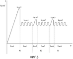
[0018] Фиг. 3 представляет диаграмму изменения электрического тока (I) относительно времени (T), подаваемого на электрический двигатель, приводящий в действие барабан стиральной машины в программе стирки в варианте осуществления представленного изобретения.[0018] FIG. 3 is a diagram of a change in electric current (I) versus time (T) applied to an electric motor driving a drum of a washing machine in a washing program in an embodiment of the present invention.
[0019] Элементы, проиллюстрированные на Фигурах, пронумерованы следующим образом:[0019] The elements illustrated in the Figures are numbered as follows:
[0020] 1 - Схема управления[0020] 1 - Control Scheme
[0021] 2 - Преобразователь[0021] 2 - Converter
[0022] 3 - Трехфазный инвертор[0022] 3 - Three-phase inverter
[0023] 4 - Блок оценки скорости и положения[0023] 4 - Block estimates the speed and position
[0024] 5 - Микроконтроллер[0024] 5 - Microcontroller
ОПИСАНИЕ ПРЕДПОЧТИТЕЛЬНЫХ ВАРИАНТОВ ВОПЛОЩЕНИЯDESCRIPTION OF PREFERRED EMBODIMENTS
[0025] Схема (1) управления, которая управляет синхронным двигателем (M) с постоянными магнитами, используемым для приведения в действие барабана в стиральных машинах, содержит преобразователь (2), который преобразует напряжение сети переменного тока в напряжение постоянного тока, трехфазный инвертор (3), который инвертирует постоянный ток, получаемый от преобразователя (2), в трехфазный ток (Ia, Ib, Ic), блок (4) оценки скорости и положения, который определяет данные, связанные с положением и скоростью ротора, посредством датчиков напряжения в процессе запуска и работы двигателя (M) и микроконтроллер (5), который обеспечивает управление двигателем (M) за счет отправки синусоидальных переключающих сигналов в трехфазный инвертор (3) с сигналами, получаемыми от блока (4) оценки скорости и положения.[0025] The control circuit (1) that controls the permanent magnet synchronous motor (M) used to drive the drum in washing machines includes a converter (2) that converts AC voltage to DC voltage, a three-phase inverter ( 3), which inverts the direct current received from the converter (2) into a three-phase current (Ia, Ib, Ic), a speed and position estimation unit (4) that detects data related to the position and speed of the rotor by means of voltage sensors in process e starting and running the motor (M) and a microcontroller (5), which provides motor control (M) by sending sinusoidal switching signals to a three-phase inverter (3) with signals received from the speed and position estimation unit (4).
[0026] Схема (1) управления управляет двигателем (M) во время выполняемой программы стирки за счет осуществления более чем одного цикла (P1, P2, ...), образованного из периодов запуска (T-st1, Tst2, ...), в которых двигатель (M) медленно ускоряется подаваемым током, начиная с положения остановки, и периодов работы в устойчивом состоянии (T-ss1, T-ss2, ...) после каждого периода запуска (T-st1, Tst2, ...), в которых двигатель (M) работает с постоянной скоростью, установленной для процесса стирки. Схема (1) управления управляет двигателем (M) за счет осуществления приблизительно 200-250 циклов (P1, P2, ...) во время программы стирки, и двигатель (M) делает движения остановки-запуска в каждом цикле (P1, P2, ...).[0026] The control circuit (1) controls the engine (M) during the washing program by performing more than one cycle (P1, P2, ...) formed from the start periods (T-st1, Tst2, ...) in which the motor (M) is slowly accelerated by the supplied current, starting from the stop position, and the periods of steady state operation (T-ss1, T-ss2, ...) after each start-up period (T-st1, Tst2, ... ), in which the engine (M) operates at a constant speed set for the washing process. The control circuit (1) controls the engine (M) by performing approximately 200-250 cycles (P1, P2, ...) during the washing program, and the engine (M) makes stop-start movements in each cycle (P1, P2, ...).
[0027] Микроконтроллер (5) предоставляет трехфазный инвертор (3) для подачи тока на двигатель (M) с величиной, которая обеспечивает запуск с максимальной нагрузкой на барабан в первом периоде запуска (T-st1) первого цикла (P1), и в периоде устойчивого состояния (T-ss1) после первого периода запуска (T-st1), после чего двигатель (M) работает с постоянной скоростью, отслеживает и измеряет токи, которые изменяют величину (значение) в зависимости от нагрузки на барабан, приводимый в действие двигателем (M), а в периоде запуска (T-st2) второго цикла (P2) подает ток, который имеет значение, равное или близкое току, измеренному в первом периоде устойчивого состояния (T-ss1).[0027] The microcontroller (5) provides a three-phase inverter (3) for supplying current to the motor (M) with a value that provides starting with maximum load on the drum in the first start-up period (T-st1) of the first cycle (P1), and in the period steady state (T-ss1) after the first start-up period (T-st1), after which the motor (M) runs at a constant speed, monitors and measures currents that change the value (value) depending on the load on the drum driven by the motor (M), and during the start-up period (T-st2) of the second cycle (P2), the current the second one has a value equal to or close to the current measured in the first period of the steady state (T-ss1).
[0028] В варианте осуществления настоящего изобретения, микроконтроллер (5) обеспечивает токи, которые равны или близки по значению токам, измеренным в первом периоде устойчивого состояния (T-ss1), которые изменяются в зависимости от нагрузки на барабан, приводимый в действие двигателем (M), подаваемые на двигатель (M) в периоды запуска (T-st2, T-st3, ...) всех циклов (P2, P3, ...) после первого цикла (P1) до конца программы стирки.[0028] In an embodiment of the present invention, the microcontroller (5) provides currents that are equal to or close to the currents measured in the first steady state period (T-ss1), which vary depending on the load on the drum driven by the motor ( M) supplied to the engine (M) during the starting periods (T-st2, T-st3, ...) of all cycles (P2, P3, ...) after the first cycle (P1) until the end of the wash program.
[0029] В варианте осуществления настоящего изобретения, микроконтроллер (5) обеспечивает токи, которые равны или близки по значению токам, измеренным в периоды устойчивого состояния (T-ss1, T-ss2, ...) предшествующего цикла (P1, P2, ...), которые изменяются в зависимости от нагрузки на барабан, приводимый в действие двигателем (M), подаваемые на двигатель (M) в периоды запуска (T-st2, T-st3, ...) всех циклов (P2, P3, ...) после первого цикла (P1) до конца программы стирки.[0029] In an embodiment of the present invention, the microcontroller (5) provides currents that are equal to or close to the currents measured during periods of steady state (T-ss1, T-ss2, ...) of the previous cycle (P1, P2,. ..), which vary depending on the load on the drum driven by the engine (M) supplied to the engine (M) during the start-up periods (T-st2, T-st3, ...) of all cycles (P2, P3, ...) after the first cycle (P1) until the end of the wash program.
[0030] В варианте осуществления настоящего изобретения, схема (1) управления управляет работой двигателя (M) методом управления с ориентацией по полю, при этом микроконтроллер (5) управляет работой двигателя (M) в периоды запуска (T-st1, Tst2, ...) за счет применения управления с разомкнутым контуром без приема сигналов обратной связи от двигателя (M) и управляет работой двигателя (M) в периоды устойчивого состояния (T-ss1, T-ss2, ...) за счет применения управления с замкнутым контуром с сигналами обратной связи, получаемыми от блока (4) оценки скорости и положения.[0030] In an embodiment of the present invention, the control circuit (1) controls the operation of the engine (M) by a field-oriented control method, while the microcontroller (5) controls the operation of the engine (M) during the start periods (T-st1, Tst2,. ..) through the use of open-loop control without receiving feedback from the engine (M) and controls the operation of the engine (M) during periods of steady state (T-ss1, T-ss2, ...) through the use of closed-loop control loop with feedback signals received from the unit (4) for estimating speed and position .
[0031] Микроконтроллер (5) измеряет фазные токи (Ia, Ib, Ic), подаваемые на двигатель (M) посредством трехфазного инвертора (3), за счет разделения их на составляющую крутящего момента (Iq) и составляющую потока (Id) и предоставляет фазные токи (Ia, Ib, Ic), имеющие составляющую крутящего момента (Iq) с максимальным значением и нулевую составляющую потока (Id), подаваемые на двигатель (M) посредством трехфазного инвертора (3) в зависимости от требуемого момента в программе стирки.[0031] The microcontroller (5) measures the phase currents (Ia, Ib, Ic) supplied to the motor (M) by means of a three-phase inverter (3), by dividing them into a torque component (Iq) and a flow component (Id) and provides phase currents (Ia, Ib, Ic) having a torque component (Iq) with a maximum value and zero flow component (Id) supplied to the motor (M) via a three-phase inverter (3) depending on the required moment in the washing program.
[0032] Составляющая потока (Id) обеспечивает ускорение двигателя (M), и во время стадии отжима стиральной машины, в которой используется двигатель (M), значение составляющей крутящего момента (Iq) тока уменьшается, а значение составляющей потока (Id) увеличивается. Вариант осуществления представленного изобретения применим для процесса стирки в стиральной машине, в котором требуется высокий крутящий момент при низкой скорости, а значения фазных токов (Ia, Ib, Ic), подаваемых на двигатель (M), увеличиваются/уменьшаются только за счет регулирования составляющих момента (Iq) фазных токов (Ia, Ib, Ic).[0032] The flow component (Id) accelerates the motor (M), and during the spin phase of the washing machine using the motor (M), the value of the current component (Iq) decreases and the value of the flow component (Id) increases. An embodiment of the present invention is applicable to a washing process in a washing machine that requires high torque at low speed, and the phase currents (Ia, Ib, Ic) supplied to the motor (M) increase / decrease only by adjusting the moment components (Iq) phase currents (Ia, Ib, Ic).
[0033] В варианте осуществления настоящего изобретения, микроконтроллер (5), в периоде запуска (T-st2) второго цикла (P2), обеспечивает составляющую крутящего момента (Iq-st2), подаваемую на двигатель (M), которая равна среднему значению составляющих крутящего момента (Iq-ss1), измеренных в период устойчивого состояния (Tss-1) первого цикла (P1), или приблизительно среднему значению указанной составляющей крутящего момента (Iq-ss1) посредством измерения составляющей крутящего момента (Iq) фазных токов (Ia, Ib, Ic), подаваемых на двигатель (M) в период устойчивого состояния (T-ss1) первого цикла (P1) (Фиг. 3).[0033] In an embodiment of the present invention, the microcontroller (5), during the start-up period (T-st2) of the second cycle (P2), provides a torque component (Iq-st2) supplied to the engine (M), which is equal to the average value of the components torque (Iq-ss1) measured during the steady state period (Tss-1) of the first cycle (P1), or approximately the average value of the specified torque component (Iq-ss1) by measuring the torque component (Iq) of the phase currents (Ia, Ib, Ic) supplied to the engine (M) during steady state Nia (T-ss1) the first cycle (P1) (FIG. 3).
[0034] В еще одном варианте осуществления настоящего изобретения, микроконтроллер (5) обеспечивает составляющие крутящего момента (Iq-st2, Iq-st3), подаваемые на двигатель (M), которые равны среднему значению составляющих крутящего момента (Iq-ss1), измеренных в период устойчивого состояния (Tss-1) первого цикла (P1), или приблизительно среднему значению указанной составляющей крутящего момента (Iq-ss1), в периоды запуска (T-st2, T-st3, ...) всех циклов (P2, P3, ...) после первого цикла (P1) (Фиг. 3).[0034] In yet another embodiment of the present invention, the microcontroller (5) provides torque components (Iq-st2, Iq-st3) supplied to the engine (M) that are equal to the average value of the torque components (Iq-ss1) measured during the steady state period (Tss-1) of the first cycle (P1), or approximately the average value of the specified torque component (Iq-ss1), during the start periods (T-st2, T-st3, ...) of all cycles (P2, P3, ...) after the first cycle (P1) (Fig. 3).
[0035] В еще одном варианте осуществления настоящего изобретения, микроконтроллер (5) обеспечивает составляющие крутящего момента (Iq-st2, Iq-st3, ...), подаваемые на двигатель (M), которые равны среднему значению составляющих крутящего момента (Iq-ss1, Iq-ss2, ...), измеренных в периоды устойчивого состояния (T-ss1, T-ss2, ...) предшествующего цикла (P1, P2), или приблизительно среднему значению указанных составляющих крутящего момента (Iq-ss1, Iq-ss2, ...) в периоды запуска (T-st2, T-st3, ...) всех циклов (P2, P3, ...) после первого цикла (P1) до конца программы стирки.[0035] In yet another embodiment of the present invention, the microcontroller (5) provides torque components (Iq-st2, Iq-st3, ...) supplied to the engine (M), which are equal to the average value of the torque components (Iq- ss1, Iq-ss2, ...) measured during periods of steady state (T-ss1, T-ss2, ...) of the previous cycle (P1, P2), or approximately the average value of the specified components of the torque (Iq-ss1, Iq-ss2, ...) during the start periods (T-st2, T-st3, ...) of all cycles (P2, P3, ...) after the first cycle (P1) until the end of the wash program.
[0036] Микроконтроллер (5) подает фазные токи (Ia, Ib, Ic), имеющие опорную составляющую крутящего момента (Iq-ref), и рассчитанные согласно максимальной нагрузке барабана, приводимого в действие двигателем (M) в первом периоде запуска (T-st1) двигателя (M), а после того как движение запуска выполнено и двигатель (M) достигает постоянной скорости, установленной для программы стирки, измеряет составляющую крутящего момента (Iq-ss1) фазных токов (Ia, Ib, Ic), подаваемых на двигатель (M) в период устойчивого состояния (T-ss1) первого цикла (P1). Микроконтроллер (5) обеспечивает подачу трехфазным инвертором (3) на двигатель (M) фазных токов (Ia, Ib, Ic), имеющих составляющие крутящего момента (Iq-st2, Iq-st3, ...), равные или близкие по значению составляющей крутящего момента (Iq-ss1) в период устойчивого состояния (T-ss1) первого цикла (P1) или составляющим крутящего момента (Iq-ss1, Iq-ss2, ...) в устойчивом состоянии предшествующего цикла (P1, P2..) перед каждым циклом (P2, P3, ...), в периоды запуска (T-st2, T-st3, ...) всех циклов (P2, P3, P4, ...) после первого цикла (P1) до конца программы стирки.[0036] The microcontroller (5) supplies phase currents (Ia, Ib, Ic) having a torque reference component (Iq-ref) and calculated according to the maximum load of the drum driven by the motor (M) in the first starting period (T- st1) of the motor (M), and after the starting movement is completed and the motor (M) reaches the constant speed set for the washing program, it measures the torque component (Iq-ss1) of the phase currents (Ia, Ib, Ic) supplied to the motor (M) during the steady state period (T-ss1) of the first cycle (P1). The microcontroller (5) supplies three-phase inverter (3) to the motor (M) of phase currents (Ia, Ib, Ic) having torque components (Iq-st2, Iq-st3, ...) equal or close in value to the component torque (Iq-ss1) during the steady state period (T-ss1) of the first cycle (P1) or torque components (Iq-ss1, Iq-ss2, ...) in the steady state of the previous cycle (P1, P2 ..) before each cycle (P2, P3, ...), during the start periods (T-st2, T-st3, ...) of all cycles (P2, P3, P4, ...) after the first cycle (P1) to the end washing programs.
[0037] Микроконтроллер (5), кроме того, определяет, что длина продолжительностей запуска, другими словами периоды запуска (T-st2, T-st3, ...) всех циклов (P2, P3, P4, ...) после первого цикла (P1), находилась в прямой зависимости от значений составляющих крутящего момента (Iq-st2, Iq-st3, ...), подаваемых согласно составляющей крутящего момента (Iq-ss1) в первом периоде устойчивого состояния (T-ss1) в конце программы стирки, выполняемой в стиральной машине, в которой используется двигатель (M). По мере того, как значение пусковых составляющих крутящего момента (Iq-st2, Iq-st3, ...) увеличивается, периоды запуска (T-st2, T-st3, ...) двигателя (M) в циклах (P2, P3, P4, ...) после первого цикла (P1) становятся длиннее, а по мере того, как значение пусковых составляющих крутящего момента (Iq-st2, Iq-st3, ...) уменьшается, периоды запуска (T-st2, T-st3, ...) двигателя (M) в циклах (P2, P3, P4, ...) после первого цикла (P1) уменьшаются.[0037] The microcontroller (5) further determines that the length of the start durations, in other words, the start periods (T-st2, T-st3, ...) of all cycles (P2, P3, P4, ...) after the first cycle (P1), was directly dependent on the values of the components of the torque (Iq-st2, Iq-st3, ...) supplied according to the component of the torque (Iq-ss1) in the first period of the steady state (T-ss1) at the end washing program in a washing machine that uses an engine (M). As the value of the starting components of the torque (Iq-st2, Iq-st3, ...) increases, the starting periods (T-st2, T-st3, ...) of the engine (M) in cycles (P2, P3 , P4, ...) after the first cycle (P1) become longer, and as the value of the starting components of the torque (Iq-st2, Iq-st3, ...) decreases, the start periods (T-st2, T -st3, ...) of the motor (M) in cycles (P2, P3, P4, ...) after the first cycle (P1) are reduced.
[0038] Схема (1) управления настоящего изобретения подает пусковой ток максимального значения на двигатель (M) в период запуска (T-st1) первого цикла (P1) в программе стирки белья с величиной, которая может обеспечивать запуск в каждом состоянии нагрузки на барабан и подает токи в зависимости от нагрузки, установленной в период устойчивого состояния (T-ss1) первого цикла (P1) в периоды запуска (T-st2, T-st3, ...) циклов (P2, P3, P4, ...) после первого цикла (P1). За счет применения пусковых токов в зависимости от нагрузки на барабан предотвращаются тяжелые запуски и перегрев двигателя (M), и обеспечивается экономия энергии. В варианте осуществления представленного изобретения, пусковые токи подаются на двигатель (M) в зависимости от нагрузки на барабан только за счет создания изменений программного обеспечения в микроконтроллере (5), для управления током относительно нагрузки на барабан не требуется использование датчика массы и датчика ускорения.[0038] The control circuit (1) of the present invention supplies an inrush current of maximum value to the motor (M) during the start-up period (T-st1) of the first cycle (P1) in the laundry program with a value that can ensure that the drum load starts in each state and supplies currents depending on the load set during the steady state period (T-ss1) of the first cycle (P1) during the start-up periods (T-st2, T-st3, ...) of the cycles (P2, P3, P4, ... ) after the first cycle (P1). Due to the application of inrush currents depending on the load on the drum, heavy starts and overheating of the engine (M) are prevented and energy savings are ensured. In an embodiment of the invention, inrush currents are supplied to the motor (M) depending on the load on the drum only by creating software changes in the microcontroller (5), to control the current relative to the load on the drum, the use of a mass sensor and an acceleration sensor is not required.
[0039] Должно быть понятно, что настоящее изобретение не ограничено вариантами осуществления, обсуждавшимися выше, и квалифицированный специалист в данной области легко может внедрить различные варианты осуществления. Они должны рассматриваться в пределах объема правовых притязаний, раскрытого формулой представленного изобретения.[0039] It should be understood that the present invention is not limited to the embodiments discussed above, and one skilled in the art can easily implement various embodiments. They should be considered within the scope of legal claims disclosed by the claims presented.
Claims (8)
отличающаяся тем, что микроконтроллер (5),
- управляет двигателем (M) во время программы стирки за счет осуществления более чем одного цикла (P1, P2, ...), образованного из периодов запуска (T-st1, T-st2, ...) и периодов устойчивого состояния (T-ss1, T-ss2, ...), после каждого периода запуска (T-st1, T-st2, ...), при этом двигатель (M) работает с постоянной скоростью,
- подает ток на двигатель (M) с величиной, обеспечивающей запуск в состоянии максимальной нагрузки в первом периоде запуска (T-st1) первого цикла (P1),
- отслеживает и измеряет токи, которые изменяются по значению в зависимости от нагрузки на барабан, приводимый в действие двигателем (M) в первом периоде устойчивого состояния (T-ss1) после первого периода запуска (T-st1), при этом двигатель (M) работает с постоянной скоростью, и
- обеспечивает ток, подаваемый на двигатель (M) в период запуска (T-st2) второго цикла (P2), который равен или близок по значению токам, измеренным в первом периоде устойчивого состояния (T-ss1).1. A control circuit (1) that controls a permanent magnet synchronous motor (M) used to drive a drum in washing machines, comprising a converter (2) that converts AC voltage to DC voltage, a three-phase inverter (3 ), which inverts the direct current received from the converter (2) into a three-phase current (Ia, Ib, Ic), a speed and position estimation unit (4), which determines data related to the position and speed of the rotor during engine start-up and operation (M) and mi rokontroller (5) that provides motor control (M) by sending switching signals sinusoidal three-phase inverter (3) from signals received from the unit (4) estimates the speed and position of,
characterized in that the microcontroller (5),
- controls the engine (M) during the washing program due to the implementation of more than one cycle (P1, P2, ...) formed from the start periods (T-st1, T-st2, ...) and periods of steady state (T -ss1, T-ss2, ...), after each start-up period (T-st1, T-st2, ...), while the engine (M) runs at a constant speed,
- supplies current to the engine (M) with a value that ensures starting in the state of maximum load in the first starting period (T-st1) of the first cycle (P1),
- monitors and measures currents that change in value depending on the load on the drum, driven by the motor (M) in the first period of the steady state (T-ss1) after the first start-up period (T-st1), while the motor (M) runs at a constant speed, and
- provides the current supplied to the motor (M) during the start-up period (T-st2) of the second cycle (P2), which is equal to or close to the currents measured in the first period of the steady state (T-ss1).
Applications Claiming Priority (3)
| Application Number | Priority Date | Filing Date | Title |
|---|---|---|---|
| TRA2010/11100 | 2010-12-29 | ||
| TR201011100 | 2010-12-29 | ||
| PCT/EP2011/072050 WO2012089466A2 (en) | 2010-12-29 | 2011-12-07 | Permanent magnet synchronous motor control circuit |
Publications (2)
| Publication Number | Publication Date |
|---|---|
| RU2013135270A RU2013135270A (en) | 2015-02-10 |
| RU2543998C1 true RU2543998C1 (en) | 2015-03-10 |
Family
ID=45422123
Family Applications (1)
| Application Number | Title | Priority Date | Filing Date |
|---|---|---|---|
| RU2013135270/07A RU2543998C1 (en) | 2010-12-29 | 2011-12-07 | Control circuit of synchronous motor with permanent magnets |
Country Status (4)
| Country | Link |
|---|---|
| EP (1) | EP2659583B1 (en) |
| CN (1) | CN103380568B (en) |
| RU (1) | RU2543998C1 (en) |
| WO (1) | WO2012089466A2 (en) |
Families Citing this family (5)
| Publication number | Priority date | Publication date | Assignee | Title |
|---|---|---|---|---|
| CN105099293A (en) * | 2014-04-30 | 2015-11-25 | 合肥美的洗衣机有限公司 | Inverter pulsator washing machine and control method thereof |
| CN104767445B (en) * | 2015-03-30 | 2017-04-05 | 北京空间机电研究所 | A kind of mounted permasyn morot method for controlling torque in face of no current feedback |
| DE102019200425A1 (en) | 2019-01-16 | 2020-07-16 | BSH Hausgeräte GmbH | Control device and method for a laundry care appliance |
| DE102019200426A1 (en) | 2019-01-16 | 2020-07-16 | BSH Hausgeräte GmbH | Control device and method for a laundry care appliance |
| TWI705653B (en) * | 2020-03-20 | 2020-09-21 | 財團法人工業技術研究院 | Device and method for determining dc current |
Citations (6)
| Publication number | Priority date | Publication date | Assignee | Title |
|---|---|---|---|---|
| RU2141719C1 (en) * | 1998-03-25 | 1999-11-20 | Мищенко Владислав Алексеевич | Method and electric drive for vector control of permanent-magnet synchronous motor |
| WO2003050341A1 (en) * | 2001-12-13 | 2003-06-19 | Kabushiki Kaisha Toshiba | Inverter of washing machine and inverter of washing machine/dryer |
| JP3962668B2 (en) * | 2002-09-24 | 2007-08-22 | 株式会社東芝 | Drum washing machine |
| US20090267546A1 (en) * | 2008-04-23 | 2009-10-29 | Kabushiki Kaisha Toshiba | Motor control device, motor drive system, washing machine, air conditioner and method of changing magnetization amount of permanent magnet motor |
| EP2219289A1 (en) * | 2007-11-07 | 2010-08-18 | Kabushiki Kaisha Toshiba | Inverter device for washing machine |
| RU2407140C1 (en) * | 2006-10-19 | 2010-12-20 | Мицубиси Электрик Корпорейшн | Vector controller for synchronous electric motor with permanent magnets |
Family Cites Families (5)
| Publication number | Priority date | Publication date | Assignee | Title |
|---|---|---|---|---|
| CN1015999B (en) * | 1984-12-19 | 1992-03-25 | 三洋电机株式会社 | Washer with spin dryer |
| TW584688B (en) * | 2001-06-06 | 2004-04-21 | Toshiba Corp | Washing machine |
| GB0421443D0 (en) * | 2004-09-27 | 2004-10-27 | Unsworth Peter | Point on wave (pow) control for motor starting and switching |
| US7542250B2 (en) * | 2007-01-10 | 2009-06-02 | General Electric Company | Micro-electromechanical system based electric motor starter |
| US7638959B2 (en) | 2007-12-14 | 2009-12-29 | Hamilton Sundstrand Corporation | Method of operating a brushless motor wherein open loop and closed loop controllers utilize different commutation methods |
-
2011
- 2011-12-07 EP EP11802682.2A patent/EP2659583B1/en active Active
- 2011-12-07 CN CN201180068718.9A patent/CN103380568B/en not_active Expired - Fee Related
- 2011-12-07 RU RU2013135270/07A patent/RU2543998C1/en not_active IP Right Cessation
- 2011-12-07 WO PCT/EP2011/072050 patent/WO2012089466A2/en active Application Filing
Patent Citations (7)
| Publication number | Priority date | Publication date | Assignee | Title |
|---|---|---|---|---|
| RU2141719C1 (en) * | 1998-03-25 | 1999-11-20 | Мищенко Владислав Алексеевич | Method and electric drive for vector control of permanent-magnet synchronous motor |
| WO2003050341A1 (en) * | 2001-12-13 | 2003-06-19 | Kabushiki Kaisha Toshiba | Inverter of washing machine and inverter of washing machine/dryer |
| US7579798B2 (en) * | 2001-12-13 | 2009-08-25 | Kabushiki Kaisha Toshiba | Inverter for washer and inverter for washer-drier |
| JP3962668B2 (en) * | 2002-09-24 | 2007-08-22 | 株式会社東芝 | Drum washing machine |
| RU2407140C1 (en) * | 2006-10-19 | 2010-12-20 | Мицубиси Электрик Корпорейшн | Vector controller for synchronous electric motor with permanent magnets |
| EP2219289A1 (en) * | 2007-11-07 | 2010-08-18 | Kabushiki Kaisha Toshiba | Inverter device for washing machine |
| US20090267546A1 (en) * | 2008-04-23 | 2009-10-29 | Kabushiki Kaisha Toshiba | Motor control device, motor drive system, washing machine, air conditioner and method of changing magnetization amount of permanent magnet motor |
Also Published As
| Publication number | Publication date |
|---|---|
| CN103380568B (en) | 2015-12-09 |
| WO2012089466A3 (en) | 2013-05-23 |
| EP2659583A2 (en) | 2013-11-06 |
| EP2659583B1 (en) | 2015-08-05 |
| WO2012089466A2 (en) | 2012-07-05 |
| RU2013135270A (en) | 2015-02-10 |
| CN103380568A (en) | 2013-10-30 |
Similar Documents
| Publication | Publication Date | Title |
|---|---|---|
| EP2212991B1 (en) | Motor performing vector control in a start mode | |
| US20080297098A1 (en) | Washing machine apparatus and method | |
| RU2543998C1 (en) | Control circuit of synchronous motor with permanent magnets | |
| KR102595183B1 (en) | Motor for washing machine and Washing machine having the same | |
| Iura et al. | An estimation method of rotational direction and speed for free-running ac machines without speed and voltage sensor | |
| JP3915557B2 (en) | Motor drive device for washing machine | |
| JP4238497B2 (en) | Motor drive device for washing machine | |
| US9577552B2 (en) | Systems and methods for braking an electric motor | |
| US8952648B2 (en) | Washing machine with improved braking method | |
| JP3858754B2 (en) | Motor drive device for laundry equipment | |
| US8390229B2 (en) | Washing machine with improved method of braking to a non-zero speed | |
| JP2003135883A (en) | Motor drive of washing machine | |
| Renu et al. | Sensorless control of permanent magnet synchronous motor with flux weakening operation for washing machine application | |
| US8907600B2 (en) | Systems, methods, and assemblies for detecting stoppage of electric motors | |
| Murray et al. | Performance comparison of permanent magnet synchronous motors and controlled induction motors in washing machine applications using sensorless field oriented control | |
| CN104838055A (en) | Drum drive device, and clothes washer and clothes dryer using same | |
| JP4103354B2 (en) | Motor drive device for washing machine | |
| JP6043950B2 (en) | Washing and drying machine | |
| JP7522964B2 (en) | washing machine | |
| CN110904615B (en) | Brushless direct current motor control method and system for washing machine | |
| KR20090087242A (en) | Motor, washing machine comprising the motor and method of controlling the washing machine | |
| KR100811659B1 (en) | Method for control starting of compressor including brushless dc motor | |
| KR20090081051A (en) | motor, controlling apparatus for the motor, controlling method for the motor, and washing machine | |
| WIN | Speed Controller Design of Permanent Magnet Synchronous Motor used in Washing Machine | |
| KR20090081050A (en) | Motor and controlling system for the motor, controlling method for the motor, and waching machine |
Legal Events
| Date | Code | Title | Description |
|---|---|---|---|
| MM4A | The patent is invalid due to non-payment of fees |
Effective date: 20181208 |