RU2541084C2 - Turbo-supercharged engine with recirculation of exhaust gases - Google Patents
Turbo-supercharged engine with recirculation of exhaust gases Download PDFInfo
- Publication number
- RU2541084C2 RU2541084C2 RU2011138030/06A RU2011138030A RU2541084C2 RU 2541084 C2 RU2541084 C2 RU 2541084C2 RU 2011138030/06 A RU2011138030/06 A RU 2011138030/06A RU 2011138030 A RU2011138030 A RU 2011138030A RU 2541084 C2 RU2541084 C2 RU 2541084C2
- Authority
- RU
- Russia
- Prior art keywords
- exhaust
- inlet
- compressor
- outlet
- turbocharger
- Prior art date
Links
Images
Classifications
-
- F—MECHANICAL ENGINEERING; LIGHTING; HEATING; WEAPONS; BLASTING
- F02—COMBUSTION ENGINES; HOT-GAS OR COMBUSTION-PRODUCT ENGINE PLANTS
- F02M—SUPPLYING COMBUSTION ENGINES IN GENERAL WITH COMBUSTIBLE MIXTURES OR CONSTITUENTS THEREOF
- F02M26/00—Engine-pertinent apparatus for adding exhaust gases to combustion-air, main fuel or fuel-air mixture, e.g. by exhaust gas recirculation [EGR] systems
- F02M26/02—EGR systems specially adapted for supercharged engines
- F02M26/08—EGR systems specially adapted for supercharged engines for engines having two or more intake charge compressors or exhaust gas turbines, e.g. a turbocharger combined with an additional compressor
-
- F—MECHANICAL ENGINEERING; LIGHTING; HEATING; WEAPONS; BLASTING
- F01—MACHINES OR ENGINES IN GENERAL; ENGINE PLANTS IN GENERAL; STEAM ENGINES
- F01N—GAS-FLOW SILENCERS OR EXHAUST APPARATUS FOR MACHINES OR ENGINES IN GENERAL; GAS-FLOW SILENCERS OR EXHAUST APPARATUS FOR INTERNAL COMBUSTION ENGINES
- F01N5/00—Exhaust or silencing apparatus combined or associated with devices profiting from exhaust energy
- F01N5/04—Exhaust or silencing apparatus combined or associated with devices profiting from exhaust energy the devices using kinetic energy
-
- F—MECHANICAL ENGINEERING; LIGHTING; HEATING; WEAPONS; BLASTING
- F02—COMBUSTION ENGINES; HOT-GAS OR COMBUSTION-PRODUCT ENGINE PLANTS
- F02B—INTERNAL-COMBUSTION PISTON ENGINES; COMBUSTION ENGINES IN GENERAL
- F02B37/00—Engines characterised by provision of pumps driven at least for part of the time by exhaust
- F02B37/001—Engines characterised by provision of pumps driven at least for part of the time by exhaust using exhaust drives arranged in parallel
-
- F—MECHANICAL ENGINEERING; LIGHTING; HEATING; WEAPONS; BLASTING
- F02—COMBUSTION ENGINES; HOT-GAS OR COMBUSTION-PRODUCT ENGINE PLANTS
- F02B—INTERNAL-COMBUSTION PISTON ENGINES; COMBUSTION ENGINES IN GENERAL
- F02B37/00—Engines characterised by provision of pumps driven at least for part of the time by exhaust
- F02B37/007—Engines characterised by provision of pumps driven at least for part of the time by exhaust with exhaust-driven pumps arranged in parallel, e.g. at least one pump supplying alternatively
-
- F—MECHANICAL ENGINEERING; LIGHTING; HEATING; WEAPONS; BLASTING
- F02—COMBUSTION ENGINES; HOT-GAS OR COMBUSTION-PRODUCT ENGINE PLANTS
- F02B—INTERNAL-COMBUSTION PISTON ENGINES; COMBUSTION ENGINES IN GENERAL
- F02B39/00—Component parts, details, or accessories relating to, driven charging or scavenging pumps, not provided for in groups F02B33/00 - F02B37/00
- F02B39/02—Drives of pumps; Varying pump drive gear ratio
- F02B39/08—Non-mechanical drives, e.g. fluid drives having variable gear ratio
- F02B39/10—Non-mechanical drives, e.g. fluid drives having variable gear ratio electric
-
- F—MECHANICAL ENGINEERING; LIGHTING; HEATING; WEAPONS; BLASTING
- F02—COMBUSTION ENGINES; HOT-GAS OR COMBUSTION-PRODUCT ENGINE PLANTS
- F02M—SUPPLYING COMBUSTION ENGINES IN GENERAL WITH COMBUSTIBLE MIXTURES OR CONSTITUENTS THEREOF
- F02M26/00—Engine-pertinent apparatus for adding exhaust gases to combustion-air, main fuel or fuel-air mixture, e.g. by exhaust gas recirculation [EGR] systems
- F02M26/13—Arrangement or layout of EGR passages, e.g. in relation to specific engine parts or for incorporation of accessories
- F02M26/17—Arrangement or layout of EGR passages, e.g. in relation to specific engine parts or for incorporation of accessories in relation to the intake system
- F02M26/19—Means for improving the mixing of air and recirculated exhaust gases, e.g. venturis or multiple openings to the intake system
-
- F—MECHANICAL ENGINEERING; LIGHTING; HEATING; WEAPONS; BLASTING
- F02—COMBUSTION ENGINES; HOT-GAS OR COMBUSTION-PRODUCT ENGINE PLANTS
- F02M—SUPPLYING COMBUSTION ENGINES IN GENERAL WITH COMBUSTIBLE MIXTURES OR CONSTITUENTS THEREOF
- F02M26/00—Engine-pertinent apparatus for adding exhaust gases to combustion-air, main fuel or fuel-air mixture, e.g. by exhaust gas recirculation [EGR] systems
- F02M26/13—Arrangement or layout of EGR passages, e.g. in relation to specific engine parts or for incorporation of accessories
- F02M26/34—Arrangement or layout of EGR passages, e.g. in relation to specific engine parts or for incorporation of accessories with compressors, turbines or the like in the recirculation passage
-
- F—MECHANICAL ENGINEERING; LIGHTING; HEATING; WEAPONS; BLASTING
- F02—COMBUSTION ENGINES; HOT-GAS OR COMBUSTION-PRODUCT ENGINE PLANTS
- F02M—SUPPLYING COMBUSTION ENGINES IN GENERAL WITH COMBUSTIBLE MIXTURES OR CONSTITUENTS THEREOF
- F02M26/00—Engine-pertinent apparatus for adding exhaust gases to combustion-air, main fuel or fuel-air mixture, e.g. by exhaust gas recirculation [EGR] systems
- F02M26/13—Arrangement or layout of EGR passages, e.g. in relation to specific engine parts or for incorporation of accessories
- F02M26/41—Arrangement or layout of EGR passages, e.g. in relation to specific engine parts or for incorporation of accessories characterised by the arrangement of the recirculation passage in relation to the engine, e.g. to cylinder heads, liners, spark plugs or manifolds; characterised by the arrangement of the recirculation passage in relation to specially adapted combustion chambers
-
- F—MECHANICAL ENGINEERING; LIGHTING; HEATING; WEAPONS; BLASTING
- F02—COMBUSTION ENGINES; HOT-GAS OR COMBUSTION-PRODUCT ENGINE PLANTS
- F02M—SUPPLYING COMBUSTION ENGINES IN GENERAL WITH COMBUSTIBLE MIXTURES OR CONSTITUENTS THEREOF
- F02M26/00—Engine-pertinent apparatus for adding exhaust gases to combustion-air, main fuel or fuel-air mixture, e.g. by exhaust gas recirculation [EGR] systems
- F02M26/13—Arrangement or layout of EGR passages, e.g. in relation to specific engine parts or for incorporation of accessories
- F02M26/42—Arrangement or layout of EGR passages, e.g. in relation to specific engine parts or for incorporation of accessories having two or more EGR passages; EGR systems specially adapted for engines having two or more cylinders
-
- F—MECHANICAL ENGINEERING; LIGHTING; HEATING; WEAPONS; BLASTING
- F01—MACHINES OR ENGINES IN GENERAL; ENGINE PLANTS IN GENERAL; STEAM ENGINES
- F01N—GAS-FLOW SILENCERS OR EXHAUST APPARATUS FOR MACHINES OR ENGINES IN GENERAL; GAS-FLOW SILENCERS OR EXHAUST APPARATUS FOR INTERNAL COMBUSTION ENGINES
- F01N13/00—Exhaust or silencing apparatus characterised by constructional features ; Exhaust or silencing apparatus, or parts thereof, having pertinent characteristics not provided for in, or of interest apart from, groups F01N1/00 - F01N5/00, F01N9/00, F01N11/00
- F01N13/08—Other arrangements or adaptations of exhaust conduits
- F01N13/10—Other arrangements or adaptations of exhaust conduits of exhaust manifolds
- F01N13/107—More than one exhaust manifold or exhaust collector
-
- F—MECHANICAL ENGINEERING; LIGHTING; HEATING; WEAPONS; BLASTING
- F02—COMBUSTION ENGINES; HOT-GAS OR COMBUSTION-PRODUCT ENGINE PLANTS
- F02B—INTERNAL-COMBUSTION PISTON ENGINES; COMBUSTION ENGINES IN GENERAL
- F02B29/00—Engines characterised by provision for charging or scavenging not provided for in groups F02B25/00, F02B27/00 or F02B33/00 - F02B39/00; Details thereof
- F02B29/04—Cooling of air intake supply
- F02B29/0406—Layout of the intake air cooling or coolant circuit
-
- F—MECHANICAL ENGINEERING; LIGHTING; HEATING; WEAPONS; BLASTING
- F02—COMBUSTION ENGINES; HOT-GAS OR COMBUSTION-PRODUCT ENGINE PLANTS
- F02M—SUPPLYING COMBUSTION ENGINES IN GENERAL WITH COMBUSTIBLE MIXTURES OR CONSTITUENTS THEREOF
- F02M26/00—Engine-pertinent apparatus for adding exhaust gases to combustion-air, main fuel or fuel-air mixture, e.g. by exhaust gas recirculation [EGR] systems
- F02M26/13—Arrangement or layout of EGR passages, e.g. in relation to specific engine parts or for incorporation of accessories
- F02M26/17—Arrangement or layout of EGR passages, e.g. in relation to specific engine parts or for incorporation of accessories in relation to the intake system
- F02M26/20—Feeding recirculated exhaust gases directly into the combustion chambers or into the intake runners
-
- F—MECHANICAL ENGINEERING; LIGHTING; HEATING; WEAPONS; BLASTING
- F02—COMBUSTION ENGINES; HOT-GAS OR COMBUSTION-PRODUCT ENGINE PLANTS
- F02M—SUPPLYING COMBUSTION ENGINES IN GENERAL WITH COMBUSTIBLE MIXTURES OR CONSTITUENTS THEREOF
- F02M26/00—Engine-pertinent apparatus for adding exhaust gases to combustion-air, main fuel or fuel-air mixture, e.g. by exhaust gas recirculation [EGR] systems
- F02M26/13—Arrangement or layout of EGR passages, e.g. in relation to specific engine parts or for incorporation of accessories
- F02M26/22—Arrangement or layout of EGR passages, e.g. in relation to specific engine parts or for incorporation of accessories with coolers in the recirculation passage
- F02M26/23—Layout, e.g. schematics
-
- Y—GENERAL TAGGING OF NEW TECHNOLOGICAL DEVELOPMENTS; GENERAL TAGGING OF CROSS-SECTIONAL TECHNOLOGIES SPANNING OVER SEVERAL SECTIONS OF THE IPC; TECHNICAL SUBJECTS COVERED BY FORMER USPC CROSS-REFERENCE ART COLLECTIONS [XRACs] AND DIGESTS
- Y02—TECHNOLOGIES OR APPLICATIONS FOR MITIGATION OR ADAPTATION AGAINST CLIMATE CHANGE
- Y02T—CLIMATE CHANGE MITIGATION TECHNOLOGIES RELATED TO TRANSPORTATION
- Y02T10/00—Road transport of goods or passengers
- Y02T10/10—Internal combustion engine [ICE] based vehicles
- Y02T10/12—Improving ICE efficiencies
Landscapes
- Engineering & Computer Science (AREA)
- Chemical & Material Sciences (AREA)
- Combustion & Propulsion (AREA)
- Mechanical Engineering (AREA)
- General Engineering & Computer Science (AREA)
- Supercharger (AREA)
- Exhaust-Gas Circulating Devices (AREA)
Abstract
Description
Настоящее изобретение относится к двигателю с турбонаддувом и рециркуляцией выхлопных газов, например дизельному двигателю внутреннего сгорания, адаптированному для использования, например, в автомобилях большой грузоподъемности, кораблях или энергоустановках, но неограниченному до этих применений.The present invention relates to a turbocharged engine with exhaust gas recirculation, for example a diesel internal combustion engine, adapted for use, for example, in heavy vehicles, ships or power plants, but unlimited to these applications.
Турбонаддув является распространенным средством увеличения крутящего момента и мощности двигателя внутреннего сгорания. Рециркуляция выхлопных газов является распространенным средством для повышения качества выхлопных газов, т.е. снижения содержания двуокиси азота в выхлопных газах. При комбинировании внешней рециркуляции выхлопных газов (т.е. при направлении некоторой части выхлопных газов из выпускного коллектора двигателя во впускной коллектор двигателя) с турбонаддувом необходимо увеличивать давление выхлопных газов, рециркулируемых во впускной коллектор, до уровня давления, который, по меньшей мере, является таким же, как уровень давления сжимаемого приточного воздуха во впускном коллекторе.Turbocharging is a common means of increasing the torque and power of an internal combustion engine. Exhaust gas recirculation is a common means to improve exhaust quality, i.e. reduction of nitrogen dioxide in the exhaust gases. When combining external exhaust gas recirculation (i.e., when a certain portion of the exhaust gas is directed from the engine exhaust manifold to the engine intake manifold) with a turbocharger, it is necessary to increase the pressure of the exhaust gases recirculated to the intake manifold to a pressure level that is at least the same as the pressure level of the compressible supply air in the intake manifold.
В документе DE 19603591 С1 раскрыт двигатель внутреннего сгорания с турбонаддувом с турбонагнетателем приточного воздуха и турбонагнетателем выхлопных газов, в котором воздуховод выхлопных газов соединен с впуском турбины турбонагнетателя выхлопных газов и впуском турбины турбонагнетателя приточного воздуха и, кроме того, с впуском компрессора турбонагнетателя выхлопных газов. Выпуск турбонагнетателя выхлопных газов соединен с воздуховодом, соединяющим выпуск компрессора турбонагнетателя приточного воздуха с двигателем. Перед компрессором турбонагнетателя выхлопных газов и за компрессором турбонагнетателя приточного воздуха установлены охладители. Управляющий клапан соединен с впусками компрессора и турбины турбонагнетателя выхлопных газов и выпуском выхлопных газов двигателя для управления скоростью рециркуляции выхлопных газов.DE 1960 3591 C1 discloses a turbocharged internal combustion engine with a supply air turbocharger and an exhaust turbocharger, in which an exhaust gas duct is connected to an exhaust turbocharger turbine inlet and a supply air turbocharger turbine inlet, and furthermore, an exhaust turbocharger compressor inlet. The exhaust turbocharger outlet is connected to an air duct connecting the outlet of the supply air turbocharger compressor to the engine. Coolers are installed in front of the exhaust turbocharger compressor and behind the supply air turbocharger compressor. The control valve is connected to the inlet of the compressor and the turbine of the exhaust turbocharger and the exhaust of the engine to control the exhaust gas recirculation rate.
В документе DE 4436732 А1 раскрыт двигатель внутреннего сгорания с турбонаддувом с турбонагнетателем приточного воздуха и турбонагнетателем выхлопных газов с впусками их турбин, соединенными параллельно стороне выхлопа двигателя. Кроме того, сторона выхлопа двигателя соединена через охладитель с впуском компрессора турбонагнетателя выхлопных газов. Выпуск компрессора турбонагнетателя выхлопных газов соединен с впускным коллектором двигателя внутреннего сгорания, и этот впускной коллектор также соединен через охладитель с выпуском компрессора турбонагнетателя приточного воздуха. С целью управления скоростью рециркуляции выхлопных газов перед впуском турбины турбонагнетателя выхлопных газов установлен управляющий клапан.DE 44 36 732 A1 discloses a turbocharged internal combustion engine with a supply air turbocharger and an exhaust turbocharger with turbine inlets connected in parallel to the exhaust side of the engine. In addition, the exhaust side of the engine is connected through a cooler to the inlet of the exhaust turbocharger compressor. The exhaust outlet of the exhaust turbocharger compressor is connected to the intake manifold of the internal combustion engine, and this intake manifold is also connected via a cooler to the outlet of the supply air turbocharger compressor. In order to control the exhaust gas recirculation rate, a control valve is installed in front of the turbine inlet of the exhaust gas turbine inlet.
Настоящее изобретение относится, по меньшей мере частично, к усовершенствованиям в отношении одного или нескольких аспектов, касающихся двигателей внутреннего сгорания с турбонаддувом с рециркуляцией выхлопных газов, таких как объем монтажных работ, сложность конструкции и кпд.The present invention relates, at least in part, to improvements in one or more aspects relating to turbocharged internal combustion engines with exhaust gas recirculation, such as the amount of installation work, design complexity and efficiency.
Согласно первому аспекту настоящего изобретения двигатель внутреннего сгорания с турбонаддувом содержит множество цилиндров, каждый из которых имеет, по меньшей мере, одно впускное отверстие и одно выпускное отверстие, впускной коллектор, соединенный с вышеуказанными впускными отверстиями, и выпускной коллектор, соединенный с вышеуказанными выпускными отверстиями. Кроме того, двигатель может содержать турбонагнетатель приточного воздуха с турбиной, впуск которой соединен с выпускным коллектором и выпуск которой соединен с атмосферой, и компрессор приточного воздуха, впуск которого соединен с атмосферой и выпуск которого соединен с впускным коллектором. Кроме того, двигатель может содержать турбонагнетатель выхлопных газов с компрессором, впуск которого адаптирован для подачи в него выхлопных газов из выпускного коллектора и выпуск которого соединен с впускным коллектором. Впускной коллектор может быть разделен разделительной стенкой на канал приточного воздуха и канал выхлопных газов, и один из этих каналов соединен с впускными отверстиями, при этом канал приточного воздуха соединен с выпуском компрессора приточного воздуха, канал выхлопных газов соединен с выпуском компрессора турбонагнетателя выхлопных газов, и разделительная стенка образована с дроссельными отверстиями, соединяющими два указанных канала.According to a first aspect of the present invention, a turbocharged internal combustion engine comprises a plurality of cylinders, each of which has at least one inlet and one outlet, an inlet manifold connected to the aforementioned inlets and an exhaust manifold connected to the aforementioned outlets. In addition, the engine may include a supply air turbocharger with a turbine, the inlet of which is connected to the exhaust manifold and the outlet of which is connected to the atmosphere, and a supply air compressor, the inlet of which is connected to the atmosphere and the outlet of which is connected to the intake manifold. In addition, the engine may include an exhaust turbocharger with a compressor, the inlet of which is adapted to supply exhaust gases from the exhaust manifold and the outlet of which is connected to the intake manifold. The intake manifold can be divided by a dividing wall into the supply air channel and the exhaust gas channel, and one of these channels is connected to the inlet openings, wherein the supply air channel is connected to the exhaust air compressor outlet, the exhaust gas channel is connected to the exhaust turbocharger compressor outlet, and the dividing wall is formed with throttle holes connecting the two said channels.
Согласно другому аспекту настоящего изобретения двигатель внутреннего сгорания с турбонаддувом может содержать множество цилиндров, каждый из которых имеет, по меньшей мере, одно впускное отверстие и одно выпускное отверстие. Впускной коллектор может быть соединен с указанными впускными отверстиями, и выпускной коллектор может быть соединен с указанными выпускными отверстиями. Турбонагнетатель приточного воздуха содержит турбину, впуск которой соединен с впускным коллектором и выпуск которой соединен с атмосферой, и дополнительно содержит компрессор приточного воздуха, впуск которого соединен с атмосферой и выпуск которого соединен с впускным коллектором. Турбонагнетатель выхлопных газов содержит компрессор, выпуск которого соединен с впускным коллектором. Впуск компрессора турбонагнетателя выхлопных газов выборочно может быть соединен с выпускным коллектором или с атмосферой.According to another aspect of the present invention, a turbocharged internal combustion engine may comprise a plurality of cylinders, each of which has at least one inlet and one outlet. An inlet manifold may be connected to said inlet openings, and an outlet manifold may be connected to said outlet openings. The supply air turbocharger comprises a turbine, the inlet of which is connected to the intake manifold and the outlet of which is connected to the atmosphere, and further comprises a supply air compressor, the inlet of which is connected to the atmosphere and the outlet of which is connected to the intake manifold. The exhaust turbocharger comprises a compressor, the outlet of which is connected to the intake manifold. The inlet of the exhaust turbocharger compressor can optionally be connected to the exhaust manifold or to the atmosphere.
Еще один аспект настоящего изобретения относится к способу управления функционированием двигателя внутреннего сгорания с турбонаддувом. Двигатель содержит множество цилиндров, каждый из которых имеет, по меньшей мере, одно впускное отверстие и одно выпускное отверстие, впускной коллектор, соединенный с указанными впускными отверстиями, выпускной коллектор, соединенный с указанными выпускными отверстиями, турбонагнетатель приточного воздуха с турбиной, впуск которой соединен с выпускным коллектором и выпуск которой соединен с атмосферой, и компрессор, впуск которого соединен с атмосферой и выпуск которого соединен с впускным коллектором, и турбонагнетатель выхлопных газов с компрессором, выпуск которого соединен с впускным коллектором. Способ может содержать этап выборочной подачи выхлопных газов на впуск компрессора турбонагнетателя выхлопных газов из двигателя внутреннего сгорания и/или приточного воздуха из атмосферы.Another aspect of the present invention relates to a method for controlling the operation of a turbocharged internal combustion engine. The engine comprises a plurality of cylinders, each of which has at least one inlet and one outlet, an inlet manifold connected to said inlet openings, an exhaust manifold connected to said outlet openings, a supply air turbocharger with a turbine, the inlet of which is connected to the exhaust manifold and the outlet of which is connected to the atmosphere, and the compressor, the inlet of which is connected to the atmosphere and the outlet of which is connected to the intake manifold, and an exhaust turbocharger the basics with a compressor, the release of which is connected to the intake manifold. The method may include the step of selectively supplying exhaust gases to the compressor inlet of the exhaust gas turbocharger from an internal combustion engine and / or supply air from the atmosphere.
Другие отличительные характеристики и аспекты этого изобретения станут понятными из приведенного ниже описания и приложенных чертежей.Other distinguishing features and aspects of this invention will become apparent from the description below and the accompanying drawings.
Настоящее изобретение поясняется чертежами, на которых представлено следующее:The present invention is illustrated by drawings, which represent the following:
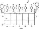
фиг.1 - вид сверху предпочтительного варианта выполнения настоящего изобретения;figure 1 is a top view of a preferred embodiment of the present invention;
фиг.2 - вид сбоку варианта выполнения по фиг.1;figure 2 is a side view of the embodiment of figure 1;
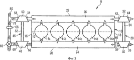
фиг.3 - вид сверху следующего предпочтительного варианта выполнения настоящего изобретения;figure 3 is a top view of a further preferred embodiment of the present invention;
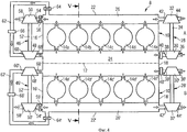
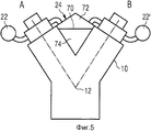
фиг.4 - вид сверху предпочтительного варианта выполнения V-образного двигателя;4 is a top view of a preferred embodiment of a V-shaped engine;
фиг.5 - разрез двигателя по линии V-V по фиг.4;5 is a section of the engine along the line V-V in figure 4;
фиг.6 - вид сверху варианта выполнения, модифицированного по сравнению с вариантом выполнения по фиг.1;6 is a top view of a variant of execution, modified in comparison with the embodiment of figure 1;
фиг.7 - вид сбоку варианта выполнения, модифицированного по сравнению с вариантом выполнения по фиг.2;Fig.7 is a side view of a variant of execution, modified in comparison with the embodiment of Fig.2;
фиг.8 - разрез модифицированного двигателя по фиг.5.Fig.8 is a sectional view of the modified engine of Fig.5.
На всех фигурах соответствующие элементы обозначены одинаковыми ссылочными позициями.In all figures, the corresponding elements are denoted by the same reference position.
Ниже со ссылкой на фиг.1 и 2 будет описан предпочтительный вариант выполнения двигателя внутреннего сгорания с турбонаддувом с рециркуляцией выхлопных газов. Двигатель 8 внутреннего сгорания, например однорядный 5-цилиндровый двигатель, может содержать картер 10, внутри которого установлен коленчатый вал 12. Коленчатый вал 12 обозначен двойной пунктирной линией. Коленчатый вал 12 соединен с поршнями (не показаны), которые перемещаются в соответствующих цилиндрах 14а-14е.A preferred embodiment of a turbocharged internal combustion engine with exhaust gas recirculation will be described below with reference to FIGS. 1 and 2. The
Показанный двигатель 8 имеет торцевые стороны 16, 18, противолежащие в продольном направлении коленчатого вала 12, и боковые стороны 20, 22, противолежащие в направлении, перпендикулярном продольному направлению коленчатого вала 12.The
Впускной коллектор 24 продолжается вдоль боковой стороны 20 двигателя и соединен с цилиндрами 14а-14е. Каждый из цилиндров 14а-14е может быть снабжен, по меньшей мере, одним впускным клапаном, который адаптирован для открывания или закрывания соединения между впускным коллектором 24 и рабочей камерой соответствующего цилиндра. С другой боковой стороны 22 может быть предусмотрен выпускной коллектор 26, который может быть соединен с каждым из цилиндров 14а-14е. Каждый из цилиндров 14а-14е может иметь, по меньшей мере, один выпускной клапан, предназначенный для открывания и закрывания соединения между рабочей камерой в соответствующем цилиндре 14а-14е и выпускным коллектором.The
У одной из торцевых сторон 16, 18, в показанном варианте выполнения у стороны 18, может быть установлен турбонагнетатель 28 приточного воздуха, содержащий компрессор 30 и турбину 32, соединенные валом 34.At one of the
Впуск 36 компрессора 30 соединен с наружной атмосферой. Выпуск 38 компрессора соединен с впускным коллектором 24, при этом между выпуском 38 и впускным коллектором 24 может быть установлен охладитель 40.The
Впуск 42 турбины 32 соединен с выпускным коллектором 26. Выпуск 44 турбины 32 соединен с выхлопной системой двигателя, которая содержит средства очистки выхлопных газов и глушения звукового выхлопа.The
На стороне 16 двигателя 8 расположен турбонагнетатель 46 выхлопных газов, содержащий компрессор 48 и турбину 50, соединенные валом 52 с возможностью вращения.On the
Впуск 54 турбины 50 соединен с выпускным коллектором 26, при этом между турбиной 50 и выпускным коллектором 26 может быть установлен первый управляющий клапан 56. Выпуск 58 турбины 50 соединен с выхлопной системой двигателя аналогично выпуску 44 турбины 32.The
Впуск 60 компрессора 48 турбонагнетателя 46 выхлопных газов соединен с выпускным коллектором вторым управляющим клапаном 64 через воздуховод 62, и в воздуховоде 62 может быть установлен охладитель 66. Выпуск 68 компрессора 48 соединен с впускным коллектором 24.The
Как показано на фиг.2, впускной коллектор 24, который может быть отлит за одно с картером 10, разделен в продольном направлении разделительной стенкой 70 на канал 72 приточного воздуха и канал 74 выхлопных газов. Канал 72 приточного воздуха закрыт у конца рядом со стороной 16 двигателя и соединен у конца рядом со стороной 18 двигателя с выпуском 38 компрессора 30. Канал 74 выхлопных газов закрыт у конца рядом со стороной 18 двигателя и соединен с компрессором 48 турбонагнетателя 46 выхлопных газов у стороны рядом со стороной 16 двигателя. Предпочтительно, канал 72 приточного воздуха расположен над каналом 74 выхлопных газов. Канал 72 приточного воздуха соединен непосредственно с цилиндрами 14а-14е, в то время как канал 74 выхлопных газов сообщается с каналом 72 приточного воздуха через дроссельные отверстия 76, выполненные в разделительной стенке 70. Предпочтительно, по меньшей мере, одно из дроссельных отверстий 76 находится в положении, соответствующем положению одного из цилиндров 14а-14е.As shown in FIG. 2, the
На фиг.3 показан второй предпочтительный вариант выполнения двигателя внутреннего сгорания с турбонаддувом, в котором система воздуховодов турбонагнетателя 46 выхлопных газов была модифицирована по сравнению с вариантом выполнения по фиг.1. Ниже приводится описание только тех частей по фиг.3, которые добавлены по сравнению с вариантом выполнения по фиг.1FIG. 3 shows a second preferred embodiment of a turbocharged internal combustion engine in which the duct system of the
В соединении между выпускным коллектором 26 и впуском 54 турбины 50 турбонагнетателя 46 выхлопных газов не установлено никаких управляющих клапанов. Кроме того, выпуск 58 турбины 50 соединен с воздуховодом 78, который у одного конца 80 соединен с выхлопной системой двигателя и у другого конца соединен с управляющим клапаном 82, с помощью которого воздуховод 78 может быть соединен с впуском 60 компрессора 48 турбонагнетателя 46 выхлопных газов или с наружной атмосферой. Между соединением воздуховода 78 с турбиной 50 и клапаном 82 предусмотрен охладитель 66.No control valves are installed in the connection between the
На фиг.4 показан V-образный двигатель, содержащий два ряда цилиндров, А и В, соответствующих ряду цилиндров по фиг.1, но расположенных зеркально относительно вертикальной центральной плоскости двигателя, включая сюда коленчатый вал 12.Figure 4 shows a V-shaped engine containing two rows of cylinders, A and B, corresponding to the row of cylinders of figure 1, but located mirrored relative to the vertical central plane of the engine, including the
Как лучше показано на фиг.5, на которой представлен вид двигателя в разрезе по линии V-V из фиг.4, впускной коллектор 24 расположен между рядами А и В цилиндров. Канал 72 приточного воздуха соединен с компрессорами 30, 30' турбонагнетателей 28, 28' приточного воздуха, в то время как выпуски 68, 68' обоих турбонагнетателей выхлопных газов соединены с каналов 74 выхлопных газов.As best shown in FIG. 5, which shows a sectional view of the engine along line V-V of FIG. 4, the
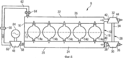
На фиг.6 показан вариант выполнения настоящего изобретения, модифицированный по сравнению с вариантом выполнения по фиг.1. Ниже приводится только описание модификаций по сравнению с фиг.1.Figure 6 shows an embodiment of the present invention, modified in comparison with the embodiment of figure 1. Below is only a description of the modifications in comparison with figure 1.
Согласно фиг.1 компрессор 48, который образует турбонагнетатель выхлопных газов, приводимый в действие турбиной 50 турбонагнетателя 46 выхлопных газов, приводится в действие электродвигателем 84, который управляется электронным блоком управления (не показан), так что компрессор 48, который образует турбонагнетатель, подает выхлопной газ в канал 74 выхлопного газа со скоростью и при давлении согласно рабочему состоянию двигателя 8 внутреннего сгорания, т.е. согласно нагрузке и частоте вращения двигателя. Поскольку электродвигатель 84 может управляться непосредственно в зависимости от рабочего состояния двигателя, второй управляющий клапан 64 можно не устанавливать.1, a
Вариант выполнения по фиг.6 мог бы быть также применен в варианте выполнения по фиг.4, при этом оба компрессора 48, 48' варианта выполнения по фиг.4 могли бы приводиться в движение соответствующими электродвигателями или общим электродвигателем.The embodiment of FIG. 6 could also be applied to the embodiment of FIG. 4, wherein both
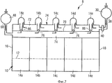
На фиг.7 показан вариант выполнения настоящего изобретения, модифицированного по сравнению с вариантом выполнения по фиг.2. Ниже приводится только описание модификаций.Figure 7 shows an embodiment of the present invention, modified in comparison with the embodiment of figure 2. The following is only a description of the modifications.
В то время как в варианте выполнения по фиг.2 дроссельные отверстия 76, которые соединяют внутреннюю сторону канала 74 выхлопных газов с внутренней стороной канала 72 приточного воздуха, образованы как простые отверстия в разделительной стенке 70, в варианте выполнения по фиг.7 эти дроссельные отверстия 76 образованы внутренними каналами трубок 86, которые продолжаются от разделительной стенки 70 в верхнем направлении. Предпочтительно, эти трубки 86 образованы так, что их свободные концы (концы, которые находятся на расстоянии от канала выхлопных газов) ведут непосредственно в воздуховоды, которые соединяют цилиндры 14а-14е с каналом 72 приточного воздуха, так что выхлопной газ из канала 74 выхлопного газа протекает в потоке приточного воздуха из канала 72 приточного воздуха в соответствующий цилиндр. С помощью трубок 86 обеспечивается, что любые капли в выхлопных газах, которые могут конденсироваться из выхлопных газов за счет уменьшения температуры выхлопных газов, непосредственно переносятся в цилиндры без конденсации на внутренней поверхности канала 72 приточного воздуха.While in the embodiment of FIG. 2,
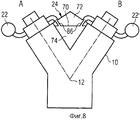
На фиг.8 представлен вид, аналогичный виду на фиг.5, и показано, как трубки 86, описанные выше, расположены в V-образном двигателе с двумя рядами А и В цилиндров.On Fig presents a view similar to the view in figure 5, and shows how the
Согласно фиг.1 двигатель, который может использоваться, например, в качестве приводного двигателя на тяжелых грузовиках, работает следующим образом.According to figure 1, an engine that can be used, for example, as a drive engine on heavy trucks, operates as follows.
При работающем двигателе турбина 32 турбонагнетателя 28 приточного воздуха и турбина 50 турбонагнетателя 46 выхлопных газов приводятся в действие выхлопными газами, выходящими с обоих концов выпускного коллектора 26. Турбина 32 приводит в действие компрессор 30, так чтобы сжатый приточный воздух, охлаждаемый в охладителе 40, протекал во впускной коллектор 24.With the engine running, the
Турбина 50 турбонагнетателя 46 выхлопных газов приводит в действие компрессор 48, в результате чего выхлопные газы, выходящие из выпускного коллектора 26 и охлаждаемые в охладителе 66, сжимаются компрессором 48 до давления, аналогичного или немного превышающего давление приточного воздуха в канале 72 приточного воздуха, так что сжатые выхлопные газы протекают через дроссельные отверстия 76 в канал 72 приточного воздуха, где они смешиваются со сжатым приточным воздухом. Смесь сжатого приточного воздуха и сжатого выхлопного газа протекает в рабочие камеры цилиндров.The
Скорость выхлопных газов, рециркулируемых в канале выпускных газов, может управляться управляющими клапанами 56 и 64, при этом управляющий клапан 56 будет управлять приводной мощностью турбины 50, а управляющий клапан 64 будет управлять полезным поперечным сечением воздуховода 62.The speed of the exhaust gases recirculated in the exhaust gas channel can be controlled by
Управляющие клапаны 64 и 56 управляются с помощью управляющих средств двигателя согласно рабочим параметрам двигателя, например согласно нагрузке, частоте вращения и температуре.The
Установка турбонагнетателей с противоположных сторон двигателя упрощает монтаж и позволяет эффективно использовать пространство. Кроме того, благодаря компактной конструкции потери потока сводятся к минимуму.Installing turbochargers on opposite sides of the engine simplifies installation and allows efficient use of space. In addition, due to the compact design, flow losses are minimized.
Благодаря конструкции впускного коллектора 24, разделенного с помощью разделительной стенки 70 на канал 72 приточного воздуха и канал 74 выхлопных газов, обеспечивается компактность и эффективность конструкции. Дроссельные отверстия 76, соединяющие канал 72 приточного воздуха и канал 74 выхлопных газов, позволяют получить эффективную смесь рециркулируемых выхлопных газов и приточного воздуха.Due to the design of the
Охладители 40 и 66, которые могут быть теплообменниками и отводят тепло от двигателя с помощью охлаждающей воды, увеличивают общий кпд.
Два управляющих клапана 56 и 64, обеспечивают эффективное управление скоростью рециркуляции выхлопных газов.Two
Расчетные параметры турбонагнетателя 46 выхлопных газов и турбонагнетателя 28 приточного воздуха устанавливаются таким образом, чтобы они удовлетворяли функциональным требованиям к двигателю в отношении скорости рециркуляции выхлопных газов в зависимости от рабочих параметров двигателя.The design parameters of the
Описанная базовая конструкция двигателя может быть модифицирована с учетом применения в различных двигателях. Конструкция может использоваться в двигателях, работающих по циклу Отто, дизельных двигателях, двигателях, работающих на жидком или газообразном топливе, и двигателях с различным числом цилиндров. Кроме того, впускной коллектор 24 не ограничивается до элемента, объединенного с картером 10, а может быть отдельным элементом, смонтированным на корпусе двигателя. Любой из охладителей 40 или 66 может не устанавливаться. Место установки управляющих клапанов может быть изменено. Воздуховод может быть соединен с выпуском 58 турбины 50.The described basic engine design can be modified to suit the application in various engines. The design can be used in Otto-cycle engines, diesel engines, liquid or gaseous fuel engines, and engines with different numbers of cylinders. In addition, the
Канал 64 выхлопных газов не ограничивается до расположения под каналом 72 приточного воздуха.The
Вариант выполнения по фиг.3 имеет отличия от варианта выполнения по фиг.1 в соединениях выпуска 58 турбины 50 и впуска 60 компрессора турбонагнетателя выхлопных газов. В состоянии клапана 82, в котором воздуховод 78 соединен с впуском 60 компрессора 48, выхлопные газы сжимаются в компрессоре 48 и подаются в выпускной коллектор 26 (фиг.2). Следует учесть, что воздуховод 78 мог бы быть соединен непосредственно с выпускным коллектором 26, как в варианте выполнения по фиг.1.The embodiment of FIG. 3 is different from the embodiment of FIG. 1 in the connections of the
Когда клапан 82 переключен в состояние, в котором воздуховод 78 отделен от впуска 60 и впуск 60 соединен с наружной атмосферой, турбонагнетатель 46 выхлопных газов действует как дополнительный турбонагнетатель приточного воздуха, аналогично турбонагнетателю 28 приточного воздуха. На этой стадии не происходит никакой рециркуляции выхлопных газов и осуществляется эффективный турбонаддув двигателя. Клапан 82 может быть пропорциональным клапаном, который обеспечивает управление скоростью рециркуляции выхлопных газов между максимальным значением (впуск 60 соединен только с воздуховодом 78) и минимальным значением (впуск 60 полностью отделен от воздуховода 78). Существует много применений, в которых полезно эксплуатировать двигатель с рециркуляцией выхлопных газов или без такой рециркуляции. Закрывание впуска 54 турбины 50 привело бы к увеличению давления выхлопных газов в выпускном коллекторе 26, что стало бы причиной перегрузки турбонагнетателя 28 приточного воздуха. Переключение турбонагнетателя 46 выхлопных газов со сжатия выхлопных газов на сжатие приточного воздуха позволяет решить эту проблему.When the
Вариант выполнения, представленный на фиг.4 соответствует варианту выполнения по фиг.1, но применяется для двигателя V6. Использование общего впускного коллектора 24 для рядов А и В цилиндров обеспечивает компактную конструкцию с короткими воздуховодами и низкими потерями потока. Конструкция турбонагнетателя выхлопных газов по фиг.3 также могла бы быть применена для фиг.4. Кроме того, турбины 48 и 48' турбонагнетателей 46 и 46' выхлопных газов могли бы быть объединены в один компрессор, приводимый в действие двумя турбинами 50, 50'. Вместо двух турбин 50, 50' может быть предусмотрена только одна турбина, и впуск этой турбины может быть соединен с выпускными коллекторами 26 и 26'. Кроме того, вместо компрессоров 30 и 30' может быть использован только один компрессор, и вместо обеих турбин 32 и 32' может быть использована только одна турбина. Компоновка турбонагнетателя 46 выхлопных газов по фиг.3, которая позволяет переключать турбонагнетатель выхлопных газов с рециркуляции выхлопных газов на сжатие приточного воздуха, может быть использована также с двигателем, который не оборудован впускным коллектором и разделен разделительной перегородкой на два канала. Выхлопные газы, сжимаемые компрессором 48, или приточный воздух, сжимаемый компрессором 48, может подаваться непосредственно во впускной коллектор двигателя или воздуховод, соединенный с выпускным коллектором.The embodiment shown in FIG. 4 corresponds to the embodiment of FIG. 1, but is applied to the V6 engine. The use of a
Выше со ссылкой на фиг.1-5 была описана работа двигателя по различным вариантам выполнения. Замена турбины 50 турбонагнетателя 46 выхлопного газа электродвигателем 84 по фиг.6 позволяет за счет управления частотой вращения электродвигателя 84 сжимать или нагнетать выхлопные газы, подаваемые в канал 74 выхлопных газов, и/или приточный воздух, подаваемый в канал 74 выхлопных газов согласно варианту по фиг.3. Кроме того, использование электродвигателя 84 вместо турбины 50 позволяет увеличить наддув двигателя компрессором 30, поскольку все выхлопные газы могут быть использованы для приведения в действие турбины 32 турбонагнетателя 28 приточного воздуха. Использование трубок 86 по фиг.7 или 8 исключает риск того, что капли, конденсируемые в результате уменьшения температуры рециклированных выхлопных газов, могут осаждаться на внутренней поверхности канала 72 приточного воздуха.Above with reference to FIGS. 1-5, engine operation in various embodiments has been described. Replacing a
Эффективный поток через поперечные сечения для выхлопных газов, вытекающих из канала 74 выхлопных газов в цилиндры 14а-14е через дроссельные отверстия 76 или трубки 86, и для приточного воздуха, протекающего из канала 72 приточного воздуха в цилиндры 14а-14е, может быть непостоянным по длине коллектора 24. Он может быть модифицирован, например, за счет количества дроссельных отверстий 76 и/или поперечного сечения дроссельных отверстий 76 или трубок 86, соответствующих различным цилиндрам, так чтобы обеспечить подачу во все цилиндры одинакового количества смеси приточного воздуха и выхлопных газов, имеющей одинаковое соотношение приточного воздуха и выхлопных газов.The effective flow through the cross sections for exhaust gases flowing from the
Несмотря на то что здесь были описаны предпочтительные варианты выполнения этого изобретения, могут быть внедрены усовершенствования и модификации без отклонения от объема приведенной ниже формулы изобретения.Although preferred embodiments of this invention have been described herein, improvements and modifications may be made without departing from the scope of the claims below.
Claims (17)
множество цилиндров (14а-14е), каждый из которых имеет, по меньшей мере, одно впускное отверстие и, по меньшей мере, одно выпускное отверстие,
впускной коллектор (24), соединенный с указанными впускными отверстиями,
выпускной коллектор (26), соединенный с указанными выпускными отверстиями,
турбонагнетатель (28) приточного воздуха, имеющий турбину (32), впуск (42) которой соединен с выпускным коллектором (26) и выпуск (44) которой соединен с атмосферой, и компрессор (30) приточного воздуха, впуск (36) которого соединен с атмосферой и выпуск (38) которого соединен с впускным коллектором (24), и
турбонагнетатель (46) выхлопных газов, имеющий компрессор (48), впуск которого предназначен для подачи к нему выхлопных газов из выпускного коллектора и выпуск которого соединен с впускным коллектором (24),
при этом впускной коллектор (24) разделен разделительной стенкой (70) на канал (72) приточного воздуха и канал (74) выхлопных газов, и один из этих каналов (72, 74) соединен с впускными отверстиями цилиндров (14а-14е),
причем канал (72) приточного воздуха соединен с выпуском (38) компрессора (30) турбонагнетателя (28) приточного воздуха,
при этом канал выхлопных газов соединен с выпуском (68) компрессора (48) турбонагнетателя (46), а разделительная стенка (70) имеет дроссельные отверстия (76), соединяющие два канала (72, 74).1. An internal combustion engine with turbocharging and exhaust gas recirculation, containing:
a plurality of cylinders (14a-14e), each of which has at least one inlet and at least one outlet,
an intake manifold (24) connected to said inlet openings,
an exhaust manifold (26) connected to said outlet openings,
a supply air turbocharger (28) having a turbine (32), the inlet (42) of which is connected to the exhaust manifold (26) and the outlet (44) of which is connected to the atmosphere, and the supply air compressor (30), the inlet (36) of which is connected to atmosphere and an outlet (38) which is connected to the intake manifold (24), and
an exhaust turbocharger (46) having a compressor (48), the inlet of which is intended to supply exhaust gases to it from the exhaust manifold and the outlet of which is connected to the intake manifold (24),
wherein the intake manifold (24) is divided by a partition wall (70) into the supply air channel (72) and the exhaust gas channel (74), and one of these channels (72, 74) is connected to the cylinder inlets (14a-14e),
moreover, the supply air channel (72) is connected to the outlet (38) of the compressor (30) of the supply air turbocharger (28),
the exhaust gas channel is connected to the outlet (68) of the compressor (48) of the turbocharger (46), and the dividing wall (70) has throttle openings (76) connecting the two channels (72, 74).
компрессора (48) нагнетателя выхлопных газов выполнен с возможностью выборочного соединения с воздуховодом (62, 58), в который подаются выхлопные газы, или с атмосферой.6. The engine according to any one of claims 1 to 4, in which the valve (82) is installed in front of the inlet (60) of the compressor (48) of the exhaust turbocharger (46), while the inlet
the compressor (48) of the exhaust gas blower is configured to selectively connect to an air duct (62, 58) into which exhaust gases are supplied, or to the atmosphere.
множество цилиндров (14а-14е), каждый из которых имеет, по меньшей мере, одно впускное отверстие и одно выпускное отверстие,
впускной коллектор (24), соединенный с указанными впускными отверстиями,
выпускной коллектор (26), соединенный с указанными выпускными отверстиями,
турбонагнетатель (28) приточного воздуха с турбиной (32), впуск (42) которой соединен с выпускным коллектором и выпуск (44) которой соединен с атмосферой, и компрессор (30), впуск (36) которого соединен с атмосферой и выпуск (38) которого соединен с впускным коллектором (24), и
турбонагнетатель (46) выхлопных газов с компрессором (48), выпуск (68) которого соединен с впускным коллектором,
в котором впуск компрессора (48) турбонагнетателя (46) выхлопных газов выполнен с возможностью выборочного соединения с выпускным коллектором или с атмосферой.16. An internal combustion engine with a turbocharger and exhaust gas recirculation, containing:
a plurality of cylinders (14a-14e), each of which has at least one inlet and one outlet,
an intake manifold (24) connected to said inlet openings,
an exhaust manifold (26) connected to said outlet openings,
a supply air turbocharger (28) with a turbine (32), the inlet (42) of which is connected to the exhaust manifold and the outlet (44) of which is connected to the atmosphere, and a compressor (30), whose inlet (36) is connected to the atmosphere and the outlet (38) which is connected to the intake manifold (24), and
exhaust turbocharger (46) with a compressor (48), the outlet (68) of which is connected to the intake manifold,
in which the inlet of the compressor (48) of the exhaust turbocharger (46) is selectively connected to the exhaust manifold or to the atmosphere.
Applications Claiming Priority (3)
| Application Number | Priority Date | Filing Date | Title |
|---|---|---|---|
| EP09002111.4 | 2009-02-16 | ||
| EP09002111A EP2218896B1 (en) | 2009-02-16 | 2009-02-16 | A turbocharged engine with exhaust gas recycling |
| PCT/EP2010/000924 WO2010091891A2 (en) | 2009-02-16 | 2010-02-15 | A turbocharged engine with exhaust gas recycling |
Publications (2)
| Publication Number | Publication Date |
|---|---|
| RU2011138030A RU2011138030A (en) | 2013-03-27 |
| RU2541084C2 true RU2541084C2 (en) | 2015-02-10 |
Family
ID=40848500
Family Applications (1)
| Application Number | Title | Priority Date | Filing Date |
|---|---|---|---|
| RU2011138030/06A RU2541084C2 (en) | 2009-02-16 | 2010-02-15 | Turbo-supercharged engine with recirculation of exhaust gases |
Country Status (8)
| Country | Link |
|---|---|
| US (1) | US8919121B2 (en) |
| EP (1) | EP2218896B1 (en) |
| KR (1) | KR101650603B1 (en) |
| CN (1) | CN102317611B (en) |
| AT (1) | ATE552417T1 (en) |
| BR (1) | BRPI1006686A2 (en) |
| RU (1) | RU2541084C2 (en) |
| WO (1) | WO2010091891A2 (en) |
Families Citing this family (11)
| Publication number | Priority date | Publication date | Assignee | Title |
|---|---|---|---|---|
| EP2415988A1 (en) | 2010-08-06 | 2012-02-08 | Caterpillar Motoren GmbH & Co. KG | Two-stage turbocharged engine |
| FR2965306B1 (en) * | 2010-09-27 | 2012-09-14 | Valeo Systemes Thermiques | DEVICE FOR MIXING A RECIRCULATED INTAKE GAS FLOW AND A RECIRCULATED EXHAUST GAS FLOW COMPRISING RECIRCULATED EXHAUST GAS FLOW ISOLATION MEANS |
| US9587596B2 (en) * | 2012-02-13 | 2017-03-07 | Ford Global Technologies, Llc | Asymmetric exhaust gas recirculation system |
| GB2500193B (en) * | 2012-03-12 | 2014-06-25 | Jaguar Land Rover Ltd | Combined Turbocharger and EGR Pump Assembly |
| EP2647806A1 (en) | 2012-04-05 | 2013-10-09 | Caterpillar Motoren GmbH & Co. KG | Charge air guide element for internal combustion engine |
| US9038383B2 (en) | 2012-07-24 | 2015-05-26 | Caterpillar Inc. | Flywheel assembly for a turbocharger |
| US9163586B2 (en) * | 2013-01-31 | 2015-10-20 | Electro-Motive Diesel, Inc. | Exhaust system having parallel EGR coolers |
| US9441531B2 (en) | 2014-01-02 | 2016-09-13 | Caterpillar Inc. | Diverter valve for charge air system |
| CN111492128B (en) * | 2017-12-20 | 2022-10-25 | 沃尔沃卡车集团 | Sealing gasket for sealing the connection between an exhaust manifold and a turbine |
| US11421611B2 (en) * | 2018-06-29 | 2022-08-23 | Volvo Truck Corporation | Internal combustion engine |
| CN108894872B (en) * | 2018-09-04 | 2024-04-12 | 康跃科技(山东)有限公司 | In-line multi-cylinder engine and sequential supercharging exhaust system thereof |
Citations (6)
| Publication number | Priority date | Publication date | Assignee | Title |
|---|---|---|---|---|
| US4693226A (en) * | 1986-06-02 | 1987-09-15 | Ford Motor Company | EGR control system |
| EP0523029A2 (en) * | 1991-07-10 | 1993-01-13 | Ab Volvo | A device at intake systems for internal combustion engines |
| DE4436732A1 (en) * | 1994-10-14 | 1996-04-18 | Abb Management Ag | Method and device for high-pressure exhaust gas recirculation of a supercharged internal combustion engine |
| DE19603591C1 (en) * | 1996-02-01 | 1997-03-06 | Daimler Benz Ag | Exhaust gas feedback system for turbocharged internal combustion engines |
| RU2230212C2 (en) * | 1998-11-09 | 2004-06-10 | Стт Эмтек Актиеболаг | Method of, device for and valve for exhaust gas recirculation system and c ontrol method and device |
| DE102008014168A1 (en) * | 2007-03-23 | 2008-09-25 | Behr Gmbh & Co. Kg | Charge fluid intake module and internal combustion engine |
Family Cites Families (17)
| Publication number | Priority date | Publication date | Assignee | Title |
|---|---|---|---|---|
| JPH08144868A (en) * | 1994-11-17 | 1996-06-04 | Toyota Motor Corp | Exhaust gas recirculation system for internal combustion engine |
| JP3809696B2 (en) * | 1997-03-25 | 2006-08-16 | 株式会社豊田自動織機 | Exhaust gas recirculation device for internal combustion engine |
| US6062026A (en) * | 1997-05-30 | 2000-05-16 | Turbodyne Systems, Inc. | Turbocharging systems for internal combustion engines |
| US6138649A (en) * | 1997-09-22 | 2000-10-31 | Southwest Research Institute | Fast acting exhaust gas recirculation system |
| JP3998861B2 (en) * | 1999-06-16 | 2007-10-31 | 株式会社小松製作所 | Exhaust gas recirculation device and control method thereof |
| IT1319919B1 (en) * | 2000-02-25 | 2003-11-12 | Iveco Fiat | INTAKE MANIFOLD FOR AN ENDOTHERMAL ENGINE. |
| JP4207695B2 (en) * | 2003-07-02 | 2009-01-14 | マツダ株式会社 | EGR control device for engine |
| DE10354129A1 (en) * | 2003-11-19 | 2005-06-23 | Mahle Filtersysteme Gmbh | Intake system for an internal combustion engine |
| FR2879235B1 (en) * | 2004-12-15 | 2007-03-02 | Renault Sas | INTERNAL COMBUSTION ENGINE WITH RECIRCULATION OF EXHAUST GASES AND EXHAUST AIR INJECTION |
| KR20070046570A (en) * | 2005-10-31 | 2007-05-03 | 현대자동차주식회사 | Intake manifold for internal combustion engine |
| US7571608B2 (en) * | 2005-11-28 | 2009-08-11 | General Electric Company | Turbocharged engine system and method of operation |
| FR2895461B1 (en) * | 2005-12-22 | 2008-01-25 | Renault Sas | DEVICE FOR INJECTING WATER AND RECIRCULATED GASES |
| US8297054B2 (en) * | 2008-10-31 | 2012-10-30 | Caterpillar Inc. | Exhaust system having turbo-assisted high-pressure EGR |
| CN102165164B (en) * | 2008-12-17 | 2014-02-26 | 爱信精机株式会社 | Air intake manifold |
| US8640457B2 (en) * | 2009-10-13 | 2014-02-04 | General Electric Company | System and method for operating a turbocharged engine |
| EP2599989B1 (en) * | 2010-07-30 | 2015-01-07 | Honda Motor Co., Ltd. | Air-intake device |
| JP5948883B2 (en) * | 2012-01-17 | 2016-07-06 | マツダ株式会社 | Engine intake system |
-
2009
- 2009-02-16 AT AT09002111T patent/ATE552417T1/en active
- 2009-02-16 EP EP09002111A patent/EP2218896B1/en not_active Not-in-force
-
2010
- 2010-02-15 BR BRPI1006686A patent/BRPI1006686A2/en not_active IP Right Cessation
- 2010-02-15 US US13/201,657 patent/US8919121B2/en not_active Expired - Fee Related
- 2010-02-15 WO PCT/EP2010/000924 patent/WO2010091891A2/en active Application Filing
- 2010-02-15 RU RU2011138030/06A patent/RU2541084C2/en not_active IP Right Cessation
- 2010-02-15 CN CN201080007898.5A patent/CN102317611B/en not_active Expired - Fee Related
- 2010-02-15 KR KR1020117018855A patent/KR101650603B1/en active IP Right Grant
Patent Citations (6)
| Publication number | Priority date | Publication date | Assignee | Title |
|---|---|---|---|---|
| US4693226A (en) * | 1986-06-02 | 1987-09-15 | Ford Motor Company | EGR control system |
| EP0523029A2 (en) * | 1991-07-10 | 1993-01-13 | Ab Volvo | A device at intake systems for internal combustion engines |
| DE4436732A1 (en) * | 1994-10-14 | 1996-04-18 | Abb Management Ag | Method and device for high-pressure exhaust gas recirculation of a supercharged internal combustion engine |
| DE19603591C1 (en) * | 1996-02-01 | 1997-03-06 | Daimler Benz Ag | Exhaust gas feedback system for turbocharged internal combustion engines |
| RU2230212C2 (en) * | 1998-11-09 | 2004-06-10 | Стт Эмтек Актиеболаг | Method of, device for and valve for exhaust gas recirculation system and c ontrol method and device |
| DE102008014168A1 (en) * | 2007-03-23 | 2008-09-25 | Behr Gmbh & Co. Kg | Charge fluid intake module and internal combustion engine |
Also Published As
| Publication number | Publication date |
|---|---|
| KR20110118670A (en) | 2011-10-31 |
| CN102317611A (en) | 2012-01-11 |
| KR101650603B1 (en) | 2016-08-23 |
| EP2218896A1 (en) | 2010-08-18 |
| US8919121B2 (en) | 2014-12-30 |
| WO2010091891A2 (en) | 2010-08-19 |
| WO2010091891A3 (en) | 2010-12-02 |
| EP2218896B1 (en) | 2012-04-04 |
| BRPI1006686A2 (en) | 2016-04-12 |
| CN102317611B (en) | 2014-11-26 |
| US20110302919A1 (en) | 2011-12-15 |
| RU2011138030A (en) | 2013-03-27 |
| ATE552417T1 (en) | 2012-04-15 |
Similar Documents
| Publication | Publication Date | Title |
|---|---|---|
| RU2541084C2 (en) | Turbo-supercharged engine with recirculation of exhaust gases | |
| CN101743390B (en) | Internal combustion engine | |
| RU2065526C1 (en) | Sucking plant for internal combustion engine | |
| US3881455A (en) | Aftercooler for internal combustion engine | |
| JP4496248B2 (en) | Supercharged engine with EGR device | |
| US4932368A (en) | Suction arrangement for internal combustion engine | |
| KR20120116474A (en) | Directly communicated turbocharger | |
| EP3438433B1 (en) | Engine device | |
| US7343907B2 (en) | Crankcase lower part | |
| JP6157466B2 (en) | Internal combustion engine for automobile | |
| KR102498650B1 (en) | Engine device | |
| EP2148061B1 (en) | A two-stage turbocharged combustion engine | |
| US10190482B2 (en) | Air inlet assembly for an internal combustion engine | |
| US20040173343A1 (en) | Heat exchange assembly | |
| JP6376151B2 (en) | Engine intake cooling system | |
| US20210215090A1 (en) | Charge Air Cooling Unit for a Two-Staged Turbocharger | |
| US20190226422A1 (en) | Multi-cylinder engine | |
| EP3670859A1 (en) | Engine provided with mechanical supercharger | |
| KR20190057654A (en) | Intake systme for internal combustion engine | |
| JP7196629B2 (en) | Blow-by gas system for supercharged engines | |
| JP7192256B2 (en) | Blow-by gas system for supercharged engines | |
| JP6344404B2 (en) | Engine intake cooling system | |
| GB2502806A (en) | Intercooler arrangement for a vehicle engine having a turbocharger and a supercharger | |
| JPS62135610A (en) | Cooling device for supercharged engine | |
| ITUB20155457A1 (en) | INTERNAL COMBUSTION ENGINE AND METHOD OF CONTROL OF THE SAME ENGINE |
Legal Events
| Date | Code | Title | Description |
|---|---|---|---|
| MM4A | The patent is invalid due to non-payment of fees |
Effective date: 20160216 |