RU2538305C2 - Image processing device, method and programme - Google Patents
Image processing device, method and programme Download PDFInfo
- Publication number
- RU2538305C2 RU2538305C2 RU2011134145/08A RU2011134145A RU2538305C2 RU 2538305 C2 RU2538305 C2 RU 2538305C2 RU 2011134145/08 A RU2011134145/08 A RU 2011134145/08A RU 2011134145 A RU2011134145 A RU 2011134145A RU 2538305 C2 RU2538305 C2 RU 2538305C2
- Authority
- RU
- Russia
- Prior art keywords
- symmetry
- degree
- input image
- edge
- module
- Prior art date
Links
Images


Classifications
-
- H—ELECTRICITY
- H04—ELECTRIC COMMUNICATION TECHNIQUE
- H04N—PICTORIAL COMMUNICATION, e.g. TELEVISION
- H04N5/00—Details of television systems
- H04N5/14—Picture signal circuitry for video frequency region
- H04N5/142—Edging; Contouring
-
- G—PHYSICS
- G06—COMPUTING; CALCULATING OR COUNTING
- G06T—IMAGE DATA PROCESSING OR GENERATION, IN GENERAL
- G06T7/00—Image analysis
- G06T7/60—Analysis of geometric attributes
- G06T7/68—Analysis of geometric attributes of symmetry
-
- G—PHYSICS
- G06—COMPUTING; CALCULATING OR COUNTING
- G06V—IMAGE OR VIDEO RECOGNITION OR UNDERSTANDING
- G06V10/00—Arrangements for image or video recognition or understanding
- G06V10/40—Extraction of image or video features
- G06V10/42—Global feature extraction by analysis of the whole pattern, e.g. using frequency domain transformations or autocorrelation
-
- G—PHYSICS
- G06—COMPUTING; CALCULATING OR COUNTING
- G06V—IMAGE OR VIDEO RECOGNITION OR UNDERSTANDING
- G06V20/00—Scenes; Scene-specific elements
-
- H—ELECTRICITY
- H04—ELECTRIC COMMUNICATION TECHNIQUE
- H04N—PICTORIAL COMMUNICATION, e.g. TELEVISION
- H04N23/00—Cameras or camera modules comprising electronic image sensors; Control thereof
-
- H—ELECTRICITY
- H04—ELECTRIC COMMUNICATION TECHNIQUE
- H04N—PICTORIAL COMMUNICATION, e.g. TELEVISION
- H04N23/00—Cameras or camera modules comprising electronic image sensors; Control thereof
- H04N23/60—Control of cameras or camera modules
- H04N23/64—Computer-aided capture of images, e.g. transfer from script file into camera, check of taken image quality, advice or proposal for image composition or decision on when to take image
-
- G—PHYSICS
- G06—COMPUTING; CALCULATING OR COUNTING
- G06T—IMAGE DATA PROCESSING OR GENERATION, IN GENERAL
- G06T2207/00—Indexing scheme for image analysis or image enhancement
- G06T2207/10—Image acquisition modality
- G06T2207/10024—Color image
Landscapes
- Engineering & Computer Science (AREA)
- Multimedia (AREA)
- Physics & Mathematics (AREA)
- Signal Processing (AREA)
- General Physics & Mathematics (AREA)
- Theoretical Computer Science (AREA)
- Computer Vision & Pattern Recognition (AREA)
- Geometry (AREA)
- Image Analysis (AREA)
- Image Processing (AREA)
- Indication In Cameras, And Counting Of Exposures (AREA)
- Studio Devices (AREA)
Abstract
Description
Область техники, к которой относится изобретениеFIELD OF THE INVENTION
Настоящее изобретение относится к устройству обработки изображений и способу обработки изображений и программе, и, в частности, настоящее изобретение относится к устройству обработки изображений и к способу обработки изображений и программе, которые позволяют классифицировать композицию входного изображения.The present invention relates to an image processing apparatus and an image processing method and a program, and in particular, the present invention relates to an image processing apparatus and an image processing method and a program that classifies an input image composition.
Уровень техникиState of the art
В последние годы была разработана технология, позволяющая различать структуру композиции изображения, снимаемого устройством формирования изображения, таким как цифровая камера и т.п.In recent years, a technology has been developed to distinguish between the composition structure of an image captured by an image forming apparatus, such as a digital camera and the like.
Например, была разработана технология, которая распознает субъект внимания, распознает состояние субъекта внимания и выбирает структуру композиции, включающую в себя субъект внимания среди множества записанных структур композиции на основе распознанного состояния субъекта внимания. Например, пример такой технологии раскрыт в Публикации №2008-81246 находящейся на экспертизе заявки на японский патент.For example, a technology has been developed that recognizes the subject of attention, recognizes the state of the subject of attention, and selects the composition structure that includes the subject of attention among the many recorded structures of the composition based on the recognized state of the subject of attention. For example, an example of such a technology is disclosed in Publication No. 2008-81246 of the pending Japanese patent application.
Кроме того, было предложено устройство обработки изображений, которое детектирует характерную структуру путем анализа входного изображения, рассчитывает, как значение оценки, степень ассоциации между множеством предварительно подготовленных композиций и детектируемой характерной структурой и определяет композицию входного изображения на основе значения оценки. Например, пример такого устройства обработки изображений раскрыт в публикации №2009-159023 находящейся на экспертизе заявки на японский патент.In addition, an image processing apparatus has been proposed that detects a characteristic structure by analyzing an input image, calculates, as an evaluation value, the degree of association between a plurality of pre-prepared compositions and a detectable characteristic structure, and determines the composition of the input image based on the evaluation value. For example, an example of such an image processing device is disclosed in Japanese Patent Application Publication No. 2009-159023.
Кроме того, была предложена камера, которая выделяет кромку, соответствующую верхнему краю основного субъекта снятого изображения, или кромку, продолжающуюся между двумя соответствующими сторонами снятого изображения, сравнивает положение или степень наклона выделенной кромки с предварительно определенной соответствующей протяженностью, и определяет, является ли композиция правильной или неправильной. Например, пример такого устройства обработки изображений раскрыт в японском патенте №4029174.In addition, a camera has been proposed that highlights an edge corresponding to the upper edge of the main subject of the captured image, or an edge extending between the two respective sides of the captured image, compares the position or degree of inclination of the selected edge with a predetermined appropriate length, and determines whether the composition is correct or wrong. For example, an example of such an image processing device is disclosed in Japanese Patent No. 4029174.
Сущность изобретенияSUMMARY OF THE INVENTION
Однако в способе в соответствии с публикацией №2008-81246 находящейся на экспертизе заявки на японский патент требовалось выполнение дорогостоящих операций для распознавания субъекта или распознавания состояния субъекта внимания.However, in the method in accordance with publication No. 2008-81246 of the pending Japanese patent application, costly operations were required to recognize the subject or recognize the state of the subject of attention.
Кроме того, в способе в соответствии с публикацией №2009-159023 находящейся на экспертизе заявки на японский патент, поскольку оценочное значение между множеством предварительно подготовленных композиций и характерной структурой, детектируемой на основе анализа входного изображения, рассчитывают относительно каждого из пикселей, также требовалось выполнять дорогостоящую операцию.In addition, in the method in accordance with publication No. 2009-159023 of the pending Japanese patent application, since the estimated value between the plurality of pre-prepared compositions and the characteristic structure detected based on the analysis of the input image is calculated with respect to each of the pixels, it was also necessary to perform expensive operation.
Кроме того, в способе по японскому патенту №4029174, поскольку критерий решения, для определения, является ли композиция правильной или неправильной, основан только на кромке, соответствующей верхнему краю основного предмета в снятом изображении, или кромке, продолжающейся между двумя соответствующими сторонами снятого изображения, тип композиции, который может быть определен, был ограничен.In addition, in the method according to Japanese patent No. 4029174, since the decision criterion for determining whether the composition is correct or incorrect is based only on an edge corresponding to the upper edge of the main subject in the captured image, or an edge extending between two corresponding sides of the captured image, the type of composition that can be determined has been limited.
Настоящее изобретение направлено на решение описанных выше задач. Кроме того, желательно классифицировать композицию входного изображения на подробные структуры композиции, используя операции, выполняемые с более низкими затратами.The present invention is directed to solving the above problems. In addition, it is desirable to classify the composition of the input image into detailed structures of the composition using operations performed at lower cost.
В соответствии с этим, раскрыто устройство для обработки входного изображения. Устройство может включать в себя модуль расчета степени симметрии, который может быть выполнен с возможностью приема входного изображения и расчета степени симметрии входного изображения. Устройство также может включать в себя модуль детектирования линии разделения, который может быть выполнен с возможностью приема входного изображения и детектирования линии разделения, которая разделяет две стороны входного изображения. Кроме того, устройство может включать в себя модуль классификации, который может быть выполнен с возможностью классификации входного изображения на основе степени симметрии и линии разделения. Модуль классификации также может быть выполнен с возможностью генерировать сигнал классификации для обеспечения, по меньшей мере, одного из отображения или сохранения классификации.Accordingly, an apparatus for processing an input image is disclosed. The device may include a module for calculating the degree of symmetry, which can be configured to receive the input image and calculate the degree of symmetry of the input image. The device may also include a separation line detection module, which may be configured to receive an input image and detect a separation line that separates the two sides of the input image. In addition, the device may include a classification module, which may be configured to classify the input image based on the degree of symmetry and the separation line. The classification module may also be configured to generate a classification signal to provide at least one of the display or storage of the classification.
Здесь также раскрыт способ обработки входного изображения. Процессор может выполнять программу для обеспечения выполнения устройством способа. Программа может быть сохранена в энергонезависимом, считываемом компьютером носителе информации. Способ может включать в себя прием входного изображения. Кроме того, способ может включать в себя расчет степени симметрии входного изображения. Способ также может включать в себя детектирование линии разделения, которая разделяет две стороны входного изображения. Кроме того, способ может включать в себя классификацию входного изображения на основе степени симметрии и линии разделения. Способ также может включать в себя генерирование сигнала классификации для обеспечения, по меньшей мере, одного из отображения или сохранения классификации.A method for processing an input image is also disclosed herein. A processor may execute a program to enable the device to execute a method. The program may be stored in a non-volatile computer readable storage medium. The method may include receiving an input image. In addition, the method may include calculating the degree of symmetry of the input image. The method may also include detecting a separation line that separates the two sides of the input image. In addition, the method may include classifying the input image based on the degree of symmetry and the separation line. The method may also include generating a classification signal to provide at least one of the display or storage of the classification.
Краткое описание чертежейBrief Description of the Drawings
На фиг.1 показана блок-схема, иллюстрирующая пример функциональной конфигурации устройства обработки изображений в соответствии с вариантом осуществления раскрытой теперь технологии;1 is a block diagram illustrating an example of a functional configuration of an image processing apparatus in accordance with an embodiment of the technology now disclosed;
на фиг.2 показана блок-схема, иллюстрирующая пример функциональной конфигурации модуля расчета степени симметрии (то есть программного модуля, модуля аппаратных средств или комбинации программного модуля и модуля аппаратных средств);2 is a block diagram illustrating an example of a functional configuration of a symmetry calculation module (i.e., a software module, a hardware module, or a combination of a software module and a hardware module);
на фиг.3 показана блок-схема, иллюстрирующая пример функциональной конфигурации модуля расчета степени симметрии кромки;figure 3 shows a block diagram illustrating an example of a functional configuration of the module for calculating the degree of symmetry of the edge;
на фиг.4 показана блок-схема, иллюстрирующая пример функциональной конфигурации модуля расчета степени симметрии цвета;4 is a block diagram illustrating an example of a functional configuration of a module for calculating a degree of color symmetry;
на фиг.5 показана блок-схема, иллюстрирующая пример функциональной конфигурации модуля детектирования линии разделения;5 is a block diagram illustrating an example of a functional configuration of a separation line detection module;
на фиг.6 показана блок-схема, иллюстрирующая пример функциональной конфигурации горизонтального модуля детектирования линии разделения;6 is a block diagram illustrating an example of a functional configuration of a horizontal dividing line detection module;
на фиг.7 показана блок-схема, иллюстрирующая пример функциональной конфигурации модуля детектирования вертикальной линии разделения;7 is a block diagram illustrating an example of a functional configuration of a module for detecting a vertical separation line;
на фиг.8 показана блок-схема, иллюстрирующая пример функциональной конфигурации наклонного модуля детектирования линии разделения;Fig. 8 is a block diagram illustrating an example of a functional configuration of an oblique dividing line detection module;
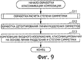
на фиг.9 показана блок-схема последовательности операций, поясняющая обработку классификации композиции;9 is a flowchart for explaining composition classification processing;
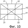
на фиг.10 показана схема, поясняющая структуру композиции, обычно рекомендуемую для фотоснимка и т.п.;figure 10 shows a diagram explaining the structure of the composition, usually recommended for a photograph, etc .;
на фиг.11 показана блок-схема последовательности операций, поясняющая обработку вычисления степени симметрии;11 is a flowchart for explaining a process for calculating a degree of symmetry;
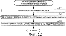
на фиг.12 показана блок-схема последовательности операций, поясняющая обработку вычисления степени симметрии кромки;12 is a flowchart for explaining processing for calculating an edge symmetry degree;
на фиг.13 показана схема, поясняющая входное изображение и изображение кромки;13 is a diagram for explaining an input image and an edge image;
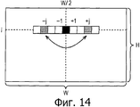
на фиг.14 показана схема, поясняющая пример вычисления степени симметрии кромки слева направо;on Fig shows a diagram illustrating an example of calculating the degree of symmetry of the edge from left to right;
на фиг.15 показана схема, поясняющая пример вычисления степени симметрии кромки сверху вниз;on Fig shows a diagram illustrating an example of calculating the degree of symmetry of the edge from top to bottom;
на фиг.16 показана схема, поясняющая входное изображение и изображение кромки;Fig. 16 is a diagram for explaining an input image and an edge image;
на фиг.17 показана блок-схема последовательности операций, поясняющая обработку вычисления степени симметрии цвета;17 is a flowchart for explaining a process for calculating a degree of color symmetry;
на фиг.18 показана схема, поясняющая весовой коэффициент на основе различий цвета;Fig. 18 is a diagram for explaining a weighting coefficient based on color differences;
на фиг.19 показана схема, поясняющая преобразование суммы различий цвета;on Fig shows a diagram explaining the conversion of the sum of the color differences;
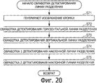
на фиг.20 показана блок-схема последовательности операций, поясняющая обработку детектирования линии разделения;20 is a flowchart for explaining detection processing of a dividing line;
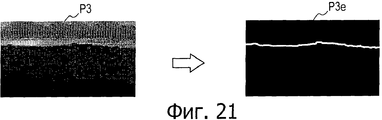
на фиг.21 показана схема, поясняющая входное изображение и изображение кромки;on Fig shows a diagram explaining the input image and the image of the edge;
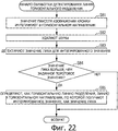
на фиг.22 показана блок-схема последовательности операций, поясняющая горизонтальную обработку детектирования линии разделения;FIG. 22 is a flowchart for explaining horizontal processing for detecting a dividing line; FIG.
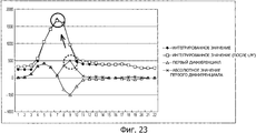
на фиг.23 показана схема, поясняющая значение интегрирования в горизонтальном направлении информации кромки;23 is a diagram for explaining the horizontal integration value of the edge information;
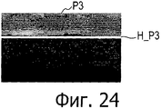
на фиг.24 показана схема, поясняющая пример результата детектирования горизонтальной линии разделения;Fig. 24 is a diagram for explaining an example of a detection result of a horizontal dividing line;
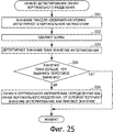
на фиг.25 показана блок-схема последовательности операций, поясняющая вертикальную обработку детектирования линии разделения;25 is a flowchart for explaining a vertical processing for detecting a dividing line;
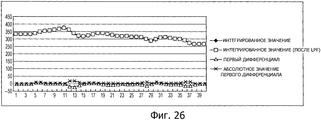
на фиг.26 показана схема, поясняющая значение интегрирования в вертикальном направлении информации кромки;on Fig shows a diagram explaining the value of integration in the vertical direction of the edge information;
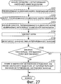
на фиг.27 показана блок-схема последовательности операций, поясняющая обработку детектирования наклонной линии разделения;Fig. 27 is a flowchart for explaining detection processing of an oblique separation line;
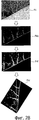
на фиг.28 показана схема, поясняющая входное изображение и изображение кромки, преобразование в двоичную форму изображения кромки и поворот изображения кромки;Fig. 28 is a diagram for explaining an input image and an image of an edge, binary conversion of an image of an edge, and rotation of an image of an edge;
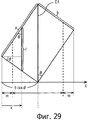
на фиг.29 показана схема, поясняющая пример нормализации значения интегрирования информации кромки каждой линии в направлении под наклоном;on Fig shows a diagram illustrating an example of normalizing the value of integrating the information of the edge of each line in the direction of the slope;
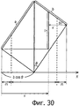
на фиг.30 показана схема, поясняющая пример нормализации значения интегрирования информации кромки каждой линии в направлении под наклоном;on Fig shows a diagram illustrating an example of normalizing the value of integrating the information of the edge of each line in the direction of the slope;
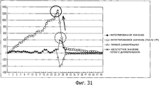
на фиг.31 показана схема, поясняющая значение интегрирования в направлении под наклоном информации кромки;on Fig shows a diagram explaining the value of integration in the direction at an angle of information of the edge;
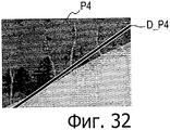
на фиг.32 показана схема, поясняющая пример результата детектирования наклонной линии разделения;Fig. 32 is a diagram for explaining an example of a detection result of an oblique separation line;
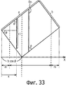
на фиг.33 показана схема, поясняющая другой пример нормализации значения интегрирования информации кромки каждой линии в направлении под наклоном;Fig. 33 is a diagram illustrating another example of normalizing the value of integrating the edge information of each line in an oblique direction;
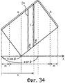
на. фиг.34 показана схема, поясняющая другой пример нормализации значения интегрирования информации кромки каждой линии в направлении под наклоном;on. Fig. 34 is a diagram illustrating another example of normalizing the value of integrating the edge information of each line in an oblique direction;
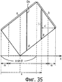
на фиг.35 показана схема, поясняющая другой пример нормализации значения интегрирования информации кромки каждой линии в направлении под наклоном;Fig. 35 is a diagram illustrating another example of normalizing the value of integrating the edge information of each line in an oblique direction;
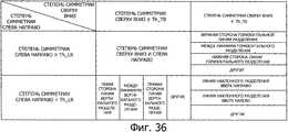
на фиг.36 показана схема, поясняющая пример структуры композиции, в которой классифицирована композиция входного изображения;Fig. 36 is a diagram for explaining an example of a composition structure in which an input image composition is classified;
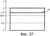
на фиг.37 показана схема, поясняющая пример структуры композиции, классифицированной на основе горизонтальной линии разделения;Fig. 37 is a diagram illustrating an example of a structure of a composition classified based on a horizontal separation line;
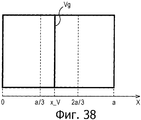
на фиг.38 показана схема, поясняющая пример структуры композиции, классифицированной на основе вертикальной линии разделения;Fig. 38 is a diagram illustrating an example of a structure of a composition classified based on a vertical separation line;
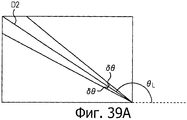
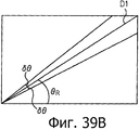
на фиг.39А и 39В представлены схемы, поясняющие примеры структуры композиции, классифицированной на основе наклонной линии разделения;on figa and 39B presents a diagram explaining examples of the structure of the composition, classified on the basis of an inclined line of separation;
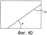
на фиг.40 показана схема, поясняющая пример структуры композиции, классифицированной на основе наклонной линии разделения;40 is a diagram illustrating an example of a structure of a composition classified based on an oblique separation line;
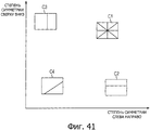
на фиг.41 показана схема, иллюстрирующая взаимосвязь между степенью симметрии и линией разделения;Fig. 41 is a diagram illustrating the relationship between the degree of symmetry and the separation line;
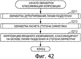
на фиг.42 показана блок-схема последовательности операций, поясняющая другую операцию обработки классификации композиции;Fig. 42 is a flowchart for explaining another operation of the composition classification processing;
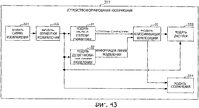
на фиг.43 показана блок-схема, иллюстрирующая пример функциональной конфигурации устройства формирования изображения;Fig. 43 is a block diagram illustrating an example of a functional configuration of an image forming apparatus;
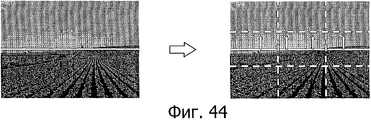
на фиг.44 показана схема, поясняющая пример отображения рекомендации композиции;on Fig shows a diagram explaining an example of displaying recommendations of the composition;
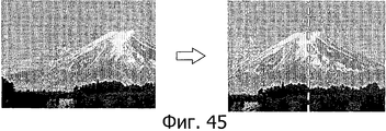
на фиг.45 показана схема, поясняющая пример отображения рекомендации композиции; иon Fig shows a diagram explaining an example of displaying recommendations of the composition; and
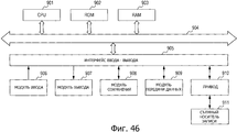
на фиг.46 показана блок-схема, иллюстрирующая пример конфигурации компьютерного оборудования.on Fig shows a block diagram illustrating an example configuration of computer equipment.
Подробное описание изобретенияDETAILED DESCRIPTION OF THE INVENTION
Ниже, со ссылкой на чертежи, будут описаны варианты осуществления раскрываемой в настоящее время технологии.Below, with reference to the drawings, embodiments of the presently disclosed technology will be described.
[Пример конфигурации устройства обработки изображений][An example configuration of an image processing apparatus]
На фиг.1 иллюстрируется пример функциональной конфигурации устройства обработки изображений в соответствии с вариантом осуществления раскрываемой в настоящее время технологии.1 illustrates an example of a functional configuration of an image processing apparatus in accordance with an embodiment of the presently disclosed technology.
Например, устройство 11 обработки изображений на фиг.1 рассчитывает степень симметрии, обозначающую симметрию линии входного изображения, вводимого из устройства формирования изображения, такого как цифровая камера и т.п., или другого устройства обработки изображений, и детектирует линию разделения, разделяющую входное изображение на заданные области. Кроме того, устройство 11 обработки изображений классифицирует композицию входного изображения на заданные структуры композиции (то есть классификации) на основе, по меньшей мере, одной из степени симметрии и линии разделения.For example, the
Устройство 11 обработки изображений включает в себя модуль 31 расчета степени симметрии, модуль 32 детектирования линии разделения и модуль 33 классификации композиции.The
Входное изображение, вводимое в устройство 11 обработки изображений, подают в модуль 31 расчета степени симметрии и модуль 32 детектирования линии разделения.The input image input to the
Модуль 31 расчета степени симметрии рассчитывает степень симметрии, обозначающую линию симметрии информации пикселя (значение пикселя) каждого из пикселей во входном изображении, относительно друг друга в направлении слева направо и в направлении сверху вниз входного изображения, и подает степень симметрии в модуль 33 классификации композиции.The symmetry
[Пример функциональной конфигурации модуля расчета степени симметрии][An example of the functional configuration of the module for calculating the degree of symmetry]
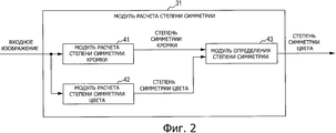
На фиг.2 иллюстрируется пример функциональной конфигурации модуля 31 расчета степени симметрии.Figure 2 illustrates an example of the functional configuration of the
Модуль 31 расчета степени симметрии включает в себя модуль 41 расчета степени симметрии кромки, модуль 42 расчета степени симметрии цвета и модуль 43 определения степени симметрии.The symmetry
Модуль 41 расчета степени симметрии кромки рассчитывает степень симметрии (ниже называется степенью симметрии кромки) для информации кромки, которая представляет собой тип информации о пикселе каждого из пикселей во входном изображении, и подает степень симметрии в модуль 43 определения степени симметрии.The edge symmetry
[Пример функциональной конфигурации модуля расчета степени симметрии кромки][An example of the functional configuration of the module for calculating the degree of symmetry of the edge]
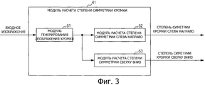
На фиг.3 иллюстрируется пример функциональной конфигурации модуля 41 расчета степени симметрии кромки.Figure 3 illustrates an example of the functional configuration of the
Модуль 41 расчета степени симметрии кромки включает в себя модуль 51 генерирования изображения кромки, модуль 52 расчета степени симметрии слева направо (то есть модуль расчета первой степени симметрии кромки) и модуль 53 расчета степени симметрии сверху вниз (то есть второй модуль расчета степени симметрии кромки).The edge
Модуль 51 генерирования изображения кромки генерирует изображение кромки, включающие в себя информацию кромки каждого из пикселей во входном изображении (то есть изображение кромки, которое обозначает кромки входного изображения), на основе каждого из пикселей и передает изображение кромки в модуль 52 расчета степеней симметрии слева направо и в модуль 53 расчета степени симметрии сверху вниз.The edge
Модуль 52 расчета степени симметрии слева направо рассчитывает степень симметрии кромки слева направо, то есть степень симметрии информации кромки относительно центральной линии в направлении слева направо в изображении кромки (то есть первая воображаемая линия на изображении кромки, которая параллельна стороне изображения кромки), подаваемой из модуля 51 генерирования изображения кромки, и выводит степень степени симметрии кромки слева направо.
Модуль 53 расчета степени симметрии сверху вниз рассчитывает степень симметрии кромки сверху вниз, которая представляет собой степень симметрии информации кромки относительно центральной линии в направлении сверху вниз в изображении кромки (то есть вторая воображаемая линия в изображении кромки, которая перпендикулярна первой воображаемой линии), передаваемом из модуля 51 генерирования изображения кромки, и выводит полученную степень симметрии кромки сверху вниз.The top-down symmetry
Таким образом, модуль 41 расчета степени симметрии кромки подает, как степень симметрии кромки, степень симметрии кромки слева направо и степень симметрии кромки сверху вниз в модуль 43 определения степени симметрии.Thus, the edge
Возвращаясь к описанию фиг.2, модуль 42 расчета степени симметрии цвета рассчитывает степень симметрии (ниже называется степенью симметрии цвета) информации цветов, которая представляет собой тип информации пикселя каждого из пикселей во входном изображении, и подает степень симметрии в модуль 43 определения степени симметрии.Returning to the description of FIG. 2, the color symmetry
[Пример функциональной конфигурации модуля расчета степени симметрии цвета][An example of the functional configuration of the module for calculating the degree of color symmetry]
На фиг.4 иллюстрируется пример функциональной конфигурации модуля 42 расчета степени симметрии цвета.Figure 4 illustrates an example of the functional configuration of the
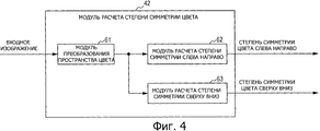
Модуль 42 расчета степени симметрии цвета включает в себя модуль 61 преобразования цветового пространства, модуль 62 расчета степени симметрии слева направо (то есть модуль расчета первой степени симметрии цвета) и модуль 63 расчета степени симметрии сверху вниз (то есть второй модуль расчета степени симметрии цвета).The color symmetry
Модуль 61 преобразования цветового пространства преобразует в другое цветовое пространство цветовое пространство, в котором представлена информация пикселя (информация цвета) каждого из пикселей во входном изображении, и подает в модуль 62 расчета степени симметрии слева направо и в модуль 63 расчета степени симметрии сверху вниз входное изображение, включающее в себя информацию о цвете, представленную в преобразованном цветовом пространстве.The color
Модуль 62 расчета степени симметрии слева направо рассчитывает степень симметрии цвета слева направо, которая представляет собой степень симметрии информации цвета относительно центральной линии в направлении слева направо во входном изображении (то есть первая воображаемая линия во входном изображении, которая параллельна стороне входного изображения), подаваемом из модуля 61 преобразования цветового пространства, и выводит степень симметрии цвета слева направо.The degree of
Модуль 63 расчета степени симметрии сверху вниз рассчитывает степень симметрии цвета сверху вниз, которая представляет собой степень симметрии информации цвета относительно центральной линии в направлении сверху вниз во входном изображении (то есть вторая воображаемая линия во входном изображении, которая перпендикулярна первой воображаемой линии), подаваемой из модуля 61 преобразования цветового пространства, и выводит степень симметрии цвета сверху вниз.The top-down symmetry
Таким образом, модуль 42 расчета степени симметрии цвета подает, как степень симметрии цвета, степень симметрии цвета слева направо и степень симметрии цвета сверху вниз в модуль 43 определения степени симметрии.Thus, the color
Возвращаясь к описанию фиг.2, на основе степени симметрии кромки, подаваемой из модуля 41 расчета степени симметрии кромки и степени симметрии цвета, подаваемой из модуля 42 расчета степени симметрии цвета, модуль 43 определения степени симметрии определяет степень симметрии слева направо, обозначающую линию симметрии относительно направления слева направо во входном изображении, и степень симметрии сверху вниз, обозначающую линию симметрии относительно направления сверху вниз во входном изображении. В частности, модуль 43 определения степени симметрии определяет, как степень симметрии слева направо, одну из степени симметрии кромки слева направо, подаваемую, как степень симметрии кромки, из модуля 41 расчета степени симметрии кромки, и степени симметрии цвета слева направо, подаваемую, как степень симметрии цвета, из модуля 42 расчета степени симметрии цвета, определенное значение, удовлетворяющее заданному условию. Кроме того, модуль 43 определения степени симметрии определяет, как степень симметрии сверху вниз, одну из степени симметрии кромки сверху вниз, подаваемую, как степень симметрии кромки из модуля 41 расчета степени симметрии кромки, и степени симметрии цвета сверху вниз, подаваемую, как степень симметрии цвета, из модуля 42 расчета степени симметрии цвета, определенную так, чтобы она удовлетворяла заданному условию.Returning to the description of FIG. 2, based on the degree of symmetry of the edge supplied from the edge
Таким образом, модуль 31 расчета степени симметрии подает, как степень симметрии, степень симметрии слева направо и степень симметрии сверху вниз, в модуль 33 классификации композиции.Thus, the degree of
Возвращаясь к описанию на фиг.1, модуль 32 детектирования линии разделения детектирует линию разделения для разделения входного изображения, по вариации распределения информации пикселя во входном изображении, и подает информацию линии разделения, обозначающую детектированную линию разделения, в модуль 33 классификации композиции.Returning to the description in FIG. 1, the separation
[Пример функциональной конфигурации модуля детектирования линии разделения][An example of the functional configuration of the separation line detection module]
На фиг.5 показан пример функциональной конфигурации модуля 32 детектирования линии разделения.Figure 5 shows an example of the functional configuration of the
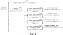
Модуль 32 детектирования линии разделения включает в себя модуль 71 генерирования изображения кромки, модуль 72 детектирования горизонтальной линии разделения (то есть модуль детектирования первой линии разделения), модуль 73 детектирования вертикальной линии разделения (то есть модуль детектирования второй линии разделения) и модули 74 и 75 детектирования наклонной линии разделения (то есть модули детектирования третьей и четвертой линии разделения).The dividing
Таким же образом, как и модуль 51 генерирования изображения кромки на фиг.3, модуль 71 генерирования изображения кромки генерирует изображение кромки, включающее в себя информацию кромки каждого из пикселей во входном изображении, на основе каждого из пикселей, и подает изображение кромки в модуль 72 детектирования горизонтальной линии разделения в модуль 75 детектирования линии разделения под наклоном.In the same manner as the edge
Модуль 72 детектирования горизонтальный линии разделения интегрирует информацию кромки в горизонтальном направлении в изображении кромки, подаваемом из модуля 71 генерирования изображения кромки, и детектирует линию горизонтального разделения (то есть первую линию разделения), разделяющую входное изображение в горизонтальном направлении (а именно наверх и вниз), по распределению значения его интегрирования. Модуль 72 детектирования горизонтальной линии разделения выводит информацию линии горизонтального разделения, обозначающую детектированную горизонтальную линию разделения.The horizontal dividing
Модуль 73 детектирования вертикальной линии разделения интегрирует информацию кромки в вертикальном направлении в изображении кромки, подаваемом из модуля 71 генерирования изображения кромки, и детектирует линию вертикального разделения (то есть вторую линию разделения, которая расположена под углом относительно первой линии разделения), которая разделяет входное изображение в вертикальном направлении (а именно на правую и левую части), по распределению его интегрированного значения. Модуль 73 детектирования вертикальной линии разделения выводит информацию вертикальной линии разделения, обозначающую детектированную вертикальную линию разделения.The vertical dividing
Модуль 74 детектирования наклонной линии разделения интегрирует информацию кромки в наклонном направлении вверх и вправо в изображении кромки, подаваемом из модуля 71 генерирования изображения кромки, и детектирует наклонную линию разделения, направленную вверх и вправо (то есть третью линию разделения, которая расположена под углом относительно первой и второй линий разделения), которая разделяет входное изображение в наклонном направлении вверх и вправо, по распределению ее интегрированного значения. Модуль 74 детектирования наклонной линии разделения выводит первую информацию наклонной линии разделения, обозначающую детектированную наклонную линию разделения в направлении вверх и вправо.The oblique dividing
Модуль 75 детектирования наклонной линии разделения интегрирует информацию кромки в наклонном направлении вверх и влево в изображении кромки, подаваемом из модуля 71 генерирования изображения кромки, и детектирует наклонную линию разделения в направлении верх и влево (то есть четвертую линию разделения, которая расположена под углом относительно первой, второй и третьей линий разделения), которые разделяют входное изображение в наклонном направлении вверх и влево, из распределения его интегрального значения. Модуль 75 детектирования наклонной линии разделения выводит информацию наклонной линии разделения, обозначающую детектированную наклонную линию разделения в направлении вверх и влево.The oblique dividing
Таким образом, в качестве информации линии разделения модуль 32 детектирования линии разделения подает информацию линии горизонтального разделения, информацию линии вертикального разделения, первую информацию наклонной линии разделения и вторую информацию наклонной линии разделения в модуль 33 классификации композиции.Thus, as the separation line information, the separation
Здесь со ссылкой на фиг.6-8 представлены примеры функциональной конфигурации от модуля 72 детектирования горизонтальной линии разделения до модуля 75 детектирования наклонной линии разделения.Here, with reference to FIGS. 6-8, examples of a functional configuration are presented from the horizontal dividing
[Пример функциональной конфигурации модуля детектирования горизонтальной линии разделения][An example of the functional configuration of the module for detecting the horizontal separation line]
На фиг.6 иллюстрируется пример функциональной конфигурации модуля 72 детектирования горизонтальной линии разделения.6 illustrates an example of a functional configuration of a horizontal separation
Модуль 72 детектирования горизонтальной линии разделения включает в себя модуль 111 интегрирования в горизонтальном направлении, фильтр 112 низкой частоты (LPF), модуль 113 детектирования значения пика и модуль 114 обработки порогового значения.The horizontal dividing
Модуль 111 интегрирования в горизонтальном направлении интегрирует информацию пикселя (информацию кромки) пикселя относительно каждой из линий, включающих в себя пиксели (ниже просто называется линией) в горизонтальном направлении, в изображении кромки, подаваемом из модуля 71 генерирования изображения кромки, и подает результат ее интегрирования в LPF 112. Результат интегрирования, получаемый здесь, представляет собой значение интегрирования информации кромки в горизонтальном направлении, относительно положения пикселя в вертикальном направлении в изображении кромки (входное изображение).The
В результате выполнения процесса обработки фильтрации для результата интегрирования из модуля 111 интегрирования в горизонтальном направлении, а именно значения интегрирования информации кромки в горизонтальном направлении относительно положения пикселя в вертикальном направлении в изображении кромки, LPF 112 удаляет шумы из результата интегрирования и подает результат интегрирования в модуль 113 детектирования значения пика.As a result of performing the filtering processing process for the integration result from the
Модуль 113 детектирования значения пика детектирует значение пика для значения интегрирования из результата интегрирования, из которого были удалены шумы с помощью LPF 112, и подает в модуль 114 обработки порогового значения детектированное значение пика и положение пикселя в вертикальном направлении линии, продолжающейся в горизонтальном направлении, на которой было получено значение интегрирования, представляющее собой значение пика.The peak
Модуль 114 обработки порогового значения сравнивает значение пика из модуля 113 детектирования значения пика с заданным пороговым значением. Кроме того, когда значение пика больше, чем заданное пороговое значение, модуль 114 обработки порогового значения определяет, как горизонтальную линию разделения, линию в горизонтальном направлении, от которой получают значение интегрирования, которое должно быть значением пика, и выводит как информацию горизонтальной линии разделения положение пикселя в вертикальном направлении линии в изображении кромки.The threshold
[Пример функциональной конфигурации модуля детектирования линии вертикального разделения][An example of the functional configuration of the module for detecting the vertical separation line]
На фиг.7 иллюстрируется пример функциональной конфигурации модуля 73 детектирования линии вертикального разделения.7 illustrates an example of a functional configuration of a vertical separation
Модуль 73 детектирования линии вертикального разделения включает в себя модуль 121 интегрирования в вертикальном направлении, LPF 122, модуль 123 детектирования значения пика и модуль 124 обработки порогового значения.The vertical dividing
Модуль 121 интегрирования в вертикальном направлении интегрирует информацию кромки относительно каждой из линий в вертикальном направлении в изображении кромки, подаваемом из модуля 71 генерирования изображения кромки, и передает результат его интегрирования в LPF 122. Полученный здесь результат интегрирования представляет собой значение интегрирования информации кромки в вертикальном направлении относительно положения пикселя в горизонтальном направлении в изображении кромки (входное изображение).The
В результате выполнения обработки фильтрации результата интегрирования из модуля 121 интегрирования в вертикальном направлении, а именно значения интегрирования информации кромки в вертикальном направлении относительно положения пикселя в горизонтальном направлении в изображении кромки, LPF 122 удаляет шумы из результата интегрирования и подает результат интегрирования в модуль 123 детектирования значения пика.As a result of the filtering processing of the integration result from the
Модуль 123 детектирования значения пика детектирует значение пика для значения интегрирования из результата интегрирования, из которого были удалены шумы с помощью LPF 122, и подает в модуль 124 обработки порогового значения детектированное значение пика и положение пикселя в горизонтальном направлении линии, в вертикальном направлении, от которой получают значение интегрирования как значение пика.The peak
Модуль 124 обработки порогового значения сравнивает пиковое значение из модуля 123 детектирования значения пика с заданным пороговым значением. Кроме того, когда значение пика больше, чем заданное пороговое значение, модуль 124 обработки порогового значения определяет, как вертикальную линию разделения, линию в вертикальном направлении, от которой получают значение интегрирования, которое должно представлять собой значение пика, и выводит, как информацию вертикальной линии разделения, положение пикселя в горизонтальном направлении на линии на кромке изображении.The threshold
[Пример функциональной конфигурации модуля детектирования наклонной линии разделения][An example of a functional configuration of an inclined separation line detection module]
На фиг.8 иллюстрируется пример функциональной конфигурации модуля 74 детектирования наклонной линии разделения.On Fig illustrates an example of a functional configuration of the
Модуль 74 детектирования наклонной линии разделения включает в себя модуль 131 интегрирования наклонного направления, LPF 132, модуль 133 детектирования пикового значения и модуль 134 обработки порогового значения.The oblique dividing
Модуль 131 интегрирования наклонного направления интегрирует информацию кромки относительно каждой из линий в наклонном направлении вверх и вправо в изображении кромки, подаваемом из модуля 71 генерирования изображения кромки, и подает его результат интегрирования в LPF 132. Результат интегрирования, полученный здесь, представляет собой значение интегрирования информации кромки в наклонном направлении вверх и вправо относительно положения пикселя в наклонном направлении вверх и влево в изображении кромки (входное изображение).The oblique
В результате выполнения обработки фильтрации для результата интегрирования из модуля 131 интегрирования наклонного направления, а именно значения интегрирования информации кромки в наклонном направлении вверх и вправо относительно положения пикселя в наклонном направлении вверх и влево на изображении кромки, LPF 132 удаляет шумы из результата интегрирования и подает результат интегрирования в модуль 133 детектирования значения пика.As a result of performing filtering processing for the integration result from the inclined
Модуль 133 детектирования значения пика детектирует значение пика для значения интегрирования из результата интегрирования, из которого шумы были удалены с помощью LPF 132, и подает в модуль 134 обработки порогового значения детектированное значение пика и положение пикселя в наклонном направлении вверх и влево линии наклонного направления вверх и вправо, от которой получают значение интегрирования, которое должно представлять собой значение пика.The peak
Модуль 134 обработки порогового значения сравнивает значение пика из модуля 133 детектирования значения пика с заданным пороговым значением. Кроме того, когда значение пика больше чем заданное пороговое значение, модуль 114 обработки порогового значения определяет, как наклонную линию разделения вверх и вправо, линию в наклонном направлении вверх и вправо, от которой было получено значение интегрирования, которое должно представлять собой значение пика, и выводит, как информацию первой линии разделения, положение пикселя в наклонном направлении вверх и влево линии на кромке изображения.The threshold
Кроме того, пример функциональной конфигурации модуля 75 детектирования наклонной линии разделения, в основном, является тем же, что и модуль 74 детектирования наклонной линии разделения по фиг.8 за исключением того, что в отдельных модулях модуля 74 детектирования наклонной линии разделения обработка для наклонного направления вверх и вправо информации кромки заменяется обработкой для наклонного направления вверх и влево информации кромки. Поэтому ее описание будет исключено.In addition, an example of the functional configuration of the oblique dividing
Кроме того, возвращаясь к описанию на фиг.1, модуль 33 классификации композиции классифицирует композицию во входном изображении на одну из заранее определенных структур композиции, на основе степени симметрии из модуля 31 расчета степени симметрии и информации линии разделения из модуля 32 детектирования линии разделения и выводит структуру композиции вместе со степенью симметрии и информацией линии разделения в устройство обработки информации, устройство сохранения и т.п., которые не показаны.In addition, returning to the description in FIG. 1, the
[Обработка классификации композиции, выполняемая в устройстве обработки изображения][Composition classification processing performed in the image processing apparatus]
Далее, со ссылкой на блок-схему последовательности операций, показанную на фиг.9, будет описана обработка классификации композиции, выполняемая в устройстве 11 обработки изображения на фиг.1.Next, with reference to the flowchart shown in FIG. 9, the composition classification processing performed in the
Композицию входного изображения, подаваемого в устройство 11 обработки изображения, классифицируют на одну из заранее определенных структур композиции на основе обработки классификации композиции, представленной в блок-схеме последовательности операций на фиг.9.The composition of the input image supplied to the
Здесь структура композиции, обычно рекомендованная при фотосъемке и т.п., будет описана со ссылкой на фиг.10.Here, the structure of the composition, usually recommended when photographing, etc., will be described with reference to Fig.10.
Структура С композиции, иллюстрируемая на фиг.10, включает в себя две репрезентативные структуры композиции, такие как композиция, основанная на правиле трех, и диагональная композиция.The composition structure C illustrated in FIG. 10 includes two representative composition structures, such as a composition based on rule three, and a diagonal composition.
Композиция, основанная на правиле трех, представляет собой композицию, включающую в себя горизонтальные линии H1 и Н2 разделения и вертикальные линии V1 и V2 разделения, называемые линиями деления на 3. Кроме того, установлена граница субъекта или ландшафта, по меньшей мере, на одной линии из горизонтальных линий H1 и Н2 разделения и вертикальных линий V1 и V2 разделения, или субъект расположен в одной из четырех точек пересечения (точек пересечения линии деления на 3) между линиями H1 и Н2 горизонтального разделения и линиями V1 и V2 вертикального разделения, обеспечивая, таким образом, возможность получения хорошо сбалансированного изображения.A composition based on rule three is a composition including horizontal dividing lines H1 and H2 and vertical dividing lines V1 and V2, called dividing lines by 3. In addition, a subject or landscape boundary is set on at least one line of horizontal separation lines H1 and H2 and vertical separation lines V1 and V2, or the subject is located at one of four intersection points (points of intersection of the division line by 3) between the horizontal separation lines H1 and H2 and the vertical section lines V1 and V2 Helen, thus providing the possibility of obtaining a well-balanced image.
Кроме того, диагональная композиция представляет собой композицию, включающую в себя диагональные линии D1 и D2, и границу субъекта или ландшафта устанавливают, по меньшей мере, на одной линии из диагональных линий D1 и D2, обеспечивая, таким образом, возможность получения хорошо сбалансированного изображения.In addition, the diagonal composition is a composition including the diagonal lines D1 and D2, and the boundary of the subject or landscape is set on at least one line of the diagonal lines D1 and D2, thus providing the possibility of obtaining a well-balanced image.
При обработке классификации композиции, описанной ниже, определяют, насколько симметричной является композиция входного изображения относительно направления слева направо или направления вверх и вниз или на какую из описанных выше композиций на основе правила трех или диагональной композиции похожа композиция входного изображения.When processing the classification of the composition described below, it is determined how symmetrical the composition of the input image is relative to the direction from left to right or direction up and down, or to which of the above compositions based on the rule of three or diagonal composition the composition of the input image is similar.
На этапе S11 в блок-схеме последовательности операций на фиг.9 модуль 31 расчета степени симметрии выполняет обработку расчета степени симметрии и рассчитывает степень симметрии информации пикселя каждого из пикселей во входном изображении относительно каждого из направления слева направо и направления сверху вниз входного изображения.In step S11, in the flowchart of FIG. 9, the degree of
[Обработка расчета степени симметрии, выполняемая в модуле расчета степени симметрии][Processing the calculation of the degree of symmetry performed in the module for calculating the degree of symmetry]
Здесь обработка расчета степени симметрии, выполняемая на этапе S11 в блок-схеме последовательности операций на фиг.9, будет описана со ссылкой на блок-схему последовательности операций на фиг.11.Here, the symmetry degree calculation processing performed in step S11 in the flowchart of FIG. 9 will be described with reference to the flowchart of FIG. 11.
На этапе S31 модуль 41 расчета степени симметрии кромки в модуле 31 расчета степени симметрии выполняет обработку расчета степени симметрии кромки и рассчитывает степень симметрии кромки входного изображения.In step S31, the edge
[Обработка расчета степени симметрии кромки, выполняемая в модуле расчета степени симметрии кромки][Processing for calculating the degree of symmetry of an edge performed in the module for calculating the degree of symmetry of an edge]
Здесь обработка расчета степени симметрии кромки, выполняемая на этапе S31 в блок-схеме последовательности операций на фиг.11, будет описана со ссылкой на блок-схему последовательности операций на фиг.12.Here, the edge symmetry degree calculation processing performed in step S31 in the flowchart of FIG. 11 will be described with reference to the flowchart of FIG. 12.
На этапе S41 модуль 51 генерирования изображения кромки в модуле 41 расчета степени симметрии кромки получает изображение яркости из входного изображения и генерирует изображение кромки, которое включает в себя значение кромки (информацию кромки), полученную путем применения фильтра выделения кромки, такого как фильтр Собеля, фильтр Габора и т.п., в изображении яркости.In step S41, the edge
Кроме того, модуль 51 генерирования изображения кромки может получать изображения каналов цвета, таких как R, G, В и т.п., из входного изображения, сравнивать значения кромки, полученные индивидуально, применяя фильтр выделения кромки с цветным изображениями канала, друг с другом между каналами относительно каждого пикселя, и генерировать изображение кромки, включающее в себя индивидуальное максимальное значение.In addition, the edge
Кроме того, модуль 51 генерирования изображения кромки также может выполнять разделение области по цвету, в котором используется алгоритм среднего сдвига (способ сдвига среднего) и т.п., для входного изображения, и генерировать изображение кромки путем назначения значения кромки для пикселя на граничной линии разделенной области. Например, в этом случае значение "1" кромки назначают для пикселя на граничной области, и значение "0" кромки назначают для пикселя в другой области, кроме граничной линии.In addition, the edge
Например, когда, как показано на фиг.13, изображение сцены, в которой субъект представляет собой гору, вводят, как входное изображение Р1, модуль 51 генерирования изображения кромки генерирует изображение P1e кромки, которое обозначает форму профиля сцены, включающей в себя гору. Изображение P1e кромки, сгенерированное таким образом, подают в модуль 52 расчета степеней симметрии слева направо и в модуль 53 расчета степени симметрии сверху вниз.For example, when, as shown in FIG. 13, an image of a scene in which the subject is a mountain is input as an input image P1, an edge
На этапе S42, модуль 52 расчета степеней симметрии слева направо рассчитывает степень для степени симметрии кромки слева направо, которая представляет собой степень симметрии слева направо изображения кромки, на основе изображения кромки, подаваемого из модуля 51 генерирования изображения кромки.In step S42, the left-to-right degree of
Здесь пример расчета степени для степени симметрии кромки слева направо будет описан со ссылкой на фиг.14. На фиг.14 иллюстрируется изображение P1e кромки.Here, an example of calculating a degree for a degree of symmetry of an edge from left to right will be described with reference to FIG. On Fig illustrates the image P1e edge.
Как показано на фиг.14, если изображение P1e кромки включает в себя Н×W пиксели, центральная линия в направлении слева направо в изображении P1e кромки представляет собой линию, расположенную в положении W/2 пикселей.As shown in FIG. 14, if the edge image P1e includes H × W pixels, the center line from left to right in the edge image P1e is a line located at the W / 2 pixel position.
Кроме того, внимание сфокусировано на линии в горизонтальном направлении, в положении пикселя в направлении вверх вниз, которое обозначено "i", и предполагается, что положение пикселя для пикселя, расположенного на j пикселей с правой стороны от пикселя (пикселя, положение пикселя которого представляет собой W/2) на центральной линии в направлении слева направо, представлено как "+j", и положение пикселя для пикселя, расположенного на j пикселей с левой стороны от пикселя на центральной линии в горизонтальном направлении, представлено как "-j".In addition, attention is focused on the line in the horizontal direction, in the up-down position of the pixel, which is denoted by “i”, and it is assumed that the position of the pixel for the pixel located at j pixels to the right of the pixel (the pixel whose pixel position represents itself W / 2) on the center line in the direction from left to right, is represented as “+ j”, and the pixel position for the pixel located j pixels to the left of the pixel on the center line in the horizontal direction is represented as “-j”.
В это время в изображении P1e кромки, сумма d разности между частями информации кромки пары пикселей, расположенных на противоположных сторонах от центральной линии в направлении слева направо (их положение пикселя составляет W/2), положения пикселя пары пикселей, представляющих положения пикселя (i, j) и (i, - j) (ниже просто называется положением пикселя (i, j)), и сумма s частей информации кромки пар пикселей, расположенных на противоположных сторонах от центральной линии в направлении слева направо (а именно сумма частей информации кромки всех пикселей), обозначена следующими выражениями (1) и (2), соответственно.At this time, in the edge image P1e, the sum d of the difference between the pieces of information of the edge of the pair of pixels located on opposite sides of the center line from left to right (their pixel position is W / 2), the pixel position of the pair of pixels representing the position of the pixel (i, j) and (i, - j) (hereinafter simply referred to as the position of the pixel (i, j)), and the sum s of the pieces of information of the edge of the pairs of pixels located on opposite sides of the center line from left to right (namely, the sum of the pieces of information of the edge of all pi mudflow) is designated by the following expressions (1) and (2), respectively.


В выражениях (1) и (2) коэффициент w представляет собой взвешивающий коэффициент, степень взвешивания которого уменьшается при увеличении расстояния положения пикселя (i, j) для пикселя, на котором сосредоточено внимание, от центральной точки входного изображения, положение (i, j) пикселя определяют относительно центра кромки изображения, и когда расстояние положения (i, j) пикселя от центральной точки входного изображения будет обозначено, как r, коэффициент w будет обозначен следующим выражением (3)In expressions (1) and (2), the coefficient w is a weighting coefficient, the degree of weighing of which decreases with increasing distance of the position of the pixel (i, j) for the pixel on which the attention is focused from the center point of the input image, the position (i, j) pixels are determined relative to the center of the edge of the image, and when the distance of the position (i, j) of the pixel from the center point of the input image is denoted by r, the coefficient w will be denoted by the following expression (3)
![]()
![]()
Кроме того, предполагается, что константа σ в выражении (3) представляет собой произвольно установленное значение.In addition, it is assumed that the constant σ in expression (3) is an arbitrarily set value.
"Сумма разностей между частями информации кромки" d, обозначенная выражением (1), имеет значение, приближающееся к "0", которое увеличивается при симметрии слева направо изображения P1e кромки, и "сумма разностей между частями информации кромки" d имеет значение, приближающееся к "сумме частей информации кромки" s, и увеличивается при асимметрии слева направо изображения P1e кромки. Поэтому степень симметрии кромки слева направо sym_edg_LR, которая представляет собой степень симметрии слева направо изображения кромки, обозначена следующим выражением (4).The "sum of the differences between the pieces of information of the edge" d, denoted by the expression (1), has a value approaching "0", which increases with symmetry from left to right of the image P1e of the edge, and the "sum of the differences between the pieces of information of the edge" d has a value approaching "the sum of the pieces of edge information" s, and increases with asymmetry from left to right of the edge image P1e. Therefore, the degree of symmetry of the edge from left to right sym_edg_LR, which is the degree of symmetry from left to right of the image of the edge, is indicated by the following expression (4).
![]()
![]()
А именно степень симметрии кромки слева направо sym_edg_LR имеет значение, диапазон которого составляет 0<sym_edg_LR<1, и имеет значение, приближающееся к "1" при увеличении симметрии слева направо изображения P1e кромки.Namely, the degree of symmetry of the edge from left to right sym_edg_LR has a value whose range is 0 <sym_edg_LR <1, and has a value approaching "1" with increasing symmetry from left to right of the image P1e of the edge.
Таким образом, рассчитывают степень степени кромки слева направо.Thus, the degree of the degree of the edge is calculated from left to right.
Возвращаясь к блок-схеме последовательности операций на фиг.12, на этапе S43, модуль 53 расчета степени симметрии сверху вниз рассчитывает степень симметрии кромки сверху вниз, которая представляет собой степень симметрии сверху вниз изображения кромки, на основе изображения кромки, подаваемого из модуля 51 генерирования изображения кромки.Returning to the flowchart in FIG. 12, in step S43, the top-down symmetry
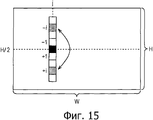
Кроме того, что касается степени симметрии кромки сверху вниз sym_edg_TB, как показано на фиг.15, предполагается, что центральная линия в направлении вверх вниз изображения P1e кромки представляет собой линию, положение пикселя которой составляет Н/2, и внимание фокусируется на линии, включающей в себя пиксели в вертикальном направлении, расположенном в положении j пикселя в направлении слева направо. Кроме того, когда предполагается, что положение пикселя для пикселя, расположенного на расстоянии i пикселей от на нижней стороны от пикселя (пикселя, положение пикселя которого составляет Н/2) на центральной линии в направлении вверх вниз, представлено как "+i", и положение пикселя для пикселя, расположенного на i пикселей с верхней стороны от пикселя на центральной линии в направлении вверх вниз, представлено как "-i", степень симметрии кромки в направлении сверху вниз, sym_edg_TB, рассчитывают путем замены значения Н и значения W друг на друга в выражениях (1) и (2), так же, как и степень симметрии кромки слева направо sym_edg_LR.In addition, with respect to the degree of symmetry of the top-down edge sym_edg_TB, as shown in FIG. 15, it is assumed that the center line in the up-down direction of the edge image P1e is a line whose pixel position is H / 2, and attention is focused on a line including pixels in a vertical direction located at a pixel position j in a direction from left to right. Further, when it is assumed that a pixel position for a pixel located at a distance of i pixels from the lower side of the pixel (a pixel whose pixel position is H / 2) on the center line in an upward downward direction is represented as “+ i”, and the pixel position for a pixel located i pixels from the top side of the pixel on the center line in the up-down direction is represented by "-i", the degree of symmetry of the edge in the top-down direction, sym_edg_TB, is calculated by replacing the value of H and the value of W with each other in vyr (1) and (2), as well as the degree of symmetry of the edge from left to right sym_edg_LR.
Таким образом, рассчитывают степень симметрии кромки сверху вниз.Thus, the degree of symmetry of the edge from top to bottom is calculated.
После этапа S43 обработка возвращается на этап S31 в блок-схему последовательности операций на фиг.11 и переходит на этап S32.After step S43, the processing returns to step S31 in the flowchart of FIG. 11 and proceeds to step S32.
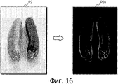
В частности, когда, как входное изображение, вводят входное изображение Р2, в котором овощи, как субъекты съемки, имеющие приблизительно одинаковую форму и разные цвета, размещены рядом друг с другом, как представлено с левой стороны на фиг.16, изображение Р2е кромки, показанное с правой стороны на фиг.16, генерируют при обработке расчета степени симметрии кромки.In particular, when, as an input image, an input image P2 is introduced in which vegetables, as subjects of shooting, having approximately the same shape and different colors, are placed next to each other, as shown on the left side in FIG. 16, an edge image P2e, shown on the right side in FIG. 16 is generated by processing the calculation of the degree of symmetry of the edge.
Поскольку изображение Р2е кромки, показанное на фиг.16, имеет высокую линейную симметрию относительно направления слева направо, большое значение получают, как степень симметрии кромки слева направо. Однако поскольку цвета субъектов, размещенных рядом друг с другом, отличаются друг от друга в фактическом входном изображении Р2, нет необходимости обеспечивать высокое значение линейной симметрии относительно направления слева направо.Since the edge image P2e shown in FIG. 16 has high linear symmetry with respect to the direction from left to right, great importance is obtained as the degree of symmetry of the edge from left to right. However, since the colors of the subjects placed next to each other differ from each other in the actual input image P2, it is not necessary to provide a high value of linear symmetry with respect to the direction from left to right.
Таким образом, при обработке расчета степени симметрии кромки трудно получить симметрию линии для цвета входного изображения.Thus, when processing the calculation of the degree of edge symmetry, it is difficult to obtain line symmetry for the color of the input image.
Поэтому на этапе S32 модуль 42 расчета степени симметрии цвета выполняет обработку расчета степени симметрии цвета и рассчитывает степень симметрии цвета во входном изображении, получая, таким образом, симметрию линии цвета входного изображения.Therefore, in step S32, the color symmetry
[Обработка расчета степени симметрии цвета, выполняемая в модуле расчета степени симметрии цвета][Processing for calculating the degree of symmetry of color, performed in the module for calculating the degree of symmetry of color]
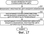
Здесь будет описана, со ссылкой на блок-схему последовательности операций, показанную на фиг.17, обработка, выполняемая при расчете степени симметрии цвета, выполняемая на этапе S31, в блок-схеме последовательности операций, показанной на фиг.11.Here, with reference to the flowchart shown in FIG. 17, the processing performed in calculating the degree of color symmetry performed in step S31 will be described in the flowchart shown in FIG. 11.
На этапе S51, модуль 61 преобразования пространства цвета преобразует пространство цвета так, что отдельные пиксели во входном изображении, представленные пространством RGB, будут представлены, например, пространством L*a*b*. Модуль 61 преобразования пространства цвета подает входное изображение, представленное пространством L*a*b*, в модуль 62 расчета степени симметрии слева направо и в модуль 63 расчета степени симметрии сверху вниз.In step S51, the color
На этапе S52 модуль 62 расчета степени симметрии слева направо рассчитывает степень симметрии цвета слева направо, которая представляет собой степень симметрии слева направо входного изображения, пространство цвета которого было преобразовано модулем 61 преобразования пространства цвета, входное изображение представлено пространством L*a*b*.In step S52, the degree of
Здесь будет описан пример расчета степени симметрии цвета слева направо. Кроме того, предполагается, что входное изображение, представленное пространством L*a*b*, выражено таким же образом, как и изображение P1e кромки, описанное со ссылкой на фиг.14.An example of calculating the degree of color symmetry from left to right will be described here. In addition, it is assumed that the input image represented by the space L * a * b * is expressed in the same way as the edge image P1e described with reference to Fig. 14.
В это время во входном изображении сумма D разности цветов между парой пикселей, расположенных на противоположных сторонах центральной линии в направлении слева направо (положение их пикселя представляет собой W/2), положения пикселя пары пикселей, представляющих собой положение (i, j), пикселя, обозначены следующим выражением (5).At this time, in the input image, the sum D of the color difference between a pair of pixels located on opposite sides of the center line from left to right (their pixel position is W / 2), the pixel position of a pair of pixels representing the position (i, j) of the pixel are denoted by the following expression (5).

В выражении (5) разность dE цветов между пикселями, расположенными в положении (i, j) пикселя, разность dL между их компонентами L на L* оси, разность da между их компонентами а на оси а* и разность db между их компонентами b на оси b* индивидуально обозначены следующим выражением (6).In expression (5), the difference dE of the colors between the pixels located at the position (i, j) of the pixel, the difference dL between their components L on the L * axis, the difference d a between their components a on the a * axis and the difference db between their components b on the b * axis are individually indicated by the following expression (6).

Кроме того, коэффициент w в выражении (5) представляет собой взвешивающие коэффициенты, относящимся к разности dE цветов между пикселями, расположенными в положении (i, j) пикселей, и коэффициент w обозначен следующим выражением (7).In addition, the coefficient w in expression (5) is weighting coefficients related to the color difference dE between the pixels located at the position (i, j) of the pixels, and the coefficient w is denoted by the following expression (7).
![]()
![]()
В выражении (7) взвешивающий коэффициент wp представляет собой взвешивающий коэффициент, взвешивающая способность которого уменьшается при увеличении расстояния положения (i, j) пикселя от центральной точки входного изображения, и взвешивающий коэффициент wp обозначен следующим выражением (8).In expression (7), the weighting coefficient w p is a weighting coefficient, the weighing ability of which decreases with increasing position distance (i, j) of the pixel from the center point of the input image, and the weighting coefficient w p is indicated by the following expression (8).

Кроме того, предполагается, что постоянная β в выражении (8) представляет собой произвольно установленное значение.In addition, it is assumed that the constant β in expression (8) is an arbitrarily set value.
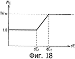
Кроме того, в выражении (7), взвешивающий коэффициент wЕ представляет собой взвешивающий коэффициент, взвешивающая функция которого будет выше в области, в которой разность цветов dE между пикселями, расположенными в положении (i, j) пикселя, на которое направлено внимание, будет больше, и взвешивающий коэффициент wЕ имеет такую характеристику, как показана на фиг.18. В частности, когда разность dE цветов будет меньше, чем значение dE1, взвешивающий коэффициент wE имеет значение 1,0, и когда разность dE цветов будет больше, чем значение dE2, взвешивающий коэффициент wE имеет значение wEM. Кроме того, когда разность dE цветов находится в диапазоне от значения dE1 до значения dE2, взвешивающий коэффициент wE также увеличивается в соответствии с увеличением разности dE цветов.In addition, in expression (7), the weighting coefficient w E is a weighting coefficient, the weighting function of which will be higher in the region in which the color difference dE between the pixels located in the position (i, j) of the pixel to which attention is directed will be more, and the weighting coefficient w E has such a characteristic as shown in FIG. In particular, when the color difference dE is less than the value dE 1 , the weighting coefficient w E has a value of 1.0, and when the color difference dE is larger than the value dE 2 , the weighting coefficient w E has the value w EM . In addition, when the color difference dE is in the range from the value dE 1 to the value dE 2 , the weighting coefficient w E also increases in accordance with the increase in the color difference dE.
А именно взвешивающий коэффициент wЕ взвешивают относительно разности dE цветов таким образом, что разность dE цветов будет в большей степени выражена для области, цвета которой значительно изменяются справа налево, таким образом, как входное изображение Р2, показанное на фиг.16.Namely, the weighting coefficient w E is weighed relative to the color difference dE in such a way that the color difference dE will be more pronounced for a region whose colors change significantly from right to left, such as the input image P2 shown in FIG. 16.
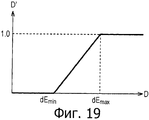
В соответствии с этим, в то время как "сумма разности цветов" D, обозначенная выражением (5), имеет значение, которое уменьшается при увеличении симметрии слева направо цветов во входном изображении, и имеет значение, которое увеличивается с увеличением асимметрии слева направо цвета входного изображения, "сумму разности цветов" D преобразуют, как показано на фиг.19, для того, чтобы было легче с ней работать.Accordingly, while the “sum of the color difference” D, denoted by expression (5), has a value that decreases with increasing symmetry from left to right in the input image, and has a value that increases with increasing asymmetry from left to right of the color of the input images, the "sum of the color difference" D is converted, as shown in Fig. 19, in order to make it easier to work with.
А именно в соответствии с фиг.19, когда сумма разности D цветов будет меньше, чем минимальное значение dEmin разности dE цветов между пикселями, расположенными в положении (i, j) пикселя, сумма разности D' цветов после преобразования имеет значение "0", и когда сумма разности D цветов больше, чем максимальное значение dEmax разности dE цветов между пикселями, расположенными в положении (i, j) пикселя, сумма разности D' цветов после преобразования имеет значение "1". Кроме того, когда сумма разности D цветов находится в диапазоне от dEmin до dEmax, сумма разности D' цветов после преобразования также увеличивается в ответ на увеличение суммы разности D цветов.Namely, in accordance with FIG. 19, when the sum of the color difference D is smaller than the minimum value dE min of the color difference dE between the pixels located at the pixel position (i, j), the sum of the color difference D ′ after the conversion has a value of “0” and when the sum of the color difference D is greater than the maximum value dE max of the color difference dE between the pixels located at the position (i, j) of the pixel, the sum of the color difference D ′ after the conversion has a value of “1”. In addition, when the sum of the difference of D colors is in the range from dE min to dE max , the sum of the difference of D 'colors after conversion also increases in response to an increase in the sum of the difference of D colors.
Кроме того, степень симметрии цветов слева направо sym_col_LR, которая представляет собой степень симметрии слева направо цвета во входном изображении, обозначена следующим выражением (9).In addition, the degree of symmetry of the colors from left to right sym_col_LR, which is the degree of symmetry from left to right of the color in the input image, is indicated by the following expression (9).
![]()
![]()
А именно степень симметрии цветов слева направо sym_col_LR имеет значение, диапазон которого составляет 0≤sym_col_LR≤1, и имеет значение, приближающееся к "1", с увеличением симметрии цветов слева направо во входном изображении.Namely, the degree of symmetry of colors from left to right sym_col_LR has a value whose range is 0≤sym_col_LR≤1, and has a value approaching "1", with increasing symmetry of colors from left to right in the input image.
Таким образом, рассчитывают степень симметрии цветов слева направо.Thus, the degree of symmetry of the colors from left to right is calculated.
Возвращаясь к блок-схеме последовательности операций, показанной на фиг.17, на этапе S53, модуль 63 расчета степени симметрии сверху вниз рассчитывает степень симметрии цвета сверху вниз, которая представляет собой степень симметрии сверху вниз входного изображения, пространство цветов которого преобразовано с помощью модуля 61 преобразования пространства цветов, при этом входное изображение представлено, как пространство L*a*b*.Returning to the flowchart shown in FIG. 17, in step S53, the top-down
Кроме того, что касается степени симметрии цветов сверху вниз sym_col_TB, таким же образом, как и в изображении Pie кромки, показанном на фиг.15, предполагается, что центральная линия в направлении сверху вниз входного изображения представляет собой линию, положение пикселей которой составляет Н/2, и внимание фокусируется на линии в вертикальном направлении, расположенной в положении j пикселя в направлении слева направо. Кроме того, когда предполагается, что положение пикселя для пикселя, расположенного на i- пикселей с нижней стороны от пикселя (пикселя, положение пикселя которого составляет Н/2) на центральной линии в направлении вверх-вниз, представлено, как "+i" и положение пикселя для пикселя, расположенного на i пикселей с верхней стороны от пикселя на центральной линии в направлении вверх вниз, представлено, как "-i", степень симметрии кромки сверху вниз, sym_edg_TB, рассчитывают путем замены значения Н и значения W друг другом в Выражениях (5) и (6), таким же образом, как и степень симметрии цвета слева направо sym_col_LR.In addition, with respect to the degree of symmetry of the colors from top to bottom, sym_col_TB, in the same manner as in the edge image Pie shown in FIG. 15, it is assumed that the center line in the top down direction of the input image is a line whose pixel position is H / 2, and attention is focused on a line in a vertical direction located at a pixel position j in a direction from left to right. In addition, when it is assumed that a pixel position for a pixel located on i-pixels from the lower side of the pixel (a pixel whose pixel position is H / 2) on the center line in an up-down direction is represented as “+ i” and the position of the pixel for the pixel located at i pixels from the top side of the pixel on the center line in the up-down direction is represented as "-i", the degree of symmetry of the top-down edge, sym_edg_TB, is calculated by replacing the value of H and the value of W with each other in Expressions (5) and (6), in the same way m, as well as the degree of symmetry of the color from left to right sym_col_LR.
Таким образом, рассчитывают степень симметрии цвета вверх вниз.Thus, the degree of symmetry of the color is calculated upside down.
После этапа S53 обработка возвращается на этап S32 в блок-схеме последовательности операций на фиг.11, и переходит на этап S33.After step S53, the processing returns to step S32 in the flowchart of FIG. 11, and proceeds to step S33.
На этапе S33 модуль 43 определения степени симметрии определяет степень симметрии слева направо и степень симметрии сверху вниз входного изображения на основе степени симметрии кромки, подаваемой из модуля 41 расчета степени симметрии кромки, и степени симметрии цвета, подаваемой из модуля 42 расчета степени симметрии цвета.In step S33, the symmetry
Например, модуль 43 определения степени симметрии определяет, как степень симметрии слева направо, одну из степени симметрии кромки слева направо, подаваемой из модуля 41 расчета степени симметрии кромки и степени симметрии цвета слева направо, подаваемой из модуля 42 расчета степени симметрии цвета, причем определенная степень меньше, чем другие. Таким же образом, модуль 43 определения степени симметрии определяет, как степень симметрии сверху вниз, одну из степени симметрии кромки сверху вниз, подаваемую из модуля 41 расчета степени симметрии кромки и степени симметрии цвета сверху вниз, подаваемой из модуля 42 расчета степени симметрии цвета, причем определенная степень меньше, чем другие.For example, the degree of
Кроме того, модуль 43 определения степени симметрии может также определять как степень симметрии слева направо, одну из степени симметрии кромки слева направо и степени симметрии цвета слева направо, при этом определенное значение будет больше, чем другое, и определять, как степень симметрии сверху вниз, одну из степени симметрии кромки сверху вниз и степени симметрии цвета сверху вниз, при этом определенное значение является большим, чем другие.In addition, the degree of
Модуль 31 расчета степени симметрии подает, как степень симметрии, степень симметрии слева направо и степень симметрии сверху вниз, определенные таким образом, в модуль 33 классификации композиции, и обработка возвращается на этап S11 на фиг.9.The symmetry
После этапа S11, на этапе S12, модуль 32 детектирования линии разделения выполняет обработку детектирования линии разделения и детектирует линию разделения по вариации в распределении информации пикселя во входном изображении.After step S11, in step S12, the dividing
[Обработка детектирования линии разделения, выполняемая в модуле детектирования линии разделения][Separation Line Detection Processing Performed in the Separation Line Detection Unit]
Далее, со ссылкой на блок-схему последовательности операций, показанную на фиг.20, будет описана обработка детектирования линии разделения, выполняемая на этапе S12, в блок-схеме последовательности операций, показанной на фиг.9.Next, with reference to the flowchart shown in FIG. 20, the separation line detection processing performed in step S12 will be described in the flowchart shown in FIG. 9.
На этапе S71, таким же образом, как и обработка, выполняемая на этапе S41 в блок-схеме последовательности операций, показанной на фиг.12, модуль 71 генерирования изображения кромки в модуле 32 детектирования линии разделения получает изображение яркости из входного изображения, и генерирует изображение кромки, которое включает в себя значение кромки (информацию кромки), полученную путем применения фильтра выделения кромки, такого, как фильтр Собеля, фильтр Габора и т.п., для изображения яркости.In step S71, in the same manner as the processing in step S41 in the flowchart shown in FIG. 12, the edge
Кроме того, модуль 71 генерирования изображения кромки может получать изображения канала цвета, такие как R, G, В и т.п., сравнивать значения кромки, полученные путем индивидуального применения фильтра выделения кромки, с изображениями канала цвета, друг с другом между каналами относительно каждого пикселя, и генерировать изображение кромки, включающее в себя отдельные максимальные значения.In addition, the edge
Кроме того, модуль 71 генерирования изображения кромки также может выполнять разделение области цвета, при котором используется алгоритм сдвига среднего (способ сдвига среднего) и т.п., для входного изображения, и генерировать изображение кромки путем назначения значения кромки пикселю на граничной линии области разделения. Например, в этом случае, значение "1" кромки назначают для пикселя на граничной линии области, и значение "0" кромки назначают для пикселя в другой области, чем граничная линия.In addition, the edge
Например, когда, как показано на фиг.21, изображение сцены, включающее в себя горизонт, вводят, как входное изображение Р3, модуль 71 генерирования изображения кромки генерирует изображение Р3е кромки, которое обозначает форму профиля сцены. Изображение Р3е кромки, сгенерированное таким образом, подают в модуль 72 детектирования горизонтальной линии разделения, в модуль 75 детектирования наклонной линии разделения.For example, when, as shown in FIG. 21, a scene image including a horizon is inputted as an input image P3, the edge
На этапе S72 модуль 72 детектирования горизонтальной линии разделения выполняет обработку детектирования горизонтальной линии разделения, и детектирует горизонтальную линию разделения, которая разделяет входное изображение в горизонтальном направлении (а именно вверх и вниз), на основе изображения кромки, поданного из модуля 71 генерирования изображения кромки.In step S72, the horizontal dividing
[Обработка детектирования горизонтальной линии разделения, выполняемая модулем детектирования горизонтальной линии разделения][Horizontal Separation Line Detection Processing Performed by the Horizontal Separation Line Detection Unit]
Здесь обработка детектирования горизонтальной линии разделения, выполняемая на этапе S72 в блок-схеме последовательности операций на фиг.20, будет описана со ссылкой на блок-схему последовательности операций, показанную на фиг.22.Here, the horizontal separation line detection processing performed in step S72 in the flowchart of FIG. 20 will be described with reference to the flowchart shown in FIG. 22.
На этапе S81 модуль 111 интегрирования горизонтального направления в модуле 72 детектирования горизонтальной линии разделения интегрирует информацию кромки относительно каждой из линий в горизонтальном направлении для изображения кромки, подаваемого из модуля 71 генерирования изображения кромки, и подает результат его интегрирования в LPF 112.In step S81, the horizontal
Кроме того, при интегрировании информации кромки модуль 111 интегрирования горизонтального направления может интегрировать информацию кромки после взвешивания информации кромки каждого пикселя с таким взвешивающим коэффициентом w, как показано в упомянутом выше выражении (3). В соответствии с этим значение интегрирования уменьшается при увеличении расстояния значения интегрирования от центра изображения кромки.In addition, when integrating the edge information, the horizontal
Результат интегрирования, полученный здесь, представляет собой значение интегрирования информации кромки в горизонтальном направлении, относительно положения пикселя в вертикальном направлении в изображении кромки (входном изображении), и результат интегрирования представлен графически черными ромбами на графике, показанном на фиг.23.The integration result obtained here is the value of integrating the edge information in the horizontal direction, relative to the position of the pixel in the vertical direction in the edge image (input image), and the integration result is represented graphically by black rhombs in the graph shown in Fig. 23.
На фиг.23 иллюстрируются примеры значений интегрирования в горизонтальном направлении информации кромки, рассчитанной в результате обработки детектирования горизонтальной линии разделения, и значения, полученного путем выполнения операции, описанной ниже по значению интегрирования.23 illustrates examples of horizontal integration values of edge information calculated as a result of the detection processing of the horizontal dividing line and a value obtained by performing the operation described below by the integration value.
На графике, показанном на фиг.23, на горизонтальной оси обозначено положение пикселя в вертикальном направлении изображения кромки (входного изображения).In the graph shown in FIG. 23, the horizontal axis indicates the position of the pixel in the vertical direction of the edge image (input image).
Кроме того, на этапе S82, в результате выполнения обработки фильтрации для значения интегрирования информации кромки, подаваемого из модуля 111 интегрирования в горизонтальном направлении, LPF 112 удаляет шумы и подает значение интегрирования модуля 113 детектирования значения пика. На фиг.23 результат интегрирования, из которого были удалены шумы, представлен на графике белыми квадратами.In addition, in step S82, as a result of performing filtering processing for the integration value of the edge information supplied from the
На этапе S83 модуль 113 детектирования значения пика детектирует значение пика значения интегрирования из результата интегрирования, из которого были удалены шумы с помощью LPF 112.In step S83, the peak
В частности, модуль 113 детектирования значения пика рассчитывает первое дифференциальное значение (представлено на графике белыми треугольниками на фиг.23) значения интегрирования, из которого удалены шумы, и, кроме того, рассчитывает первое дифференциальное абсолютное значение (представлено на графике метками в виде крестиков на фиг.23), которое представляет собой абсолютное значение первого дифференциального значения. Модуль 113 детектирования значения пика определяет, как значение пика, значения интегрирования, такое значение интегрирования (точка, окруженная кружком из сплошной линии на фиг.23), которое соответствует первому дифференциальному абсолютному значению (точке, окруженной кружком из пунктирной линии на фиг.23), где его первое дифференциальное значение имеет отрицательное значение, и первое дифференциальное абсолютное значение имеет локальное максимальное значение. В соответствии с этим в значении интегрирования детектируется резко изменяющееся значение пика.In particular, the peak
Модуль 113 детектирования значения пика подает в модуль 114 обработки порогового значения детектируемое значение пика и положение пикселя (положение 7 пикселя в примере по фиг.23) в вертикальном направлении на линии в горизонтальном направлении, из которой требуется получить значение интегрирования значения пика.The peak
На этапе S84, модуль 114 обработки порогового значения сравнивает значение пика из модуля 113 детектирования значения пика с заданным пороговым значением, и определяет, является или нет значение пика большим, чем заданное пороговое значение.In step S84, the threshold
На этапе S84, когда определяют, что значение пика больше, чем заданное пороговое значение, обработка переходит на этап S85, и модуль 114 обработки порогового значения определяет, как горизонтальную линию разделения, линию в горизонтальном направлении (линию в положении 7 пикселя в вертикальном направлении), из которой получают значение интегрирования, которое должно быть значением пика. Кроме того, модуль 114 обработки порогового значения выводит, как информацию линии горизонтального разделения, положение пикселя в вертикальном направлении линии на изображении кромки, и обработка детектирования горизонтальной линии разделения заканчивается. После этого обработка возвращается на этап S72 на фиг.20.In step S84, when it is determined that the peak value is greater than the predetermined threshold value, the processing proceeds to step S85, and the threshold
Таким образом, когда такое входное изображение Р3, как показано на фиг.21, вводят линию в горизонтальном направлении на горизонтальном участке входного изображения Р3 детектируют, как линию горизонтального разделения, как показано на фиг.24.Thus, when such an input image P3, as shown in FIG. 21, a horizontal line is inserted in the horizontal portion of the input image P3, it is detected as a horizontal dividing line, as shown in FIG. 24.
С другой стороны, когда, на этапе S84 определяют, что значение пика не больше, чем заданное пороговое значение, обработку на этапе S85 пропускают. В этом случае линию горизонтального разделения не детектируют, и обработка детектирования линии горизонтального разделения заканчивается. После этого обработка возвращается на этап S72 на фиг.20.On the other hand, when it is determined in step S84 that the peak value is not greater than the predetermined threshold value, the processing in step S85 is skipped. In this case, the horizontal separation line is not detected, and the detection processing of the horizontal separation line ends. After that, the processing returns to step S72 in FIG.
После этапа S72, на этапе S73, модуль 73 детектирования линии вертикального разделения выполняет обработку детектирования линии вертикального разделения, и детектирует линию вертикального разделения, которая делит входное изображение в вертикальном направлении (а именно на правую и левую части), на основе изображения кромки, подаваемого из модуля 71 генерирования изображения кромки.After step S72, in step S73, the vertical dividing
[Обработка детектирования вертикальной линии разделения, выполняемая в модуле детектирования вертикальной линии разделения][Vertical separation line detection processing performed in the vertical separation line detection unit]
Здесь обработка детектирования вертикальной линии разделения, выполняемая на этапе S73 на блок-схеме последовательности операций на фиг.20, будет описана со ссылкой на блок-схему последовательности операций, описанную на фиг.25.Here, the vertical dividing line detection processing performed in step S73 in the flowchart of FIG. 20 will be described with reference to the flowchart described in FIG. 25.
На этапе S91 модуль 121 интегрирования в вертикальном направлении в модуле 73 детектирования вертикальной линии разделения интегрирует информацию кромки относительно каждой из линий в вертикальном направлении в изображении кромки, подаваемом из модуля 71 генерирования изображения кромки, и подает его результат интегрирования в LPF 122.In step S91, the
Кроме того, в случае интегрирования информации кромки, модуль 121 интегрирования в вертикальном направлении может интегрировать информацию кромки после взвешивания информации кромки с таким коэффициентом w взвешивания, как обозначено в упомянутом выше Выражении (3). В соответствии с этим значение интегрирования уменьшается при увеличении расстояния значения интегрирования от центра изображения кромки.In addition, in the case of integrating edge information, the
Результат интегрирования, полученный здесь, представляет собой значение интегрирования информации кромки в вертикальном направлении относительно положения пикселя в горизонтальном направлении в изображении кромки (входном изображении), и результат интегрирования отображают на графике, представленном черными ромбами на графике, показанном на фиг.26.The integration result obtained here is the integration value of the edge information in the vertical direction with respect to the horizontal position of the pixel in the edge image (input image), and the integration result is displayed on the graph represented by black rhombs in the graph shown in FIG. 26.
На фиг.26 иллюстрируются примеры значения интегрирования в вертикальном направлении информации кромки, рассчитанной с помощью обработки детектирования вертикальной линии разделения, и значение, получаемое в результате выполнения операции, описанной ниже, для значения интегрирования. На графике, показанном на фиг.26, горизонтальная ось обозначает положение пикселя в горизонтальном направлении изображения кромки (входного изображения).FIG. 26 illustrates examples of the vertical integration value of the edge information calculated by the detection processing of the vertical dividing line and the value obtained from the operation described below for the integration value. In the graph shown in FIG. 26, the horizontal axis indicates the position of the pixel in the horizontal direction of the edge image (input image).
Кроме того, на этапе S92, в результате выполнении обработки фильтрации для значения интегрирования информации кромки, подаваемой из модуля 121 интегрирования в вертикальном направлении, LPF 122 удаляет шумы и подает значение интегрирования в модуль 123 детектирования значения пика. На фиг.26 результат интегрирования, из которого шумы были удалены, обозначен белыми квадратами.In addition, in step S92, as a result of performing filtering processing for the integration value of the edge information supplied from the
На этапе S93 модуль 123 детектирования значения пика детектирует значение пика для значения интегрирования из результата интегрирования, из которого шумы были удалены с помощью LPF 122.In step S93, the peak
В частности, модуль 123 детектирования значения пика рассчитывает первое дифференциальное значение (представлено на графике с помощью белого треугольника на фиг.26) для значения интегрирования, из которого были удалены шумы, и, кроме того, рассчитывает первое дифференциальное абсолютное значение (представленное на графике метками в виде крестиков на фиг.26), которое представляет собой абсолютное значение первого дифференциального значения. Модуль 123 детектирования значения пика определяет, как значение пика значения интегрирования, значение интегрирования, соответствующее первому дифференциальному абсолютному значению, где его первое дифференциальное значение имеет отрицательное значение, и первое дифференциальное абсолютное значение имеет локальное максимальное значение. На фиг.26, хотя здесь отсутствует значение пика, резко изменяющееся таким образом, как в примере, показанном на фиг.23, значение интегрирования, которое должно представлять собой значение пика, получают в положении 11 пикселя в горизонтальном направлении.In particular, the peak
Модуль 123 детектирования значения пика передает в модуль 124 обработки порогового значения детектированное значение пика и положение пикселя (положение 11 пикселя на фиг.26) в горизонтальном направлении по линии в вертикальном направлении, из которой было получено значение интегрирования, которое должно представлять собой значение пика.The peak
На этапе S94 модуль 124 обработки порогового значения сравнивает значение пика из модуля 123 детектирования значения пика с заданным пороговым значением и определяет, превышает или нет значение пика заданное пороговое значение.In step S94, the threshold
На этапе S94, когда определяют, что значение пика больше, чем заданное пороговое значение, обработка переходит на этап S95, и модуль 124 обработки порогового значения определяет, как вертикальную линию разделения, линию в вертикальном направлении, от которой получают значение интегрирования, которое должно представлять собой значение пика. Кроме того, модуль 124 обработки порогового значения выводит, как информацию вертикальной линии разделения, положение пикселя в горизонтальном направлении линии на изображении кромки, и обработка детектирования вертикальной линии разделения заканчивается. После этого обработка возвращается на этап S73 на фиг.20.In step S94, when it is determined that the peak value is greater than the predetermined threshold value, the processing proceeds to step S95, and the threshold
С другой стороны, когда, на этапе S94, определяют, что значение пика не больше, чем заданное пороговое значение, обработку на этапе S95 пропускают. Например, когда значение пика на фиг.26 меньше, чем заданное пороговое значение, вертикальную линию разделения не детектируют, и обработка детектирования вертикальной линии разделения заканчивается. После этого обработка возвращается на этап S73 по фиг.20.On the other hand, when, in step S94, it is determined that the peak value is not greater than the predetermined threshold value, the processing in step S95 is skipped. For example, when the peak value in FIG. 26 is less than a predetermined threshold value, the vertical dividing line is not detected, and the detection processing of the vertical dividing line ends. After that, the processing returns to step S73 of FIG.
После этапа S73, на этапе S74, модуль 74 детектирования наклонной линии разделения выполняет обработку 1 детектирования наклонной линии разделения, и детектирует первую вертикальную линию разделения, разделяющую входное изображение в наклонном направлении вверх направо, на основе изображения кромки, подаваемого из модуля 71 генерирования изображения кромки.After step S73, in step S74, the oblique dividing
[Обработка детектирования линии наклонного разделения, выполняемая в модуле детектирования наклонного разделения][Oblique separation line detection processing performed in the oblique separation detection module]
Здесь обработка 1 детектирования линии наклонного разделения, выполняемая на этапе S74 в блок-схеме последовательности операций на фиг.20, поясняется со ссылкой на блок-схему последовательности операций на фиг.27.Here, the oblique dividing
Здесь, когда, как представлено на верхнем участке на фиг.28, изображение сцены, включающее в себя гору, склон которой наклонно продолжается из верхнего правого в нижний левый угол, вводят, как входное изображение Р4, модуль 71 генерирования изображения кромки генерирует изображение Р4е кромки, обозначающее форму профиля сцены, показанной на втором верхнем участке на фиг.28, и подает входное изображение Р4 в модуль 72 детектирования горизонтальной линии разделения в модуль 75 детектирования наклонной линии разделения.Here, when, as shown in the upper portion of FIG. 28, a scene image including a mountain whose slope extends obliquely from the upper right to the lower left corner is inputted as the input image P4, the edge
На этапе S101 модуль 131 интегрирования в наклонном направлении в модуле 74 детектирования наклонной линии разделения преобразует в двоичную форму, представленную одним из "0" и "1", информацию кромки в каждом из пикселей в изображении кромки, подаваемом из модуля 71 генерирования изображения кромки, на основе заданного порогового значения. Например, когда информация кромки изображения кромки имеет значение в пределах от "0" до "255", модуль 131 интегрирования наклонного направления определяет, как "0", значение пикселя, значение которого меньше, чем пороговое значение "127", и определяет, как "1", значение пикселя, значение которого больше, чем пороговое значение "127", относительно информации кромки изображения кромки, которое представляет собой значение от "0" до "255". В соответствии с этим, получают такое преобразованное в двоичную форму изображение P4f кромки, как представлено на третьем верхнем участке на фиг.28.In step S101, the
На этапе S102, модуль 131 интегрирования направления под наклоном поворачивает преобразованное в двоичную форму изображение P4f кромки в направлении против часовой стрелки таким образом, чтобы диагональная линия вверх направо в преобразованном в двоичную форму изображении P4f кромки становится перпендикулярной горизонтальной оси в произвольно установленной координате. Угол поворота в это время рассчитывают на основе соотношения размеров преобразованного в двоичную форму изображения P4f кромки (входного изображения Р4). В соответствии с этим получают такое повернутое преобразованное в двоичную форму изображение Р4 r кромки, как иллюстрируется на четвертом верхнем участке на фиг.28.In step S102, the
Поскольку преобразованное в двоичную форму изображение P4f кромки, которое было преобразовано в двоичную форму, поворачивают таким образом, количество пикселей, представляющих собой цели обработки поворота, может быть уменьшено по сравнению с поворотом изображения Р4е кромки перед преобразованием в двоичную форму. Поэтому стоимость обработки данной операции может быть уменьшена.Since the edge-converted binary image P4f that has been converted to binary is rotated in this manner, the number of pixels representing rotation processing targets can be reduced compared to the rotation of the edge image P4e before being converted to binary. Therefore, the processing cost of this operation can be reduced.
На этапе S103, модуль 131 интегрирования наклонного направления интегрирует информацию кромки относительно каждой из линий в вертикальном направлении в установленной координате, в повернутом, преобразованном в двоичную форму изображении Р4f кромки, другими словами, относительно каждой из линий в наклонном направлении, которая является параллельной наклонной диагональной линии сверху вправо, в преобразованном в двоичную форму изображении P4f кромки перед поворотом, и подает его результат интегрирования в LPF 132.In step S103, the oblique
Кроме того, когда модуль 131 интегрирования наклонного направления интегрирует информацию кромки в направлении под наклоном, количество включенных пикселей изменяется в зависимости от линии, на которой интегрируют информацию кромки. Поэтому модуль 131 интегрирования в наклонном направлении нормализует значение интегрирования информации кромки каждой линии, используя интегрированное количество пикселей.In addition, when the inclined
Здесь примеры нормализации значения интегрирования информации кромки относительно каждой из линий в наклонном направлении будут описаны со ссылкой на фиг.29 и 30.Here, examples of normalizing the value of integrating the edge information with respect to each of the lines in an oblique direction will be described with reference to FIGS. 29 and 30.
На каждой из фиг.29 и 30 иллюстрируется повернутое, преобразованное в двоичную форму изображение кромки (ниже также просто называется изображением кромки), которое повернуто так, что наклонная диагональная линия D1 вверх направо будет перпендикулярна произвольно установленной координате (оси X). Кроме того, как показано на каждой из фиг.29 и 30, предполагается, что длина длинной стороны изображения кромки перед поворотом равна "а", длина ее короткой стороны равна "b", и угол между длинной стороной и диагональной линией D1 составляет "θ". Кроме того, например, изображение кромки поворачивают в направлении против часовой стрелки на 90 градусов - θ из состояния, показанного на третьем верхнем участке на фиг.28, и, следовательно, диагональная линия D1 будет перпендикулярна оси X. Кроме того, предполагается, что координата x на оси Х обозначает положение виртуального пикселя на линии в наклонном направлении.Each of FIGS. 29 and 30 illustrates a rotated, binarized edge image (hereinafter also simply referred to as an edge image), which is rotated so that the inclined diagonal line D1 upward to the right will be perpendicular to an arbitrarily set coordinate (X axis). In addition, as shown in each of FIGS. 29 and 30, it is assumed that the length of the long side of the edge image before rotation is “a”, the length of its short side is “b”, and the angle between the long side and the diagonal line D1 is θ " In addition, for example, the edge image is rotated in a counterclockwise direction 90 degrees - θ from the state shown in the third upper portion in Fig. 28, and therefore the diagonal line D1 will be perpendicular to the X axis. In addition, it is assumed that the coordinate x on the x-axis indicates the position of the virtual pixel on the line in an oblique direction.
Кроме того, на каждой из фиг.29 и 30 предполагается, что те участки, которые обозначены шириной "m" и расположены с обоих концов проекции кромки изображения на ось X, исключены из целей обработки интегрирования из-за их низкого интегрированного количества пикселей.In addition, in each of FIGS. 29 and 30, it is assumed that those portions that are marked with a width “m” and are located at both ends of the projection of the image edge onto the X axis are excluded from the integration processing goals due to their low integrated number of pixels.
Вначале, как показано на фиг.29, когда линия в наклонном направлении, в котором интегрируют информацию кромки, расположена с левой стороны диагональной линии D1, а именно диапазон координаты х составляет m≤x≤b*cosθ, интегрированное количество 1 пикселей обозначено следующим выражением (10).First, as shown in FIG. 29, when the line in the oblique direction in which the edge information is integrated is located on the left side of the diagonal line D1, namely, the x coordinate range is m≤x≤b * cosθ, the integrated number of 1 pixels is indicated by the following expression (10).
![]()
![]()
Кроме того, как показано на фиг.30, когда линия в наклонном направлении, в котором интегрируют информацию кромки, расположена с правой стороны диагональной линии D1, а именно, диапазон координаты х составляет b x cosθ≤x≤a*sinθ+b*cosθ-m, интегрированное количество 1 пикселей обозначается следующим выражением (11).In addition, as shown in FIG. 30, when the line in the oblique direction in which the edge information is integrated is located on the right side of the diagonal line D1, namely, the x coordinate range is bx cosθ≤x≤ a * sinθ + b * cosθ- m, the integrated number of 1 pixels is indicated by the following expression (11).

Таким образом, модуль 131 интегрирования в наклонном направлении рассчитывает количество пикселей, включенных в интегрированную линию, и нормализует значение интегрирования информации кромки каждой линии, используя интегрированное количество пикселей.Thus, the
Нормализованный результат интегрирования, полученный здесь, представляет собой значение интегрирования информации кромки в вертикальном направлении, относительно положения пикселя в направлении оси Х для изображения кромки, представленного на каждой из фиг.29 и 30, и результат интегрирования представлен на графике, обозначенном черными ромбами, показанном на фиг.31.The normalized integration result obtained here is the value of integrating the edge information in the vertical direction relative to the pixel position in the X axis direction for the edge image shown in each of FIGS. 29 and 30, and the integration result is shown in the graph indicated by black rhombs shown on Fig.
На фиг.31 представлены примеры значения интегрирования в наклонном направлении сверху вправо информации кромки, рассчитанной с помощью обработки 1 детектирования наклонной линии разделения, и значения, полученного путем выполнения операции, описанной ниже по значению интегрирования.On Fig presents examples of the values of the integration in the oblique direction from top to right of the edge information calculated using the
На графике, показанном на фиг.31, на горизонтальной оси обозначено положение пикселя в направлении оси Х изображения кромки (входного изображения), показанного на каждой из фиг.29 и 30.In the graph shown in FIG. 31, the position of the pixel in the X-axis direction of the edge image (input image) shown in each of FIGS. 29 and 30 is indicated on the horizontal axis.
Кроме того, на этапе S104, в результате выполнения обработки фильтрации для значения интегрирования информации кромки, подаваемой из модуля 131 интегрирования наклонного направления, LPF 132 удаляет шумы и подает значение интегрирования в модуль 133 детектирования значения пика. На фиг.31 результат интегрирования, из которого были удалены шумы, отображен, будучи обозначенным белыми квадратами.In addition, in step S104, as a result of performing filtering processing for the integration value of the edge information supplied from the inclined
На этапе S105, модуль 133 детектирования значения пика детектирует значение пика для значения интегрирования из результатов интегрирования, в которых были удалены шумы, с помощью LPF 132.In step S105, the peak
В частности, модуль 133 детектирования значения пика рассчитывает первое дифференциальное значение (отображено белым треугольником на фиг.31) для значения интегрирования, из которого были удалены шумы, и, кроме того, рассчитывает первое дифференциальное абсолютное значение (обозначено на графике метками в виде крестиков на фиг.31), которое представляет собой абсолютное значение первого дифференциального значения. Модуль 133 детектирования пикового значения определяет, как пиковое значение значения интегрирования, причем это значение интегрирования (точка, окруженная кружком из сплошной линии на фиг.31), соответствует первому дифференциальному абсолютному значению (точка, окруженная кружком из пунктирной линии на фиг.31), где первое ее дифференциальное значение имеет отрицательное значение, и первое дифференциальное абсолютное значение имеет локальное максимальное значение. В соответствии с этим в значении интегрирования детектируют значение круто изменяющегося пика.In particular, the peak
Модуль 133 детектирования значения пика подает в модуль 134 обработки порогового значения детектированное значение пика и положение пикселя (положение 27 пикселя в примере по фиг.31) в направлении оси Х линии в наклонном направлении вверх направо, из которого получают значение интегрирования, которое должно представлять собой значение пика.The peak
На этапе S106, модуль 134 обработки порогового значения сравнивает значение пика из модуля 133 детектирования значения пика с заданным пороговым значением и определяет, является или нет значение пика большим, чем заданное пороговое значение.In step S106, the threshold
На этапе S106, когда определяют, что значение пика больше, чем заданное пороговое значение, обработка переходит на этап S107, и модуль 134 обработки порогового значения определяет, как наклонную линию разделения в направлении вверх направо, линию в наклонном направлении вверх направо (линию в положении 27 пикселя в направлении оси X), из которой получают значение интегрирования, которое должно представлять собой значение пика. Кроме того, модуль 134 обработки порогового значения выводит, как информацию первой наклонной линии разделения, положение пикселя в направлении оси Х и угол Q линии в изображении кромки, и обработка 1 детектирования наклонной линии разделения заканчивается. После этого обработка возвращается на этап S74 на фиг.20.In step S106, when it is determined that the peak value is greater than the predetermined threshold value, the processing proceeds to step S107, and the threshold
Таким образом, когда вводят такое входное изображение Р4, как показано на фиг.28, линия в наклоном направлении вверх направо на наклонном участке горы, во входном изображении Р4 детектируется, как наклонная линия разделения вверх направо, как показано на фиг.32.Thus, when such an input image P4 is input, as shown in FIG. 28, a line in an oblique direction upward to the right on an inclined portion of the mountain is detected in the input image P4 as an oblique dividing line upward to the right, as shown in FIG. 32.
С другой стороны, когда на этапе S106 определяют, что значение пика не больше, чем заданное пороговое значение, обработку на этапе S107 пропускают. В этом случае наклонная линия разделения вверх направо не детектируется, и обработка 1 детектирования наклонной линии разделения заканчивается. После этого обработка возвращается на этап S74 на фиг.20.On the other hand, when it is determined in step S106 that the peak value is not greater than the predetermined threshold value, the processing in step S107 is skipped. In this case, the inclined dividing line up to the right is not detected, and the
После этапа S74, на этапе S75, модуль детектирования наклонной линии 75 разделения выполняет обработку 2 детектирования наклонной линии разделения, и детектирует вторую вертикальную линию разделения, делящую входное изображение в наклонном направлении вверх налево, на основе изображения кромки, подаваемого из модуля 71 генерирования изображения кромки.After step S74, in step S75, the inclined dividing
Кроме того, обработка 2 детектирования наклонной линии разделения, выполняемая с помощью модуля 75 детектирования наклонной линии разделения, в принципе, является той же, что и упомянутая выше обработка 1 детектирования наклонной линии разделения, за исключением того, что изображение кромки поворачивается так, что наклонная диагональная линия верх налево изображения кромки устанавливается перпендикулярно оси X. Поэтому ее описание будет исключено.In addition, the oblique dividing
В частности, хотя в представленном выше описании изображение кромки поворачивали так, что наклонная диагональная линия D1 верх направо и наклонная диагональная линия D2 верх налево располагались перпендикулярно оси X, детектируя, таким образом, наклонную линию разделения верх направо и наклонную линию разделения верх налево, изображение кромки можно поворачивать так, что линия в произвольном наклонном в изображении кромки будет перпендикулярна оси X, в результате чего выполняют детектирование наклонной линии разделения вверх направо и наклонной линии разделения вверх налево.In particular, although in the above description, the edge image was rotated so that the inclined diagonal line D1 from top to right and the inclined diagonal line D2 from top to left were perpendicular to the X axis, thereby detecting an inclined separation line from top to right and an inclined separation line from top to left, the image the edges can be rotated so that the line at an arbitrary oblique in the image of the edge is perpendicular to the X axis, as a result of which the oblique line of separation is detected up and to the right Clones separation uplink left.
Кроме того, даже если информация кромки будет интегрирована в произвольном наклонном направлении, количество включенных пикселей изменяется в зависимости от линии, на которой интегрируют информацию кромки. Поэтому, необходимо нормализовать значение интегрирования информации кромки каждой линии, используя интегрированное количество пикселей.In addition, even if the edge information is integrated in an arbitrary oblique direction, the number of included pixels varies depending on the line on which the edge information is integrated. Therefore, it is necessary to normalize the value of integrating the edge information of each line using the integrated number of pixels.
Здесь примеры нормализации значения интегрирования информации кромки относительно каждой из линий в произвольном наклонном направлении будут описаны со ссылкой на фиг.33-35.Here, examples of normalizing the value of integrating the edge information with respect to each of the lines in an arbitrary oblique direction will be described with reference to FIGS. 33-35.
Каждая из фиг.33-35 иллюстрирует повернутое, преобразованное в двоичную форму изображение кромки (изображение кромки), которое повернуто так, что наклонная линия Dn вверх направо, установленная на изображении кромки, будет перпендикулярна оси X. Кроме того, как показано на каждой из фиг.33 - 35, предполагается, что длина длинной стороны изображения кромки перед поворотом равна "a", длина ее короткой стороны равна "b", и угол между длинной стороной и наклонной линией Dn вверх направо составляет "θ". Кроме того, например, изображение кромки поворачивают в направлении против часовой стрелки на 90 градусов - θ от состояния, в котором длинная сторона расположена параллельно оси X, и, следовательно, наклонная линия Dn вверх направо устанавливается перпендикулярно оси X. Кроме того, предполагается, что координата x на оси Х обозначает виртуальное положение пикселя линии в наклонном направленииEach of FIGS. 33-35 illustrates a rotated, binarized edge image (edge image), which is rotated so that the inclined line Dn up to the right, set on the edge image, is perpendicular to the X axis. In addition, as shown in each of FIGS. 33 to 35, it is assumed that the length of the long side of the edge image before rotation is “ a ”, the length of its short side is “b”, and the angle between the long side and the inclined line Dn up to right is “θ”. In addition, for example, the edge image is rotated counterclockwise 90 degrees - θ from the state in which the long side is parallel to the X axis, and therefore the inclined line Dn up to the right is set perpendicular to the X axis. In addition, it is assumed that the x coordinate on the X axis indicates the virtual position of the line pixel in the oblique direction
Кроме того, на каждой из фиг.33-35 предполагается, что участки, которые обозначены значениями "m" ширины и расположены на обоих концах изображения кромки, проецированного на ось X исключены из целей обработки интегрирования, из-за малого количества пикселей, в которых интегрируется информация кромки.In addition, in each of FIGS. 33-35, it is assumed that portions that are indicated by “m” widths and are located at both ends of the image of the edge projected onto the X axis are excluded from integration processing due to the small number of pixels in which edge information is integrated.
Вначале, как представлено на фиг.33, когда диапазон координаты х составляет m≤x≤b*cosθ, интегрированное количество 1 пикселей обозначено следующим выражением (12).Initially, as shown in FIG. 33, when the x coordinate range is m≤x≤b * cosθ, the integrated number of 1 pixels is indicated by the following expression (12).
![]()
![]()
Кроме того, как показано на фиг.34, когда диапазон координаты x составляет b*cosθ<x≤a*sinθ, интегрированное количество 1 пикселей обозначено следующим выражением (13).In addition, as shown in FIG. 34, when the x coordinate range is b * cosθ <x≤ a * sinθ, the integrated number of 1 pixels is indicated by the following expression (13).
![]()
![]()
Кроме того, как представлено на фиг.35, когда диапазон координаты х представляет a*sinθ<x≤a*sinθ+b*cosθ-m, интегрированное количество 1 пикселей обозначено следующим выражением (14).In addition, as shown in FIG. 35, when the x coordinate range represents a * sinθ <x≤ a * sinθ + b * cosθ-m, the integrated number of 1 pixels is indicated by the following expression (14).

Таким образом, даже если информация кромки будет интегрирована относительно каждой из линий в произвольном наклонном направлении, рассчитывают количество пикселей, включающих в себя интегрированную линию, и значение интегрирования информации кромки каждой линии нормализуют, используя интегрированное количество пикселей.Thus, even if the edge information is integrated relative to each of the lines in an arbitrary oblique direction, the number of pixels including the integrated line is calculated, and the integration value of the edge information of each line is normalized using the integrated number of pixels.
Как описано выше, модуль 32 детектирования линии разделения подает в модуль 33 классификации композиции линию разделения, детектируемую при обработке детектирования линии разделения, среди информации линии горизонтального разделения, информации линии вертикального разделения, информации первой наклонной линии разделения и информации второй наклонной линии разделения, и обработка возвращается на этап S12 на фиг.9.As described above, the separation
После этапа S12, на этапе S13, модуль 33 классификации композиции классифицирует композицию входного изображения на одну из предварительно определенных структур композиции, на основе степени симметрии из модуля 31 расчета степени симметрии, и информацию линии разделения из модуля 32 детектирования линии разделения.After step S12, in step S13, the
Здесь, примеры структур композиции, на которые классифицируют композицию входного изображения, будут описаны со ссылкой на фиг.36.Here, examples of composition structures to which the composition of the input image is classified will be described with reference to FIG.
В соответствии со структурами композиции, представленными на фиг.36, вначале входное изображение классифицируют на основе степени симметрии (степень симметрии слева направо и степень симметрии сверху вниз).In accordance with the compositional structures shown in FIG. 36, the input image is first classified based on the degree of symmetry (degree of symmetry from left to right and degree of symmetry from top to bottom).
[В случае, когда степень симметрии слева направо больше чем или равна пороговому значению Th_LR, и степень симметрии сверху вниз больше чем или равна пороговому значению Th_TB][In the case where the degree of symmetry from left to right is greater than or equal to the threshold value Th_LR, and the degree of symmetry from top to bottom is greater than or equal to the threshold value Th_TB]
В этом случае композицию входного изображения классифицируют на структуру композиции с "симметрией вверх вниз и слева направо".In this case, the composition of the input image is classified into the structure of the composition with "symmetry up down and from left to right."
[В случае, когда степень симметрии слева направо больше чем или равна пороговому значению Th_LR, и степень симметрии сверху вниз меньше, чем пороговое значение Th_TB][In the case where the degree of symmetry from left to right is greater than or equal to the threshold value Th_LR, and the degree of symmetry from top to bottom is less than the threshold value Th_TB]
В этом случае композицию входного изображения дополнительно классифицируют на основе информации горизонтальной линии разделения. А именно, когда горизонтальная линия разделения, обозначенная информацией горизонтальной линии разделения, размещена выше горизонтальной линии Н2 разделения в композиции на основе правила трех, описанной на фиг.10, композицию входного изображения классифицируют на структуру композиции "верхняя сторона горизонтальной линии разделения". Когда горизонтальная линия разделения, обозначенная информацией горизонтальной линии разделения, расположена между горизонтальной линией Н2 разделения и горизонтальной линией H1 разделения в композиции на основе правила трех, описанного на фиг.10, композицию входного изображения классифицируют на структуру композиции "между горизонтальными линиями разделения". Кроме того, когда горизонтальная линия разделения, обозначенная информацией горизонтальной линии разделения, расположена ниже горизонтальной линии H1 разделения в композиции на основе правила трех, описанной на фиг.10, композицию входного изображения классифицируют на структуру композиции "нижняя сторона горизонтальной линии разделения".In this case, the composition of the input image is further classified based on the information of the horizontal dividing line. Namely, when the horizontal dividing line indicated by the horizontal dividing line information is placed above the horizontal dividing line H2 in the composition based on the rule of three described in FIG. 10, the input image composition is classified into the “upper side of the horizontal dividing line” composition structure. When the horizontal dividing line indicated by the horizontal dividing line information is located between the horizontal dividing line H2 and the horizontal dividing line H1 in the composition based on the rule of three described in FIG. 10, the input image composition is classified into the “between horizontal dividing lines” composition structure. Furthermore, when the horizontal dividing line indicated by the horizontal dividing line information is located below the horizontal dividing line H1 in the composition based on the rule of three described in FIG. 10, the input image composition is classified into the “bottom side of the horizontal dividing line” composition.
Например, как показано на фиг.37, во входном изображении, высота которого (длина короткой стороны) равна "b", положения координат на оси Y, соответствующие горизонтальным линиям H1 и Н2 разделения на фиг.10 составляют "b/3" и "2*b/3", соответственно. В это время, когда горизонтальная линия Нр разделения детектируется на основе обработки детектирования линии разделения, и информацию горизонтальной линии разделения, обозначающую положение пикселя (положение координаты) y_Н, подают из модуля 32 детектирования линии разделения, модуль 33 классификации композиции определяет, что 2*b/3≤y_Н≤b, и классифицируют композицию входного изображения на структуру композиции "верхняя сторона горизонтальной линии разделения". Кроме того, когда определяют, что 0≤y_Н≤b/3, модуль 33 классификации композиции классифицирует композицию входного изображения на структуру композиции "нижняя сторона горизонтальной линии разделения". Кроме того, при определении, что b/3<y_Н≤2*b/3, модуль 33 классификации композиции классифицирует композицию входного изображения на структуру композиции "между горизонтальными линиями разделения".For example, as shown in FIG. 37, in the input image whose height (short side length) is “b”, the coordinate positions on the Y axis corresponding to the horizontal separation lines H1 and H2 in FIG. 10 are “b / 3” and “ 2 * b / 3 ", respectively. At this time, when the horizontal dividing line Hp is detected based on the dividing line detection processing, and the horizontal dividing line information indicating the pixel position (coordinate position) y_H is supplied from the dividing
Кроме того, когда горизонтальная линия разделения не детектируется на основе обработки детектирования линии разделения, и информацию о горизонтальной линии разделения не подают из модуля 32 детектирования линии разделения, модуль 33 классификации композиции классифицирует композицию входного изображения на структуру композиции "другая".In addition, when the horizontal dividing line is not detected based on the dividing line detection processing, and the horizontal dividing line information is not supplied from the dividing
[В случае, когда степень симметрии слева направо меньше, чем пороговое значение, Th_LR, и степень симметрии сверху вниз больше, чем или равна пороговому значению Th_TB][In the case where the degree of symmetry from left to right is less than the threshold value, Th_LR, and the degree of symmetry from top to bottom is greater than or equal to the threshold value Th_TB]
В этом случае композицию входного изображения дополнительно классифицируют на основе информации вертикальной линии разделения. А именно, когда вертикальная линия разделения, обозначенная информацией вертикальной линии разделения, размещена с левой стороны линии VI вертикального разделения в композиции на основе правила трех, описанного на фиг.10, композицию входного изображения классифицируют на структуру композиции "левая сторона" вертикальной линии разделения. Когда вертикальная линия разделения, обозначенная информацией вертикальной линии разделения, размещена между вертикальной линией V1 разделения и вертикальной линией V2 разделения в композиции на основе правила трех, описанной на фиг.10, композицию входного изображения классифицируют на структуру композиции "между вертикальными линиями разделения". Кроме того, когда вертикальная линия разделения, обозначенная информацией вертикальной линии разделения, размещена на правой стороне от вертикальной линии V2 разделения в композиции на основе правила трех, описанной на фиг.10, композицию входного изображения классифицируют на структуру композиции "правая сторона" вертикальной линии разделения.In this case, the composition of the input image is further classified based on the information of the vertical separation line. Namely, when the vertical dividing line indicated by the vertical dividing line information is placed on the left side of the vertical dividing line VI in the composition based on the rule of three described in FIG. 10, the input image composition is classified into the left side composition structure of the vertical dividing line. When the vertical dividing line indicated by the vertical dividing line information is placed between the vertical dividing line V1 and the vertical dividing line V2 in the composition based on the rule of three described in FIG. 10, the input image composition is classified into the composition structure “between the vertical dividing lines”. In addition, when the vertical dividing line indicated by the information of the vertical dividing line is located on the right side of the vertical dividing line V2 in the composition based on the rule of three described in FIG. 10, the input image composition is classified into the structure of the “right side” composition of the vertical dividing line .
Например, как показано на фиг.38, во входном изображении, ширина которого (длина длинной стороны) равна "a", положения координат оси X, соответствующие вертикальным линиям V1 и V2 разделения на фиг.10, составляют "а/3" и "2*а/3", соответственно. В это время, когда вертикальную линию Vg разделения детектируют на основе обработки детектирования линии разделения, и информацию вертикальной линии разделения, обозначающую положение пикселя (положение координаты) x_V, подают из модуля 32 детектирования линии разделения, модуль 33 классификации композиции определяет, что а/3<x_V≤2*a/3, и классифицирует композицию входного изображения на структуру композиции "между вертикальными линиями разделения". Кроме того, когда определяют, что 0≤xV≤а/3, модуль 33 классификации композиции классифицирует композицию входного изображения на структуру композиции "левая сторона" вертикальной линии разделения. Кроме того, когда определяют, что 2*а/3<x_V≤a, модуль 33 классификации композиции классифицирует композицию входного изображения на структуру композиции "между вертикальными линиями разделения".For example, as shown in FIG. 38, in the input image whose width (long side length) is “ a, ” the X-axis coordinate positions corresponding to the vertical separation lines V1 and V2 in FIG. 10 are “a / 3” and “ 2 * a / 3 ", respectively. At this time, when the vertical dividing line Vg is detected based on the dividing line detection processing, and the vertical dividing line information indicating the pixel position (coordinate position) x_V is supplied from the dividing
Кроме того, когда вертикальную линию разделения не детектируют на основе обработки детектирования линии разделения, и информацию вертикальной линии разделения не подают из модуля 32 детектирования линии разделения, модуль 33 классификации композиции классифицирует композицию входного изображения, как структуру композиции "другая".In addition, when the vertical dividing line is not detected based on the dividing line detection processing, and the vertical dividing line information is not supplied from the dividing
[В случае, когда степень симметрии слева направо меньше, чем пороговое значение Th_LR, и степень симметрии сверху вниз меньше, чем пороговое значение Th_TB][In the case where the degree of symmetry from left to right is less than the threshold value Th_LR, and the degree of symmetry from top to bottom is less than the threshold value Th_TB]
В этом случае композицию входного изображения дополнительно классифицируют на основе информации первой или второй линии наклонного разделения. А именно, когда угол линии наклонного разделения относительно горизонтального направления, обозначенного первой информацией линии наклонного разделения, включен в пределы заданного диапазона углов от угла диагональной линии D1 относительно горизонтального направления в диагональной композиции, описанной на фиг.10, композицию входного изображения классифицируют на структуру композиции "линия наклонного разделения" вверх направо. В частности, как показано на фиг.39В, когда угол диагональной линии D1 относительно горизонтального направления равен θR, и угол θ линии наклонного разделения относительно горизонтального направления, обозначенный информацией первой наклонной линии разделения, включен в пределы диапазона θR-Δθ≤θ≤θR+Δθ, композицию входного изображения классифицируют на структуру композиции "линия наклонного разделения вверх направо". Кроме того, когда угол линии наклонного разделения относительно горизонтального направления, обозначенный информацией о второй линии наклонного разделения, включен в пределы заданного углового диапазона от угла диагональной линии D2 относительно горизонтального направления в диагональной композиции, описанной на фиг.10, композицию входного изображения классифицируют на структуру композиции "линия наклонного разделения вверх налево". В частности, как показано на фиг.39А, когда угол диагональной линии D2 относительно горизонтального направления составляет θL и угол θ линии наклонного разделения относительно горизонтального направления, обозначенный информацией о линии наклонного разделения, включен в пределы диапазона θL-Δθ≤θ≤θL+Δθ, композицию входного изображения классифицируют, как структуру композиции "линия наклонного разделения вверх налево".In this case, the composition of the input image is further classified based on the information of the first or second oblique separation line. Namely, when the angle of the oblique separation line relative to the horizontal direction indicated by the first information of the oblique separation line is included within a predetermined range of angles from the angle of the diagonal line D1 relative to the horizontal direction in the diagonal composition described in FIG. 10, the input image composition is classified into the composition structure "oblique separation line" up to right. In particular, as shown in FIG. 39B, when the angle of the diagonal line D1 with respect to the horizontal direction is θ R and the angle θ of the oblique separation line with respect to the horizontal direction, indicated by the information of the first oblique separation line, is included in the range θ R -Δθ≤θ≤ θ R + Δθ, the composition of the input image is classified into the composition of the composition "line oblique separation up to right". In addition, when the angle of the oblique separation line with respect to the horizontal direction indicated by the information about the second oblique separation line is included within a predetermined angular range from the angle of the diagonal line D2 with respect to the horizontal direction in the diagonal composition described in FIG. 10, the input image composition is classified into a structure composition "line oblique separation up to the left." In particular, as shown in FIG. 39A, when the angle of the diagonal line D2 with respect to the horizontal direction is θ L and the angle θ of the oblique separation line with respect to the horizontal direction indicated by the information about the oblique separation line is included within the range θ L -Δθ≤θ≤θL + Δθ, the composition of the input image is classified as the structure of the composition "line oblique separation up to left".
Например, когда линию Ds наклонного разделения детектируют на основе обработки детектирования линии разделения, во входном изображении, представленном на фиг.40, и информацию первой линии наклонного разделения, обозначающую угол θ, подают из модуля 32 детектирования линии разделения, модуль 33 классификации композиции определяет, что θR-Δθ≤θ≤θR+Δθ, и классифицируют композицию входного изображения на структуру композиции "линия наклонного разделения вверх направо". Кроме того, при определении, что θL-Δθ≤θ≤θL+Δθ, модуль 33 классификации композиции классифицирует композицию входного изображения на структуру композиции "линия наклонного разделения вверх налево".For example, when the oblique dividing line Ds is detected based on the dividing line detection processing, in the input image shown in FIG. 40, and the information of the first oblique dividing line indicating the angle θ is supplied from the dividing
Кроме того, когда ни одна из линий наклонного разделения вверх направо и линии наклонного разделения вверх налево не детектируется на основе обработки детектирования линии разделения, и ни одна из информации первой линии наклонного разделения и информации второй линии наклонного разделения не поступает из модуля 32 детектирования линии разделения, модуль 33 классификации композиции классифицирует композицию входного изображения на структуру композиции "другая".In addition, when none of the oblique dividing lines upward and the oblique dividing lines up to the left is detected based on the detection processing of the dividing line, and none of the information of the first oblique dividing line and the information of the second oblique dividing line comes from the dividing
Структуры композиции, классифицированные таким образом, выводят, вместе с информацией о степени симметрии и линии разделения, в устройство обработки информации, устройство сохранения и т.п., которые не показаны.The composition structures classified in this way output, together with information about the degree of symmetry and the separation line, to an information processing device, a storage device, and the like, which are not shown.
В соответствии с описанной выше обработкой, поскольку композиция входного изображения классифицирована на основе степени симметрии, обозначающей симметрию линии информации кромки и информации цвета во входном изображении, и линии разделения, обозначающей вариации при распределении информации пикселя (информация кромки) во входном изображении, композиция входного изображения может быть классифицирована, хотя нет необходимости распознавать субъект или состояние субъекта, или рассчитывать значение оценки между входным изображением и предварительно подготовленной композицией относительно каждого из пикселей. Кроме того, композицию не классифицируют, используя только симметрию линии информации кромки, но композиция входного изображения может быть классифицирована дополнительно, используя симметрию линии информации цвета или положение линии разделения. В соответствии с этим композиция входного изображения может быть классифицирована на детальные структуры композиции, используя операцию с малыми затратами.According to the processing described above, since the composition of the input image is classified based on the degree of symmetry denoting the symmetry of the line of edge information and color information in the input image, and the dividing line indicating the variation in the distribution of pixel information (edge information) in the input image, the composition of the input image can be classified, although there is no need to recognize the subject or the state of the subject, or calculate the value of the assessment between the input image and pre-prepared composition relative to each of the pixels. In addition, the composition is not classified using only the symmetry of the edge information line, but the composition of the input image can be further classified using the symmetry of the color information line or the position of the separation line. Accordingly, the composition of the input image can be classified into detailed structures of the composition using the low-cost operation.
Кроме того, информация о степени симметрии и линии разделения, выводимая вместе со структурами композиции в устройство обработки информации, устройство сохранения и т.п., которые не представлены, может быть назначена, как метаданные входного изображения.In addition, information about the degree of symmetry and the separation line output together with the composition structures to the information processing device, the storage device, and the like, which are not presented, can be assigned as metadata of the input image.
В соответствий с этим записанные изображения могут быть найдены или классифицированы на основе степени симметрии или информации о линии разделения (положение линии разделения).Accordingly, recorded images can be found or classified based on the degree of symmetry or information on the separation line (position of the separation line).
Кроме того, степень симметрии или информация о линии разделения используется в качестве характерной величины входного изображения, наряду с распределением частоты или распределением цветов, и следовательно, точность распознавания в распознавании изображения может быть улучшена.In addition, the degree of symmetry or information about the separation line is used as a characteristic value of the input image, along with the frequency distribution or color distribution, and therefore, the recognition accuracy in image recognition can be improved.
В частности, в представленном выше описании, как описано со ссылкой на фиг.36, когда классифицируют композицию входного изображения, эту композицию приблизительно классифицируют вначале на основе степени симметрии, и, кроме того, ее точно классифицируют на основе положения линии разделения. Здесь взаимосвязь между степенью симметрии и линией разделения, описанная со ссылкой на фиг.36, представлена на фиг.41.In particular, in the above description, as described with reference to FIG. 36, when an input image composition is classified, this composition is approximately classified first based on the degree of symmetry, and furthermore, it is accurately classified based on the position of the separation line. Here, the relationship between the degree of symmetry and the separation line described with reference to FIG. 36 is presented in FIG. 41.
На фиг.41 горизонтальная ось и вертикальная ось обозначают степень симметрии слева направо и степень симметрии сверху вниз, соответственно, и структуры С1-С4 композиции распределены в двумерном пространстве, определенными отдельными осями.In Fig. 41, the horizontal axis and the vertical axis denote the degree of symmetry from left to right and the degree of symmetry from top to bottom, respectively, and the structures C1-C4 of the composition are distributed in two-dimensional space defined by separate axes.
В двумерном пространстве, представленном на фиг.41, структура С1 композиции, обозначающая структуру композиции "симметрия сверху вниз и слева направо", размещена в области, в которой как степень симметрии слева направо, так и степень симметрии сверху вниз велика. Кроме того, структура композиции С2, обозначающая структуру композиции "между горизонтальными линиями разделения", размещена в области, в которой степень симметрии слева направо велика, и степень симметрии сверху вниз мала, и структура С3 композиции, обозначающая, что структура композиции "между вертикальными линиями разделения" расположена в области, в которой степень симметрии слева направо мала, и степень симметрии сверху вниз велика. Кроме того, структура С4 композиции, обозначающая структуру композиции "наклонной линии разделения вверх направо", размещена в области, в которой обе степени симметрии слева направо и степень симметрии вверх вниз малы.In the two-dimensional space shown in Fig. 41, the composition structure C1, indicating the structure of the composition "symmetry from top to bottom and from left to right," is located in a region in which both the degree of symmetry from left to right and the degree of symmetry from top to bottom are large. In addition, the structure of composition C2, indicating the structure of the composition “between horizontal lines of separation”, is located in a region in which the degree of symmetry from left to right is large, and the degree of symmetry from top to bottom is small, and structure C3 of the composition, indicating that the structure of the composition is “between vertical lines separation "is located in the region in which the degree of symmetry from left to right is small, and the degree of symmetry from top to bottom is large. In addition, the composition structure C4, denoting the composition structure of the “oblique separation line up to right”, is located in a region in which both degrees of symmetry from left to right and the degree of symmetry up and down are small.
Кроме того, например, структура композиции "вертикальной линии разделения верхней стороны" не размещена в области, в которой степень симметрии слева направо велика, и степень симметрии вверх вниз мала, и, например, структура композиции "горизонтальной линии разделения нижней стороны" не размещена в области, в которой степень симметрии слева направо мала, и степень симметрии сверху вниз велика.In addition, for example, the structure of the composition of the "vertical separation line of the upper side" is not located in the region in which the degree of symmetry from left to right is large and the degree of symmetry of the upside down is small, and, for example, the structure of the composition of the "horizontal separation line of the lower side" is not located in areas in which the degree of symmetry from left to right is small, and the degree of symmetry from top to bottom is large.
Таким образом, поскольку линии разделения, выполненные с возможностью детектирования, и структура композиции, выполненная с возможностью классифицирования, ограничены, в зависимости, от результатов расчета степени симметрии слева направо и степени симметрии сверху вниз, часть или вся обработка детектирования линии разделения может быть исключена.Thus, since the separation lines configured to be detected and the structure of the composition configured to be classified are limited, depending on the results of calculating the degree of symmetry from left to right and the degree of symmetry from top to bottom, part or all of the processing for detecting the separation line can be omitted.
А именно, когда, как степень симметрии слева направо, так и степень симметрии сверху вниз, велика, композицию входного изображения классифицируют на структуру композиции с "симметрией сверху вниз и слева направо", независимо от результата детектирования линии разделения. Поэтому вся обработка детектирования линии разделения может быть исключена.Namely, when both the degree of symmetry from left to right and the degree of symmetry from top to bottom is large, the composition of the input image is classified into the composition structure with “symmetry from top to bottom and from left to right,” regardless of the result of detecting the separation line. Therefore, all separation line detection processing can be omitted.
Кроме того, когда степень симметрии слева направо велика, и степень симметрии сверху вниз мала, композицию входного изображения классифицируют на одну из структур композиции "верхняя сторона горизонтальной линии разделения", "между горизонтальными линиями разделения", "нижняя сторона горизонтальной линии разделения" и "другие". Поэтому необходимо только выполнить обработку детектирования горизонтальной линии разделения, и обработку детектирования вертикальной линии разделения, при этом обработка 1 детектирования наклонной линии разделения, и обработка 2 детектирования наклонной линии разделения, могут быть исключены.In addition, when the degree of symmetry from left to right is large, and the degree of symmetry from top to bottom is small, the composition of the input image is classified into one of the composition structures “upper side of the horizontal separation line”, “between horizontal separation lines”, “lower side of the horizontal separation line” and “ others. " Therefore, it is only necessary to perform the detection processing of the horizontal dividing line, and the detection processing of the vertical dividing line, while the
Таким же образом, когда степень симметрии слева направо мала и степень симметрии сверху вниз велика, композицию входного изображения классифицируют на одну из структур композиции "левая сторона" вертикальной линии разделения, "между вертикальными линиями разделения", "правая сторона вертикальной линии разделения" и "другие". Поэтому необходимо только выполнить обработку детектирования вертикальной линии разделения и обработку детектирования горизонтальной линии разделения, при этом обработка 1 детектирования наклонной линии разделения и обработка 2 детектирования наклонной линии разделения, могут быть исключены.In the same way, when the degree of symmetry from left to right is small and the degree of symmetry from top to bottom is large, the composition of the input image is classified into one of the composition structures “left side” of the vertical separation line, “between vertical separation lines”, “right side of the vertical separation line” and “ others. " Therefore, it is only necessary to perform the detection processing of the vertical dividing line and the detection processing of the horizontal dividing line, while the
Кроме того, когда, как степень симметрии слева направо, так и степень симметрии сверху вниз, малы, композицию входного изображения классифицируют на одну из структур композиции "наклонная линия разделения вверх направо", "наклонная линия разделения вверх налево" и "другие". Поэтому, необходимо только выполнить обработку 1 детектирования наклонной линии разделения, и обработку 2 детектирования наклонной линии разделения, и при этом обработка детектирования горизонтальной линии разделения и обработка детектирования вертикальной линии разделения могут быть исключены.In addition, when both the degree of symmetry from left to right and the degree of symmetry from top to bottom are small, the composition of the input image is classified into one of the composition structures of the “oblique dividing line up to right”, “oblique dividing line up to left” and “others”. Therefore, it is only necessary to perform the oblique dividing
Таким образом, обработка детектирования линии разделения, выполняемая после обработки расчета степени симметрии, и, следовательно, часть или вся обработка детектирования линии разделения может быть исключена, в зависимости от результата расчета обработки расчета степени симметрии. Поэтому, композиция входного изображения может быть классифицирована с использованием операции с меньшими затратами.Thus, the separation line detection processing performed after the calculation of the degree of symmetry calculation, and therefore, part or all of the separation line detection processing can be excluded, depending on the calculation result of the calculation of the degree of symmetry. Therefore, the composition of the input image can be classified using the operation with less cost.
Кроме того, в то время как, в приведенном выше описании, как на блок-схеме последовательности операций на фиг.9, обработку детектирования линии разделения выполняют после обработки расчета степени симметрии, обработка расчета степени симметрии может быть выполнена после обработки детектирования линии разделения, и, наоборот, как в блок-схеме последовательности операций, показанной на фиг.42.In addition, while, in the above description, as in the flowchart of FIG. 9, the separation line detection processing is performed after the symmetry degree calculation processing, the degree of symmetry calculation processing may be performed after the separation line detection processing, and conversely, as in the flowchart shown in FIG. 42.
На фиг.42 показана блок-схема последовательности операций, поясняющая обработку классификации композиции, в которой обработку расчета степени симметрии требуется выполнить после обработки детектирования линии разделения.42 is a flowchart for explaining composition classification processing in which symmetry degree calculation processing is required to be performed after separation line detection processing.
Кроме того, поскольку при обработке, выполняемой на этапе S211-S213 в блок-схеме последовательности операций на фиг.42, обработку, выполняемую на этапе S12, и обработку, выполняемую на этапе S11 в блок-схеме последовательности операций на фиг.9, только заменяют друг другом, подробное их описание будет исключено.In addition, since in the processing performed in step S211-S213 in the flowchart of FIG. 42, the processing performed in step S12 and the processing performed in step S11 in the flowchart of FIG. 9 only replace each other, their detailed description will be excluded.
В этом отношении, однако, поскольку благодаря взаимосвязи между степенью симметрии и линией разделения, описанной на фиг.41, линии разделения, которые могут быть детектированы, и структуры композиции, которые могут быть классифицированы, ограничены также в зависимости от результата расчета линии разделения, при этом часть обработки расчета степени симметрии может быть исключена.In this regard, however, since due to the relationship between the degree of symmetry and the separation line described in FIG. 41, the separation lines that can be detected and the structure of the composition that can be classified are also limited depending on the result of calculating the separation line, when this part of the processing of calculating the degree of symmetry can be excluded.
А именно, когда только горизонтальную линию разделения детектируют, как линию разделения, степень симметрии слева направо проявляет тенденцию быть большой, и степень симметрии сверху вниз проявляет тенденцию быть малой. Поэтому обработка расчета степени симметрии сверху вниз при обработке расчета степени симметрии кромки или обработке расчета степени симметрии цвета может быть исключена.Namely, when only the horizontal dividing line is detected as the dividing line, the degree of symmetry from left to right tends to be large, and the degree of symmetry from top to bottom tends to be small. Therefore, the processing of calculating the degree of symmetry from top to bottom when processing the calculation of the degree of symmetry of the edge or the processing of calculating the degree of symmetry of color can be excluded.
Кроме того, когда только вертикальную линию разделения детектируют как линию разделения, степень симметрии слева направо проявляет тенденцию быть малой, и степень симметрии сверху вниз проявляет тенденцию быть большой. Поэтому, обработка расчета степени симметрии слева направо при обработке расчета степени симметрии кромки или обработке расчета степени симметрии цвета может быть исключена.Furthermore, when only a vertical dividing line is detected as a dividing line, the degree of symmetry from left to right tends to be small, and the degree of symmetry from top to bottom tends to be large. Therefore, the processing of calculating the degree of symmetry from left to right when processing the calculation of the degree of symmetry of the edge or the processing of calculating the degree of symmetry of the color can be excluded.
Таким образом, обработка расчета степени симметрии выполняется после обработки детектирования линии разделения, и, следовательно, часть или вся обработка расчета степени симметрии может быть исключена в зависимости от результата расчета обработки детектирования линии разделения. Поэтому, композиция входного изображения может быть классифицирована с использованием операции с малой стоимостью.Thus, the processing for calculating the degree of symmetry is performed after the processing for detecting the separation line, and therefore, part or all of the processing for calculating the degree of symmetry may be excluded depending on the result of the calculation processing for detecting the line of separation. Therefore, the composition of the input image can be classified using a low cost operation.
В то время как в приведенном выше описании было описано устройство обработки изображения, в котором композиция входного изображения классифицирована с изображением, снятым с помощью устройства формирования изображения и т.п., в качестве входного изображения, конфигурация, в которой композицию снятого изображения, которое было снято, прямо классифицируют, может быть предусмотрена в устройстве формирования изображения.While the image processing apparatus in which the composition of the input image is classified with the image captured by the image forming apparatus or the like as the input image is described in the above description, the configuration in which the composition of the captured image that was filmed, directly classified, may be provided in the image forming apparatus.
[Пример конфигурации устройства формирования изображения][Example of configuration of an image forming apparatus]
На фиг.43 представлен пример конфигурации устройства формирования изображения, в котором классифицируют композицию снятого изображения, которое было снято. Кроме того, в устройстве 311 формирования изображения по фиг.43, то же название и тот же знак назначен для той же конфигурации, имеющей ту же функцию, как и функция, предусмотренная в устройстве 11 обработки изображений на фиг.1, и его описание будет исключено.Fig. 43 shows an example configuration of an image forming apparatus in which the composition of a captured image that has been captured is classified. In addition, in the
А именно устройство 311 формирования изображения на фиг.43 отличается от устройства 11 обработки изображений на фиг.1 тем, что модуль 331 съемки изображения, модуль 332 обработки изображения, модуль 333 дисплея и модуль 334 сохранения вновь предусмотрены в устройстве 311 формирования изображения.Namely, the
Кроме того, модуль классификации композиции по фиг.43 передает информацию о степени симметрии и линии разделения в модуль 333 дисплея или в модуль 334 сохранения, вместе со структурой композиции (то есть, модуль классификации композиции на фиг.43 генерирует сигнал классификации для обеспечения, по меньшей мере, одного из отображения или сохранения классификации).In addition, the composition classification module of FIG. 43 transmits information about the degree of symmetry and the separation line to the
Модуль 331 съемки изображения включает в себя оптический объектив, элемент формирования изображения и модуль аналогово/цифрового преобразования (A/D) (здесь они не представлены). В модуле 331 съемки изображения, на элемент формирования изображения направляют свет, поступающий в оптический объектив, и он выполняет фотоэлектрическое преобразование, отображая, таким образом, субъект, и полученный сигнал аналогового изображения подвергают A/D преобразованию. Модуль 331 съемки изображения подает в модуль 332 обработки изображения, данные цифрового изображения (снятого изображения), полученные, как результат A/D преобразования.The
Модуль 332 обработки изображения выполняет обработку изображения, такую как обработка устранения шумов и т.п. для снятого изображении из модуля 331 съемки изображения, и подает как входное изображение реального времени (так называемое, прямое изображение объектива), снятое изображение в модуль 31 расчета степени симметрии, модуль 32 детектирования линии разделения и модуль 333 дисплея. А именно модуль 31 расчета степени симметрии и модуль 32 детектирования линии разделения выполняет обработку расчета степени симметрии и обработку детектирования линии разделения для входного изображения реального времени, как движущегося изображения, соответственно.The
Кроме того, при выполнении пользователем операции с затвором, который выполняет операцию с устройством 311 формирования изображения, он нажимает на кнопку затвора и т.п., которая не показана, модуль 332 обработки изображения выполняет обработку изображения, такую как обработка устранения шумов и т.п. для снятого изображения в это время, и подает входное изображение, как неподвижное изображение, в модуль 31 расчета степени симметрии, модуль 32 детектирования линии разделения и модуль 334 сохранения. В это время модуль 31 расчета степени симметрии и модуль 32 детектирования линии разделения выполняют обработку расчета степени симметрии и обработку детектирования линии разделения для входного изображения, как неподвижного изображения, соответственно.In addition, when the user performs a shutter operation that performs an operation with the
Вместе со снятым изображением (изображение, полученное через объектив) из модуля 332 обработки изображения, модуль 333 дисплея отображает информацию на основе, по меньшей мере, одной из структуры композиции, степени симметрии и информации линии разделения, переданных из модуля 33 классификации композиции. Например, вместе с изображением, полученным через объектив, модуль 333 дисплея отображает название структуры композиции, по которой композицию изображения, полученного через объектив, классифицируют, получает количественную оценку степени симметрии слева направо и степени симметрии сверху вниз, и линии разделения, обозначенной информацией линии разделения.Together with the captured image (image obtained through the lens) from the
Вместе со снятым изображением (неподвижным изображением) из модуля 332 обработки изображений, модуль 334 сохранения сохраняет, как метаданные снятого изображения, структуру композиции, степень симметрии и информацию линии разделения, подаваемые из модуля 33 классификации композиции.Together with the captured image (still image) from the
В соответствии с этим, среди изображений, сохраненных в модуле 334 сохранения, может быть выполнен поиск или они могут быть классифицированы на основе степени симметрии или информации о линии разделения (положение линии разделения).Accordingly, among the images stored in the
Используя такую конфигурацию, как описана выше, устройство 311 формирования изображения выполняет обработку классификации композиции, при которой классифицируют композицию снятого изображения. Кроме того, обработку классификации композиции, выполняемую в устройстве 311 формирования изображения, выполняют таким же образом, как и обработку классификации композиции, выполняемую в устройстве 11 обработки изображения, описанном со ссылкой на фиг.9 или фиг.42, и получают тот же самый преимущественный эффект. Поэтому их описание будет исключено.Using such a configuration as described above, the
Кроме того, устройство 311 формирования изображения может представлять рекомендованную композицию пользователю на основе структуры композиции, степени симметрии или информации о линии разделения, полученных из обработки классификации композиции.In addition, the
Например, когда степень симметрии слева направо изображения, полученного через объектив, отображаемого с помощью модуля 333 дисплея, будет велика, и изображение классифицируют на структуру композиции "между горизонтальными линиями разделения", модуль 333 дисплея отображает горизонтальную линию разделения, детектированную при обработке детектирования линии разделения, вместе с изображением, полученным через объектив, как обозначено на левом участке на фиг.44. В это время, например, пользователь выполняет операции с модулем операций, который не показан, и, следовательно, линии 3-ого разделения (пунктирные линии), обозначающие композицию на основе правила трех, могут отображаться, как представлено на правом участке на фиг.44. Кроме того, может отображаться стрелка, которая указывает, что пользователь может регулировать горизонтальную линию разделения, детектируемую при обработке детектирования линии разделения на линии разделения на 3 части, соответствующую горизонтальной линии Н2 разделения, обозначенной на фиг.10.For example, when the degree of symmetry from left to right of the image obtained through the lens displayed by the
Кроме того, когда изображение, полученное через объектив, отображают с помощью модуля 333 дисплея, выполняют переход из состояния, в котором степень симметрии слева направо мала, как показано на левом участке на фиг.45, в состояние, в котором степень симметрии слева направо велика, как показано на правом участке на фиг.45, при этом может отображаться линия (пунктирная линия), которая обозначает, что композиция становится симметричной слева направо.In addition, when the image obtained through the lens is displayed using the
Кроме того, предполагается, что устройство 311 формирования изображения имеет конфигурацию, в которой основной объектив, имеющий типичный угол обзора и вспомогательный объектив, имеющий полный, гораздо более широкий угол обзора, чем у основного объектива, предусмотрены, как оптические объективы в модуле 331 съемки изображения, и модуль 333 отображения обеспечивает отображение композитного изображения, в котором основное изображение, снятое через основный объектив, комбинируют со вспомогательным изображением, снятым через вспомогательный объектив.In addition, it is assumed that the
Композитное изображение представляет собой изображение, в котором основное изображение, имеющее узкий угол обзора, комбинируют с участком вспомогательного изображения, имеющим широкий угол обзора так, что положения субъекта соответствуют друг другу, и путем подтверждения композитного изображения, пользователь может подтвердить композицию, имеющую широкий диапазон (композицию, соответствующую вспомогательному изображение), что было трудно подтвердить, используя только основное изображение.A composite image is an image in which a main image having a narrow viewing angle is combined with a sub-image portion having a wide viewing angle so that the positions of the subject correspond to each other, and by confirming the composite image, the user can confirm the composition having a wide range ( composition corresponding to the sub image), which was difficult to confirm using only the main image.
Когда, в устройстве 311 формирования изображения, имеющем такую конфигурацию, как описано выше, обработку классификации композиции индивидуально выполняют для основного изображения и вспомогательного изображения, и, следовательно, степень симметрии вспомогательного изображения выше, чем степень симметрии основного изображения или линия разделения вспомогательного изображения очень близка к линии разделения на 3 части композиции на основе правила трех, может быть выполнено отображение, в котором предлагается, что пользователь выполняет операции с устройством 311 формирования изображения таким образом, что композиция основного изображения становится аналогичной композиции вспомогательного изображения.When, in the
Как описано выше, поскольку пользователь может найти рекомендованную композицию для изображения, съемку которого выполняют, пользователь может выполнить съемку с лучшей композицией. Кроме того, когда композиция соответствует рекомендованной композиции, устройство 311 формирования изображения может автоматически выполнять операцию с затвором.As described above, since the user can find the recommended composition for the image being shot, the user can shoot with the best composition. In addition, when the composition corresponds to the recommended composition, the
Кроме того, следует понимать, что обработка, описанная выше, в которой рассчитывают степень симметрии, детектируют линию разделения, и классифицируют композицию входного изображения на основе степени симметрии и линии разделения, также может быть выполнена для движущегося изображения.In addition, it should be understood that the processing described above in which the degree of symmetry is calculated, the separation line is detected, and the composition of the input image is classified based on the degree of symmetry and the separation line, can also be performed for a moving image.
Последовательность операций при обработке, описанной выше, может быть выполнена с использованием части аппаратных или программных средств. Когда последовательность операций обработки, описанная выше, выполняется с использованием части программных средств, программу, включенную в программное средство, устанавливают с носителя записи программы в компьютер, который встроен в часть специализированных аппаратных средств, или в компьютер, например, персональный компьютер общего назначения, в котором различного вида функции могут быть выполнены путем установки различного вида программ.The sequence of operations in the processing described above can be performed using part of the hardware or software. When the processing sequence described above is performed using a portion of the software, the program included in the software is installed from the recording medium of the program in a computer that is integrated in the specialized hardware part, or in a computer, for example, a general purpose personal computer, which various types of functions can be performed by installing various types of programs.
На фиг.46 показана блок-схема, иллюстрирующая пример конфигурации аппаратных средств компьютера, который выполняет последовательность операций обработки, используя программу.On Fig shows a block diagram illustrating an example configuration of the hardware of a computer that performs a series of processing operations using the program.
В компьютере центральное процессорное устройство (CPU) 901, постоянное запоминающее устройство (ROM) 902 и оперативное запоминающее устройство (RAM) 903 соединены друг с другом через шину 904.In a computer, a central processing unit (CPU) 901, read-only memory (ROM) 902 and random access memory (RAM) 903 are connected to each other via a
Кроме того, интерфейс 905 ввода-вывода соединен с шиной 904. Модуль 906 ввода, включающий в себя клавиатуру, мышь, микрофон и т.п., модуль 907 вывода, включающий в себя дисплей, громкоговоритель и т.п., модуль 908 сохранения, включающий в себя жесткий диск, энергонезависимое запоминающее устройство и т.п., модуль 909 передачи данных, включающий в себя сетевой интерфейс и т.п., привод 910, управляющий съемным носителем 911 (то есть энергонезависимый, считываемый компьютером носитель информации), такой как магнитный диск, оптический диск, магнитооптический диск, полупроводниковое запоминающее устройство и т.п., соединены с интерфейсом 905 ввода-вывода.In addition, the input /
В компьютере, имеющем такую конфигурацию, как описано выше, например, CPU 901 загружает программу, сохраненную в модуле 908 сохранения, в RAM 903 через интерфейс 905 ввода-вывода и шину 904, и выполняет программу, выполняя, таким образом, последовательность операций обработки, описанную выше.In a computer having such a configuration as described above, for example, the
Например, программа, выполняемая с помощью компьютера (CPU 901), записана на съемном носителе 911 записи, который представляет собой пакетный носитель, используя магнитный диск (включая в себя гибкий диск), оптический диск (постоянное запоминающее устройство на компакт-диске (CD-ROM), цифровой универсальный диск (DVD) и т.п.), магнитооптический диск, полупроводниковое запоминающее устройство и т.п., и его представляют, или программу передают через кабельную или беспроводную среду передачи данных, такую как локальная вычислительная сеть, Интернет или цифровая спутниковая широковещательная передача.For example, a program executed by a computer (CPU 901) is recorded on a
Кроме того, путем загрузки съемного носителя 911 в привод 910, программа может быть установлена в модуль 908 сохранения через интерфейс 905 ввода-вывода. Кроме того, программа может быть принята через кабельную или беспроводную среду передачи данных с помощью модуля 909 передачи данных, и установлена в модуле 908 сохранения. Кроме того, программа может быть заранее установлена в ROM 902 или в модуле 908 сохранения.In addition, by loading
Кроме того, программа, выполняемая с помощью компьютера, может представлять собой программу, в которой операции обработки выполняют во временной последовательности, в порядке, описанном в спецификации, и может представлять собой программу, в которой операции обработки выполняют параллельно или в необходимые моменты времени, такие как моменты времени, когда выполняют операции вызова и т.п.In addition, a program executed by a computer may be a program in which processing operations are performed in a time sequence in the manner described in the specification, and may be a program in which processing operations are executed in parallel or at necessary times, such as times when call operations are performed, etc.
Кроме того, вариант осуществления раскрытой в настоящее время технологии не ограничивается описанными выше вариантами осуществления, и различные модификации могут быть выполнены, если только они находятся в пределах объема раскрытой технологии.In addition, an embodiment of the currently disclosed technology is not limited to the embodiments described above, and various modifications may be made as long as they are within the scope of the disclosed technology.
Claims (19)
модуль расчета степени симметрии, выполненный с возможностью:
принимать входное изображение; и
вычислять степень симметрии, обозначающую симметрию линии разделения, разделяющую входное изображение на заданные области; в котором модуль расчета степени симметрии включает в себя:
модуль расчета степени симметрии цвета, выполненный с возможностью вычислять степень симметрии цвета входного изображения, при этом степень симметрии цвета представляет собой степень симметрии между информацией цветов пикселей во входящем изображении, и
модуль расчета степени симметрии кромки, выполненный с возможностью вычислять степень симметрии кромки входного изображения, при этом степень симметрии кромки представляет собой степень симметрии между информацией кромок пикселей во входящем изображении;
модуль детектирования линии разделения, выполненный с возможностью:
принимать входное изображение; и
детектировать информацию линии разделения на основании информации пикселя во входном изображении, при этом информация линии разделения обозначает линию разделения, которая разделяет входное изображение;
модуль классификации композиции, выполненный с возможностью:
классифицировать входное изображение на основе степени симметрии и информации линии разделения; и
генерировать сигнал классификации для обеспечения, по меньшей мере, одного из отображения или сохранения классификации.1. An input image processing apparatus comprising:
a module for calculating the degree of symmetry, configured to:
accept the input image; and
calculate the degree of symmetry, denoting the symmetry of the separation line, dividing the input image into predetermined areas; in which the module for calculating the degree of symmetry includes:
a module for calculating the degree of symmetry of the color, configured to calculate the degree of symmetry of the color of the input image, while the degree of symmetry of the color is the degree of symmetry between the color information of the pixels in the input image, and
a module for calculating the degree of symmetry of the edge, configured to calculate the degree of symmetry of the edge of the input image, wherein the degree of symmetry of the edge is the degree of symmetry between the information of the edges of the pixels in the input image;
a separation line detection module, configured to:
accept the input image; and
detecting information of the dividing line based on the pixel information in the input image, wherein the information of the dividing line indicates a dividing line that divides the input image;
composition classification module, configured to:
classify the input image based on the degree of symmetry and information of the separation line; and
generate a classification signal to provide at least one of the display or storage of the classification.
первый модуль расчета степени симметрии цвета, выполненный с возможностью вычислять степень симметрии цвета относительно первой воображаемой линии входного изображения; и
второй модуль расчета степени симметрии цвета, выполненный с возможностью вычислять степень симметрии цвета относительно второй воображаемой линии входного изображения, причем вторая воображаемая линия расположена под углом относительно первой воображаемой линии.2. The device according to claim 1, in which the module for calculating the degree of symmetry of color includes:
a first module for calculating the degree of symmetry of the color, configured to calculate the degree of symmetry of the color relative to the first imaginary line of the input image; and
a second module for calculating the degree of symmetry of the color, configured to calculate the degree of symmetry of the color relative to the second imaginary line of the input image, and the second imaginary line is located at an angle relative to the first imaginary line.
первый модуль расчета степени симметрии кромки, выполненный с возможностью вычислять степень симметрии кромки относительно первой воображаемой линии изображения кромки; и
второй модуль расчета степени симметрии кромки, выполненный с возможностью вычислять степень симметрии кромки относительно второй воображаемой линии изображения кромки, причем вторая воображаемая линия расположена под углом относительно первой воображаемой линии.7. The device according to claim 6, in which the module for calculating the degree of symmetry of the edge includes:
a first module for calculating the degree of symmetry of the edge, configured to calculate the degree of symmetry of the edge relative to the first imaginary line of the image of the edge; and
a second module for calculating the degree of symmetry of the edge, configured to calculate the degree of symmetry of the edge relative to the second imaginary line of the image of the edge, and the second imaginary line is located at an angle relative to the first imaginary line.
первый модуль детектирования линии разделения, выполненный с возможностью детектировать первую линию разделения, которая разделяет две стороны входного изображения на основе изображение кромки; и
второй модуль детектирования линии разделения, выполненный с возможностью детектировать вторую линию разделения, которая разделяет две стороны входного изображения на основе изображение кромки, причем вторая линия разделения расположена под углом относительно первой линии разделения.10. The device according to claim 9, in which the separation line detection module includes:
a first dividing line detection module configured to detect a first dividing line that separates two sides of the input image based on the edge image; and
a second dividing line detection unit configured to detect a second dividing line that separates the two sides of the input image based on the edge image, the second dividing line being angled with respect to the first dividing line.
принимают входное изображение;
вычисляют степень симметрии входного изображения, в котором
вычисление степени симметрии включает в себя:
вычисление степени симметрии цвета входного изображения, при этом степень симметрии цвета представляет собой степень симметрии между информацией цветов пикселей во входящем изображении, и
вычисление степени симметрии кромки входного изображения, при этом степень симметрии кромки представляет собой степень симметрии между информацией кромок пикселей во входящем изображении;
детектируют информацию линии разделения на основании информации пикселя во входном изображении, при этом информация линии разделения обозначает линию разделения, которая разделяет входное изображение;
классифицируют входное изображение на основе степени симметрии и информации линии разделения; и
генерируют сигнал классификации, чтобы обеспечить, по меньшей мере, одно из отображения или сохранения классификации.18. A method for processing an input image, comprising:
accept the input image;
calculate the degree of symmetry of the input image in which
calculation of the degree of symmetry includes:
calculating a degree of symmetry of the color of the input image, wherein the degree of symmetry of the color is the degree of symmetry between the pixel color information in the input image, and
calculating a degree of symmetry of the edge of the input image, wherein the degree of symmetry of the edge is the degree of symmetry between the information of the edges of the pixels in the input image;
detecting the information of the separation line based on the pixel information in the input image, wherein the information of the separation line denotes a separation line that separates the input image;
classifying the input image based on the degree of symmetry and information of the separation line; and
generating a classification signal to provide at least one of the display or storage of the classification.
принимают входное изображение, в котором
вычисление степени симметрии включает в себя:
вычисление степени симметрии цвета входного изображения, при этом степень симметрии цвета представляет собой степень симметрии между информацией цветов пикселей во входящем изображении, и
вычисление степени симметрии кромки входного изображения, при этом степень симметрии кромки представляет собой степень симметрии между информацией кромок пикселей во входящем изображении; вычисляют степень симметрии входного изображения;
детектируют информацию линии разделения на основании информации пикселя во входном изображении, при этом информация линии разделения обозначает линию разделения, которая разделяет входное изображение;
классифицируют входное изображение на основе степени симметрии и информации линии разделения; и
генерируют сигнал классификации, чтобы обеспечить, по меньшей мере, одно из отображения или сохранения классификации. 19. Non-volatile, computer-readable storage medium containing a program that, when executed by a processor, enables the device to execute an input image processing method, a method comprising:
take an input image in which
calculation of the degree of symmetry includes:
calculating a degree of symmetry of the color of the input image, wherein the degree of symmetry of the color is the degree of symmetry between the pixel color information in the input image, and
calculating a degree of symmetry of the edge of the input image, wherein the degree of symmetry of the edge is the degree of symmetry between the information of the edges of the pixels in the input image; calculate the degree of symmetry of the input image;
detecting the information of the separation line based on the pixel information in the input image, wherein the information of the separation line denotes a separation line that separates the input image;
classifying the input image based on the degree of symmetry and information of the separation line; and
generating a classification signal to provide at least one of the display or storage of the classification.
Applications Claiming Priority (2)
| Application Number | Priority Date | Filing Date | Title |
|---|---|---|---|
| JP2010183877A JP2012042720A (en) | 2010-08-19 | 2010-08-19 | Device, method, and program for processing image |
| JP2010-183877 | 2010-08-19 |
Publications (2)
| Publication Number | Publication Date |
|---|---|
| RU2011134145A RU2011134145A (en) | 2013-02-20 |
| RU2538305C2 true RU2538305C2 (en) | 2015-01-10 |
Family
ID=44582364
Family Applications (1)
| Application Number | Title | Priority Date | Filing Date |
|---|---|---|---|
| RU2011134145/08A RU2538305C2 (en) | 2010-08-19 | 2011-08-12 | Image processing device, method and programme |
Country Status (6)
| Country | Link |
|---|---|
| US (1) | US8737768B2 (en) |
| EP (1) | EP2421247B1 (en) |
| JP (1) | JP2012042720A (en) |
| CN (1) | CN102376090B (en) |
| BR (1) | BRPI1106257A2 (en) |
| RU (1) | RU2538305C2 (en) |
Families Citing this family (7)
| Publication number | Priority date | Publication date | Assignee | Title |
|---|---|---|---|---|
| US8781175B2 (en) * | 2007-05-07 | 2014-07-15 | The Penn State Research Foundation | On-site composition and aesthetics feedback through exemplars for photographers |
| US9730655B2 (en) * | 2013-01-21 | 2017-08-15 | Tracy J. Stark | Method for improved detection of nodules in medical images |
| KR102301379B1 (en) * | 2015-01-20 | 2021-09-14 | 삼성전자주식회사 | An imaging processor, an image capturing apparatus, a method for processing an image and a method for controlling the image capturing apparatus |
| KR102087681B1 (en) | 2015-09-17 | 2020-03-11 | 삼성전자주식회사 | Image processing device, method for processing image and computer-readable recording medium |
| JP6337949B1 (en) * | 2016-12-15 | 2018-06-06 | オムロン株式会社 | Line-shaped region detection device and line-shaped region detection method |
| CN113255654A (en) * | 2020-02-12 | 2021-08-13 | 斯凯孚公司 | Imaging processing method of characteristic data and application thereof |
| JP2022006256A (en) | 2020-06-24 | 2022-01-13 | キヤノン株式会社 | Imaging apparatus, image capturing processing method, program and storage medium |
Citations (3)
| Publication number | Priority date | Publication date | Assignee | Title |
|---|---|---|---|---|
| RU2020582C1 (en) * | 1991-03-28 | 1994-09-30 | Самсунг Электроникс Ко., Лтд. | Device for selecting edges for image processing system |
| US6166745A (en) * | 1996-10-25 | 2000-12-26 | Nec Corporation | Graphic form shaping apparatus and graphic form shaping method |
| EP1132851A2 (en) * | 2000-03-10 | 2001-09-12 | Surface Inspection Limited | A classification space packing scheme, and an inspection apparatus using the classification method |
Family Cites Families (47)
| Publication number | Priority date | Publication date | Assignee | Title |
|---|---|---|---|---|
| JPS5931543A (en) | 1982-08-17 | 1984-02-20 | Toshiba Corp | Manufacture of shadow mask |
| JPH07104855B2 (en) * | 1985-03-28 | 1995-11-13 | インターナショナル・ビジネス・マシーンズ・コーポレーション | Numerical simulation device |
| US4933865A (en) * | 1986-12-20 | 1990-06-12 | Fujitsu Limited | Apparatus for recognition of drawn shapes or view types for automatic drawing input in CAD system |
| JPH0429174A (en) | 1990-05-24 | 1992-01-31 | Mita Ind Co Ltd | Image forming device |
| JPH04281578A (en) * | 1991-03-11 | 1992-10-07 | Nippon Telegr & Teleph Corp <Ntt> | Direction detection processing system for material body |
| EP0526881B1 (en) * | 1991-08-06 | 2002-02-06 | Canon Kabushiki Kaisha | Three-dimensional model processing method, and apparatus therefor |
| US5349379A (en) * | 1992-09-09 | 1994-09-20 | Dimension Technologies Inc. | Autostereoscopic display illumination system allowing viewing zones to follow the observer's head |
| US5712732A (en) * | 1993-03-03 | 1998-01-27 | Street; Graham Stewart Brandon | Autostereoscopic image display adjustable for observer location and distance |
| JP3412238B2 (en) | 1993-03-31 | 2003-06-03 | 株式会社ニコン | Camera with composition advice function |
| JP4029174B2 (en) * | 1993-03-31 | 2008-01-09 | 株式会社ニコン | Camera with composition advice function |
| US5664081A (en) * | 1994-10-31 | 1997-09-02 | Nec Corporation | Method for forming a symmetrical image |
| JP2718401B2 (en) * | 1995-08-25 | 1998-02-25 | 日本電気株式会社 | Line-symmetric figure shaping apparatus and method for generating a line-symmetric figure with respect to all arbitrary numbers of symmetry axes |
| US5936774A (en) * | 1995-08-29 | 1999-08-10 | Street; Graham S. B. | Autostereoscopic display |
| JP2713267B2 (en) * | 1995-09-20 | 1998-02-16 | 日本電気株式会社 | Line-symmetric figure shaping device |
| GB2309609A (en) * | 1996-01-26 | 1997-07-30 | Sharp Kk | Observer tracking autostereoscopic directional display |
| DE69739685D1 (en) * | 1996-09-11 | 2010-01-21 | Sony Corp | TRICKTFFEKTVORRICHTUNG FOR TRICKEFFEKTE, IMAGE AVERAGE METHOD AND OBJECT IMAGE GENERATION METHOD |
| US5832115A (en) * | 1997-01-02 | 1998-11-03 | Lucent Technologies Inc. | Ternary image templates for improved semantic compression |
| US6263097B1 (en) * | 1997-07-04 | 2001-07-17 | Agfa-Gevaert | Method of determining (a) symmetry line(s) in a radiation image |
| JP4067609B2 (en) * | 1997-09-26 | 2008-03-26 | 富士通株式会社 | Color signal selection device, color signal interpolation device, color signal generation device, encircling point selection method, and color conversion table creation method |
| JPH11252587A (en) * | 1998-03-03 | 1999-09-17 | Matsushita Electric Ind Co Ltd | Object tracking device |
| US7224526B2 (en) * | 1999-12-08 | 2007-05-29 | Neurok Llc | Three-dimensional free space image projection employing Fresnel lenses |
| JP4549481B2 (en) * | 2000-03-09 | 2010-09-22 | オリンパス株式会社 | Focusing device |
| JP2003085536A (en) * | 2001-09-10 | 2003-03-20 | Daihatsu Motor Co Ltd | Device and method for recognizing vehicle |
| US7796839B2 (en) * | 2003-02-19 | 2010-09-14 | Agfa Healthcare, N.V. | Method of detecting the orientation of an object in an image |
| US7463823B2 (en) * | 2003-07-24 | 2008-12-09 | Brainlab Ag | Stereoscopic visualization device for patient image data and video images |
| KR100682889B1 (en) * | 2003-08-29 | 2007-02-15 | 삼성전자주식회사 | Method and Apparatus for image-based photorealistic 3D face modeling |
| JP4272538B2 (en) * | 2004-01-05 | 2009-06-03 | 本田技研工業株式会社 | Moving object detection apparatus, moving object detection method, and moving object detection program |
| JP3944188B2 (en) * | 2004-05-21 | 2007-07-11 | 株式会社東芝 | Stereo image display method, stereo image imaging method, and stereo image display apparatus |
| CN101029824B (en) * | 2006-02-28 | 2011-10-26 | 东软集团股份有限公司 | Method and apparatus for positioning vehicle based on characteristics |
| US7860280B2 (en) * | 2006-06-09 | 2010-12-28 | Samsung Electronics Co., Ltd. | Facial feature detection method and device |
| EP1865443A3 (en) * | 2006-06-09 | 2010-03-17 | Samsung Electronics Co.,Ltd. | Facial feature detection method and device |
| JP4588000B2 (en) * | 2006-09-04 | 2010-11-24 | 三星デジタルイメージング株式会社 | Imaging apparatus and imaging method |
| JP2008081246A (en) | 2006-09-27 | 2008-04-10 | Murata Mach Ltd | Image forming device |
| JP2008147978A (en) * | 2006-12-08 | 2008-06-26 | Canon Inc | Image processor and image processing method |
| JP2008252404A (en) * | 2007-03-29 | 2008-10-16 | Fujifilm Corp | Imaging apparatus, method, and program |
| US8494297B2 (en) * | 2007-04-05 | 2013-07-23 | Adobe Systems Incorporated | Automatic detection and mapping of symmetries in an image |
| EP2183724B1 (en) * | 2007-07-27 | 2019-06-26 | Esri R&D Center Zurich AG | Computer system and method for generating a 3d geometric model |
| US8068278B2 (en) * | 2007-09-19 | 2011-11-29 | The Aerospace Corporation | Photostructured imaging display panels |
| MY176263A (en) * | 2007-12-14 | 2020-07-24 | Mimos Berhad | A method of extracting symmetry axes from multiple objects in 2d images |
| JP2009159023A (en) * | 2007-12-25 | 2009-07-16 | Nec Corp | Image processor, image processing method, and image processing program |
| JP5229466B2 (en) | 2008-09-02 | 2013-07-03 | ソニー株式会社 | 3D image display system and 3D image display method |
| RU2462757C2 (en) * | 2008-09-08 | 2012-09-27 | Сони Корпорейшн | Device and method to process images, device to input images and software |
| JP5679398B2 (en) | 2009-02-12 | 2015-03-04 | 国立大学法人東京海洋大学 | High lift otter board |
| JP4844657B2 (en) * | 2009-07-31 | 2011-12-28 | カシオ計算機株式会社 | Image processing apparatus and method |
| JP5356952B2 (en) * | 2009-08-31 | 2013-12-04 | レムセン イノベーション、リミティッド ライアビリティー カンパニー | Display device |
| US20110234605A1 (en) * | 2010-03-26 | 2011-09-29 | Nathan James Smith | Display having split sub-pixels for multiple image display functions |
| JP5050120B1 (en) * | 2011-08-31 | 2012-10-17 | 株式会社東芝 | Stereoscopic image display device |
-
2010
- 2010-08-19 JP JP2010183877A patent/JP2012042720A/en active Pending
-
2011
- 2011-08-10 EP EP11177082.2A patent/EP2421247B1/en not_active Not-in-force
- 2011-08-11 US US13/208,105 patent/US8737768B2/en not_active Expired - Fee Related
- 2011-08-12 RU RU2011134145/08A patent/RU2538305C2/en not_active IP Right Cessation
- 2011-08-12 CN CN201110236712.XA patent/CN102376090B/en not_active Expired - Fee Related
- 2011-08-12 BR BRPI1106257-6A patent/BRPI1106257A2/en not_active IP Right Cessation
Patent Citations (3)
| Publication number | Priority date | Publication date | Assignee | Title |
|---|---|---|---|---|
| RU2020582C1 (en) * | 1991-03-28 | 1994-09-30 | Самсунг Электроникс Ко., Лтд. | Device for selecting edges for image processing system |
| US6166745A (en) * | 1996-10-25 | 2000-12-26 | Nec Corporation | Graphic form shaping apparatus and graphic form shaping method |
| EP1132851A2 (en) * | 2000-03-10 | 2001-09-12 | Surface Inspection Limited | A classification space packing scheme, and an inspection apparatus using the classification method |
Also Published As
| Publication number | Publication date |
|---|---|
| US8737768B2 (en) | 2014-05-27 |
| JP2012042720A (en) | 2012-03-01 |
| RU2011134145A (en) | 2013-02-20 |
| EP2421247A1 (en) | 2012-02-22 |
| CN102376090A (en) | 2012-03-14 |
| BRPI1106257A2 (en) | 2013-01-22 |
| CN102376090B (en) | 2016-03-16 |
| US20120045122A1 (en) | 2012-02-23 |
| EP2421247B1 (en) | 2015-09-30 |
Similar Documents
| Publication | Publication Date | Title |
|---|---|---|
| RU2538305C2 (en) | Image processing device, method and programme | |
| US10306141B2 (en) | Image processing apparatus and method therefor | |
| US9495806B2 (en) | Image processing apparatus and image processing method | |
| US9619708B2 (en) | Method of detecting a main subject in an image | |
| US8170368B2 (en) | Correcting device and method for perspective transformed document images | |
| US8199202B2 (en) | Image processing device, storage medium storing image processing program, and image pickup apparatus | |
| US10455149B2 (en) | Image processing apparatus, image processing apparatus control method, image pickup apparatus, and image pickup apparatus control method | |
| US10115186B2 (en) | Image processing apparatus, imaging apparatus, depth measuring apparatus and image processing method | |
| US8111877B2 (en) | Image processing device and storage medium storing image processing program | |
| US20110221933A1 (en) | Backlight detection device and backlight detection method | |
| US8488878B2 (en) | Sky detection system used in image extraction device and method using sky detection system | |
| EP2372655A1 (en) | Image processing device and method, and program therefor | |
| US20140270479A1 (en) | Systems and methods for parameter estimation of images | |
| US8050507B2 (en) | 3D depth generation by local blurriness estimation | |
| US20090207260A1 (en) | Image pickup apparatus and image pickup method | |
| US9214035B2 (en) | Image processing device, image processing method, and program | |
| US8565491B2 (en) | Image processing apparatus, image processing method, program, and imaging apparatus | |
| US9224212B2 (en) | Image processing apparatus and image processing method | |
| US20130170756A1 (en) | Edge detection apparatus, program and method for edge detection | |
| US11347133B2 (en) | Image capturing apparatus, image processing apparatus, control method, and storage medium | |
| JP6873644B2 (en) | Image processing equipment, image processing methods, and programs | |
| US20100208140A1 (en) | Image processing apparatus, image processing method and storage medium storing image processing program | |
| JP2013110484A (en) | Image processing device, image processing method, and recording medium | |
| CN112001853A (en) | Image processing apparatus, image processing method, image capturing apparatus, and storage medium | |
| WO2013146206A1 (en) | Object detection device and program |
Legal Events
| Date | Code | Title | Description |
|---|---|---|---|
| MM4A | The patent is invalid due to non-payment of fees |
Effective date: 20150813 |