JP2012042720A - Device, method, and program for processing image - Google Patents
Device, method, and program for processing image Download PDFInfo
- Publication number
- JP2012042720A JP2012042720A JP2010183877A JP2010183877A JP2012042720A JP 2012042720 A JP2012042720 A JP 2012042720A JP 2010183877 A JP2010183877 A JP 2010183877A JP 2010183877 A JP2010183877 A JP 2010183877A JP 2012042720 A JP2012042720 A JP 2012042720A
- Authority
- JP
- Japan
- Prior art keywords
- symmetry
- input image
- dividing line
- image
- edge
- Prior art date
- Legal status (The legal status is an assumption and is not a legal conclusion. Google has not performed a legal analysis and makes no representation as to the accuracy of the status listed.)
- Pending
Links
Images


Classifications
-
- H—ELECTRICITY
- H04—ELECTRIC COMMUNICATION TECHNIQUE
- H04N—PICTORIAL COMMUNICATION, e.g. TELEVISION
- H04N5/00—Details of television systems
- H04N5/14—Picture signal circuitry for video frequency region
- H04N5/142—Edging; Contouring
-
- G—PHYSICS
- G06—COMPUTING; CALCULATING OR COUNTING
- G06T—IMAGE DATA PROCESSING OR GENERATION, IN GENERAL
- G06T7/00—Image analysis
- G06T7/60—Analysis of geometric attributes
- G06T7/68—Analysis of geometric attributes of symmetry
-
- G—PHYSICS
- G06—COMPUTING; CALCULATING OR COUNTING
- G06V—IMAGE OR VIDEO RECOGNITION OR UNDERSTANDING
- G06V10/00—Arrangements for image or video recognition or understanding
- G06V10/40—Extraction of image or video features
- G06V10/42—Global feature extraction by analysis of the whole pattern, e.g. using frequency domain transformations or autocorrelation
-
- G—PHYSICS
- G06—COMPUTING; CALCULATING OR COUNTING
- G06V—IMAGE OR VIDEO RECOGNITION OR UNDERSTANDING
- G06V20/00—Scenes; Scene-specific elements
-
- H—ELECTRICITY
- H04—ELECTRIC COMMUNICATION TECHNIQUE
- H04N—PICTORIAL COMMUNICATION, e.g. TELEVISION
- H04N23/00—Cameras or camera modules comprising electronic image sensors; Control thereof
-
- H—ELECTRICITY
- H04—ELECTRIC COMMUNICATION TECHNIQUE
- H04N—PICTORIAL COMMUNICATION, e.g. TELEVISION
- H04N23/00—Cameras or camera modules comprising electronic image sensors; Control thereof
- H04N23/60—Control of cameras or camera modules
- H04N23/64—Computer-aided capture of images, e.g. transfer from script file into camera, check of taken image quality, advice or proposal for image composition or decision on when to take image
-
- G—PHYSICS
- G06—COMPUTING; CALCULATING OR COUNTING
- G06T—IMAGE DATA PROCESSING OR GENERATION, IN GENERAL
- G06T2207/00—Indexing scheme for image analysis or image enhancement
- G06T2207/10—Image acquisition modality
- G06T2207/10024—Color image
Landscapes
- Engineering & Computer Science (AREA)
- Multimedia (AREA)
- Physics & Mathematics (AREA)
- Signal Processing (AREA)
- General Physics & Mathematics (AREA)
- Theoretical Computer Science (AREA)
- Computer Vision & Pattern Recognition (AREA)
- Geometry (AREA)
- Image Analysis (AREA)
- Image Processing (AREA)
- Indication In Cameras, And Counting Of Exposures (AREA)
- Studio Devices (AREA)
Abstract
Description
本発明は、画像処理装置および方法、並びにプログラムに関し、特に、入力画像の構図を分類することができるようにする画像処理装置および方法、並びにプログラムに関する。 The present invention relates to an image processing apparatus and method, and a program, and more particularly, to an image processing apparatus and method, and a program that can classify a composition of an input image.
従来、デジタルカメラ等の撮像装置によって撮像された画像の構図パターンを識別する技術がある。 Conventionally, there is a technique for identifying a composition pattern of an image captured by an imaging device such as a digital camera.
例えば、注目被写体を認識し、注目被写体の状態を認識し、認識された注目被写体の状態に基づいて、記録されている複数の構図パターンのうち、注目被写体を含む構図パターンを選択するようにした技術がある(例えば、特許文献1参照)。 For example, the subject of interest is recognized, the state of the subject of interest is recognized, and a composition pattern including the subject of interest is selected from a plurality of recorded composition patterns based on the recognized state of the subject of interest. There is a technology (for example, see Patent Document 1).
また、入力画像を解析して特徴パターンを検出し、予め用意された複数の構図と、検出された特徴パターンとの間の関連度を評価値として算出し、その評価値に基づいて、入力画像の構図を決定する画像処理装置が提案されている(例えば、特許文献2参照)。 In addition, the input image is analyzed to detect a feature pattern, the degree of association between a plurality of prepared compositions and the detected feature pattern is calculated as an evaluation value, and the input image is calculated based on the evaluation value. An image processing apparatus that determines the composition is proposed (for example, see Patent Document 2).
さらに、撮影画像における主要被写体の上端に対応するエッジや、撮影画像の対応する二辺の間に延びるエッジを抽出し、抽出されたエッジの位置や傾きを、予め定められた適正範囲と対比して、構図の良否を判定するカメラが提案されている(例えば、特許文献3参照)。 Furthermore, an edge corresponding to the upper end of the main subject in the photographed image or an edge extending between two corresponding sides of the photographed image is extracted, and the position and inclination of the extracted edge are compared with a predetermined appropriate range. Thus, a camera for determining whether the composition is good or bad has been proposed (see, for example, Patent Document 3).
しかしながら、特許文献1の手法においては、被写体を認識したり、被写体の状態を認識するのに、コストの高い演算が必要であった。
However, in the method of
また、特許文献2の手法においては、予め用意された複数の構図と、入力画像を解析して検出された特徴パターンとの間についての評価値が、画素毎に算出されるため、やはり、コストの高い演算が必要であった。
In the method of
さらに、特許文献3の手法においては、構図の良否の判定基準が、撮影画像における主要被写体の上端に対応するエッジか、撮影画像の対応する二辺の間に延びるエッジのみであるので、判定される構図の種類が限られていた。
Further, in the method of
本発明は、このような状況に鑑みてなされたものであり、よりコストの低い演算で、入力画像の構図を詳細な構図パターンに分類することができるようにするものである。 The present invention has been made in view of such a situation, and makes it possible to classify the composition of an input image into a detailed composition pattern by a calculation with lower cost.
本発明の一側面の画像処理装置は、入力画像の左右方向および上下方向の少なくともいずれか一方向の中心線に対する線対称性を示す対称度を算出する算出手段と、前記入力画像における画素の画素情報の分布から、前記入力画像を分割する分割線を検出する検出手段と、前記対称度および前記分割線の少なくともいずれか一方に基づいて、前記入力画像の構図を、予め決められている構図パターンのいずれかに分類する分類手段とを備える。 An image processing apparatus according to an aspect of the present invention includes: a calculation unit that calculates a degree of symmetry indicating a line symmetry with respect to a center line in at least one of the horizontal direction and the vertical direction of an input image; and a pixel of the pixel in the input image The composition of the input image is determined in advance on the basis of at least one of the symmetry and the dividing line, and detection means for detecting a dividing line that divides the input image from the distribution of information. Classification means for classifying any of the above.
前記算出手段には、前記入力画像の左右方向および上下方向の少なくともいずれか一方向の中心線に対する、前記入力画像のエッジ情報および色情報の少なくともいずれか一方についての前記対称度を算出させることができる。 The calculating means may calculate the degree of symmetry with respect to at least one of edge information and color information of the input image with respect to a center line in at least one of the horizontal direction and the vertical direction of the input image. it can.
前記算出手段には、前記入力画像の中心点からの距離に応じた重み付けをして、前記対称度を算出させることができる。 The calculation means can calculate the degree of symmetry by weighting according to the distance from the center point of the input image.
前記検出手段には、前記入力画像において、所定の方向に対してエッジ情報を積算し、前記エッジ情報の積算値の分布の変化から、前記分割線を検出させることができる。 In the input image, the detection unit can integrate edge information in a predetermined direction, and detect the dividing line from a change in distribution of the integrated value of the edge information.
前記検出手段には、前記入力画像の中心点からの距離に応じた重み付けをして、前記エッジ情報を積算させることができる。 The detection means can be weighted according to the distance from the center point of the input image, and the edge information can be integrated.
前記検出手段には、前記入力画像において、水平方向に対してエッジ情報を積算し、前記エッジ情報の積算値の分布の変化から、前記入力画像を水平方向に分割する前記分割線である水平分割線を検出させることができる。 The detection means integrates edge information in the horizontal direction in the input image, and horizontal division that is the dividing line that divides the input image in the horizontal direction from a change in distribution of the integrated value of the edge information. Lines can be detected.
前記検出手段には、前記入力画像において、垂直方向に対してエッジ情報を積算し、前記エッジ情報の積算値の分布の変化から、前記入力画像を垂直方向に分割する前記分割線である垂直分割線を検出させることができる。 The detection means integrates edge information in the vertical direction in the input image, and vertical division that is the dividing line that divides the input image in the vertical direction from a change in distribution of the integrated value of the edge information. Lines can be detected.
前記検出手段には、前記入力画像において、斜め方向に対してエッジ情報を積算し、前記エッジ情報の積算値の分布の変化から、前記入力画像を斜め方向に分割する前記分割線である斜め分割線を検出させることができる。 The detection means integrates edge information in an oblique direction in the input image, and oblique division that is the dividing line that divides the input image in an oblique direction from a change in distribution of the integrated value of the edge information. Lines can be detected.
前記検出手段には、前記入力画像の前記エッジ情報を2値化し、前記入力画像を、前記斜め方向に対応する角度だけ回転して、2値化された前記エッジ情報を積算させることができる。 The detection means can binarize the edge information of the input image, rotate the input image by an angle corresponding to the oblique direction, and integrate the binarized edge information.
本発明の一側面の画像処理方法は、入力画像の左右方向および上下方向の少なくともいずれか一方向の中心線に対する線対称性を示す対称度を算出する算出手段と、前記入力画像における画素の画素情報の分布から、前記入力画像を分割する分割線を検出する検出手段と、前記対称度および前記分割線の少なくともいずれか一方に基づいて、前記入力画像の構図を、予め決められている構図パターンのいずれかに分類する分類手段とを備える画像処理装置の画像処理方法であって、前記算出手段が、入力画像の左右方向および上下方向の少なくともいずれか一方向の中心線に対する線対称性を示す対称度を算出する算出ステップと、前記検出手段が、前記入力画像における画素の画素情報の分布から、前記入力画像を分割する分割線を検出する検出ステップと、前記分類手段が、前記対称度および前記分割線の少なくともいずれか一方に基づいて、前記入力画像の構図を、予め決められている構図パターンのいずれかに分類する分類ステップとを含む。 An image processing method according to an aspect of the present invention includes: a calculation unit that calculates a degree of symmetry indicating a line symmetry with respect to a center line in at least one of a horizontal direction and a vertical direction of an input image; and a pixel of the pixel in the input image The composition of the input image is determined in advance on the basis of at least one of the symmetry and the dividing line, and detection means for detecting a dividing line that divides the input image from the distribution of information. An image processing method of an image processing apparatus comprising a classification means for classifying the input image into any one of the above, wherein the calculation means exhibits line symmetry with respect to a center line in at least one of the horizontal direction and the vertical direction of the input image A calculating step for calculating a degree of symmetry; and the detecting means detects a dividing line for dividing the input image from a distribution of pixel information of pixels in the input image. A detection step, and a classification step in which the classification unit classifies the composition of the input image into one of predetermined composition patterns based on at least one of the degree of symmetry and the dividing line. .
本発明の一側面のプログラムは、入力画像の左右方向および上下方向の少なくともいずれか一方向の中心線に対する線対称性を示す対称度を算出する算出ステップと、前記入力画像における画素の画素情報の分布から、前記入力画像を分割する分割線を検出する検出ステップと、前記対称度および前記分割線の少なくともいずれか一方に基づいて、前記入力画像の構図を、予め決められている構図パターンのいずれかに分類する分類ステップとを含む処理をコンピュータに実行させる。 A program according to an aspect of the present invention includes a calculation step of calculating a degree of symmetry indicating a line symmetry with respect to a center line in at least one of the horizontal direction and the vertical direction of an input image, and pixel information of pixels in the input image. A detection step for detecting a dividing line for dividing the input image from the distribution, and a composition of the input image based on at least one of the degree of symmetry and the dividing line, any of predetermined composition patterns And causing the computer to execute a process including a classification step for classifying the crab.
本発明の一側面においては、入力画像の左右方向および上下方向の少なくともいずれか一方向の中心線に対する線対称性を示す対称度が算出され、入力画像における画素の画素情報の分布から、入力画像を分割する分割線が検出され、対称度および分割線の少なくともいずれか一方に基づいて、入力画像の構図が、予め決められている構図パターンのいずれかに分類される。 In one aspect of the present invention, a degree of symmetry indicating line symmetry with respect to a center line in at least one of the left-right direction and the up-down direction of the input image is calculated, and from the distribution of pixel information of the pixels in the input image, the input image A dividing line for dividing the image is detected, and the composition of the input image is classified into one of predetermined composition patterns based on at least one of the degree of symmetry and the dividing line.
本発明の一側面によれば、より低コストな演算で、入力画像の構図を詳細な構図パターンに分類することが可能となる。 According to one aspect of the present invention, it is possible to classify the composition of an input image into a detailed composition pattern with a lower cost operation.
以下、本発明の実施の形態について図を参照して説明する。 Hereinafter, embodiments of the present invention will be described with reference to the drawings.
[画像処理装置の構成例について]
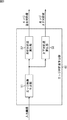
図1は、本発明を適用した画像処理装置の一実施の形態の機能構成例を示している。
[Configuration example of image processing apparatus]
FIG. 1 shows a functional configuration example of an embodiment of an image processing apparatus to which the present invention is applied.
図1の画像処理装置11は、例えば、デジタルカメラ等の撮像装置や、他の画像処理装置から入力された入力画像の線対称性を示す対称度を算出するとともに、入力画像を所定の領域に分割する分割線を検出し、対称度および分割線の少なくともいずれか一方に基づいて、入力画像の構図を、所定の構図パターンに分類する。
The
画像処理装置11は、対称度算出部31、分割線検出部32、および構図分類部33から構成される。
The
画像処理装置11に入力された入力画像は、対称度算出部31および分割線検出部32に供給される。
The input image input to the
対称度算出部31は、入力画像の左右方向および上下方向のそれぞれに対する、入力画像の画素毎の画素情報(画素値)についての線対称性を示す対称度を算出し、構図分類部33に供給する。
The degree-of-
[対称度算出部の機能構成例について]
図2は、対称度算出部31の機能構成例を示している。
[Functional configuration example of symmetry calculation unit]
FIG. 2 shows a functional configuration example of the symmetry
対称度算出部31は、エッジ対称度算出部41、色対称度算出部42、および対称度決定部43を備えている。
The
エッジ対称度算出部41は、入力画像の画素毎の画素情報の1つであるエッジ情報についての対称度(以下、エッジ対称度という)を算出し、対称度決定部43に供給する。
The edge symmetry
[エッジ対称度算出部の機能構成例について]
図3は、エッジ対称度算出部41の機能構成例を示している。
[Example of functional configuration of edge symmetry calculator]
FIG. 3 shows a functional configuration example of the edge
エッジ対称度算出部41は、エッジ画像生成部51、左右対称度算出部52、および上下対称度算出部53を備えている。
The edge
エッジ画像生成部51は、入力画像の各画素に基づいて、画素毎のエッジ情報からなるエッジ画像を生成し、左右対称度算出部52および上下対称度算出部53に供給する。
The edge
左右対称度算出部52は、エッジ画像生成部51からのエッジ画像の左右方向の中心線に対する、エッジ情報についての対称度であるエッジ左右対称度を算出し、出力する。
The left / right
上下対称度算出部53は、エッジ画像生成部51からのエッジ画像の上下方向の中心線に対する、エッジ情報についての対称度であるエッジ上下対称度を算出し、出力する。
The
このようにして、エッジ対称度算出部41は、エッジ左右対称度およびエッジ上下対称度を、エッジ対称度として、対称度決定部43に供給する。
In this way, the edge
図2の説明に戻り、色対称度算出部42は、入力画像の画素毎の画素情報の1つである色情報についての対称度(以下、色対称度という)を算出し、対称度決定部43に供給する。
Returning to the description of FIG. 2, the color
[色対称度算出部の機能構成例について]
図4は、色対称度算出部42の機能構成例を示している。
[Example of functional configuration of color symmetry calculation unit]
FIG. 4 shows a functional configuration example of the color symmetry
色対称度算出部42は、色空間変換部61、左右対称度算出部62、および上下対称度算出部63を備えている。
The color
色空間変換部61は、入力画像の各画素の画素情報(色情報)が表現される色空間を、他の色空間に変換し、変換された色空間で表現される色情報からなる入力画像を、左右対称度算出部62および上下対称度算出部63に供給する。
The color
左右対称度算出部62は、色空間変換部61からの入力画像の左右方向の中心線に対する、色情報についての対称度である色左右対称度を算出し、出力する。
The left / right
上下対称度算出部63は、色空間変換部61からの入力画像の上下方向の中心線に対する、色情報についての対称度である色上下対称度を算出し、出力する。
The
このようにして、色対称度算出部42は、色左右対称度および色上下対称度を、色対称度として、対称度決定部43に供給する。
In this way, the color symmetry
図2の説明に戻り、対称度決定部43は、エッジ対称度算出部41からのエッジ対称度、および、色対称度算出部42からの色対称度に基づいて、入力画像の左右方向に対する線対称性を示す左右対称度、および、入力画像の上下方向に対する線対称性を示す上下対称度を決定する。具体的には、対称度決定部43は、エッジ対称度算出部41からエッジ対称度として供給されてくるエッジ左右対称度と、色対称度算出部42から色対称度として供給されてくる色左右対称度のうちの、所定の条件を満たす方を左右対称度に決定する。また、対称度決定部43は、エッジ対称度算出部41からエッジ対称度として供給されてくるエッジ上下対称度と、色対称度算出部42から色対称度として供給されてくる色上下対称度のうちの、所定の条件を満たす方を上下対称度に決定する。
Returning to the description of FIG. 2, the
このようにして、対称度算出部31は、左右対称度および上下対称度を、対称度として構図分類部33に供給する。
In this way, the symmetry
図1の説明に戻り、分割線検出部32は、入力画像における画素情報の分布の変化から、入力画像を分割する分割線を検出し、検出した分割線を表す分割線情報を、構図分類部33に供給する。
Returning to the description of FIG. 1, the dividing
[分割線検出部の機能構成例について]
図5は、分割線検出部32の機能構成例を示している。
[Example of functional configuration of dividing line detector]
FIG. 5 shows a functional configuration example of the dividing
分割線検出部32は、エッジ画像生成部71、水平分割線検出部72、垂直分割線検出部73、および斜め分割線検出部74,75を備えている。
The dividing
エッジ画像生成部71は、図3のエッジ画像生成部51と同様に、入力画像の各画素に基づいて、画素毎のエッジ情報からなるエッジ画像を生成し、水平分割線検出部72乃至斜め分割線検出部75に供給する。
Similarly to the edge
水平分割線検出部72は、エッジ画像生成部71からのエッジ画像において、水平方向にエッジ情報を積算し、その積算値の分布から、入力画像を水平方向に(すなわち、上下に)分割する水平分割線を検出する。水平分割線検出部72は、検出した水平分割線を表す水平分割線情報を出力する。
The horizontal dividing
垂直分割線検出部73は、エッジ画像生成部71からのエッジ画像において、垂直方向にエッジ情報を積算し、その積算値の分布から、入力画像を垂直方向に(すなわち、左右に)分割する垂直分割線を検出する。垂直分割線検出部73は、検出した垂直分割線を表す垂直分割線情報を出力する。
The vertical dividing
斜め分割線検出部74は、エッジ画像生成部71からのエッジ画像において、右上斜め方向にエッジ情報を積算し、その積算値の分布から、入力画像を右上斜め方向に分割する右上斜め分割線を検出する。斜め分割線検出部74は、検出した右上斜め分割線を表す第1の斜め分割線情報を出力する。
The oblique dividing
斜め分割線検出部75は、エッジ画像生成部71からのエッジ画像において、左上斜め方向にエッジ情報を積算し、その積算値の分布から、入力画像を左上斜め方向に分割する左上斜め分割線を検出する。斜め分割線検出部75は、検出した左上斜め分割線を表す第2の斜め分割線情報を出力する。
The oblique dividing
このようにして、分割線検出部32は、水平分割線情報、垂直分割線情報、第1の斜め分割線情報、および第2の斜め分割線情報を、分割線情報として構図分類部33に供給する。
In this way, the dividing
ここで、図6乃至8を参照して、水平分割線検出部72乃至斜め分割線検出部75の機能構成例を示している。
Here, with reference to FIGS. 6 to 8, functional configuration examples of the horizontal dividing
[水平分割線検出部の機能構成例について]
図6は、水平分割線検出部72の機能構成例を示している。
[Functional configuration example of horizontal dividing line detector]
FIG. 6 shows a functional configuration example of the horizontal
水平分割線検出部72は、水平方向積算部111、LPF(Low Pass Filter)112、ピーク値検出部113、および閾値処理部114を備えている。
The horizontal dividing
水平方向積算部111は、エッジ画像生成部71からのエッジ画像において、水平方向の画素のライン(以下、単にラインという)毎に、画素の画素情報(エッジ情報)を積算し、その積算結果をLPF112に供給する。ここで得られる積算結果は、エッジ画像(入力画像)の垂直方向の画素位置に対する、水平方向のエッジ情報の積算値となる。
The
LPF112は、水平方向積算部111からの積算結果、すなわち、エッジ画像の垂直方向の画素位置に対する水平方向のエッジ情報の積算値に対してフィルタリング処理を施すことにより、積算結果のノイズ除去を行い、ピーク値検出部113に供給する。
The
ピーク値検出部113は、LPF112によりノイズ除去された積算結果において、積算値のピーク値を検出し、検出したピーク値と、そのピーク値となる積算値が得られた水平方向のラインの垂直方向の画素位置とを、閾値処理部114に供給する。
The
閾値処理部114は、ピーク値検出部113からのピーク値と、所定の閾値とを比較し、ピーク値が所定の閾値より大きい場合、そのピーク値となる積算値が得られた水平方向のラインを水平分割線とし、エッジ画像におけるそのラインの垂直方向の画素位置を、水平分割線情報として出力する。
The threshold
[垂直分割線検出部の機能構成例について]
図7は、垂直分割線検出部73の機能構成例を示している。
[Functional configuration example of vertical dividing line detector]
FIG. 7 shows a functional configuration example of the vertical dividing
垂直分割線検出部73は、垂直方向積算部121、LPF122、ピーク値検出部123、および閾値処理部124を備えている。
The vertical dividing
垂直方向積算部121は、エッジ画像生成部71からのエッジ画像において、垂直方向のライン毎にエッジ情報を積算し、その積算結果をLPF122に供給する。ここで得られる積算結果は、エッジ画像(入力画像)の水平方向の画素位置に対する、垂直方向のエッジ情報の積算値となる。
The
LPF122は、垂直方向積算部121からの積算結果、すなわち、エッジ画像の水平方向の画素位置に対する垂直方向のエッジ情報の積算値に対してフィルタリング処理を施すことにより、積算結果のノイズ除去を行い、ピーク値検出部123に供給する。
The
ピーク値検出部123は、LPF122によりノイズ除去された積算結果において、積算値のピーク値を検出し、検出したピーク値と、そのピーク値となる積算値が得られた垂直方向のラインの水平方向の画素位置とを、閾値処理部124に供給する。
The peak
閾値処理部124は、ピーク値検出部123からのピーク値と、所定の閾値とを比較し、ピーク値が所定の閾値より大きい場合、そのピーク値となる積算値が得られた水平方向のラインを垂直分割線とし、エッジ画像におけるそのラインの水平方向の画素位置を、垂直分割線情報として出力する。
The
[斜め分割線検出部の機能構成例について]
図8は、斜め分割線検出部74の機能構成例を示している。
[Example of functional configuration of diagonal dividing line detector]
FIG. 8 shows a functional configuration example of the oblique dividing
斜め分割線検出部74は、斜め方向積算部131、LPF132、ピーク値検出部133、および閾値処理部134を備えている。
The oblique dividing
斜め方向積算部131は、エッジ画像生成部71からのエッジ画像において、右上斜め方向のライン毎にエッジ情報を積算し、その積算結果をLPF132に供給する。ここで得られる積算結果は、エッジ画像(入力画像)の左上斜め方向の画素位置に対する、右上斜め方向のエッジ情報の積算値となる。
The oblique
LPF132は、斜め方向積算部131からの積算結果、すなわち、エッジ画像の左上斜め方向の画素位置に対する右上斜め方向のエッジ情報の積算値に対してフィルタリング処理を施すことにより、積算結果のノイズ除去を行い、ピーク値検出部133に供給する。
The
ピーク値検出部133は、LPF132によりノイズ除去された積算結果において、積算値のピーク値を検出し、検出したピーク値と、そのピーク値となる積算値が得られた右上斜め方向のラインの左上斜め方向の画素位置とを、閾値処理部134に供給する。
The peak
閾値処理部134は、ピーク値検出部133からのピーク値と、所定の閾値とを比較し、ピーク値が所定の閾値より大きい場合、そのピーク値となる積算値が得られた右上斜め方向のラインを右上斜め分割線とし、エッジ画像におけるそのラインについての、左上斜め方向の画素位置を、第1の分割線情報として出力する。
The threshold
なお、斜め分割線検出部75の機能構成例は、図8の斜め分割線検出部74の各部において、エッジ情報の右上斜め方向に対する処理が、左上斜め方向に対する処理に代わる以外は、基本的に同様であるので、その説明は省略する。
The functional configuration example of the oblique dividing
さて、図1の説明に戻り、構図分類部33は、対称度算出部31からの対称度、および、分割線検出部32からの分割線情報に基づいて、入力画像の構図を、予め決められている構図パターンのいずれかに分類し、その構図パターンを、対称度および分割線情報とともに、図示せぬ情報処理装置や記憶装置等に出力する。
Now, returning to the description of FIG. 1, the
[画像処理装置の構図分類処理について]
次に、図9のフローチャートを参照して、図1の画像処理装置11の構図分類処理について説明する。
[Composition classification processing of image processing apparatus]
Next, the composition classification process of the
図9のフローチャートで示される構図分類処理によって、画像処理装置11に入力される入力画像の構図は、予め決められている構図パターンのいずれかに分類される。
The composition of the input image input to the
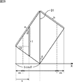
ここで、図10を参照して、写真撮影などにおいて一般的に推奨される構図パターンについて説明する。 Here, with reference to FIG. 10, a composition pattern generally recommended in photography and the like will be described.
図10に示される構図パターンCには、3分割構図と対角線構図の2つの代表的な構図パターンが含まれている。 The composition pattern C shown in FIG. 10 includes two typical composition patterns, a three-part composition and a diagonal composition.
3分割構図は、3分割線と呼ばれる、水平分割線H1,H2および垂直分割線V1,V2からなる構図であり、水平分割線H1,H2および垂直分割線V1,V2の少なくともいずれか1つの線上に、被写体や風景の境界を合わせたり、水平分割線H1,H2と垂直分割線V1,V2との4つの交点(3分割線交点)のいずれかに被写体を合わせることで、バランスのとれた画像が得られるようになる。 The three-division composition is a composition composed of horizontal division lines H1 and H2 and vertical division lines V1 and V2, which are called three-division lines, on at least one of the horizontal division lines H1 and H2 and the vertical division lines V1 and V2. A well-balanced image by aligning the boundary of the subject and the landscape, or by aligning the subject at one of the four intersections of the horizontal dividing lines H1, H2 and the vertical dividing lines V1, V2 (three dividing line intersections) Can be obtained.
また、対角線構図は、対角線D1,D2からなる構図であり、対角線D1,D2の少なくともいずれか1つの線上に、被写体や風景の境界を合わせることで、バランスのとれた画像が得られるようになる。 The diagonal composition is composed of diagonal lines D1 and D2, and a balanced image can be obtained by aligning the boundary between the subject and the landscape on at least one of the diagonal lines D1 and D2. .
以下において説明する構図分類処理においては、入力画像の構図が、左右方向または上下方向に対してどの程度の線対称性を有するか、または、上述した3分割構図や対角線構図のうちのいずれに近似しているかが判別される。 In the composition classification process described below, the composition of an input image has a degree of line symmetry with respect to the horizontal direction or the vertical direction, or approximates any of the above-described three-part composition and diagonal composition. Is determined.
図9のフローチャートのステップS11において、対称度算出部31は、対称度算出処理を実行し、入力画像の左右方向および上下方向のそれぞれに対する、入力画像の画素毎の画素情報についての対称度を算出する。
In step S11 of the flowchart of FIG. 9, the symmetry
[対称度算出部の対称度算出処理について]
ここで、図11のフローチャートを参照して、図9のフローチャートのステップS11における対称度算出処理について説明する。
[Symmetry calculation process of symmetry calculation unit]
Here, with reference to the flowchart of FIG. 11, the symmetry calculation processing in step S <b> 11 of the flowchart of FIG. 9 will be described.
ステップS31において、対称度算出部31のエッジ対称度算出部41は、エッジ対称度算出処理を実行し、入力画像のエッジ対称度を算出する。
In step S31, the edge
[エッジ対称度算出部のエッジ対称度算出処理について]
ここで、図12のフローチャートを参照して、図11のフローチャートのステップS31におけるエッジ対称度算出処理について説明する。
[About Edge Symmetry Calculation Processing of Edge Symmetry Calculation Unit]
Here, the edge symmetry calculation processing in step S31 of the flowchart of FIG. 11 will be described with reference to the flowchart of FIG.
ステップS41において、エッジ対称度算出部41のエッジ画像生成部51は、入力画像から輝度画像を取得し、その輝度画像に対してSobelフィルタや、Gaborフィルタなどのエッジ抽出フィルタを適用することで得られるエッジ値(エッジ情報)からなるエッジ画像を生成する。
In step S41, the edge
また、エッジ画像生成部51は、入力画像からR,G,B等の色チャネル画像を取得し、色チャネル画像それぞれに対してエッジ抽出フィルタを適用することで得られるエッジ値をチャネル間で画素毎に比較し、それぞれの最大値からなるエッジ画像を生成するようにしてもよい。
The edge
さらに、エッジ画像生成部51は、入力画像に対して、平均シフトアルゴリズム(Mean Shift法)等を用いた色の領域分割を行い、分割された領域の境界線上の画素に対して、エッジ値を与えることで、エッジ画像を生成するようにもできる。この場合、例えば、領域の境界線上の画素に対しては1のエッジ値を、それ以外の領域の画素には0のエッジ値を与える。
Further, the edge
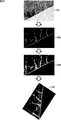
例えば、図13に示されるように、被写体が山である風景画像が入力画像P1として入力された場合、エッジ画像生成部51により、山を含む風景の輪郭形状を表すエッジ画像P1eが生成される。このようにして生成されたエッジ画像P1eは、左右対称度算出部52および上下対称度算出部53に供給される。
For example, as illustrated in FIG. 13, when a landscape image whose subject is a mountain is input as the input image P1, the edge
ステップS42において、左右対称度算出部52は、エッジ画像生成部51からのエッジ画像に基づいて、エッジ画像の左右対称度であるエッジ左右対称度を算出する。
In step S <b> 42, the left / right
ここで、図14を参照して、エッジ左右対称度の算出の例について説明する。図14は、エッジ画像P1eを示している。 Here, with reference to FIG. 14, an example of calculating the edge symmetry will be described. FIG. 14 shows an edge image P1e.
図14に示されるように、エッジ画像P1eが、H×W画素から構成されるものとすると、エッジ画像P1eの左右方向の中心線は、画素位置W/2のラインとなる。 As shown in FIG. 14, if the edge image P1e is composed of H × W pixels, the center line in the left-right direction of the edge image P1e is a line at the pixel position W / 2.
また、上下方向の画素位置iとなる水平方向のラインに注目し、左右方向の中心線上の画素(画素位置W/2の画素)から右側にj個目の画素の画素位置を+jで表し、左側にj個目の画素の画素位置を−jで表すものとする。 Also, paying attention to the horizontal line that is the vertical pixel position i, the pixel position of the jth pixel on the right side from the pixel on the center line in the horizontal direction (pixel at pixel position W / 2) is represented by + j, The pixel position of the jth pixel on the left side is represented by -j.
このとき、エッジ画像P1eにおいて、左右方向の中心線(画素位置W/2)を挟んで対となる、画素位置(i,j)および(i,-j)(以下、単に画素位置(i,j)という)の画素同士のエッジ情報の差分の総和d、左右方向の中心線を挟んで対となる画素のエッジ情報の総和(すなわち、全画素のエッジ情報の総和)sは、それぞれ以下の式(1),(2)で表される。 At this time, in the edge image P1e, pixel positions (i, j) and (i, -j) (hereinafter simply referred to as pixel positions (i, j)) and the sum d of differences in edge information between pixels, and the sum of edge information of pixels paired across the center line in the left-right direction (that is, the sum of edge information of all pixels) s It is expressed by equations (1) and (2).

式(1),(2)において、係数wは、エッジ画像の中心から注目画素の画素位置(i,j)が、入力画像の中心点から離れるほど重み付けが低くなる重み係数であり、入力画像の中心点から画素位置(i,j)までの距離をrで表わすと、以下の式(3)で表わされる。 In Expressions (1) and (2), the coefficient w is a weighting coefficient whose weighting decreases as the pixel position (i, j) of the target pixel moves away from the center point of the input image from the center of the edge image. If the distance from the center point to the pixel position (i, j) is represented by r, it is represented by the following equation (3).
なお、式(3)における定数σは、任意に設定される値とする。 Note that the constant σ in Equation (3) is an arbitrarily set value.
式(1)で表わされる「エッジ情報の差分の総和」dは、エッジ画像P1eが左右対称であるほど0に近い値をとり、エッジ画像P1eが左右非対称であるほど、「エッジ情報の総和」sに近づく値をとる。そこで、エッジ画像の左右対称度であるエッジ左右対称度sym_edg_LRは、以下の式(4)で表わされるようになる。 The “total sum of edge information differences” d expressed by the equation (1) takes a value closer to 0 as the edge image P1e is left-right symmetric, and the “total sum of edge information” as the edge image P1e is left-right asymmetric. Take a value approaching s. Therefore, the edge symmetry degree sym_edg_LR, which is the degree of symmetry of the edge image, is expressed by the following equation (4).
![]()
![]()
すなわち、エッジ左右対称度sym_edg_LRは、0<sym_edg_LR≦1の範囲の値をとり、エッジ画像P1eが左右対称であるほど1に近い値をとる。 That is, the edge left-right symmetry degree sym_edg_LR takes a value in a range of 0 <sym_edg_LR ≦ 1, and takes a value closer to 1 as the edge image P1e is left-right symmetric.
このようにして、エッジ左右対称度が算出される。 In this way, the edge right / left symmetry is calculated.
図12のフローチャートに戻り、ステップS43において、上下対称度算出部53は、エッジ画像生成部51からのエッジ画像に基づいて、エッジ画像の上下対称度であるエッジ上下対称度を算出する。
Returning to the flowchart of FIG. 12, in step S <b> 43, the
なお、エッジ上下対称度sym_edg_TBは、図15に示されるように、エッジ画像P1eの上下方向の中心線を、画素位置H/2のラインとして、左右方向の画素位置jとなる垂直方向の画素のラインに注目し、上下方向の中心線上の画素(画素位置H/2の画素)から下側にi個目の画素の画素位置を+iで表し、上側にi個目の画素の画素位置を−iで表すものとすると、式(1),(2)において値Hと値Wを入れ替えることにより、エッジ左右対称度sym_edg_LRと同様にして算出される。 As shown in FIG. 15, the edge vertical symmetry sym_edg_TB is obtained by using the vertical center line of the edge image P1e as the line at the pixel position H / 2, and the vertical pixel position j as the horizontal pixel position j. Paying attention to the line, the pixel position of the i-th pixel from the pixel on the center line in the vertical direction (pixel at pixel position H / 2) is represented by + i, and the pixel position of the i-th pixel is represented by − Assuming that i is expressed by i, the value H and the value W are interchanged in the expressions (1) and (2), and the calculation is performed in the same manner as the edge left-right symmetry sym_edg_LR.
このようにして、エッジ上下対称度が算出される。 In this way, the edge vertical symmetry is calculated.
ステップS43の後、処理は、図11のフローチャートのステップS31に戻り、ステップS32に進む。 After step S43, the process returns to step S31 in the flowchart of FIG. 11 and proceeds to step S32.
ところで、入力画像として、図16の左側に示されるような、被写体として略同一の形状をした色の異なる野菜が左右に並んでいる入力画像P2が入力された場合、エッジ対称度算出処理においては、図16の右側に示されるようなエッジ画像P2eが生成される By the way, when an input image P2 is input as an input image, as shown on the left side of FIG. The edge image P2e as shown on the right side of FIG. 16 is generated.
図16のエッジ画像P2eは、左右方向に対する線対称性が高いので、エッジ左右対称度として大きい値が得られるが、実際の入力画像P2においては、左右に並んだ被写体の色が異なるので、決して左右方向に対する線対称性が高いとは言えない。 Since the edge image P2e in FIG. 16 has a high line symmetry in the left-right direction, a large value can be obtained as the edge left-right symmetry. However, in the actual input image P2, the colors of the subjects arranged in the left and right are different. It cannot be said that the line symmetry with respect to the left-right direction is high.
このように、エッジ対称度算出処理では、入力画像の色についての線対称性を求めることはできない。 Thus, in the edge symmetry calculation process, the line symmetry for the color of the input image cannot be obtained.
そこで、ステップS32において、色対称度算出部42は、色対称度算出処理を実行し、入力画像の色対称度を算出することで、入力画像の色についての線対称性を求める。
Therefore, in step S32, the color
[色対称度算出部の色対称度算出処理について]
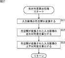
ここで、図17のフローチャートを参照して、図11のフローチャートのステップS31における色対称度算出処理について説明する。
[About color symmetry calculation processing of the color symmetry calculation unit]
Here, with reference to the flowchart of FIG. 17, the color symmetry degree calculation process in step S31 of the flowchart of FIG. 11 will be described.
ステップS51において、色空間変換部61は、例えば、RGB空間で表現される入力画像の各画素を、L*a*b*空間で表現されるように、色空間を変換する。色空間変換部61は、L*a*b*空間で表現される入力画像を、左右対称度算出部62および上下対称度算出部63に供給する。
In step S51, the color
ステップS52において、左右対称度算出部62は、色空間変換部61によって色空間が変換され、L*a*b*空間で表現される入力画像の左右対称度である色左右対称度を算出する。
In step S <b> 52, the left / right
ここで、色左右対称度の算出の例について説明する。 Here, an example of calculating the color left-right symmetry will be described.
なお、L*a*b*空間で表現される入力画像は、図14で説明したエッジ画像P1eと同様に表されるものとする。 Note that the input image expressed in the L * a * b * space is expressed in the same manner as the edge image P1e described in FIG.
このとき、入力画像において、左右方向の中心線(画素位置W/2)を挟んで対となる画素位置(i,j)の画素同士の色差の総和Dは、以下の式(5)で表される。 At this time, in the input image, the sum D of the color differences between the pixels at the pixel position (i, j) paired across the center line (pixel position W / 2) in the left-right direction is expressed by the following equation (5). Is done.
式(5)において、画素位置(i,j)の画素同士の色差dE、L*軸成分Lの差分dL、a*軸成分aの差分da、および、b*軸成分bの差分dbは、それぞれ、以下の式(6)のように表される。 In Expression (5), the color difference dE between the pixels at the pixel position (i, j), the difference dL of the L * axis component L, the difference da of the a * axis component a, and the difference db of the b * axis component b are: Each is expressed as the following equation (6).
また、式(5)における係数wは、画素位置(i,j)の画素同士の色差dEに係る重み係数であり、以下の式(7)で表わされる。 In addition, the coefficient w in Expression (5) is a weighting coefficient related to the color difference dE between the pixels at the pixel position (i, j), and is expressed by Expression (7) below.
![]()
![]()
式(7)において、重み係数wpは、画素位置(i,j)が、入力画像の中心点から離れるほど重み付けが低くなる重み係数であり、以下の式(8)で表わされる。 In Expression (7), the weighting coefficient w p is a weighting coefficient that decreases in weight as the pixel position (i, j) moves away from the center point of the input image, and is expressed by Expression (8) below.
なお、式(8)のおける定数βは、任意に設定される値とする。 Note that the constant β in the equation (8) is a value set arbitrarily.
また、式(7)において、重み係数wEは、注目画素位置(i,j)の画素同士の色差dEが大きい領域ほど重み付けが高くなる重み係数であり、図18のような特性を有する。具体的には、重み係数wEは、色差dEが値dE1より小さい場合には1.0をとり、値dE2より大きい場合にはwEMをとる。なお、色差dEが値dE1乃至dE2のときには、色差dEの増加に応じて、重み係数wEも増加する。 Also has the formula (7), the weight coefficient w E is focused pixel position (i, j) is a pixel weighting coefficient weighting as region color difference dE is greater increases between the, the characteristics as shown in FIG. 18. Specifically, the weighting factor w E takes 1.0 if the color difference dE value dE 1 less than in the case greater than the value dE 2 take w EM. When the color difference dE is a value dE 1 to dE 2 , the weight coefficient w E increases as the color difference dE increases.
すなわち、重み係数wEによれば、図16の入力画像P2のように、左右で大きく色が異なる領域に対して、色差dEをより強調するように、色差dEに対して重み付けされる。 That is, according to the weighting coefficient w E, as the input image P2 in FIG. 16, large color left and right with respect to different regions, so as to more emphasize the color difference dE, is weighted to the color difference dE.
したがって、式(5)で表わされる「色差の総和」Dは、入力画像の色が左右対称であるほど小さい値をとり、入力画像の色が左右非対称であるほど大きい値をとるが、扱いを簡便にするために、図19に示されるように変換する。 Therefore, the “sum of color differences” D represented by the equation (5) takes a smaller value as the color of the input image is symmetric, and takes a larger value as the color of the input image is asymmetrical. For simplicity, conversion is performed as shown in FIG.
すなわち、図19によれば、変換後の色差の総和D’は、色差の総和Dが、画素位置(i,j)の画素同士の色差dEの最小値dEminより小さい場合には0をとり、画素位置(i,j)の画素同士の色差dEの最大値dEmaxより大きい場合には1をとる。なお、色差の総和Dが、dEmin乃至dEmaxのときは、色差の総和Dの増加に応じて、変換後の色差の総和D’も増加する。 That is, according to FIG. 19, the total color difference sum D ′ after conversion is 0 when the color difference sum D is smaller than the minimum value dE min of the color difference dE between the pixels at the pixel position (i, j). When the maximum value dE max of the color difference dE between the pixels at the pixel position (i, j) is larger, 1 is taken. When the sum D of color differences is dE min to dE max , the sum D ′ of color differences after conversion increases as the sum D of color differences increases.
そして、入力画像の色についての左右対称度である色左右対称度sym_col_LRは、以下の式(9)で表わされるようになる。 A color symmetry degree sym_col_LR, which is a degree of symmetry with respect to the color of the input image, is expressed by the following equation (9).
![]()
![]()
すなわち、色左右対称度sym_col_LRは、0≦sym_col_LR≦1の範囲の値をとり、入力画像の色が左右対称であるほど1に近い値をとる。 That is, the color symmetry degree sym_col_LR takes a value in the range of 0 ≦ sym_col_LR ≦ 1, and takes a value closer to 1 as the color of the input image is symmetrical.
このようにして、色左右対称度が算出される。 In this way, the color left / right symmetry is calculated.
図17のフローチャートに戻り、ステップS53において、上下対称度算出部63は、色空間変換部61によって色空間が変換され、L*a*b*空間で表現される入力画像の上下対称度である色上下対称度を算出する。
Returning to the flowchart of FIG. 17, in step S <b> 53, the vertical
なお、色上下対称度sym_col_TBは、図15で説明したエッジ画像P1eと同様にして、入力画像の上下方向の中心線を、画素位置H/2のラインとして、左右方向の画素位置jとなる垂直方向のラインに注目し、上下方向の中心線上の画素(画素位置H/2の画素)から下側にi個目の画素の画素位置を+iで表し、上側にi個目の画素の画素位置を−iで表すものとすると、式(5),(6)において値Hと値Wを入れ替えることにより、色左右対称度sym_col_LRと同様にして算出される。 Note that the color vertical symmetry degree sym_col_TB is the same as the edge image P1e described in FIG. 15, and the vertical center line of the input image is the pixel position H / 2 and the vertical pixel position j is the vertical pixel position j. Paying attention to the direction line, the pixel position of the i-th pixel is represented by + i on the lower side from the pixel on the center line in the vertical direction (pixel at pixel position H / 2), and the pixel position of the i-th pixel on the upper side Is represented by −i, it is calculated in the same manner as the color left-right symmetry sym_col_LR by exchanging the value H and the value W in the equations (5) and (6).
このようにして、色上下対称度が算出される。 In this way, the color vertical symmetry degree is calculated.
ステップS53の後、処理は、図11のフローチャートのステップS32に戻り、ステップS33に進む。 After step S53, the process returns to step S32 in the flowchart of FIG. 11 and proceeds to step S33.
ステップS33において、対称度決定部43は、エッジ対称度算出部41からのエッジ対称度、および、色対称度算出部42からの色対称度に基づいて、入力画像の左右対称度および上下対称度を決定する。
In step S <b> 33, the
例えば、対称度決定部43は、エッジ対称度算出部41からのエッジ左右対称度と、色対称度算出部42からの色左右対称度のうちの小さい方を左右対称度に決定する。同様に、対称度決定部43は、エッジ対称度算出部41からのエッジ上下対称度と、色対称度算出部42からの色上下対称度のうちの小さい方を上下対称度に決定する。
For example, the
また、対称度決定部43は、エッジ左右対称度と色左右対称度のうちの大きい方を左右対称度に決定し、エッジ上下対称度と色上下対称度のうちの大きい方を上下対称度に決定するようにしてもよい。
Further, the
対称度算出部31は、このようにして決定した左右対称度および上下対称度を、対称度として構図分類部33に供給し、処理は図9のステップS11に戻る。
The degree-of-
ステップS11の後、ステップS12において、分割線検出部32は、分割線検出処理を実行し、入力画像における画素情報の分布の変化から分割線を検出する。
After step S11, in step S12, the parting
[分割線検出部の分割線検出処理について]
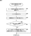
ここで、図20のフローチャートを参照して、図9のフローチャートのステップS12における分割線検出処理について説明する。
[About the dividing line detection processing of the dividing line detection unit]
Here, the dividing line detection process in step S12 of the flowchart of FIG. 9 will be described with reference to the flowchart of FIG.
ステップS71において、分割線検出部32のエッジ画像生成部71は、図12のフローチャートのステップS41の処理と同様に、入力画像から輝度画像を取得し、その輝度画像に対してSobelフィルタや、Gaborフィルタなどのエッジ抽出フィルタを適用することで得られるエッジ値(エッジ情報)からなるエッジ画像を生成する。
In step S71, the edge
また、エッジ画像生成部71は、入力画像からR,G,B等の色チャネル画像を取得し、色チャネル画像それぞれに対してエッジ抽出フィルタを適用することで得られるエッジ値をチャネル間で画素毎に比較し、それぞれの最大値からなるエッジ画像を生成するようにしてもよい。
Further, the edge
さらに、エッジ画像生成部71は、入力画像に対して、平均シフトアルゴリズム(Mean Shift法)等を用いた色の領域分割を行い、分割された領域の境界線上の画素に対して、エッジ値を与えることで、エッジ画像を生成するようにもできる。この場合、例えば、領域の境界線上の画素に対しては1のエッジ値を、それ以外の領域の画素には0のエッジ値を与える。
Further, the edge
例えば、図21に示されるように、地平線を含む風景画像が入力画像P3として入力された場合、エッジ画像生成部71により、その風景の輪郭形状を表すエッジ画像P3eが生成される。このようにして生成されたエッジ画像P3eは、水平分割線検出部72乃至斜め分割線検出部75に供給される。
For example, as shown in FIG. 21, when a landscape image including a horizon is input as the input image P3, the edge
ステップS72において、水平分割線検出部72は、水平分割線検出処理を実行し、エッジ画像生成部71からのエッジ画像に基づいて、入力画像を水平方向に(すなわち、上下に)分割する水平分割線を検出する。
In step S72, the horizontal dividing
[水平分割線検出部の水平分割線検出処理について]
ここで、図22のフローチャートを参照して、図20のフローチャートのステップS72における水平分割線検出処理について説明する。
[Horizontal dividing line detection processing of the horizontal dividing line detector]
Here, the horizontal dividing line detection processing in step S72 of the flowchart of FIG. 20 will be described with reference to the flowchart of FIG.
ステップS81において、水平分割線検出部72の水平方向積算部111は、エッジ画像生成部71からのエッジ画像において、水平方向のライン毎にエッジ情報を積算し、その積算結果をLPF112に供給する。
In step S <b> 81, the horizontal
なお、水平方向積算部111は、エッジ情報を積算する際に、各画素のエッジ情報に対して、上述の式(3)で示したような重み係数wにより重み付けした後に積算するようにしてもよい。これにより、エッジ画像の中心から離れた積算値ほど、その値が小さくなるようになる。
In addition, when integrating the edge information, the horizontal
ここで得られる積算結果は、エッジ画像(入力画像)の垂直方向の画素位置に対する、水平方向のエッジ情報の積算値となり、図23に示されるグラフにおいて、黒塗りのひし形のプロットで表わされる。 The integration result obtained here is an integration value of edge information in the horizontal direction with respect to the pixel position in the vertical direction of the edge image (input image), and is represented by a black diamond plot in the graph shown in FIG.
図23は、水平分割線検出処理により求められる、エッジ情報の水平方向の積算値、およびその積算値に対して後述する演算を施した値の例を示している。 FIG. 23 shows an example of the horizontal direction integrated value of edge information obtained by the horizontal dividing line detection process and a value obtained by performing an operation described later on the integrated value.
図23のグラフにおいて、横軸は、エッジ画像(入力画像)の垂直方向の画素位置を表している。 In the graph of FIG. 23, the horizontal axis represents the pixel position in the vertical direction of the edge image (input image).
さて、ステップS82において、LPF112は、水平方向積算部111からのエッジ情報の積算値に対して、フィルタリング処理を施すことによりノイズ除去を行い、ピーク値検出部113に供給する。図23において、ノイズ除去された積算結果は、白抜きの正方形のプロットで示される。
In step S <b> 82, the
ステップS83において、ピーク値検出部113は、LPF112によりノイズ除去された積算結果において、積算値のピーク値を検出する。
In step S <b> 83, the peak
具体的には、ピーク値検出部113は、ノイズ除去された積算値の1次微分値(図23中、白抜きの三角形のプロット)を求め、さらに、その絶対値である1次微分絶対値(図23中、バツ印のプロット)を求める。ピーク値検出部113は、1次微分値が負の値をとり、かつ、極大値をとる1次微分絶対値(図23中、破線の丸印で囲まれる点)に対応する積算値(図23中、実線の丸印で囲まれる点)を、積算値のピーク値とする。これにより、積算値において、急峻に変化しているピーク値が検出されるようになる。
Specifically, the peak
ピーク値検出部113は、検出したピーク値と、そのピーク値となる積算値が得られた水平方向のラインの垂直方向の画素位置(図23の例では、画素位置7)とを、閾値処理部114に供給する。
The peak
ステップS84において、閾値処理部114は、ピーク値検出部113からのピーク値と、所定の閾値とを比較し、ピーク値が所定の閾値より大きいか否かを判定する。
In step S84, the threshold
ステップS84において、ピーク値が所定の閾値より大きいと判定された場合、処理はステップS85に進み、閾値処理部114は、そのピーク値となる積算値が得られた水平方向のライン(垂直方向の画素位置7のライン)を水平分割線とする。また、閾値処理部114は、エッジ画像におけるそのラインの垂直方向の画素位置を、水平分割線情報として出力して、水平分割線検出処理は終了する。その後、処理は、図20のステップS72に戻る。
If it is determined in step S84 that the peak value is greater than the predetermined threshold value, the process proceeds to step S85, and the threshold
このようにして、図21に示されたような入力画像P3が入力された場合、図24に示されるように、入力画像P3における地平線部分における水平方向のラインが、水平分割線として検出される。 In this way, when the input image P3 as shown in FIG. 21 is input, as shown in FIG. 24, the horizontal line in the horizon portion in the input image P3 is detected as a horizontal dividing line. .
一方、ステップS84において、ピーク値が所定の閾値より大きくないと判定された場合、ステップS85の処理はスキップされる。この場合、水平分割線は検出されずに、水平分割線検出処理は終了する。その後、処理は、図20のステップS72に戻る。 On the other hand, if it is determined in step S84 that the peak value is not greater than the predetermined threshold value, the process in step S85 is skipped. In this case, the horizontal dividing line detection process ends without detecting the horizontal dividing line. Thereafter, the processing returns to step S72 in FIG.
ステップS72の後、ステップS73において、垂直分割線検出部73は、垂直分割線検出処理を実行し、エッジ画像生成部71からのエッジ画像に基づいて、入力画像を垂直方向に(すなわち、左右に)分割する垂直分割線を検出する。
After step S72, in step S73, the vertical dividing
[垂直分割線検出部の垂直分割線検出処理について]
ここで、図25のフローチャートを参照して、図20のフローチャートのステップS73における垂直分割線検出処理について説明する。
[Vertical dividing line detection processing of the vertical dividing line detector]
Here, the vertical dividing line detection process in step S73 of the flowchart of FIG. 20 will be described with reference to the flowchart of FIG.
ステップS91において、垂直分割線検出部73の垂直方向積算部121は、エッジ画像生成部71からのエッジ画像において、垂直方向のライン毎にエッジ情報を積算し、その積算結果をLPF122に供給する。
In step S <b> 91, the vertical
なお、垂直方向積算部121は、エッジ情報を積算する際に、各画素のエッジ情報に対して、上述の式(3)で示したような重み係数wにより重み付けした後に積算するようにしてもよい。これにより、エッジ画像の中心から離れた積算値ほど、その値が小さくなるようになる。
In addition, when integrating the edge information, the vertical
ここで得られる積算結果は、エッジ画像(入力画像)の水平方向の画素位置に対する、垂直方向のエッジ情報の積算値となり、図26に示されるグラフにおいて、黒塗りのひし形のプロットで表わされる。 The integration result obtained here is an integrated value of the edge information in the vertical direction with respect to the pixel position in the horizontal direction of the edge image (input image), and is represented by a black diamond plot in the graph shown in FIG.
図26は、垂直分割線検出処理により求められる、エッジ情報の垂直方向の積算値、およびその積算値に対して後述する演算を施した値の例を示している。 FIG. 26 shows an example of the integrated value in the vertical direction of the edge information obtained by the vertical dividing line detection process, and a value obtained by performing an operation described later on the integrated value.
図26のグラフにおいて、横軸は、エッジ画像(入力画像)の水平方向の画素位置を表している。 In the graph of FIG. 26, the horizontal axis represents the pixel position in the horizontal direction of the edge image (input image).
さて、ステップS92において、LPF122は、垂直方向積算部121からのエッジ情報の積算値に対して、フィルタリング処理を施すことによりノイズ除去を行い、ピーク値検出部123に供給する。図26において、ノイズ除去された積算結果は、白抜きの正方形のプロットで示される。
In step S <b> 92, the
ステップS93において、ピーク値検出部123は、LPF122によりノイズ除去された積算結果において、積算値のピーク値を検出する。
In step S <b> 93, the peak
具体的には、ピーク値検出部113は、ノイズ除去された積算値の1次微分値(図26中、白抜きの三角形のプロット)を求め、さらに、その絶対値である1次微分絶対値(図26中、バツ印のプロット)を求める。ピーク値検出部123は、1次微分値が負の値をとり、かつ、極大値をとる1次微分絶対値に対応する積算値を、積算値のピーク値とする。図26においては、図23の例のように急峻に変化しているピーク値は見られないが、水平方向の画素位置11において、ピーク値となる積算値が得られる。
Specifically, the peak
ピーク値検出部123は、検出したピーク値と、そのピーク値となる積算値が得られた垂直方向のラインの水平方向の画素位置(図26の例では、画素位置11)とを、閾値処理部124に供給する。
The peak
ステップS94において、閾値処理部124は、ピーク値検出部123からのピーク値と、所定の閾値とを比較し、ピーク値が所定の閾値より大きいか否かを判定する。
In step S94, the threshold
ステップS94において、ピーク値が所定の閾値より大きいと判定された場合、処理はステップS95に進み、閾値処理部124は、そのピーク値となる積算値が得られた垂直方向のラインを垂直分割線とする。また、閾値処理部124は、エッジ画像におけるそのラインについての、水平方向の画素位置を、垂直分割線情報として出力して、垂直分割線検出処理は終了する。その後、処理は、図20のステップS73に戻る。
If it is determined in step S94 that the peak value is larger than the predetermined threshold value, the process proceeds to step S95, and the threshold
一方、ステップS94において、ピーク値が所定の閾値より大きくないと判定された場合、ステップS95の処理はスキップされる。例えば、図26におけるピーク値が所定の閾値より小さい場合、垂直分割線は検出されずに、垂直分割線検出処理は終了する。その後、処理は、図20のステップS73に戻る。 On the other hand, if it is determined in step S94 that the peak value is not greater than the predetermined threshold value, the process in step S95 is skipped. For example, if the peak value in FIG. 26 is smaller than a predetermined threshold, the vertical dividing line is not detected and the vertical dividing line detection process ends. Thereafter, the processing returns to step S73 in FIG.
ステップS73の後、ステップS74において、斜め分割線検出部74は、斜め分割線検出処理1を実行し、エッジ画像生成部71からのエッジ画像に基づいて、入力画像を右上斜め方向に分割する第1の斜め分割線を検出する。
After step S73, in step S74, the oblique dividing
[斜め分割線検出部の斜め分割線検出処理について]
ここで、図27のフローチャートを参照して、図20のフローチャートのステップS74における斜め分割線検出処理1について説明する。
[About the diagonal dividing line detection process of the diagonal dividing line detection unit]
Here, with reference to the flowchart of FIG. 27, the oblique dividing
ここで、図28の一番上に示されるように、右上から左下への山の斜面を含む風景画像が入力画像P4として入力されたとすると、エッジ画像生成部71により、図28の上から2番目に示される、その風景の輪郭形状を表すエッジ画像P4eが生成され、水平分割線検出部72乃至斜め分割線検出部75に供給される。
Here, as shown at the top of FIG. 28, when a landscape image including a mountain slope from the upper right to the lower left is input as the input image P4, the edge
ステップS101において、斜め分割線検出部74の斜め方向積算部131は、エッジ画像生成部71からのエッジ画像の各画素におけるエッジ情報を、所定の閾値に基づいて0または1のいずれかの値に2値化する。例えば、エッジ画像のエッジ情報が、0乃至255の値をもつ場合、斜め方向積算部131は、0から255までの間の値であるエッジ画像のエッジ情報に対して、例えば、閾値127より小さい値の画素値を0とし、127より大きい値の画素値を1とする。これにより、図28の上から3番目に示されるような、2値化エッジ画像P4fが得られる。
In step S101, the diagonal
ステップS102において、斜め方向積算部131は、2値化エッジ画像P4fにおける右上斜めの対角線が、任意に設定される座標における横軸に対して垂直になるように、2値化エッジ画像P4fを反時計回りに回転させる。このときの回転角度は、2値化エッジ画像P4f(入力画像P4)のアスペクト比により求められる。これにより、図28の上から4番目に示されるような、回転2値化エッジ画像P4rが得られる。
In step S102, the diagonal
このように、2値化された2値化エッジ画像P4fを回転させるようにしたので、2値化される前のエッジ画像P4eを回転させるより、回転処理の対象となる画素を少なくすることができるので、演算コストを低くすることができるようになる。 As described above, since the binarized binarized edge image P4f is rotated, it is possible to reduce the number of pixels to be subjected to the rotation process, rather than rotating the edge image P4e before binarization. As a result, the calculation cost can be reduced.
ステップS103において、斜め方向積算部131は、回転2値化エッジ画像P4rにおいて、設定された座標における垂直方向のライン毎に、言い換えると、回転前の2値化エッジ画像P4fにおいて、右上斜めの対角線と平行な斜め方向のライン毎にエッジ情報を積算し、その積算結果をLPF132に供給する。
In step S103, the diagonal
なお、斜め方向にエッジ情報を積算する場合、積算されるラインによって含まれる画素数が異なるため、斜め方向積算部131は、ライン毎のエッジ情報の積算値を、積算した画素数で正規化する。
When edge information is accumulated in the diagonal direction, the number of pixels included differs depending on the line to be accumulated. Therefore, the oblique
ここで、図29および図30を参照して、斜め方向のライン毎のエッジ情報の積算値の正規化の例について説明する。 Here, with reference to FIG. 29 and FIG. 30, an example of normalization of the integrated value of the edge information for each line in the oblique direction will be described.
図29および図30には、右上斜めの対角線D1が、設定された座標(X軸)に対して垂直になるように回転された回転2値化エッジ画像(以下、単に、エッジ画像ともいう)が示されている。なお、図29および図30に示されるように、回転前のエッジ画像の長辺の長さをa、短辺の長さをbとし、長辺と対角線D1のなす角度をθとする。なお、このエッジ画像は、例えば、図28の上から3番目に示される状態から、反時計回りに90°−θだけ回転されることで、対角線D1がX軸に対して垂直になっている。また、X軸上の座標xは、斜め方向のラインの仮想的な画素位置を示すものとする。 In FIGS. 29 and 30, a rotated binary edge image (hereinafter, also simply referred to as an edge image) rotated so that the diagonal line D1 diagonally to the upper right is perpendicular to the set coordinate (X axis). It is shown. 29 and 30, the length of the long side of the edge image before rotation is a, the length of the short side is b, and the angle between the long side and the diagonal line D1 is θ. For example, the edge image is rotated by 90 ° −θ counterclockwise from the state shown in the third position from the top in FIG. 28, so that the diagonal line D1 is perpendicular to the X axis. . In addition, the coordinate x on the X axis indicates a virtual pixel position of a line in an oblique direction.
なお、図29および図30において、X軸上に投影されるエッジ画像の両端の、幅mで表わされる部分については、積算される画素数が少ないため、積算処理の対象から除外するものとする。 In FIG. 29 and FIG. 30, the portions represented by the width m at both ends of the edge image projected on the X axis are excluded from the integration processing target because the number of pixels to be integrated is small. .
まず、図29に示されるように、エッジ情報が積算される斜め方向のラインが、対角線D1より左側に位置するとき、すなわち、座標xが、m≦x≦bcosθの範囲にあるとき、積算される画素数lは、以下の式(10)で表わされる。
First, as shown in FIG. 29, when the diagonal line in which the edge information is integrated is located on the left side of the diagonal line D1, that is, when the coordinate x is in the range of m ≦ x ≦ bcos θ, the integration is performed. The number of
また、図30に示されるように、エッジ情報が積算される斜め方向のラインが、対角線D1より右側に位置するとき、すなわち、座標xが、bcosθ<x≦asinθ+bcosθ-mの範囲にあるとき、積算される画素数lは、以下の式(11)で表わされる。
Further, as shown in FIG. 30, when the diagonal line in which the edge information is integrated is located on the right side of the diagonal line D1, that is, the coordinate x is in the range of bcosθ <x ≦ asinθ + bcosθ-m. In this case, the number of
このようにして、斜め方向積算部131は、積算されるラインに含まれる画素数を求め、ライン毎のエッジ情報の積算値を、積算した画素数で正規化する。
In this way, the oblique
ここで得られる正規化された積算結果は、図29および図30に示されるエッジ画像のX軸方向の画素位置に対する、垂直方向のエッジ情報の積算値となり、図31に示されるグラフにおいて、黒塗りのひし形のプロットで表わされる。 The normalized integration result obtained here is the integrated value of the edge information in the vertical direction with respect to the pixel position in the X-axis direction of the edge image shown in FIGS. 29 and 30, and in the graph shown in FIG. It is represented by a plot of filled diamonds.
図30は、斜め分割線検出処理1により求められる、エッジ情報の右上斜め方向の積算値、およびその積算値に対して後述する演算を施した値の例を示している。
FIG. 30 shows an example of the integrated value in the upper right diagonal direction of the edge information obtained by the oblique dividing
図30のグラフにおいて、横軸は、図29および図30に示されるエッジ画像(入力画像)のX軸方向の画素位置を表している。 In the graph of FIG. 30, the horizontal axis represents the pixel position in the X-axis direction of the edge image (input image) shown in FIGS.
さて、ステップS104において、LPF132は、斜め方向積算部131からのエッジ情報の積算値に対して、フィルタリング処理を施すことによりノイズ除去を行い、ピーク値検出部133に供給する。図30において、ノイズ除去された積算結果は、白抜きの正方形のプロットで示される。
In step S <b> 104, the
ステップS105において、ピーク値検出部133は、LPF132によりノイズ除去された積算結果において、積算値のピーク値を検出する。
In step S <b> 105, the peak
具体的には、ピーク値検出部133は、ノイズ除去された積算値の1次微分値(図30中、白抜きの三角形のプロット)を求め、さらに、その絶対値である1次微分絶対値(図30中、バツ印のプロット)を求める。ピーク値検出部133は、1次微分値が負の値をとり、かつ、極大値をとる1次微分絶対値(図30中、破線の丸印で囲まれる点)に対応する積算値(図30中、実線の丸印で囲まれる点)を、積算値のピーク値とする。これにより、積算値において、急峻に変化しているピーク値が検出されるようになる。
Specifically, the peak
ピーク値検出部133は、検出したピーク値と、そのピーク値となる積算値が得られた右上斜め方向のラインのX軸方向の画素位置(図30の例では、画素位置27)とを、閾値処理部134に供給する。
The peak
ステップS106において、閾値処理部134は、ピーク値検出部133からのピーク値と、所定の閾値とを比較し、ピーク値が所定の閾値より大きいか否かを判定する。
In step S106, the threshold
ステップS106において、ピーク値が所定の閾値より大きいと判定された場合、処理はステップS107に進み、閾値処理部134は、そのピーク値となる積算値が得られた右上斜め方向のライン(X軸方向の画素位置27のライン)を右上斜め分割線とする。また、閾値処理部134は、エッジ画像におけるそのラインについての、X軸方向の画素位置および角度θを、第1の斜め分割線情報として出力して、斜め分割線検出処理1は終了する。その後、処理は、図20のステップS74に戻る。
If it is determined in step S106 that the peak value is greater than the predetermined threshold value, the process proceeds to step S107, and the threshold
このようにして、図28に示されたような入力画像P4が入力された場合、図32に示されるように、入力画像P4における山の斜面部分における右上斜め方向のラインが、右上斜め分割線として検出される。 In this way, when the input image P4 as shown in FIG. 28 is input, as shown in FIG. 32, the upper right diagonal line on the slope of the mountain in the input image P4 is the upper right diagonal dividing line. Detected as
一方、ステップS106において、ピーク値が所定の閾値より大きくないと判定された場合、ステップS107の処理はスキップされる。この場合、右上斜め分割線は検出されずに、斜め分割線検出処理1は終了する。その後、処理は、図20のステップS74に戻る。
On the other hand, if it is determined in step S106 that the peak value is not greater than the predetermined threshold value, the process in step S107 is skipped. In this case, the upper right diagonal dividing line is not detected, and the diagonal dividing
ステップS74の後、ステップS75において、斜め分割線検出部75は、斜め分割線検出処理2を実行し、エッジ画像生成部71からのエッジ画像に基づいて、入力画像を左上斜め方向に分割する第2の斜め分割線を検出する。
After step S74, in step S75, the oblique dividing
なお、斜め分割線検出部75による斜め分割線検出処理2は、エッジ画像の左上斜めの対角線をX軸に対して垂直になるようにエッジ画像を回転させる以外は、上述した斜め分割線検出処理1と基本的に同様であるので、その説明は省略する。
The oblique dividing
ところで、以上においては、右上斜めの対角線D1および左上斜めの対角線D2がX軸に対して垂直になるように、エッジ画像を回転させることにより、右上斜め分割線および左上斜め分割線を検出するようにしたが、エッジ画像の任意の斜め方向のラインがX軸に対して垂直になるように、エッジ画像を回転させることにより、右上斜め分割線および左上斜め分割線を検出するようにしてもよい。 By the way, in the above, the upper right diagonal dividing line and the upper left diagonal dividing line are detected by rotating the edge image so that the upper right diagonal line D1 and the upper left diagonal line D2 are perpendicular to the X axis. However, the upper right oblique dividing line and the upper left oblique dividing line may be detected by rotating the edge image so that an arbitrary oblique line of the edge image is perpendicular to the X axis. .
なお、任意の斜め方向にエッジ情報を積算する場合でも、積算されるラインによって含まれる画素数が異なるため、ライン毎のエッジ情報の積算値を、積算した画素数で正規化する必要がある。 Even when edge information is integrated in an arbitrary oblique direction, the number of pixels included differs depending on the line to be integrated. Therefore, it is necessary to normalize the integrated value of edge information for each line with the number of integrated pixels.
ここで、図33乃至図35を参照して、任意の斜め方向のライン毎のエッジ情報の積算値の正規化の例について説明する。 Here, an example of normalizing the integrated value of edge information for each line in an arbitrary oblique direction will be described with reference to FIGS.
図33乃至図35には、エッジ画像に設定された、右上斜め線Dnが、X軸に対して垂直になるように回転された回転2値化エッジ画像(エッジ画像)が示されている。なお、図33乃至図35に示されるように、回転前のエッジ画像の長辺の長さをa、短辺の長さをbとし、長辺と右上斜め線Dnのなす角度をθとする。なお、このエッジ画像は、例えば、長辺がX軸に平行な状態から、反時計回りに90°−θだけ回転させることにより、右上斜め線DnがX軸に対して垂直になっている。また、X軸上の座標xは、斜め方向のラインの仮想的な画素位置を示すものとする。 33 to 35 show rotated binary edge images (edge images) in which the upper right diagonal line Dn set in the edge image is rotated so as to be perpendicular to the X axis. As shown in FIGS. 33 to 35, the length of the long side of the edge image before rotation is a, the length of the short side is b, and the angle formed by the long side and the upper right diagonal line Dn is θ. . In this edge image, for example, the upper right diagonal line Dn is perpendicular to the X axis by rotating the long side by 90 ° −θ counterclockwise from a state in which the long side is parallel to the X axis. In addition, the coordinate x on the X axis indicates a virtual pixel position of a line in an oblique direction.
なお、図33乃至図35においても、X軸上に投影されるエッジ画像の両端の、幅mで表わされる部分については、エッジ情報が積算される画素数が少ないため、積算処理の対象から除外するものとする。 In FIG. 33 to FIG. 35 as well, the portions represented by the width m at both ends of the edge image projected on the X axis are excluded from the integration processing because the number of pixels to which edge information is integrated is small. It shall be.
まず、図33に示されるように、座標xが、m≦x≦bcosθの範囲にあるとき、積算される画素数lは、以下の式(12)で表わされる。
First, as shown in FIG. 33, when the coordinate x is in the range of m ≦ x ≦ bcos θ, the number of
また、図34に示されるように、座標xが、bcosθ<x≦asinθの範囲にあるとき、積算される画素数lは、以下の式(13)で表わされる。 As shown in FIG. 34, when the coordinate x is in the range of bcos θ <x ≦ asin θ, the number of pixels to be integrated l is expressed by the following equation (13).
そして、図35に示されるように、座標xが、asinθ<x≦asinθ+bcosθ-mの範囲にあるとき、積算される画素数lは、以下の式(14)で表わされる。 As shown in FIG. 35, when the coordinate x is in the range of asin θ <x ≦ asin θ + bcos θ-m, the number of pixels to be integrated l is expressed by the following equation (14).
このようにして、任意の斜め方向のライン毎にエッジ情報が積算される場合でも、積算されるラインが含まれる画素数が求められ、ライン毎のエッジ情報の積算値が、積算した画素数で正規化されるようになる。 In this way, even when edge information is integrated for each line in an arbitrary oblique direction, the number of pixels including the lines to be integrated is obtained, and the integrated value of edge information for each line is the integrated pixel number. It will be normalized.
以上のように、分割線検出部32は、水平分割線情報、垂直分割線情報、第1の斜め分割線情報、および第2の斜め分割線情報のうちの、分割線検出処理により検出された分割線を構図分類部33に供給し、処理は、図9のステップS12に戻る。
As described above, the dividing
ステップS12の後、ステップS13において、構図分類部33は、対称度算出部31からの対称度、および、分割線検出部32からの分割線情報に基づいて、入力画像の構図を、予め決められている構図パターンのいずれかに分類する。
After step S12, in step S13, the
ここで、図36を参照して、入力画像の構図が分類される構図パターンの例について説明する。 Here, an example of a composition pattern in which the composition of the input image is classified will be described with reference to FIG.
図36に示される構図パターンによれば、入力画像は、まず、対称度(左右対称度および上下対称度)によって分類される。 According to the composition pattern shown in FIG. 36, the input image is first classified by the degree of symmetry (lateral symmetry and vertical symmetry).
[左右対称度が閾値Th_LR以上であり、かつ、上下対称度が閾値Th_TB以上である場合]
この場合、入力画像の構図は、「上下左右対称」の構図パターンに分類される。
[When left / right symmetry is greater than or equal to threshold Th_LR and up / down symmetry is greater than or equal to threshold Th_TB]
In this case, the composition of the input image is classified into a “symmetrical vertical and vertical” composition pattern.
[左右対称度が閾値Th_LR以上であり、かつ、上下対称度が閾値Th_TBより小さい場合]
この場合、入力画像の構図は、水平分割線情報によってさらに分類される。すなわち、水平分割線情報で表される水平分割線が、図10で説明した3分割構図における水平分割線H2より上にあれば、「水平分割線上」の構図パターンに分類される。水平分割線情報で表される水平分割線が、図10で説明した3分割構図における水平分割線H2と水平分割線H1の間にあれば、「水平分割線中」の構図パターンに分類される。そして、水平分割線情報で表される水平分割線が、図10で説明した3分割構図における水平分割線H1より下にあれば、「水平分割線下」の構図パターンに分類される。
[When the left-right symmetry is greater than or equal to the threshold Th_LR and the vertical symmetry is smaller than the threshold Th_TB]
In this case, the composition of the input image is further classified by the horizontal dividing line information. That is, if the horizontal dividing line represented by the horizontal dividing line information is above the horizontal dividing line H2 in the three-divided composition described with reference to FIG. 10, the composition pattern is classified as “on the horizontal dividing line”. If the horizontal dividing line represented by the horizontal dividing line information is between the horizontal dividing line H2 and the horizontal dividing line H1 in the three-divided composition described with reference to FIG. 10, the composition pattern is classified as “medium horizontal dividing line”. . If the horizontal dividing line represented by the horizontal dividing line information is below the horizontal dividing line H1 in the three-divided composition described with reference to FIG. 10, the composition pattern is classified as “below the horizontal dividing line”.
例えば、図37に示されるように、高さ(短辺の長さ)bの入力画像において、図10の水平分割線H1,H2に対応するY軸上の座標位置は、それぞれb/3,2b/3となる。このとき、分割線検出処理によって、水平分割線Hpが検出され、画素位置(座標位置)y_Hを示す水平分割線情報が分割線検出部32から供給された場合、構図分類部33は、2b/3≦y_H≦bであると判断し、入力画像の構図を「水平分割線上」の構図パターンに分類する。また、構図分類部33は、0≦y_H≦b/3であると判断した場合には、入力画像の構図を「水平分割線下」の構図パターンに分類し、b/3<y_H≦2b/3であると判断した場合には、入力画像の構図を「水平分割線中」の構図パターンに分類する。
For example, as shown in FIG. 37, in the input image having a height (short side length) b, the coordinate positions on the Y-axis corresponding to the horizontal dividing lines H1 and H2 in FIG. 2b / 3. At this time, when the horizontal dividing line Hp is detected by the dividing line detection process and the horizontal dividing line information indicating the pixel position (coordinate position) y_H is supplied from the dividing
また、分割線検出処理によって、水平分割線が検出されず、水平分割線情報が分割線検出部32から供給されなかった場合、構図分類部33は、入力画像の構図を「その他」の構図パターンに分類する。
If the horizontal dividing line is not detected by the dividing line detection process and the horizontal dividing line information is not supplied from the dividing
[左右対称度が閾値Th_LRより小さく、かつ、上下対称度が閾値Th_TB以上である場合]
この場合、入力画像の構図は、垂直分割線情報によってさらに分類される。すなわち、垂直分割線情報で表される垂直分割線が、図10で説明した3分割構図における垂直分割線V1より左にあれば、「垂直分割線左」の構図パターンに分類される。垂直分割線情報で表される垂直分割線が、図10で説明した3分割構図における垂直分割線V1と垂直分割線V2の間にあれば、「垂直分割線中」の構図パターンに分類される。そして、垂直分割線情報で表される垂直分割線が、図10で説明した3分割構図における垂直分割線V2より右にあれば、「垂直分割線右」の構図パターンに分類される。
[When the left-right symmetry is smaller than the threshold Th_LR and the vertical symmetry is greater than or equal to the threshold Th_TB]
In this case, the composition of the input image is further classified by the vertical dividing line information. That is, if the vertical dividing line represented by the vertical dividing line information is located to the left of the vertical dividing line V1 in the three-divided composition described with reference to FIG. 10, the composition pattern is classified as “vertical dividing line left”. If the vertical division line represented by the vertical division line information is between the vertical division line V1 and the vertical division line V2 in the three-division composition described with reference to FIG. 10, the composition pattern is classified as “middle vertical division line”. . If the vertical dividing line represented by the vertical dividing line information is located to the right of the vertical dividing line V2 in the three-divided composition described with reference to FIG. 10, the composition pattern is classified as “right vertical dividing line right”.
例えば、図38に示されるように、幅(長辺の長さ)aの入力画像において、図10の垂直分割線V1,V2に対応するX軸上の座標位置は、それぞれa/3,2a/3となる。このとき、分割線検出処理によって、垂直分割線Vgが検出され、画素位置(座標位置)x_Vを示す垂直分割線情報が分割線検出部32から供給された場合、構図分類部33は、a/3<x_V≦2a/3であると判断し、入力画像の構図を「垂直分割線中」の構図パターンに分類する。また、構図分類部33は、0≦x_V≦a/3であると判断した場合には、入力画像の構図を「垂直分割線左」の構図パターンに分類し、2a/3<x_V≦aであると判断した場合には、入力画像の構図を「垂直分割線右」の構図パターンに分類する。
For example, as shown in FIG. 38, in the input image having the width (long side length) a, the coordinate positions on the X axis corresponding to the vertical dividing lines V1 and V2 in FIG. 10 are a / 3 and 2a, respectively. / 3. At this time, when the vertical dividing line Vg is detected by the dividing line detection process and the vertical dividing line information indicating the pixel position (coordinate position) x_V is supplied from the dividing
また、分割線検出処理によって、垂直分割線が検出されず、垂直分割線情報が分割線検出部32から供給されなかった場合、構図分類部33は、入力画像の構図を「その他」の構図パターンであると分類する。
When the dividing line detection process does not detect the vertical dividing line and the vertical dividing line information is not supplied from the dividing
[左右対称度が閾値Th_LRより小さく、かつ、上下対称度が閾値Th_TBより小さい場合]
この場合、入力画像の構図は、第1または第2の斜め分割線情報によってさらに分類される。すなわち、第1の斜め分割線情報で表される斜め分割線の水平方向に対する角度が、図10で説明した対角線構図における対角線D1の水平方向に対する角度から所定の角度範囲内に含まれる場合、入力画像の構図は「右上斜め分割線」の構図パターンに分類される。具体的には、図39の左側に表されるように、対角線D1の水平方向に対する角度をθRとしたときに、第1の斜め分割線情報で示される斜め分割線の水平方向に対する角度θが、θR−δθ≦θ≦θR+δθの範囲内に含まれる場合、入力画像の構図は「右上斜め分割線」の構図パターンに分類される。また、第2の斜め分割線情報で表される斜め分割線の水平方向に対する角度が、図10で説明した対角線構図における対角線D2の水平方向に対する角度から所定の角度範囲内に含まれる場合、入力画像の構図は「左上斜め分割線」の構図パターンに分類される。具体的には、図39の右側に示されるように、対角線D2の水平方向に対する角度をθLとしたときに、斜め分割線情報で表される斜め分割線の水平方向に対する角度θが、θL−δθ≦θ≦θL+δθの範囲内に含まれる場合、入力画像の構図は「左上斜め分割線」の構図パターンに分類される。
[When the left-right symmetry is smaller than the threshold Th_LR and the vertical symmetry is smaller than the threshold Th_TB]
In this case, the composition of the input image is further classified by the first or second oblique dividing line information. That is, when the angle with respect to the horizontal direction of the diagonal dividing line represented by the first diagonal dividing line information is included within a predetermined angle range from the angle with respect to the horizontal direction of the diagonal line D1 in the diagonal composition described in FIG. The composition of the image is classified into a composition pattern of “upper right diagonal dividing line”. Specifically, as shown on the left side of FIG. 39, when the angle of the diagonal line D1 with respect to the horizontal direction is θ R , the angle θ with respect to the horizontal direction of the diagonal dividing line indicated by the first diagonal dividing line information Is included in the range of θ R −δθ ≦ θ ≦ θ R + δθ, the composition of the input image is classified into a composition pattern of “upper right diagonal dividing line”. Further, when the angle with respect to the horizontal direction of the diagonal dividing line represented by the second diagonal dividing line information is included within a predetermined angle range from the angle with respect to the horizontal direction of the diagonal line D2 in the diagonal composition described in FIG. The composition of the image is classified into a composition pattern of “upper left diagonal dividing line”. Specifically, as shown on the right side of FIG. 39, when the angle of the diagonal line D2 with respect to the horizontal direction is θ L , the angle θ with respect to the horizontal direction of the oblique dividing line represented by the oblique dividing line information is θ When included in the range of L− δθ ≦ θ ≦ θ L + δθ, the composition of the input image is classified into a composition pattern of “upper left diagonal dividing line”.
例えば、図40に示される入力画像において、分割線検出処理によって、斜め分割線Dsが検出され、角度θを表す第1の斜め分割線情報が分割線検出部32から供給された場合、構図分類部33は、θR−δθ≦θ≦θR+δθであると判断し、入力画像の構図を「右上斜め分割線」の構図パターンに分類する。また、構図分類部33は、θL−δθ≦θ≦θL+δθであると判断した場合には、入力画像の構図を「左上斜め分割線」の構図パターンに分類する。
For example, in the input image shown in FIG. 40, when the oblique dividing line Ds is detected by the dividing line detection process and the first oblique dividing line information indicating the angle θ is supplied from the dividing
また、分割線検出処理によって、右上斜め分割線および左上斜め分割線のいずれもが検出されず、第1および第2の斜め分割線情報のいずれもが分割線検出部32から供給されなかった場合、構図分類部33は、入力画像の構図を「その他」の構図パターンに分類する。
In addition, when the dividing line detection process detects neither the upper right diagonal dividing line nor the upper left diagonal dividing line, and neither of the first and second diagonal dividing line information is supplied from the dividing
このようにして分類された構図パターンは、対称度および分割線情報とともに、図示せぬ情報処理装置や記憶装置等に出力する。 The composition patterns classified in this way are output to an information processing device, storage device, etc. (not shown) together with the degree of symmetry and dividing line information.
以上の処理によれば、入力画像におけるエッジ情報および色情報の線対称性を示す対称度と、入力画像における画素情報(エッジ情報)の分布の変化を表す分割線とに基づいて、入力画像の構図が分類されるので、被写体や被写体の状態を認識したり、入力画像と予め用意された構図との間で画素毎に評価値を算出する必要なく、入力画像の構図を分類することができる。また、エッジ情報の線対称性だけを用いて構図を分類するのではなく、色情報の線対称性や分割線の位置をさらに用いて、入力画像の構図を分類することができる。したがって、よりコストの低い演算で、入力画像の構図を詳細な構図パターンに分類することが可能となる。 According to the above processing, based on the degree of symmetry indicating the line symmetry of the edge information and color information in the input image and the dividing line indicating the change in the distribution of pixel information (edge information) in the input image, Since the composition is classified, it is possible to classify the composition of the input image without having to recognize the subject or the state of the subject or calculating an evaluation value for each pixel between the input image and the composition prepared in advance. . Further, the composition of the input image can be classified by further using the line symmetry of the color information and the position of the dividing line instead of classifying the composition using only the line symmetry of the edge information. Therefore, it is possible to classify the composition of the input image into detailed composition patterns with a lower cost operation.
なお、構図パターンとともに図示せぬ情報処理装置や記憶装置等に出力された対称度および分割線情報を、入力画像のメタデータとして付与するようにしてもよい。 Note that the degree of symmetry and parting line information output to an information processing device or storage device (not shown) together with the composition pattern may be added as metadata of the input image.
これにより、記録されている画像を、対称度や分割線情報(分割線の位置)によって検索したり、分類することができるようになる。 As a result, the recorded image can be searched or classified based on the degree of symmetry and the dividing line information (dividing line position).
さらに、入力画像の特徴量として、周波数分布や色分布とともに、対称度や分割線情報を用いることで、画像認識における認識精度を向上させることができるようになる。 Furthermore, by using the degree of symmetry and the dividing line information as the feature amount of the input image together with the frequency distribution and the color distribution, the recognition accuracy in the image recognition can be improved.
ところで、以上においては、図36を参照して説明したように、入力画像の構図を分類する場合、まず対称度によって大まかに分類し、さらに分割線の位置によって細かく分類するようにした。ここで、図36を参照して説明した対称度と分割線との関係を、図41に示す。 Incidentally, in the above description, as described with reference to FIG. 36, when the composition of the input image is classified, the composition is first classified roughly according to the degree of symmetry, and further classified according to the position of the dividing line. Here, FIG. 41 shows the relationship between the degree of symmetry described with reference to FIG. 36 and the dividing line.
図41において、横軸は左右対称度を、縦軸は上下対称度をそれぞれ示しており、それぞれによって与えられる2次元空間上に、構図パターンC1乃至C4が分布している。 In FIG. 41, the horizontal axis indicates the left-right symmetry and the vertical axis indicates the vertical symmetry, and the composition patterns C1 to C4 are distributed on the two-dimensional space given by each.
図41に示される2次元空間において、左右対称度、上下対称度がともに大きい領域には、「上下左右対称」の構図パターンを示す構図パターンC1が位置している。また、左右対称度が大きく、上下対称度が小さい領域には、「水平分割線中」の構図パターンを示す構図パターンC2が位置しており、左右対称度が小さく、上下対称度が大きい領域には、「垂直分割線中」の構図パターンを示す構図パターンC3が位置している。そして、左右対称度、上下対称度がともに小さい領域には、「右上斜め分割線」の構図パターンを示す構図パターンC4が位置している。 In the two-dimensional space shown in FIG. 41, a composition pattern C1 indicating a composition pattern “symmetrical in the vertical and horizontal directions” is located in a region where both the left-right symmetry and the vertical symmetry are large. In addition, in an area where the left-right symmetry is large and the vertical symmetry is small, the composition pattern C2 indicating the composition pattern “in the horizontal dividing line” is located, and the right-left symmetry is small and the vertical symmetry is large. Is a composition pattern C3 indicating a composition pattern “in the vertical dividing line”. A composition pattern C4 indicating the composition pattern of the “upper right diagonal dividing line” is located in a region where both the left-right symmetry and the vertical symmetry are small.
なお、左右対称度が大きく、上下対称度が小さい領域に、例えば「垂直分割線上」の構図パターンが位置したり、左右対称度が小さく、上下対称度が大きい領域に、例えば「す平分割線下」の構図パターンが位置することはない。 Note that a composition pattern such as “on the vertical dividing line” is located in an area where the left-right symmetry is large and the vertical symmetry is small, or an area where the left-right symmetry is small and the vertical symmetry is large, such as “ The “down” composition pattern is never located.
このように、左右対称度および上下対称度の算出結果によって、検出されうる分割線や、分類されうる構図パターンは限られるので、分割線検出処理の一部または全てを省略するようにできる。 As described above, since the dividing lines that can be detected and the composition patterns that can be classified are limited depending on the calculation results of the left-right symmetry and the vertical symmetry, a part or all of the dividing line detection processing can be omitted.
すなわち、左右対称度、上下対称度がともに大きい場合には、入力画像の構図は、分割線の検出結果に関わらず「上下左右対称」の構図パターンに分類されるので、分割線検出処理を全て省略することができる。 That is, when both the left-right symmetry and the up-down symmetry are large, the composition of the input image is classified into the “up / down / left-right symmetry” composition pattern regardless of the detection result of the dividing line, and therefore all the dividing line detection processes are performed. Can be omitted.
また、左右対称度が大きく、上下対称度が小さい場合には、入力画像の構図は、「水平分割線上」、「水平分割線中」、「水平分割線下」、または「その他」のいずれかの構図パターンに分類されるので、水平分割線検出処理が実行されればよく、垂直分割線検出処理、および斜め分割線検出処理1,2を省略することができる。
When the left / right symmetry is large and the vertical symmetry is small, the composition of the input image is either “on horizontal dividing line”, “middle horizontal dividing line”, “below horizontal dividing line”, or “other”. Therefore, the horizontal dividing line detection process only needs to be executed, and the vertical dividing line detection process and the oblique dividing
同様に、左右対称度が小さく、上下対称度が大きい場合には、入力画像の構図は、「垂直分割線左」、「垂直分割線中」、「垂直分割線右」、または「その他」のいずれかの構図パターンに分類されるので、垂直分割線検出処理が実行されればよく、水平分割線検出処理、および斜め分割線検出処理1,2を省略することができる。
Similarly, when the left / right symmetry is small and the vertical symmetry is large, the composition of the input image is “vertical dividing line left”, “vertical dividing line middle”, “vertical dividing line right”, or “other”. Since it is classified into one of the composition patterns, the vertical dividing line detection process only needs to be executed, and the horizontal dividing line detection process and the oblique dividing
さらに、左右対称度、上下対称度がともに小さい場合には、入力画像の構図は、「右上斜め分割線」、「左上斜め分割線」、または「その他」のいずれかの構図パターンに分類されるので、斜め分割線検出処理1および2が実行されればよく、水平分割線検出処理および垂直分割線検出処理を省略することができる。
Further, when both the left-right symmetry and the vertical symmetry are both small, the composition of the input image is classified into any of the composition patterns of “upper right diagonal dividing line”, “upper left diagonal dividing line”, or “other”. Therefore, it is only necessary to execute the diagonal dividing
このようにして、対称度算出処理の後に、分割線検出処理を実行することで、対称度算出処理の算出結果に応じて、分割線検出処理の一部または全部を省略することができるので、さらにコストの低い演算で、入力画像の構図を分類することが可能となる。 In this way, by executing the dividing line detection process after the symmetry calculation process, part or all of the dividing line detection process can be omitted depending on the calculation result of the symmetry calculation process. Furthermore, it is possible to classify the composition of the input image with a low-cost operation.
なお、以上においては、図9のフローチャートのように、対称度算出処理の後に、分割線検出処理を実行するようにしたが、逆に、図42のフローチャートのように、分割線検出処理の後に、対称度算出処理を実行するようにしてもよい。 In the above, the dividing line detection process is executed after the symmetry calculation process as shown in the flowchart of FIG. 9, but conversely, after the dividing line detection process as shown in the flowchart of FIG. The symmetry calculation process may be executed.
図42は、分割線検出処理の後に、対称度算出処理を実行するようにした構図分類処理について説明するフローチャートである。 FIG. 42 is a flowchart for explaining the composition classification process in which the symmetry calculation process is executed after the dividing line detection process.
なお、図42のフローチャートにおけるステップS211乃至S213の処理は、図9のフローチャートにおけるステップS12の処理とステップS11の処理とを入れ替えただけであるのでその詳細な説明は省略する。 Note that the processing of steps S211 to S213 in the flowchart of FIG. 42 is merely a replacement of the processing of step S12 and the processing of step S11 in the flowchart of FIG.
ただし、図41で説明した対称度と分割線との関係から、分割線の検出結果によっても、算出されうる分割線や、分類されうる構図パターンは限られるので、対称度算出処理の一部を省略するようにできる。 However, because of the relationship between the degree of symmetry and the dividing line described in FIG. 41, the dividing lines that can be calculated and the composition patterns that can be classified are limited depending on the detection result of the dividing line. It can be omitted.
すなわち、分割線として、水平分割線のみが検出された場合には、左右対称度が大きく、上下対称度が小さくなる傾向があるので、エッジ対称度算出処理や色対称度算出処理における上下対称度の算出処理を省略するようにしてもよい。 That is, when only the horizontal dividing line is detected as the dividing line, the left-right symmetry degree tends to be large and the vertical symmetry degree tends to be small. Therefore, the vertical symmetry degree in the edge symmetry calculation process and the color symmetry calculation process The calculation process may be omitted.
また、分割線として、垂直分割線のみが検出された場合には、左右対称度が小さく、上下対称度が大きくなる傾向があるので、エッジ対称度算出処理や色対称度算出処理における左右対称度の算出処理を省略するようにしてもよい。 In addition, when only the vertical dividing line is detected as the dividing line, the left-right symmetry degree tends to be small and the vertical symmetry degree tends to be large. Therefore, the left-right symmetry degree in the edge symmetry calculating process and the color symmetry calculating process The calculation process may be omitted.
このようにして、分割線検出処理の後に、対称度算出処理を実行することで、分割線検出処理の検出結果に応じて、対称度算出処理の一部を省略することができるので、さらにコストの低い演算で、入力画像の構図を分類することが可能となる。 In this way, by executing the symmetry calculation process after the dividing line detection process, a part of the symmetry calculation process can be omitted according to the detection result of the dividing line detection process. It is possible to classify the composition of the input image with a low calculation.
以上においては、撮像装置等で撮像された画像を入力画像として、入力画像の構図を分類する画像処理装置について説明してきたが、撮像した撮像画像の構図をそのまま分類する構成を撮像装置に設けるようにしてもよい。 In the above description, the image processing apparatus for classifying the composition of the input image using the image captured by the imaging apparatus or the like as the input image has been described. However, a configuration for classifying the composition of the captured image as it is is provided in the imaging apparatus. It may be.
[撮像装置の構成例について]
図43は、撮像した撮像画像の構図を分類するようにした撮像装置の構成例を示している。なお、図43の撮像装置311において、図1の画像処理装置11に設けられたものと同様の機能を備える構成については、同一名称および同一符号を付するものとし、その説明は、適宜省略するものとする。
[Configuration example of imaging device]
FIG. 43 illustrates a configuration example of an imaging apparatus configured to classify the composition of the captured image. In the
すなわち、図43の撮像装置311において、図1の画像処理装置11と異なるのは、撮像部331、画像処理部332、表示部333、および記憶部334を新たに設けた点である。
That is, the
なお、図43の構図分類部は、構図パターンとともに、対称度および分割線情報を、表示部333または記憶部334に供給する。
43 supplies the
撮像部331は、光学レンズ、撮像素子、A/D(Analog/Digital)変換部(いずれも図示せず)を含むように構成される。撮像部331は、光学レンズに入射された光を、撮像素子が受光して光電変換することにより被写体を撮像し、得られたアナログの画像信号をA/D変換する。撮像部331は、A/D変換の結果得られたデジタルの画像データ(撮像画像)を画像処理部332に供給する。
The imaging unit 331 is configured to include an optical lens, an imaging device, and an A / D (Analog / Digital) conversion unit (all not shown). The image pickup unit 331 picks up an image of a subject by receiving and photoelectrically converting light incident on the optical lens, and A / D converts the obtained analog image signal. The imaging unit 331 supplies digital image data (captured image) obtained as a result of A / D conversion to the
画像処理部332は、撮像部331からの撮像画像に対し、ノイズ除去処理等の画像処理を施し、リアルタイムな入力画像(いわゆるスルー画)として、対称度算出部31、分割線検出部32、および表示部333に供給する。すなわち、対称度算出部31および分割線検出部32は、動画像としてのリアルタイムな入力画像に対して、それぞれ対称度算出処理および分割線検出処理を行う。
The
また、画像処理部332は、撮像装置311を操作するユーザのシャッタ操作によって図示せぬシャッタボタン等が操作されると、その時の撮像画像に対し、ノイズ除去処理等の画像処理を施し、静止画像としての入力画像を、対称度算出部31、分割線検出部32、および記憶部334に供給する。この場合、対称度算出部31および分割線検出部32は、静止画像としての入力画像に対して、それぞれ対称度算出処理および分割線検出処理を行う。
Further, when a shutter button (not shown) is operated by a shutter operation of a user who operates the
表示部333は、画像処理部332からの撮像画像(スルー画)とともに、構図分類部33からの構図パターン、対称度、および分割線情報の少なくともいずれか1つに基づいた情報を表示する。例えば、表示部333は、スルー画とともに、そのスルー画の構図が分類される構図パターンの名称や、左右対称度および上下対称度を数値化したスコア、分割線情報で表される分割線を表示する。
The
記憶部334は、画像処理部332からの撮像画像(静止画像)とともに、構図分類部33からの構図パターン、対称度、および分割線情報を、撮像画像のメタデータとして記憶する。
The
これにより、記憶部334に記憶された画像を、対称度や分割線情報(分割線の位置)によって検索したり、分類することができるようになる。
As a result, the images stored in the
このような構成により、撮像装置311は、撮像画像の構図を分類する構図分類処理を実行する。なお、撮像装置311の構図分類処理は、図9または図42を参照して説明した、画像処理装置11の構図分類処理と同様にして実行され、同様の効果を奏するので、その説明は省略する。
With such a configuration, the
さらに、撮像装置311は、構図分類処理により得られた構図パターン、対称度や分割線情報に基づいて、推奨される構図をユーザに提示するようにしてもよい。
Further, the
例えば、表示部333に表示されているスルー画が、左右対称度が大きく、「水平分割線中」の構図パターンに分類された場合、表示部333には、図44の左側に示されるように、スルー画とともに、分割線検出処理により検出された水平分割線が表示される。このとき、例えば、ユーザにより、図示せぬ操作部が操作されることにより、図44の右側に示されるように、3分割構図を表す3分割線(破線)が表示されるとともに、分割線検出処理により検出された水平分割線を、図10で示された水平分割線H2に対応する3分割線に合わせるようにユーザに示唆する矢印が表示されるようにしてもよい。
For example, when the through image displayed on the
また、表示部333に表示されているスルー画が、図45の左側に示される左右対称度が小さい状態から、図45の右側に示される左右対称度が大きい状態になったときに、構図が左右対称になったことを示す線(破線)が表示されるようにしてもよい。
Further, when the through image displayed on the
さらに、撮像装置311において、撮像部331の光学レンズとして、標準的な画角のメインレンズと、メインレンズと比較して十分画角の広いサブレンズとを設けるようにして、表示部333に、メインレンズを介して撮像したメイン画像と、サブレンズを介して撮像したサブ画像とを合成した合成画像を表示させるようにした構成を考える。
Further, in the
合成画像は、画角の広いサブ画像の一部に、画角の狭いメイン画像が、被写体の位置が一致するように合成された画像であり、ユーザは、合成画像を確認することで、メイン画像だけでは確認することができなかった広い範囲の構図(サブ画像に対応する構図)を確認することができるようになる。 The composite image is an image in which a main image with a narrow angle of view is combined with a part of a sub-image with a wide angle of view so that the position of the subject coincides. A wide range of compositions (compositions corresponding to sub-images) that could not be confirmed only with images can be confirmed.
このような構成の撮像装置311において、メイン画像およびサブ画像のそれぞれに対して構図分類処理が行われることによって、メイン画像の対称度よりサブ画像の対称度の方が高い場合、または、サブ画像の分割線が3分割構図の3分割線にごく近い場合に、メイン画像の構図がサブ画像の構図と同様になるよう撮像装置311を操作するようにユーザに示唆する表示を行うようにしてもよい。
In the
以上のように、ユーザは、撮像している画像について、推奨される構図を知ることができるので、よりよい構図で撮影を行うことが可能となる。さらに、推奨される構図となったときには、撮像装置311が自動でシャッタ操作を行うようにしてもよい。
As described above, since the user can know the recommended composition of the image being captured, it is possible to perform shooting with a better composition. Furthermore, when the recommended composition is obtained, the
なお、以上において説明した、対称度を算出するとともに分割線を検出し、対称度と分割線とに基づいて入力画像の構図を分類する処理は、動画像に対して実行されるようにしてももちろんよい。 Note that the processing described above for calculating the degree of symmetry, detecting the dividing line, and classifying the composition of the input image based on the degree of symmetry and the dividing line may be performed on the moving image. Of course.
上述した一連の処理は、ハードウェアにより実行することもできるし、ソフトウェアにより実行することもできる。一連の処理をソフトウェアにより実行する場合には、そのソフトウェアを構成するプログラムが、専用のハードウェアに組み込まれているコンピュータ、または、各種のプログラムをインストールすることで、各種の機能を実行することが可能な、例えば汎用のパーソナルコンピュータ等に、プログラム記録媒体からインストールされる。 The series of processes described above can be executed by hardware or can be executed by software. When a series of processing is executed by software, a program constituting the software may execute various functions by installing a computer incorporated in dedicated hardware or various programs. For example, it is installed from a program recording medium in a general-purpose personal computer or the like.
図46は、上述した一連の処理をプログラムにより実行するコンピュータのハードウェアの構成例を示すブロック図である。 FIG. 46 is a block diagram illustrating a hardware configuration example of a computer that executes the above-described series of processing by a program.
コンピュータにおいて、CPU(Central Processing Unit)901,ROM(Read Only Memory)902,RAM(Random Access Memory)903は、バス904により相互に接続されている。
In a computer, a CPU (Central Processing Unit) 901, a ROM (Read Only Memory) 902, and a RAM (Random Access Memory) 903 are connected to each other by a
バス904には、さらに、入出力インタフェース905が接続されている。入出力インタフェース905には、キーボード、マウス、マイクロホン等よりなる入力部906、ディスプレイ、スピーカ等よりなる出力部907、ハードディスクや不揮発性のメモリ等よりなる記憶部908、ネットワークインタフェース等よりなる通信部909、磁気ディスク、光ディスク、光磁気ディスク、或いは半導体メモリ等のリムーバブルメディア911を駆動するドライブ910が接続されている。
An input /
以上のように構成されるコンピュータでは、CPU901が、例えば、記憶部908に記憶されているプログラムを、入出力インタフェース905およびバス904を介して、RAM903にロードして実行することにより、上述した一連の処理が行われる。
In the computer configured as described above, the
コンピュータ(CPU901)が実行するプログラムは、例えば、磁気ディスク(フレキシブルディスクを含む)、光ディスク(CD-ROM(Compact Disc-Read Only Memory),DVD(Digital Versatile Disc)等)、光磁気ディスク、もしくは半導体メモリ等よりなるパッケージメディアであるリムーバブルメディア911に記録して、あるいは、ローカルエリアネットワーク、インターネット、デジタル衛星放送といった、有線または無線の伝送媒体を介して提供される。
The program executed by the computer (CPU 901) is, for example, a magnetic disk (including a flexible disk), an optical disk (CD-ROM (Compact Disc-Read Only Memory), DVD (Digital Versatile Disc), etc.), a magneto-optical disk, or a semiconductor. The program is recorded on a
そして、プログラムは、リムーバブルメディア911をドライブ910に装着することにより、入出力インタフェース905を介して、記憶部908にインストールすることができる。また、プログラムは、有線または無線の伝送媒体を介して、通信部909で受信し、記憶部908にインストールすることができる。その他、プログラムは、ROM902や記憶部908に、あらかじめインストールしておくことができる。
The program can be installed in the
なお、コンピュータが実行するプログラムは、本明細書で説明する順序に沿って時系列に処理が行われるプログラムであっても良いし、並列に、あるいは呼び出しが行われたとき等の必要なタイミングで処理が行われるプログラムであっても良い。 The program executed by the computer may be a program that is processed in time series in the order described in this specification, or in parallel or at a necessary timing such as when a call is made. It may be a program for processing.
また、本発明の実施の形態は、上述した実施の形態に限定されるものではなく、本発明の要旨を逸脱しない範囲において種々の変更が可能である。 The embodiments of the present invention are not limited to the above-described embodiments, and various modifications can be made without departing from the scope of the present invention.
11 画像処理装置, 31 対称度算出部, 32 分割線検出部, 33 構図分類部, 41 エッジ対称度算出部, 42 色対称度算出部, 72 水平分割線検出部, 73 垂直分割線検出部, 74,75 斜め分割線検出部, 311 撮像装置
DESCRIPTION OF
Claims (11)
前記入力画像における画素の画素情報の分布から、前記入力画像を分割する分割線を検出する検出手段と、
前記対称度および前記分割線の少なくともいずれか一方に基づいて、前記入力画像の構図を、予め決められている構図パターンのいずれかに分類する分類手段と
を備える画像処理装置。 A calculating means for calculating a degree of symmetry indicating a line symmetry with respect to a center line in at least one of the left-right direction and the up-down direction of the input image;
Detecting means for detecting a dividing line for dividing the input image from a distribution of pixel information of pixels in the input image;
An image processing apparatus comprising: a classifying unit that classifies the composition of the input image into one of predetermined composition patterns based on at least one of the degree of symmetry and the dividing line.
請求項1に記載の画像処理装置。 The calculation means calculates the degree of symmetry with respect to at least one of edge information and color information of the input image with respect to a center line in at least one of the horizontal direction and the vertical direction of the input image. An image processing apparatus according to 1.
請求項2に記載の画像処理装置。 The image processing apparatus according to claim 2, wherein the calculation unit calculates the degree of symmetry by performing weighting according to a distance from a center point of the input image.
請求項1に記載の画像処理装置。 The image processing apparatus according to claim 1, wherein the detection unit integrates edge information in a predetermined direction in the input image and detects the dividing line from a change in a distribution of integrated values of the edge information.
請求項4に記載の画像処理装置。 The image processing apparatus according to claim 4, wherein the detection unit performs weighting according to a distance from a center point of the input image and integrates the edge information.
請求項4に記載の画像処理装置。 The detecting means integrates edge information in the horizontal direction in the input image, and a horizontal dividing line that is the dividing line that divides the input image in the horizontal direction from a change in distribution of the integrated value of the edge information. The image processing apparatus according to claim 4.
請求項4に記載の画像処理装置。 The detection means accumulates edge information in the vertical direction in the input image, and a vertical dividing line that is the dividing line that divides the input image in the vertical direction from a change in the distribution of the integrated value of the edge information. The image processing apparatus according to claim 4.
請求項4に記載の画像処理装置。 The detection means accumulates edge information in an oblique direction in the input image, and an oblique dividing line that is the dividing line that divides the input image in an oblique direction from a change in the distribution of accumulated values of the edge information. The image processing apparatus according to claim 4.
請求項8に記載の画像処理装置。 9. The detection means binarizes the edge information of the input image, rotates the input image by an angle corresponding to the oblique direction, and integrates the binarized edge information. Image processing apparatus.
前記入力画像における画素の画素情報の分布から、前記入力画像を分割する分割線を検出する検出手段と、
前記対称度および前記分割線の少なくともいずれか一方に基づいて、前記入力画像の構図を、予め決められている構図パターンのいずれかに分類する分類手段とを備える画像処理装置の画像処理方法において、
前記算出手段が、入力画像の左右方向および上下方向の少なくともいずれか一方向の中心線に対する線対称性を示す対称度を算出する算出ステップと、
前記検出手段が、前記入力画像における画素の画素情報の分布から、前記入力画像を分割する分割線を検出する検出ステップと、
前記分類手段が、前記対称度および前記分割線の少なくともいずれか一方に基づいて、前記入力画像の構図を、予め決められている構図パターンのいずれかに分類する分類ステップと
を含む画像処理方法。 A calculating means for calculating a degree of symmetry indicating a line symmetry with respect to a center line in at least one of the left-right direction and the up-down direction of the input image;
Detecting means for detecting a dividing line for dividing the input image from a distribution of pixel information of pixels in the input image;
In an image processing method of an image processing apparatus, comprising: classifying means for classifying the composition of the input image into any of predetermined composition patterns based on at least one of the symmetry and the dividing line.
A calculating step in which the calculating means calculates a degree of symmetry indicating a line symmetry with respect to a center line in at least one of the horizontal direction and the vertical direction of the input image;
A detecting step for detecting a dividing line for dividing the input image from a distribution of pixel information of pixels in the input image;
A classifying step in which the classifying unit classifies the composition of the input image into one of predetermined composition patterns based on at least one of the degree of symmetry and the dividing line;
前記入力画像における画素の画素情報の分布から、前記入力画像を分割する分割線を検出する検出ステップと、
前記対称度および前記分割線の少なくともいずれか一方に基づいて、前記入力画像の構図を、予め決められている構図パターンのいずれかに分類する分類ステップと
を含む処理をコンピュータに実行させるプログラム。 A calculation step for calculating a degree of symmetry indicating a line symmetry with respect to a center line in at least one of the horizontal direction and the vertical direction of the input image;
A detection step of detecting a dividing line for dividing the input image from a distribution of pixel information of pixels in the input image;
A program for causing a computer to execute processing including a classification step of classifying the composition of the input image into any of predetermined composition patterns based on at least one of the symmetry and the dividing line.
Priority Applications (6)
| Application Number | Priority Date | Filing Date | Title |
|---|---|---|---|
| JP2010183877A JP2012042720A (en) | 2010-08-19 | 2010-08-19 | Device, method, and program for processing image |
| EP11177082.2A EP2421247B1 (en) | 2010-08-19 | 2011-08-10 | Image processing device, method, and program |
| US13/208,105 US8737768B2 (en) | 2010-08-19 | 2011-08-11 | Image processing device, method, and program |
| CN201110236712.XA CN102376090B (en) | 2010-08-19 | 2011-08-12 | Image processing apparatus and method |
| BRPI1106257-6A BRPI1106257A2 (en) | 2010-08-19 | 2011-08-12 | device for processing an input image, method of processing an input image, and non-temporary computer readable storage media |
| RU2011134145/08A RU2538305C2 (en) | 2010-08-19 | 2011-08-12 | Image processing device, method and programme |
Applications Claiming Priority (1)
| Application Number | Priority Date | Filing Date | Title |
|---|---|---|---|
| JP2010183877A JP2012042720A (en) | 2010-08-19 | 2010-08-19 | Device, method, and program for processing image |
Publications (2)
| Publication Number | Publication Date |
|---|---|
| JP2012042720A true JP2012042720A (en) | 2012-03-01 |
| JP2012042720A5 JP2012042720A5 (en) | 2013-08-15 |
Family
ID=44582364
Family Applications (1)
| Application Number | Title | Priority Date | Filing Date |
|---|---|---|---|
| JP2010183877A Pending JP2012042720A (en) | 2010-08-19 | 2010-08-19 | Device, method, and program for processing image |
Country Status (6)
| Country | Link |
|---|---|
| US (1) | US8737768B2 (en) |
| EP (1) | EP2421247B1 (en) |
| JP (1) | JP2012042720A (en) |
| CN (1) | CN102376090B (en) |
| BR (1) | BRPI1106257A2 (en) |
| RU (1) | RU2538305C2 (en) |
Cited By (1)
| Publication number | Priority date | Publication date | Assignee | Title |
|---|---|---|---|---|
| US11523061B2 (en) | 2020-06-24 | 2022-12-06 | Canon Kabushiki Kaisha | Imaging apparatus, image shooting processing method, and storage medium for performing control to display a pattern image corresponding to a guideline |
Families Citing this family (6)
| Publication number | Priority date | Publication date | Assignee | Title |
|---|---|---|---|---|
| US8781175B2 (en) * | 2007-05-07 | 2014-07-15 | The Penn State Research Foundation | On-site composition and aesthetics feedback through exemplars for photographers |
| US9730655B2 (en) * | 2013-01-21 | 2017-08-15 | Tracy J. Stark | Method for improved detection of nodules in medical images |
| KR102301379B1 (en) * | 2015-01-20 | 2021-09-14 | 삼성전자주식회사 | An imaging processor, an image capturing apparatus, a method for processing an image and a method for controlling the image capturing apparatus |
| KR102087681B1 (en) | 2015-09-17 | 2020-03-11 | 삼성전자주식회사 | Image processing device, method for processing image and computer-readable recording medium |
| JP6337949B1 (en) * | 2016-12-15 | 2018-06-06 | オムロン株式会社 | Line-shaped region detection device and line-shaped region detection method |
| CN113255654A (en) * | 2020-02-12 | 2021-08-13 | 斯凯孚公司 | Imaging processing method of characteristic data and application thereof |
Citations (11)
| Publication number | Priority date | Publication date | Assignee | Title |
|---|---|---|---|---|
| JPH04281578A (en) * | 1991-03-11 | 1992-10-07 | Nippon Telegr & Teleph Corp <Ntt> | Direction detection processing system for material body |
| JPH11252587A (en) * | 1998-03-03 | 1999-09-17 | Matsushita Electric Ind Co Ltd | Object tracking device |
| JP2001255455A (en) * | 2000-03-09 | 2001-09-21 | Olympus Optical Co Ltd | Range-finding device |
| JP2003085536A (en) * | 2001-09-10 | 2003-03-20 | Daihatsu Motor Co Ltd | Device and method for recognizing vehicle |
| JP2005196359A (en) * | 2004-01-05 | 2005-07-21 | Honda Motor Co Ltd | Moving object detection apparatus, moving object detection method and moving object detection program |
| JP4029174B2 (en) * | 1993-03-31 | 2008-01-09 | 株式会社ニコン | Camera with composition advice function |
| JP2008061163A (en) * | 2006-09-04 | 2008-03-13 | Samsung Techwin Co Ltd | Imaging apparatus and imaging method |
| JP2008147978A (en) * | 2006-12-08 | 2008-06-26 | Canon Inc | Image processor and image processing method |
| JP2008252404A (en) * | 2007-03-29 | 2008-10-16 | Fujifilm Corp | Imaging apparatus, method, and program |
| JP2009159023A (en) * | 2007-12-25 | 2009-07-16 | Nec Corp | Image processor, image processing method, and image processing program |
| JP2011035633A (en) * | 2009-07-31 | 2011-02-17 | Casio Computer Co Ltd | Image processor and method |
Family Cites Families (39)
| Publication number | Priority date | Publication date | Assignee | Title |
|---|---|---|---|---|
| JPS5931543A (en) | 1982-08-17 | 1984-02-20 | Toshiba Corp | Manufacture of shadow mask |
| JPH07104855B2 (en) * | 1985-03-28 | 1995-11-13 | インターナショナル・ビジネス・マシーンズ・コーポレーション | Numerical simulation device |
| US4933865A (en) * | 1986-12-20 | 1990-06-12 | Fujitsu Limited | Apparatus for recognition of drawn shapes or view types for automatic drawing input in CAD system |
| JPH0429174A (en) | 1990-05-24 | 1992-01-31 | Mita Ind Co Ltd | Image forming device |
| KR940007346B1 (en) * | 1991-03-28 | 1994-08-13 | 삼성전자 주식회사 | Edge detection apparatus for image processing system |
| EP0526881B1 (en) * | 1991-08-06 | 2002-02-06 | Canon Kabushiki Kaisha | Three-dimensional model processing method, and apparatus therefor |
| US5349379A (en) * | 1992-09-09 | 1994-09-20 | Dimension Technologies Inc. | Autostereoscopic display illumination system allowing viewing zones to follow the observer's head |
| US5712732A (en) * | 1993-03-03 | 1998-01-27 | Street; Graham Stewart Brandon | Autostereoscopic image display adjustable for observer location and distance |
| JP3412238B2 (en) | 1993-03-31 | 2003-06-03 | 株式会社ニコン | Camera with composition advice function |
| US5664081A (en) * | 1994-10-31 | 1997-09-02 | Nec Corporation | Method for forming a symmetrical image |
| JP2718401B2 (en) * | 1995-08-25 | 1998-02-25 | 日本電気株式会社 | Line-symmetric figure shaping apparatus and method for generating a line-symmetric figure with respect to all arbitrary numbers of symmetry axes |
| US5936774A (en) * | 1995-08-29 | 1999-08-10 | Street; Graham S. B. | Autostereoscopic display |
| JP2713267B2 (en) * | 1995-09-20 | 1998-02-16 | 日本電気株式会社 | Line-symmetric figure shaping device |
| GB2309609A (en) * | 1996-01-26 | 1997-07-30 | Sharp Kk | Observer tracking autostereoscopic directional display |
| WO1998011720A1 (en) * | 1996-09-11 | 1998-03-19 | Sony Corporation | Special effect device, picture processing method, and objective picture generating method |
| JP2845269B2 (en) * | 1996-10-25 | 1999-01-13 | 日本電気株式会社 | Figure shaping apparatus and figure shaping method |
| US5832115A (en) * | 1997-01-02 | 1998-11-03 | Lucent Technologies Inc. | Ternary image templates for improved semantic compression |
| US6263097B1 (en) * | 1997-07-04 | 2001-07-17 | Agfa-Gevaert | Method of determining (a) symmetry line(s) in a radiation image |
| JP4067609B2 (en) * | 1997-09-26 | 2008-03-26 | 富士通株式会社 | Color signal selection device, color signal interpolation device, color signal generation device, encircling point selection method, and color conversion table creation method |
| US7224526B2 (en) * | 1999-12-08 | 2007-05-29 | Neurok Llc | Three-dimensional free space image projection employing Fresnel lenses |
| GB0005881D0 (en) * | 2000-03-10 | 2000-05-03 | Surface Inspection Ltd | A classification space packing scheme, and an inspection apparatus using the classification method |
| US7796839B2 (en) * | 2003-02-19 | 2010-09-14 | Agfa Healthcare, N.V. | Method of detecting the orientation of an object in an image |
| US7463823B2 (en) * | 2003-07-24 | 2008-12-09 | Brainlab Ag | Stereoscopic visualization device for patient image data and video images |
| KR100682889B1 (en) * | 2003-08-29 | 2007-02-15 | 삼성전자주식회사 | Method and Apparatus for image-based photorealistic 3D face modeling |
| JP3944188B2 (en) * | 2004-05-21 | 2007-07-11 | 株式会社東芝 | Stereo image display method, stereo image imaging method, and stereo image display apparatus |
| CN101029824B (en) * | 2006-02-28 | 2011-10-26 | 东软集团股份有限公司 | Method and apparatus for positioning vehicle based on characteristics |
| EP1865443A3 (en) * | 2006-06-09 | 2010-03-17 | Samsung Electronics Co.,Ltd. | Facial feature detection method and device |
| US7860280B2 (en) * | 2006-06-09 | 2010-12-28 | Samsung Electronics Co., Ltd. | Facial feature detection method and device |
| JP2008081246A (en) | 2006-09-27 | 2008-04-10 | Murata Mach Ltd | Image forming device |
| US8494297B2 (en) * | 2007-04-05 | 2013-07-23 | Adobe Systems Incorporated | Automatic detection and mapping of symmetries in an image |
| WO2009015501A1 (en) * | 2007-07-27 | 2009-02-05 | ETH Zürich | Computer system and method for generating a 3d geometric model |
| US8068278B2 (en) * | 2007-09-19 | 2011-11-29 | The Aerospace Corporation | Photostructured imaging display panels |
| MY176263A (en) * | 2007-12-14 | 2020-07-24 | Mimos Berhad | A method of extracting symmetry axes from multiple objects in 2d images |
| JP5229466B2 (en) | 2008-09-02 | 2013-07-03 | ソニー株式会社 | 3D image display system and 3D image display method |
| CN101843093A (en) * | 2008-09-08 | 2010-09-22 | 索尼公司 | Image processing apparatus and method, imaging apparatus, and program |
| JP5679398B2 (en) | 2009-02-12 | 2015-03-04 | 国立大学法人東京海洋大学 | High lift otter board |
| JP5356952B2 (en) * | 2009-08-31 | 2013-12-04 | レムセン イノベーション、リミティッド ライアビリティー カンパニー | Display device |
| US20110234605A1 (en) * | 2010-03-26 | 2011-09-29 | Nathan James Smith | Display having split sub-pixels for multiple image display functions |
| JP5050120B1 (en) * | 2011-08-31 | 2012-10-17 | 株式会社東芝 | Stereoscopic image display device |
-
2010
- 2010-08-19 JP JP2010183877A patent/JP2012042720A/en active Pending
-
2011
- 2011-08-10 EP EP11177082.2A patent/EP2421247B1/en not_active Not-in-force
- 2011-08-11 US US13/208,105 patent/US8737768B2/en not_active Expired - Fee Related
- 2011-08-12 CN CN201110236712.XA patent/CN102376090B/en not_active Expired - Fee Related
- 2011-08-12 RU RU2011134145/08A patent/RU2538305C2/en not_active IP Right Cessation
- 2011-08-12 BR BRPI1106257-6A patent/BRPI1106257A2/en not_active IP Right Cessation
Patent Citations (11)
| Publication number | Priority date | Publication date | Assignee | Title |
|---|---|---|---|---|
| JPH04281578A (en) * | 1991-03-11 | 1992-10-07 | Nippon Telegr & Teleph Corp <Ntt> | Direction detection processing system for material body |
| JP4029174B2 (en) * | 1993-03-31 | 2008-01-09 | 株式会社ニコン | Camera with composition advice function |
| JPH11252587A (en) * | 1998-03-03 | 1999-09-17 | Matsushita Electric Ind Co Ltd | Object tracking device |
| JP2001255455A (en) * | 2000-03-09 | 2001-09-21 | Olympus Optical Co Ltd | Range-finding device |
| JP2003085536A (en) * | 2001-09-10 | 2003-03-20 | Daihatsu Motor Co Ltd | Device and method for recognizing vehicle |
| JP2005196359A (en) * | 2004-01-05 | 2005-07-21 | Honda Motor Co Ltd | Moving object detection apparatus, moving object detection method and moving object detection program |
| JP2008061163A (en) * | 2006-09-04 | 2008-03-13 | Samsung Techwin Co Ltd | Imaging apparatus and imaging method |
| JP2008147978A (en) * | 2006-12-08 | 2008-06-26 | Canon Inc | Image processor and image processing method |
| JP2008252404A (en) * | 2007-03-29 | 2008-10-16 | Fujifilm Corp | Imaging apparatus, method, and program |
| JP2009159023A (en) * | 2007-12-25 | 2009-07-16 | Nec Corp | Image processor, image processing method, and image processing program |
| JP2011035633A (en) * | 2009-07-31 | 2011-02-17 | Casio Computer Co Ltd | Image processor and method |
Cited By (1)
| Publication number | Priority date | Publication date | Assignee | Title |
|---|---|---|---|---|
| US11523061B2 (en) | 2020-06-24 | 2022-12-06 | Canon Kabushiki Kaisha | Imaging apparatus, image shooting processing method, and storage medium for performing control to display a pattern image corresponding to a guideline |
Also Published As
| Publication number | Publication date |
|---|---|
| RU2011134145A (en) | 2013-02-20 |
| EP2421247A1 (en) | 2012-02-22 |
| BRPI1106257A2 (en) | 2013-01-22 |
| CN102376090B (en) | 2016-03-16 |
| EP2421247B1 (en) | 2015-09-30 |
| US20120045122A1 (en) | 2012-02-23 |
| US8737768B2 (en) | 2014-05-27 |
| CN102376090A (en) | 2012-03-14 |
| RU2538305C2 (en) | 2015-01-10 |
Similar Documents
| Publication | Publication Date | Title |
|---|---|---|
| JP2012042720A (en) | Device, method, and program for processing image | |
| JP4952625B2 (en) | Perspective transformation distortion generating document image correcting apparatus and method | |
| US8774514B2 (en) | Method of and apparatus for classifying image using histogram analysis, and method of and apparatus for recognizing text image using the histogram analysis | |
| US9704230B2 (en) | Feedback to user for indicating augmentability of an image | |
| US8660350B2 (en) | Image segmentation devices and methods based on sequential frame image of static scene | |
| US10748023B2 (en) | Region-of-interest detection apparatus, region-of-interest detection method, and recording medium | |
| JP2011160379A (en) | Image processing device and method, and program therefor | |
| US9214035B2 (en) | Image processing device, image processing method, and program | |
| US8488878B2 (en) | Sky detection system used in image extraction device and method using sky detection system | |
| US8023766B1 (en) | Method and system of processing an image containing undesirable pixels | |
| US9064178B2 (en) | Edge detection apparatus, program and method for edge detection | |
| US8565491B2 (en) | Image processing apparatus, image processing method, program, and imaging apparatus | |
| JP2013110484A (en) | Image processing device, image processing method, and recording medium | |
| KR101377910B1 (en) | Image processing method and image processing apparatus | |
| US9094617B2 (en) | Methods and systems for real-time image-capture feedback | |
| JP2011146826A (en) | Unit and method for processing image, and program | |
| JP2011146827A (en) | Unit and method for processing image, and program | |
| JP4749879B2 (en) | Face discrimination method, apparatus, and program | |
| WO2013146206A1 (en) | Object detection device and program | |
| JP2013232023A (en) | Object detection device and program | |
| JP6317413B1 (en) | Image processing apparatus, image processing method, and image processing program | |
| JP6762779B2 (en) | Image processing equipment, imaging equipment, image processing methods, and programs | |
| JP6911697B2 (en) | Water level judgment program, water level judgment method, and water level judgment device | |
| JP4749880B2 (en) | Face discrimination method, apparatus, and program |
Legal Events
| Date | Code | Title | Description |
|---|---|---|---|
| A521 | Request for written amendment filed |
Free format text: JAPANESE INTERMEDIATE CODE: A523 Effective date: 20130702 |
|
| A621 | Written request for application examination |
Free format text: JAPANESE INTERMEDIATE CODE: A621 Effective date: 20130702 |
|
| A977 | Report on retrieval |
Free format text: JAPANESE INTERMEDIATE CODE: A971007 Effective date: 20140320 |
|
| A131 | Notification of reasons for refusal |
Free format text: JAPANESE INTERMEDIATE CODE: A131 Effective date: 20140408 |
|
| A521 | Request for written amendment filed |
Free format text: JAPANESE INTERMEDIATE CODE: A523 Effective date: 20140530 |
|
| A131 | Notification of reasons for refusal |
Free format text: JAPANESE INTERMEDIATE CODE: A131 Effective date: 20141104 |
|
| A02 | Decision of refusal |
Free format text: JAPANESE INTERMEDIATE CODE: A02 Effective date: 20150303 |