RU2536701C2 - Device and method for improving cardiac valve operation - Google Patents
Device and method for improving cardiac valve operation Download PDFInfo
- Publication number
- RU2536701C2 RU2536701C2 RU2012132975/14A RU2012132975A RU2536701C2 RU 2536701 C2 RU2536701 C2 RU 2536701C2 RU 2012132975/14 A RU2012132975/14 A RU 2012132975/14A RU 2012132975 A RU2012132975 A RU 2012132975A RU 2536701 C2 RU2536701 C2 RU 2536701C2
- Authority
- RU
- Russia
- Prior art keywords
- loop
- valve
- shaped support
- flange
- heart valve
- Prior art date
Links
Images
Classifications
-
- A—HUMAN NECESSITIES
- A61—MEDICAL OR VETERINARY SCIENCE; HYGIENE
- A61F—FILTERS IMPLANTABLE INTO BLOOD VESSELS; PROSTHESES; DEVICES PROVIDING PATENCY TO, OR PREVENTING COLLAPSING OF, TUBULAR STRUCTURES OF THE BODY, e.g. STENTS; ORTHOPAEDIC, NURSING OR CONTRACEPTIVE DEVICES; FOMENTATION; TREATMENT OR PROTECTION OF EYES OR EARS; BANDAGES, DRESSINGS OR ABSORBENT PADS; FIRST-AID KITS
- A61F2/00—Filters implantable into blood vessels; Prostheses, i.e. artificial substitutes or replacements for parts of the body; Appliances for connecting them with the body; Devices providing patency to, or preventing collapsing of, tubular structures of the body, e.g. stents
- A61F2/02—Prostheses implantable into the body
- A61F2/24—Heart valves ; Vascular valves, e.g. venous valves; Heart implants, e.g. passive devices for improving the function of the native valve or the heart muscle; Transmyocardial revascularisation [TMR] devices; Valves implantable in the body
- A61F2/2442—Annuloplasty rings or inserts for correcting the valve shape; Implants for improving the function of a native heart valve
- A61F2/2445—Annuloplasty rings in direct contact with the valve annulus
-
- A—HUMAN NECESSITIES
- A61—MEDICAL OR VETERINARY SCIENCE; HYGIENE
- A61F—FILTERS IMPLANTABLE INTO BLOOD VESSELS; PROSTHESES; DEVICES PROVIDING PATENCY TO, OR PREVENTING COLLAPSING OF, TUBULAR STRUCTURES OF THE BODY, e.g. STENTS; ORTHOPAEDIC, NURSING OR CONTRACEPTIVE DEVICES; FOMENTATION; TREATMENT OR PROTECTION OF EYES OR EARS; BANDAGES, DRESSINGS OR ABSORBENT PADS; FIRST-AID KITS
- A61F2/00—Filters implantable into blood vessels; Prostheses, i.e. artificial substitutes or replacements for parts of the body; Appliances for connecting them with the body; Devices providing patency to, or preventing collapsing of, tubular structures of the body, e.g. stents
- A61F2/02—Prostheses implantable into the body
- A61F2/24—Heart valves ; Vascular valves, e.g. venous valves; Heart implants, e.g. passive devices for improving the function of the native valve or the heart muscle; Transmyocardial revascularisation [TMR] devices; Valves implantable in the body
- A61F2/2442—Annuloplasty rings or inserts for correcting the valve shape; Implants for improving the function of a native heart valve
-
- A—HUMAN NECESSITIES
- A61—MEDICAL OR VETERINARY SCIENCE; HYGIENE
- A61F—FILTERS IMPLANTABLE INTO BLOOD VESSELS; PROSTHESES; DEVICES PROVIDING PATENCY TO, OR PREVENTING COLLAPSING OF, TUBULAR STRUCTURES OF THE BODY, e.g. STENTS; ORTHOPAEDIC, NURSING OR CONTRACEPTIVE DEVICES; FOMENTATION; TREATMENT OR PROTECTION OF EYES OR EARS; BANDAGES, DRESSINGS OR ABSORBENT PADS; FIRST-AID KITS
- A61F2/00—Filters implantable into blood vessels; Prostheses, i.e. artificial substitutes or replacements for parts of the body; Appliances for connecting them with the body; Devices providing patency to, or preventing collapsing of, tubular structures of the body, e.g. stents
- A61F2/02—Prostheses implantable into the body
- A61F2/24—Heart valves ; Vascular valves, e.g. venous valves; Heart implants, e.g. passive devices for improving the function of the native valve or the heart muscle; Transmyocardial revascularisation [TMR] devices; Valves implantable in the body
- A61F2/2409—Support rings therefor, e.g. for connecting valves to tissue
-
- A—HUMAN NECESSITIES
- A61—MEDICAL OR VETERINARY SCIENCE; HYGIENE
- A61F—FILTERS IMPLANTABLE INTO BLOOD VESSELS; PROSTHESES; DEVICES PROVIDING PATENCY TO, OR PREVENTING COLLAPSING OF, TUBULAR STRUCTURES OF THE BODY, e.g. STENTS; ORTHOPAEDIC, NURSING OR CONTRACEPTIVE DEVICES; FOMENTATION; TREATMENT OR PROTECTION OF EYES OR EARS; BANDAGES, DRESSINGS OR ABSORBENT PADS; FIRST-AID KITS
- A61F2/00—Filters implantable into blood vessels; Prostheses, i.e. artificial substitutes or replacements for parts of the body; Appliances for connecting them with the body; Devices providing patency to, or preventing collapsing of, tubular structures of the body, e.g. stents
- A61F2/02—Prostheses implantable into the body
- A61F2/24—Heart valves ; Vascular valves, e.g. venous valves; Heart implants, e.g. passive devices for improving the function of the native valve or the heart muscle; Transmyocardial revascularisation [TMR] devices; Valves implantable in the body
- A61F2/2442—Annuloplasty rings or inserts for correcting the valve shape; Implants for improving the function of a native heart valve
- A61F2/2445—Annuloplasty rings in direct contact with the valve annulus
- A61F2/2448—D-shaped rings
-
- A—HUMAN NECESSITIES
- A61—MEDICAL OR VETERINARY SCIENCE; HYGIENE
- A61F—FILTERS IMPLANTABLE INTO BLOOD VESSELS; PROSTHESES; DEVICES PROVIDING PATENCY TO, OR PREVENTING COLLAPSING OF, TUBULAR STRUCTURES OF THE BODY, e.g. STENTS; ORTHOPAEDIC, NURSING OR CONTRACEPTIVE DEVICES; FOMENTATION; TREATMENT OR PROTECTION OF EYES OR EARS; BANDAGES, DRESSINGS OR ABSORBENT PADS; FIRST-AID KITS
- A61F2230/00—Geometry of prostheses classified in groups A61F2/00 - A61F2/26 or A61F2/82 or A61F9/00 or A61F11/00 or subgroups thereof
- A61F2230/0063—Three-dimensional shapes
- A61F2230/0091—Three-dimensional shapes helically-coiled or spirally-coiled, i.e. having a 2-D spiral cross-section
-
- A—HUMAN NECESSITIES
- A61—MEDICAL OR VETERINARY SCIENCE; HYGIENE
- A61F—FILTERS IMPLANTABLE INTO BLOOD VESSELS; PROSTHESES; DEVICES PROVIDING PATENCY TO, OR PREVENTING COLLAPSING OF, TUBULAR STRUCTURES OF THE BODY, e.g. STENTS; ORTHOPAEDIC, NURSING OR CONTRACEPTIVE DEVICES; FOMENTATION; TREATMENT OR PROTECTION OF EYES OR EARS; BANDAGES, DRESSINGS OR ABSORBENT PADS; FIRST-AID KITS
- A61F2250/00—Special features of prostheses classified in groups A61F2/00 - A61F2/26 or A61F2/82 or A61F9/00 or A61F11/00 or subgroups thereof
- A61F2250/0058—Additional features; Implant or prostheses properties not otherwise provided for
- A61F2250/006—Additional features; Implant or prostheses properties not otherwise provided for modular
Abstract
Description
ОБЛАСТЬ ТЕХНИКИ ИЗОБРЕТЕНИЯFIELD OF THE INVENTION
Настоящее изобретение относится, в общем, к области восстановления сердечных клапанов, имеющих различные недостатки и нарушения работы. Конкретнее, изобретение относится к технологии восстановления сердечного клапана и операциям с привлечением устройств для аннулопластики.The present invention relates, in General, to the field of recovery of heart valves having various disadvantages and malfunctions. More specifically, the invention relates to heart valve repair technology and operations involving annuloplasty devices.
УРОВЕНЬ ТЕХНИКИ ИЗОБРЕТЕНИЯBACKGROUND OF THE INVENTION
Пораженные митральный и трикуспидальный клапаны часто требуют замены или восстановления. Створки митрального и трикуспидального клапанов или поддерживающие хорды могут претерпеть дегенеративные изменения и ослабнуть, или же может произойти расширение фиброзного кольца, что ведет к протечке клапана, т.е. повреждению клапана. Створки и хорды могут подвергаться кальцинозу и утолщаться, что делает их стенозированными, а это влечет за собой затруднение прямого кровотока через клапан. Наконец, клапан рассчитан на то, что хорды входят внутрь желудочка. Если форма желудочка изменяется, опора клапана становится нефункциональной, и клапан может протекать.Affected mitral and tricuspid valves often require replacement or repair. Valves of the mitral and tricuspid valves or supporting chords may undergo degenerative changes and weaken, or the expansion of the fibrous ring may occur, which leads to valve leakage, i.e. valve damage. Valves and chords can undergo calcification and thicken, which makes them stenotic, and this entails the difficulty of direct blood flow through the valve. Finally, the valve is designed so that the chords enter the ventricle. If the shape of the ventricle changes, the valve support becomes non-functional and the valve may leak.
Замена или восстановление митрального и трикуспидального клапана обычно выполняется по технологии сшивания.Replacement or restoration of the mitral and tricuspid valve is usually performed using crosslinking technology.
В процессе замены клапана нити располагают с интервалом вокруг фиброзного кольца, т.е. места, где створка клапана крепится к сердцу, а затем нити крепятся к искусственному клапану. Искусственный клапан опускается на место и, когда нити затягиваются, искусственный клапан закрепляется на фиброзном кольце. Перед установкой искусственного клапана хирург может полностью или частично извлечь створки клапана.During valve replacement, the threads are spaced around the fibrous ring, i.e. places where the flap is attached to the heart, and then the threads are attached to the artificial valve. The artificial valve is lowered into place and when the threads are tightened, the artificial valve is fixed to the fibrous ring. Before installing the artificial valve, the surgeon can fully or partially remove the valve flaps.
При восстановлении клапана пораженный клапан остается на своем месте, и хирургическое вмешательство выполняется для восстановления его функции. Часто для уменьшения размера фиброзного кольца используется кольцо для аннулопластики. Кольцо для аннулопластики служит для уменьшения диаметра фиброзного кольца и позволяет створкам нормально противостоять друг другу, восстанавливая, таким образом, функцию клапана. Нити используются для крепления выполняющего функцию протеза кольца для аннулопластики к фиброзному кольцу и для помощи в стабилизации фиброзного кольца.When the valve is restored, the affected valve remains in place, and surgery is performed to restore its function. Often, an annuloplasty ring is used to reduce the size of the fibrous ring. The annuloplasty ring serves to reduce the diameter of the fibrous ring and allows the cusps to normally resist each other, thus restoring the valve function. The threads are used to attach the annuloplasty ring acting as a prosthesis to the fibrous ring and to help stabilize the fibrous ring.
В общем случае кольца для аннулопластики или клапаны для замены должны сшиваться с фиброзным кольцом клапана, а это утомительно и требует много времени. Кроме того, если кольцо для аннулопластики расположено существенно неправильно, хирург должен снять швы, и при повторном сшивании положение кольца должно быть изменено относительно фиброзного кольца клапана. В других случаях хирург может скорее смириться с аннулопластикой, выполненной не на оптимальном уровне, чем увеличить время операции по перешиванию кольца.In the general case, annuloplasty rings or replacement valves must stitch together with the fibrous valve ring, which is tedious and time consuming. In addition, if the annuloplasty ring is positioned substantially incorrectly, the surgeon must remove the sutures, and when re-stitching the position of the ring should be changed relative to the fibrous ring of the valve. In other cases, the surgeon may soon come to terms with annuloplasty performed at an unsatisfactory level than increase the time of the ring suturing operation.
В процессе хирургического вмешательства на сердце вознаграждается сокращение времени на замену и восстановления клапанов, поскольку часто происходит остановка сердца, причем без перфузии. Поэтому было бы весьма полезно иметь усовершенствованные способ, методику и/или устройство, обеспечивающие эффективное крепление протеза на месте митрального или трикуспидального клапана.In the process of surgical intervention on the heart, a reduction in the time for valve replacement and restoration is rewarded, since cardiac arrest often occurs, and without perfusion. Therefore, it would be very useful to have an improved method, methodology and / or device that provides effective fastening of the prosthesis in place of the mitral or tricuspid valve.
Например, в заявке США 2002/0173841 и в патенте США 6,419,696, закрепленных за тем же заявителем, что и настоящая заявка, раскрыто устройство для аннулопластики. Устройство для аннулопластики содержит первое и второе опорные кольца, которые соединены друг с другом с образованием спиральной конфигурации. Первое и второе опорные кольца выполнены с возможностью примыкания к противоположным сторонам фиброзного кольца клапана для захвата ткани клапана между ними. Это устройство для аннулопластики может быть легко приложено к клапану путем вворачивания устройства для установки на место на противоположных сторонах фиброзного кольца клапана. Для обеспечения соответствующей по качеству и продолжительности фиксации на фиброзном кольце клапана такое устройство может быть закреплено с использованием зубцов, удерживающих элементов, участков взаимоблокировки, замков или блокировочных элементов, причем все они входят в состав устройства. Закрепление также можно осуществить путем сшивания.For example, in US application 2002/0173841 and in US patent 6,419,696 assigned to the same applicant as the present application, an annuloplasty device is disclosed. The annuloplasty device comprises first and second support rings that are connected to each other to form a spiral configuration. The first and second support rings are configured to abut against opposite sides of the fibrous annulus of the valve to capture valve tissue between them. This annuloplasty device can be easily attached to the valve by screwing the device into place on opposite sides of the valve annulus. To ensure appropriate quality and duration of fixation on the fibrous ring of the valve, such a device can be fixed using teeth, retaining elements, areas of interlocking, locks or locking elements, all of which are part of the device. Fastening can also be done by stitching.
В публикации WO 2006/091163, закрепленной за тем же заявителем, что и настоящая заявка, раскрыто устройство для улучшения функции сердечного клапана, которое содержит первую петлеобразную опору, выполненную с возможностью примыкания к первой стороне сердечного клапана, а также вторую петлеобразную опору, выполненную с возможностью примыкания ко второй стороне сердечного клапана, противоположной упомянутой первой стороне, причем участок ткани клапана захватывается между первой и второй опорами. Внешний контур второй опоры больше внешнего контура первой опоры.Publication WO 2006/091163, assigned to the same applicant as the present application, discloses a device for improving the function of a heart valve, which comprises a first loop-shaped support configured to abut against the first side of the heart valve, as well as a second loop-shaped support made with the possibility of abutment to the second side of the heart valve opposite to the said first side, and a portion of the valve tissue is caught between the first and second supports. The external contour of the second support is larger than the external contour of the first support.
В патенте США 4042979 раскрыто регулируемое кольцо для вальвулопластики, которое содержит С-образную рамку, размер и форма которой обеспечивают ее продолжение по периметру левого атриовентрикулярного отверстия вдоль основания передней створки митрального клапана; увеличиваемый рукав, соединенный с рамкой так, что они совместно образуют замкнутое кольцо, причем рукав выполнен с возможностью продолжения по оставшейся части периметра отверстия, а также завязку, идущую через рукав, посредством которой рукав можно укоротить для того, чтобы сузить и изменить отверстие, а также закрепить на месте для поддержки такого сужения.US 4,042,979 discloses an adjustable valvuloplasty ring that contains a C-shaped frame, the size and shape of which ensures its continuation along the perimeter of the left atrioventricular opening along the base of the anterior mitral valve leaflet; expandable sleeve connected to the frame so that they together form a closed ring, and the sleeve is made with the possibility of continuing along the remaining part of the perimeter of the hole, as well as a tie going through the sleeve, through which the sleeve can be shortened in order to narrow and change the hole, and also fasten in place to support such a narrowing.
Однако протезирующие устройства, раскрытые в вышеупомянутых документах, могут быть дополнительно усовершенствованы для получения более удобного, быстрее устанавливаемого и/или даже более надежного устройства и способа для восстановления клапана и замены клапана. Особой задачей изобретения является обеспечение устройства, предусматривающего простую и долговечную фиксацию к фиброзному кольцу клапана.However, the prosthetic devices disclosed in the aforementioned documents can be further improved to provide a more convenient, faster to install and / or even more reliable device and method for valve repair and valve replacement. A particular object of the invention is the provision of a device that provides a simple and durable fixation to the fibrous ring of the valve.
Кроме того, усовершенствование, которое хотелось бы обеспечить усовершенствованными устройствами и способами, содержит возможность предотвращения или минимизации обратного тока крови, например, мимо протезирующих устройств предшествующего уровня техники или под ними.In addition, the improvement, which we would like to provide with improved devices and methods, contains the possibility of preventing or minimizing the reverse flow of blood, for example, past prosthetic devices of the prior art or under them.
Таким образом, были бы предпочтительны усовершенствованные устройство для аннулопластики и медицинское вмешательство, в особенности предусматривающие повышение гибкости, рентабельности, удобства и скорости размещения, были бы предпочтительны повышение надежности и/или безопасности пациента.Thus, improved annuloplasty device and medical intervention would be preferable, in particular those providing increased flexibility, cost-effectiveness, convenience and speed of placement, and increased reliability and / or safety of the patient would be preferable.
СУЩНОСТЬ ИЗОБРЕТЕНИЯSUMMARY OF THE INVENTION
Задача изобретения - создать усовершенствованное устройство и способ для восстановления клапана и замены клапана. Другая задача изобретения может заключаться в создании устройства для аннулопластики, предусматривающего простую и долговечную фиксацию к фиброзному кольцу клапана.The objective of the invention is to create an improved device and method for valve repair and valve replacement. Another objective of the invention may be to provide a device for annuloplasty, providing a simple and durable fixation to the fibrous ring of the valve.
Указанные задачи решаются за счет создания медицинского устройства для улучшения работы сердечного клапана, состоящего из ткани клапана, включающей в себя фиброзное кольцо и множество створок, причем медицинское устройство согласно изобретению содержит первую петлеобразную опору, выполненную с возможностью примыкания к первой стороне сердечного клапана, и первый фланцевый узел, который соединен с упомянутой первой петлеобразной опорой, при этом первый фланцевый узел содержит первый армирующий элемент.These problems are solved by creating a medical device for improving the functioning of the heart valve, consisting of valve tissue, including a fibrous ring and many valves, and the medical device according to the invention contains a first loop-shaped support configured to abut against the first side of the heart valve, and the first a flange assembly that is connected to said first loop-shaped support, wherein the first flange assembly comprises a first reinforcing element.
Предпочтительно, первый фланцевый узел выполнен с возможностью обеспечения уплотняющей поверхности относительно фиброзного кольца, когда первая петлеобразная опора примыкает к сердечному клапану.Preferably, the first flange assembly is configured to provide a sealing surface relative to the fibrous ring when the first loop-shaped support is adjacent to the heart valve.
Предпочтительно, первый армирующий элемент является кромкой или нитью.Preferably, the first reinforcing element is an edge or thread.
Предпочтительно, первый фланцевый узел содержит фиксирующие элементы и/или тканевый клей.Preferably, the first flange assembly comprises fixing elements and / or fabric adhesive.
Предпочтительно, первый фланцевый узел выполнен с возможностью прикрепления к нему искусственного клапана.Preferably, the first flange assembly is configured to attach an artificial valve to it.
Предпочтительно, устройство дополнительно содержит вторую петлеобразную опору, выполненную с возможностью примыкания ко второй стороне сердечного клапана, противоположной первой стороне, при этом часть ткани клапана захвачена между первой и второй опорами.Preferably, the device further comprises a second loop-shaped support adapted to abut against a second side of the heart valve opposite the first side, with a portion of the valve tissue trapped between the first and second supports.
Предпочтительно, первая петлеобразная опора является слитной со второй петлеобразной опорой для образования спиралеобразного тела.Preferably, the first loop-shaped support is fused to the second loop-shaped support to form a spiral-shaped body.
Предпочтительно, первый фланцевый узел проходит от первой петлеобразной опоры ко второй петлеобразной опоре, при этом первый фланцевый узел выполнен с возможностью установки напротив фиброзного кольца на противоположных сторонах ткани клапана, захваченной между первой и второй опорами.Preferably, the first flange assembly extends from the first loop-shaped support to the second loop-shaped support, wherein the first flange assembly is configured to be opposed to the fibrous ring on opposite sides of the valve tissue trapped between the first and second supports.
Предпочтительно, вторая петлеобразная опора содержит присоединенный к ней второй фланцевый узел, который выполнен с возможностью установки напротив фиброзного кольца на его стороне, противоположной первой петлеобразной опоре, когда вторая петлеобразная опора примыкает к сердечному клапану.Preferably, the second loop-shaped support comprises a second flange assembly connected thereto, which is arranged to be opposed to the fibrous ring on its side opposite the first loop-shaped support when the second loop-shaped support is adjacent to the heart valve.
Предпочтительно, второй фланцевый узел содержит второй армирующий элемент.Preferably, the second flange assembly comprises a second reinforcing element.
Предпочтительно, второй армирующий элемент является кромкой или нитью.Preferably, the second reinforcing element is an edge or thread.
Предпочтительно, второй фланцевый узел содержит фиксирующие элементы и/или тканевый клей.Preferably, the second flange assembly comprises fixing elements and / or fabric adhesive.
Предпочтительно, по меньшей мере, один из первого и второго фланцевых узлов имеет прерывистое продолжение вдоль периферии соответствующей ему петлеобразной опоры.Preferably, at least one of the first and second flange assemblies has a discontinuous extension along the periphery of its corresponding loop-shaped support.
Предпочтительно, по меньшей мере, один из первого и второго фланцевых узлов имеет непрерывное продолжение вдоль периферии соответствующей ему петлеобразной опоры.Preferably, at least one of the first and second flange assemblies has a continuous extension along the periphery of its corresponding loop-shaped support.
Предпочтительно, по меньшей мере, один из первого и второго фланцевых узлов выполнен из материала, выбранного из группы, состоящей из тканого, полиэтиленового, политетрафторэтиленового материала или материала с памятью формы.Preferably, at least one of the first and second flange assemblies is made of a material selected from the group consisting of woven, polyethylene, polytetrafluoroethylene material or a shape memory material.
Предпочтительно, первый или второй фланцевый узел выступает наружу и образует угол (а) 30-60° ниже диаметральной плоскости, образованной первой или второй петлеобразной опорой, по меньшей мере, до имплантации устройства.Preferably, the first or second flange assembly extends outward and forms an angle (a) of 30-60 ° below the diametrical plane formed by the first or second loop-shaped support, at least prior to implantation of the device.
Предпочтительно, по меньшей мере, один из первого и второго фланцевых узлов выступает в радиальном направлении внутрь или наружу из его соответствующей петлеобразной опоры.Preferably, at least one of the first and second flange assemblies protrudes radially inward or outward from its corresponding loop-shaped support.
Предпочтительно, упомянутая первая сторона сердечного клапана является стороной предсердия, а упомянутая вторая сторона - стороной желудочка.Preferably, said first side of the heart valve is the atrial side and said second side is the ventricular side.
Предпочтительно, по меньшей мере, один из первого и второго фланцевых узлов выполнен с возможностью образования соединения, по меньшей мере, одной из первой и второй петлеобразных опор с искусственным клапаном напротив фиброзного кольца.Preferably, at least one of the first and second flange assemblies is configured to form at least one of the first and second loop-shaped supports with an artificial valve opposite the fibrous ring.
Также указанные задачи решаются за счет того, что создан набор из медицинского устройства, имеющего один первый фланцевый узел, и искусственного протеза сердечного клапана, присоединяемого или присоединенного к первому фланцевому узлу устройства.Also, these tasks are solved due to the fact that a set of a medical device having one first flange unit and an artificial prosthesis of a heart valve attached to or connected to the first flange unit of the device are created.
Кроме того, указанные задачи решаются за счет того, что создан набор из медицинского устройства, имеющего два, первый и второй, фланцевых узла, и искусственного протеза сердечного клапана, присоединяемого или присоединенного к, по меньшей мере, одному из первого и второго фланцевых узлов.In addition, these tasks are solved due to the fact that a set of a medical device has been created that has two, first and second, flange assemblies, and an artificial prosthesis of a heart valve that is attached or attached to at least one of the first and second flange assemblies.
Предложенное устройство может быть использовано для выполнения аннулопластики, а именно изменения формы фиброзного кольца клапана с целью улучшения функции клапана. Фланцевый узел обеспечивает ясно определенную поверхность, которая используется при закреплении устройства на фиброзном кольце, независимо от того, к какой стороне фиброзного кольца, предсердной или желудочковой, примыкает используемое устройство при его расположении.The proposed device can be used to perform annuloplasty, namely, changing the shape of the fibrous ring of the valve in order to improve valve function. The flange assembly provides a clearly defined surface that is used when attaching the device to the fibrous ring, regardless of which side of the fibrous ring, atrial or ventricular, the device used is adjacent to when it is located.
Это подразумевает, что устройство можно легко прикрепить к фиброзному кольцу быстрым способом. И это важно, т.к. в процессе хирургического вмешательства на сердце вознаграждается сокращение времени на замену и восстановление клапанов, поскольку часто происходит остановка сердца, причем без перфузии.This implies that the device can be easily attached to the fibrous ring in a quick manner. And this is important because in the process of surgical intervention on the heart, a reduction in the time for valve replacement and restoration is rewarded, since cardiac arrest often occurs, and without perfusion.
Кроме того, фланцевый узел может обеспечивать уплотняющую поверхность на упомянутом фиброзном кольце, что позволяет предотвратить обратный ток крови со стороны желудочка на сторону предсердия.In addition, the flange assembly can provide a sealing surface on said fibrous ring, which prevents the return of blood from the ventricle to the atrium.
Дополнительно наличие фланцевого узла предполагает, что между внешней периферией устройства и фиброзным кольцом может быть образована гладкая переходная секция.Additionally, the presence of a flange assembly suggests that a smooth transition section may be formed between the outer periphery of the device and the fibrous ring.
Кроме того, может быть обеспечена ясно определенная поверхность для крепления средства фиксации, такого как нити или скобы. Гладкая переходная секция, как и ясно определенная поверхность для крепления, - два важных параметра плавного образования и роста эндотелия.In addition, a clearly defined surface can be provided for attaching fixation means such as threads or staples. A smooth transition section, as well as a clearly defined surface for attachment, are two important parameters for the smooth formation and growth of the endothelium.
В дополнение к сказанному, фланцевый узел можно использовать как опору, несущую на себе искусственный клапан или служащую для его закрепления.In addition to the above, the flange assembly can be used as a support bearing an artificial valve or serving to secure it.
Перед закреплением устройства фланцевый узел может быть согласован с фиброзным кольцом. Путем согласования фланцевого узла переходная секция может быть дополнительно сглажена, что дополнительно способствует росту эндотелия.Before fixing the device, the flange assembly can be matched with the fibrous ring. By matching the flange assembly, the transition section can be further smoothed, which further contributes to the growth of the endothelium.
Устройство может быть введено к сердечному клапану с использованием катетера, после чего катетер извлекается, оставляя устройство.The device can be inserted into the heart valve using a catheter, after which the catheter is removed, leaving the device.
В данном способе первой стороной сердечного клапана может быть сторона предсердия.In this method, the first side of the heart valve may be the side of the atrium.
Кроме того, в следующем аспекте изобретение обеспечивает набор, содержащий устройство для улучшения функции сердечного клапана, состоящего из ткани клапана, включая в себя фиброзное кольцо и множество створок, причем устройство содержит: первую петлеобразную опору, выполненную с возможностью примыкания к первой стороне сердечного клапана, и первый фланцевый узел, соединенный с первой фланцевой опорой, который выполнен с возможностью размещения вплотную к фиброзному кольцу, когда первая петлеобразная опора примыкает к сердечному клапану, а также искусственный клапан.In addition, in a further aspect, the invention provides a kit comprising a device for improving the function of a heart valve consisting of valve tissue, including a fibrous ring and a plurality of valves, the device comprising: a first loop-shaped support configured to abut against a first side of the heart valve, and a first flange assembly connected to the first flange support, which is arranged to fit close to the fibrous ring when the first loop-shaped support is adjacent to the heart valve Well, as well as an artificial valve.
Данное устройство может быть использовано при медицинских вмешательствах для выполнения аннулопластики, т.е. для изменения формы фиброзного кольца клапана с целью улучшения функции клапана. Фланцевый узел обеспечивает ясно определенную поверхность, которая должна быть использована при закреплении устройства на фиброзном кольце. Это означает, что устройство может быть прикреплено к фиброзному кольцу весьма просто и быстро. Последнее обстоятельство представляется важным, т.к. в процессе хирургического вмешательства на сердце вознаграждается сокращение времени на замену и восстановление клапанов, поскольку часто происходит остановка сердца, причем без перфузии. Кроме того, фланцевый узел обеспечивает уплотняющую поверхность у фиброзного кольца, что позволяет предотвратить обратный ток крови со стороны желудочка на сторону предсердия. Посредством устройства, несущего на себе искусственный протез клапана, количество этапов и время, необходимое для выполнения хирургического вмешательства, можно сократить. Кроме того, облегчается позиционирование такого искусственного клапана по отношению к фиброзному кольцу.This device can be used in medical interventions to perform annuloplasty, i.e. to change the shape of the fibrous ring of the valve in order to improve valve function. The flange assembly provides a clearly defined surface that must be used when attaching the device to the fibrous ring. This means that the device can be attached to the fibrous ring very simply and quickly. The latter circumstance seems important, because in the process of surgical intervention on the heart, a reduction in the time for valve replacement and restoration is rewarded, since cardiac arrest often occurs, and without perfusion. In addition, the flange assembly provides a sealing surface at the fibrous ring, which prevents the return of blood from the ventricle to the atrium. By means of a device bearing an artificial valve prosthesis, the number of steps and the time required to perform a surgical intervention can be reduced. In addition, the positioning of such an artificial valve in relation to the fibrous ring is facilitated.
Некоторые варианты осуществления изобретения предусматривают уменьшение количества времени, используемого на восстановление и/или замену клапанов сердца.Some embodiments of the invention include reducing the amount of time used to repair and / or replace heart valves.
Некоторые варианты осуществления изобретения предусматривают также уменьшение или предотвращение обратного тока крови, например, за счет возможности образования гладкой переходной секции между внешней периферией устройства и фиброзным кольцом.Some embodiments of the invention also provide for reducing or preventing backflow of blood, for example, due to the possibility of forming a smooth transition section between the outer periphery of the device and the fibrous ring.
Некоторые варианты осуществления изобретения предусматривают большее удобство при восстановлении, например, за счет ясно определенной поверхности для присоединения средства для закрепления, такого как нити или скобы.Some embodiments of the invention provide greater convenience during restoration, for example, due to a clearly defined surface for attaching means for fastening, such as threads or staples.
Некоторые варианты осуществления изобретения предусматривают плавное образование и рост эндотелия.Some embodiments of the invention provide for the smooth formation and growth of the endothelium.
Следует подчеркнуть, что термин «содержать/содержащий» при использовании в этом описании указывает на наличие заявленных признаков, неких единых целых, этапов или составных частей, но не исключает наличия или добавления одного или нескольких признаков, неких единых целых, этапов, составных частей или их групп.It should be emphasized that the term "contain / containing" when used in this description indicates the presence of the claimed features, some integral units, steps or components, but does not exclude the presence or addition of one or more features, some single entities, steps, components or their groups.
КРАТКОЕ ОПИСАНИЕ ЧЕРТЕЖЕЙBRIEF DESCRIPTION OF THE DRAWINGS
Далее предложенное изобретение будет описано более подобно со ссылкой на прилагаемые чертежи, на которых:Further, the proposed invention will be described more similarly with reference to the accompanying drawings, in which:
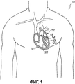
фиг.1 схематичное изображение пациента, сердце которого показано в сечении, а устройство по варианту осуществления настоящего изобретения схематично изображено как опора митрального клапана;figure 1 is a schematic illustration of a patient whose heart is shown in cross section, and the device according to a variant implementation of the present invention is schematically depicted as a support of the mitral valve;
фиг.1А - вид в сечении левого желудочка, где митральный клапан показан в перспективе;figa is a view in section of the left ventricle, where the mitral valve is shown in perspective;
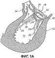
фиг.2 - вид в перспективе несущего тела устройства по первому варианту осуществления изобретения;figure 2 is a perspective view of the carrier body of the device according to the first embodiment of the invention;
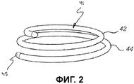
фиг.3 - вид в сечении несущего тела на фиг.2;figure 3 is a view in section of a supporting body in figure 2;
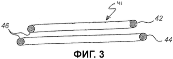
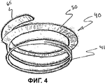
фиг.4 - вид в перспективе первого варианта осуществления устройства, содержащего несущее тело, показанное на фиг.2;FIG. 4 is a perspective view of a first embodiment of a device comprising a carrier body shown in FIG. 2;
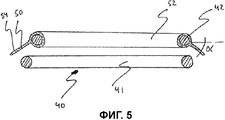
фиг.5 - вид в сечении устройства на фиг.4;5 is a view in cross section of the device of figure 4;
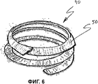
фиг.6 - вид в перспективе второго варианта осуществления изобретения устройства;6 is a perspective view of a second embodiment of the invention of the device;
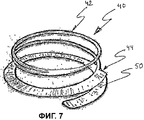
фиг.7 - вид в перспективе третьего варианта осуществления изобретения устройства;7 is a perspective view of a third embodiment of the invention of the device;
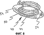
фиг.8 - вид в перспективе четвертого варианта осуществления изобретения устройства;Fig. 8 is a perspective view of a fourth embodiment of the invention;
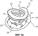
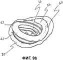
фиг.9a, 9b - виды в перспективе, которые изображают введение варианта осуществления устройства;figa, 9b are perspective views that depict the introduction of a variant implementation of the device;
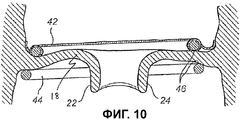
фиг.10 - вид в сечении, где показан вариант осуществления устройства, введенного в сердечный клапан;10 is a sectional view showing an embodiment of a device inserted into a heart valve;
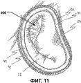
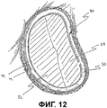
фиг.11 и 12 - схематичные изображения, на которых показан сердечный клапан до и после реконструкции с использованием устройства;11 and 12 are schematic views showing a heart valve before and after reconstruction using the device;
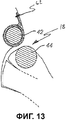
фиг.13 - вид в сечении, на котором показано устройство, закрепленное на фиброзном кольце;Fig. 13 is a sectional view showing a device mounted on a fibrous ring;
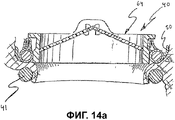
фиг.14a - вид в сечении, на котором показан первый вариант осуществления устройства, содержащего искусственный сердечный клапан;Fig. 14a is a sectional view showing a first embodiment of a device comprising an artificial heart valve;
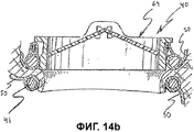
фиг.14b - вид в сечении, на котором показан второй вариант осуществления устройства, содержащего искусственный сердечный клапан;Fig. 14b is a sectional view showing a second embodiment of an apparatus comprising an artificial heart valve;
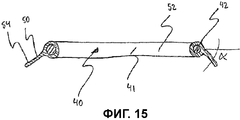
фиг.15 - вид в сечении альтернативного устройства, имеющего петлеобразную опору, несущую фланцевый узел.15 is a cross-sectional view of an alternative device having a loop-shaped support bearing a flange assembly.
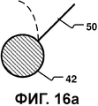
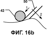
фиг.16a и 16b - виды в сечении вариантов осуществления с привлечением изменения формы; а такжеfiga and 16b are views in cross section of embodiments with the involvement of a change in shape; as well as
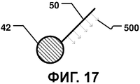
фиг.17 - вид в сечении, на котором схематично изображен фланцевый узел, обладающий элементами в виде зубцов для прикрепления к ткани.17 is a sectional view schematically showing a flange assembly having teeth elements for attachment to tissue.
ОПИСАНИЕ ВАРИАНТОВ ОСУЩЕСТВЛЕНИЯDESCRIPTION OF EMBODIMENTS
Конкретные варианты осуществления изобретения будут теперь описаны со ссылкой на сопровождающие чертежи. Данное изобретение, однако может быть осуществлено во множестве различных форм и его не следует толковать как ограниченное вариантами осуществления, изложенными в настоящем описании; скорее, эти варианты осуществления предоставлены для того, чтобы данное раскрытие было доскональным и полным и целиком передавало объем изобретения специалистам в данной области техники. Терминология, использованная в подробном описании вариантов осуществления, изображенных на сопровождающих чертежах, не направлена на ограничение изобретения. На чертежах одинаковые номера соответствуют одинаковым элементам.Specific embodiments of the invention will now be described with reference to the accompanying drawings. The present invention, however, can be implemented in many different forms and should not be construed as limited to the embodiments set forth herein; rather, these embodiments are provided so that this disclosure is thorough and complete and fully conveys the scope of the invention to those skilled in the art. The terminology used in the detailed description of the embodiments depicted in the accompanying drawings is not intended to limit the invention. In the drawings, like numbers correspond to like elements.
На фиг.1 изображен пациент 10, сердце 12 которого, показанное в сечении, включает в себя левый желудочек 14 и правый желудочек 16. Идеи настоящего изобретения пригодны для приложения, например, к митральному клапану 18, который осуществляет подачу крови в левый желудочек 14. Митральный клапан 18, как лучше видно на фиг.1А, включает в себя фиброзное кольцо 20 и пару створок 22, 24, которые избирательно допускают и предотвращают ток крови в левый желудочек 14. Следует понимать, что термин «ткань клапана» широко используется на всем протяжении данного раскрытия предмета изобретения по отношению к чертежам. Принципы изобретения в равной степени применимы в отношении любой ткани клапана, такой как ткань фиброзного кольца, ткань створки или иная приложенная ткань сосуда. Створки 22, 24 поддерживаются для коаптации сухожильными нитями или хордами 26, 28, продолжающимися вверх от соответствующих сосочковых мышц 30, 32. Кровь поступает в левый желудочек 14 через митральный клапан 18 и изгоняется при последующем сокращении сердца 12 через аортальный клапан 34. Следует понимать, что настоящее изобретение применимо также к трикуспидальным клапанам сердца.Figure 1 shows a
Несущее тело 41, которое содержится в устройстве 40 по первому варианту осуществления изобретения, показано на фиг.2 и 3. Несущее тело 41 содержит первую и вторую петлеобразную опору 42, 44.The supporting
Использованный здесь термин «петлеобразный» следует толковать как криволинейной формы, которая может быть замкнутой как, по меньшей мере, часть кольца, например, с круглой, эллиптической или D-образной формой или любой иной замкнутой формой, которая может соответствовать форме фиброзного кольца клапана. Термин «петлеобразный» также включает в себя криволинейную форму, которая является открытой и образует форму дуги, такую как С-образная форма или U-образная форма, которая включает в себя угол поворота, по меньшей мере, на 180° так, чтобы опора могла прилегать к ткани клапана вдоль большей части формы кольцевого клапана. Термин «петлеобразный» также включает в себя криволинейную форму, перекрывающую себя с образованием участка спирали.As used herein, the term “loop-like” should be interpreted as a curved shape that can be closed as at least part of a ring, for example, with a round, elliptical or D-shape or any other closed shape that can correspond to the shape of the fibrous ring of the valve. The term "loop" also includes a curved shape that is open and forms an arc shape, such as a C-shape or U-shape, which includes an angle of rotation of at least 180 ° so that the support can adhere to the valve tissue along most of the shape of the annular valve. The term “loop” also includes a curved shape that overlaps itself to form a portion of the spiral.
Термин «петлеобразный» также включает в себя трехмерные кривые, как упоминалось в предыдущем параграфе.The term “loop-like” also includes three-dimensional curves, as mentioned in the previous paragraph.
Форма петли, по меньшей мере части, по меньшей мере одной из опор 42, 44 в некоторых вариантах осуществления может быть также отконфигурирована для пациента. Форма может быть сконструирована специально с учетом анатомии пациента. Форма петли специально для пациента может быть в действительности получена из 3D-данных пациента, полученных, например, с использованием средства для визуализации, такого как магнитно-резонансное исследование или компьютерная томография.The shape of the loop of at least a portion of at least one of the
В патентах США 6,419,696, 6,730,121, 6,964,684, а также публикации WO 2006/091163, закрепленных за тем же заявителем, что и настоящая заявка, и включенных сюда путем ссылки во всей их полноте для любых целей, раскрыты устройства для восстановления и замены сердечного клапана в различных вариантах осуществления. Устройства включают в себя, по меньшей мере, первое и второе опорные кольца, соединенные друг с другом в петлеобразных конфигурациях для примыкания к противоположным сторонам фиброзного кольца клапана. Клапан, используемый для замены, может быть прикреплен к петлеобразным устройствам.In US patents 6,419,696, 6,730,121, 6,964,684, as well as publications WO 2006/091163, assigned to the same applicant as this application, and incorporated herein by reference in their entirety for any purpose, disclosed are devices for repairing and replacing a heart valve in various embodiments. The devices include at least a first and a second support ring connected to each other in loop-like configurations to abut against opposite sides of the fibrous ring of the valve. The valve used for replacement can be attached to loop-shaped devices.
Первая опора 42 может быть непрерывной со второй опорой 44 или составлять с ней единое целое таким образом, чтобы опоры 42, 44 приняли спиральную конфигурацию в форме спирали или брелока для ключей с двумя петлями.The
Вторая опора 44 может иметь внешнюю границу или протяженность, величина которой больше, чем у внешней границы первой опоры 42. В варианте осуществления опоры 42, 44 могут иметь подобные друг другу формы, при этом вторая опора 44 - больше по размеру, чем первая опора 42. Это имеет преимущество в создании зажима ткани клапана между первой опорой 42 и второй опорой 44.The
Конец 45 второй опоры 44, который является ведущим для спирали в процессе введения устройства в клапан, может в варианте осуществления иметь больший угол наклона, чем остальная спираль. Это предполагает, что ведущий конец 45 спирали в процессе вращательного движения при установке по месту в клапане не будет непосредственно контактировать с тканью клапана, и поэтому риск того, что спираль зацепит хорды, снижается.The end 45 of the
Несущее тело 41 показано в сечении на фиг.3. Несущее тело 41 в варианте осуществления имеет, по меньшей мере, частично круглую форму в сечении. В других вариантах осуществления сечение несущего тела 41 может быть по существу плоским, овальным, сплющенным и/или иметь сплющенные края.The
В вариантах осуществления противоположные поверхности 46, таким образом, обеспечивают зажим для захвата между ними ткани клапана. Круглое сечение также имеет преимущество в создании зажима для ткани клапана, который не повредит створки при их движении в процессе нормальной работы сердца.In embodiments, opposing
Вторая петлеобразная опора 44 незначительно смещена в радиальном направлении по отношению к первой петлеобразной опоре 42. Это предполагает, что первая и вторая петлеобразные опоры 42, 44 не располагаются непосредственно друг над другом в некоторых вариантах осуществления. Зажим между первой опорой 42 и второй опорой 44, таким образом, не строго определен в радиальном направлении клапана. Это предполагает, что усилие защемления между опорами не сконцентрировано в каком-то определенном радиальном положении клапана. Таким образом, усилие защемления не оказывает влияние на движение створок в процессе нормальной работы сердца, а риск разрушения створок в зажиме снижается.The second loop-shaped
Опоры в некоторых вариантах осуществления могут быть взаимосвязаны таким образом, чтобы внешний контур первой опоры 42 имел диаметр, соответствующий центровой линии второй опоры 44. Таким образом, опоры 42, 44 могут в некоторой степени перекрываться так, чтобы не позволить ткани перемещаться в зажиме, и форма клапана предпочтительно поддерживается.The supports in some embodiments may be interconnected so that the outer contour of the
Кроме того, сечение опор 42, 44, по существу круглое, что обеспечивает мягкий контакт между опорами и тканью клапана, что дополнительно снижает риск разрушения в створках.In addition, the cross section of the
Несущее тело 41 может быть выполнено из стержня, изготовленного из жесткого материала, такого как металл, например, титан или пластик. Могут быть использованы любые пригодные материалы, используемые в медицине.The supporting
Жесткий материал может обеспечивать функцию пружины в пассивном исполнении так, чтобы с приложением усилия кольца спирали могли незначительно отдалиться друг от друга, а при снятии этого усилия - изогнуться назад навстречу друг другу. Стержень несущего тела 41 может иметь покрытие из более мягкого слоя, такого как ткань.Rigid material can provide a spring function in a passive design so that with the application of force, the spiral rings can slightly move away from each other, and when this effort is removed, it can be bent back towards each other. The core of the
По альтернативному варианту несущее тело 41 может быть выполнено из материала с эффектом запоминания формы. Тогда несущее тело 41 примет желаемую запрограммированную форму при, например, нагреве до определенной температуры. Это позволяет сжать или распрямить несущее тело 41 для придания формы, которая более подходит для подачи в процессе введения, и принять форму спирали после введения в сердечный клапан. Кроме того, фланцевый узел может быть выполнен из такого материала с эффектом запоминания формы, например, для обеспечения его первой формы, формы при подаче, и второй формы, формы после подачи.Alternatively, the
Обратимся к фиг.4 и 5, на которых раскрыт первый вариант осуществления медицинского устройства 40. Устройство 40 содержит несущее тело 41 в соответствии с тем, что описано выше со ссылкой на фиг.2 и 3, на основании чего несущее тело 41 как таковое далее не обсуждается.Referring to FIGS. 4 and 5, a first embodiment of a
Устройство 40 содержит фланцевый узел 50, соединенный с несущим телом 41, а точнее с первой петлеобразной опорой 42. Фланцевый узел 50 имеет в варианте осуществления непрерывную протяженность вдоль периферии первой петлеобразной опоры 42.The
В некоторых вариантах осуществления фланцевый узел 50 может составлять единое целое, по меньшей мере, с участком несущего тела 41, например, как показано на фиг.16a.In some embodiments, the
В некоторых вариантах осуществления фланцевый узел 50 выполнен из гибкого материала 52 в форме трубки, перенесенного на первую петлеобразную опору 42, посредством чего достигается неплотное, по существу соосное соединение между петлеобразной опорой и фланцевым узлом. Соединение может быть также неподвижным или жестким. Гибкий материал может представлять собой, например, ткань или тканую структуру, выполненную из полиэтилена (РЕ) или политетрафторэтилена (PTFE). Ткань имеет преимущество в том, что являет собой грубую, с отверстиями или пористую поверхность, которая способствует росту и избыточному росту эндотелия. Кроме того, в ткань легко входят нити или скобы. В дополнение к этому гибкий материал позволяет согласовать фланцевый узел 50 с фиброзным кольцом.In some embodiments, the
Фланцевый узел 50 в раскрытом варианте осуществления образует фланцевую поверхность 54, продолжающуюся вниз от несущего тела. Точнее, фланцевый узел 50 образует в некоторых вариантах осуществления угол a с горизонтальной диаметральной плоскостью, образованной первой петлеобразной опорой. Угол a составляет примерно 30-60°, как, например, 40-50°, с диаметральной плоскостью. Такой угол улучшает визуальную доступность в процессе введения устройства. В некоторых вариантах осуществления улучшенная визуальная доступность может быть обеспечена в процессе введения устройства, после чего фланцевый узел 50 изменяет форму, приобретая такое положение, которое способствует его прикреплению к окружающей ткани. Таким образом, медицинские вмешательства для восстановления и/или замены сердечного клапана могут проводиться в существенно ускоренном темпе.The
В практическом варианте осуществления фланцевая поверхность 54 имеет ширину в пределах примерно 2-4 мм, как, например, 2,5-3,5 мм. Ширина фланца, радиально выступающего наружу, позволяет обозначить для хирурга область, в которую следует поместить нити или скобы при креплении устройства к фиброзному кольцу. Это дополнительно обсуждается ниже со ссылкой на фиг.13.In a practical embodiment, the
Первоначально, до введения в сердечный клапан, фланцевая поверхность 54 продолжается вниз. После расположения на предсердной стороне сердечного клапана, устройство размещается, примыкая к фиброзному кольцу, посредством чего фланцевый узел согласуется с фиброзным кольцом, изменяя свой угол от продолжения вниз на продолжение вверх. Эта способность к согласованию - сочетание гибкости материала (из ткани) и ширины средства с фланцем.Initially, prior to insertion into the heart valve,
На своей внешней периферии фланцевый узел 50 может содержать армирующий элемент 65, который схематично изображен на фиг.4. Такой армирующий элемент может, например, иметь форму нити или кромки (bead).At its outer periphery, the
Обратимся к фиг.6, на которой раскрыт второй вариант осуществления устройства 40. Это устройство отличается от того, что раскрыто на фиг.4 и 5, в том, что фланцевый узел 50 продолжается от первой петлеобразной опоры 42 на вторую петлеобразную опору 44. Фланцевый узел 50 может быть выполнен как цельный или из отделенных друг от друга первой и второй частей, причем первая часть соединена с первой кольцеобразной опорой, а вторая часть соединена со второй петлеобразной опорой. Соединение может быть жестким соединением или неплотным соединением. Последнее может достигаться, если фланцевый узел перенесен на петлеобразную опору (петлеобразные опоры).Referring to FIG. 6, a second embodiment of the
Фланцевый узел может быть непрерывным или прерывающимся вдоль своей протяженности.The flange assembly may be continuous or discontinuous along its length.
Второй вариант осуществления пригоден при использовании устройства как для восстановления, так и для замены клапана.The second embodiment is suitable when using the device for both restoration and valve replacement.
Обратимся к фиг.7, на которой раскрыт третий вариант осуществления устройства 40. Устройство 40 отличается от того, что раскрыто на фиг.4 и 5, в том, что фланцевый узел 50 продолжается вдоль второй петлеобразной опоры 44. Будучи расположенной в сердечном клапане, вторая петлеобразная опора выполнена с возможностью примыкания к желудочковой стороне сердечного клапана, в то время как первая петлеобразная опора 42 выполнена с возможностью примыкания к предсердной стороне. Фланцевый узел 50 может быть непрерывным или прерывающимся вдоль своей протяженности. Третий вариант осуществления может быть пригоден при использовании для замены клапана. Опорой искусственному, т.е. протезному клапану может служить либо несущее тело, либо средство с фланцем.Referring to FIG. 7, a third embodiment of a
Обратимся к фиг.8, на которой раскрыт четвертый вариант осуществления устройства 40. Устройство 40 отличается от того, что раскрыто на фиг.4 и 5, в том, что фланцевый узел 50 продолжается вдоль второй петлеобразной опоры 44 и образует две фланцевые поверхности 54, причем обе соединены со второй петлеобразной опорой 44. Фланцевые поверхности 54 размещены на второй петлеобразной опоре 44 таким образом, чтобы перекрывать комиссуры, когда устройство размещено в сердечном клапане, примыкая к фиброзному кольцу. Посредством этого две фланцевые поверхности образуют уплотнение, предотвращающее возможную протечку крови со стороны желудочка на сторону предсердия.Referring to FIG. 8, the fourth embodiment of the
В вариантах осуществления устройства, обсуждавшихся выше, фланцевый узел был раскрыт либо как непрерывный, либо как прерывающийся вдоль своей протяженности. Фланцевый узел может дополнительно быть неравномерным по ширине, которая изменяется вдоль протяженности узла. Например, ширина может быть большей в области, соответствующей положению перекрытия комиссуры, когда устройство размещено в сердечном клапане, примыкая к фиброзному кольцу.In the embodiments of the device discussed above, the flange assembly was disclosed either as continuous or as interrupted along its length. The flange assembly may further be uneven in width, which varies along the extent of the assembly. For example, the width may be greater in the area corresponding to the position of overlapping commissure when the device is placed in the heart valve adjacent to the fibrous ring.
Со ссылкой на фиг.9-11 теперь будет описан способ для восстановления сердечного клапана посредством устройства по первому варианту осуществления.With reference to Figs. 9-11, a method for reconstructing a heart valve by the device of the first embodiment will now be described.
Прежде всего, доступ к сердечному клапану достигается по традиционной технологии, включающей в себя остановку сердца и вскрытие грудной клетки. По альтернативному варианту, может быть применена техника доставки на основе внутрипросветного катетера. На фиг. 9а показано устройство 40 в процессе введения к митральному клапану 18 со стороны предсердия. Устройство 40 переносится на носителе или инструменте (не показан), который соединен с рукояткой (stem) для дистанционного управления позиционированием носителя. Как показано на фиг.9b, конец 56 второй петлеобразной опоры 44 подведен к отверстию митрального клапана 18 у комиссуры 60 между створками 22, 24. Конец 56 вводится через отверстие, и носитель поворачивается на 360 градусов. Таким образом, вторая опора 44 будет вкручена на свое место на одной стороне клапана 18, в то время как первая опора 42 с фланцевым узлом располагается на противоположной стороне клапана 18. В процессе этого вращательного движения фланцевый узел 50 отклоняется от своего первоначального направления, которое образует угол 30-60° вниз от диаметральной плоскости, образованной опорой 42, меняя его на направление под углом вверх от диаметральной плоскости, соответствуя стенке, образованной фиброзным кольцом 20. Изменение направления, допускаемое гибкостью фланцевого узла 50, приводит к плотному прилеганию между фланцевым узлом 50 и предсердной стороной фиброзного кольца 20. При необходимости фланцевый узел 50 может быть дополнительно согласован с фиброзным кольцом 20. Таким образом, устройство 40 располагается с зацеплением с клапаном 18, как показано на фиг.10.First of all, access to the heart valve is achieved by traditional technology, including cardiac arrest and opening of the chest. Alternatively, a delivery technique based on an intraluminal catheter may be used. In FIG. 9a shows the
Кроме того, опоры 42, 44 расположены на противоположных сторонах клапана 18, зажимая ткань клапана между собой для поддержки формы клапана 18. Теперь створки 22, 24 могут быть подтянуты друг к другу через зажим, образованный опорными кольцами 42, 44, для того, чтобы реконструировать форму клапана 18. Створки можно подтянуть через зажим посредством инструмента в виде щипцов. Опоры 42, 44 можно отогнуть друг от друга для того, чтобы позволить подтянуть створки 22, 24 через зажим навстречу друг другу для предотвращения проскальзывания створок 22, 24 назад. Фиброзное кольцо 20 клапана может таким образом быть реконструировано, а новая форма сохранена с помощью опор 42, 44, см. Фиг.11 и 12 с картиной до и после реконструкции. На фиг.11 показана дефектная область 400 смыкания створок 22, 24 клапана. Опоры 42, 44 могут иметь шероховатые, противоположно направленные поверхности 46, чтобы лучше удерживать створки 22, 24 от проскальзывания через зажим и для сохранения фиброзного кольца 20 клапана в его измененной форме.In addition, the
Устройство 40 теперь можно скрепить с клапаном 18 для усиления закрепления относительного положения между опорами 42, 44 и тканью клапана, см. фиг.13. Закрепление можно осуществить скобами или нитями 62, которые располагают сквозь фланцевый узел 50 и его периферийную фланцевую поверхность 54. Если последняя поверхность выполнена из ткани, то она легко проницаема. Скобы и нити 62 предпочтительно ориентируются и располагаются в направлении вдоль окружности фланцевого узла 50. Количество точек крепления выбирается произвольно для обеспечения прочного закрепления.The
В некоторых вариантах осуществления фланцевый узел 50 обеспечивает лучшее посадочное место и предотвращает сдвиг устройства 40. Таким образом, устройство 40 располагается более устойчиво при операции, что предпочтительно, особенно для долгосрочной работы устройства после введения.In some embodiments, the
Как изображено на фиг.10, вторая опора 44 незначительно смещена в радиальном направлении по отношению к первой опоре 42. Это предполагает, что первая и вторая опоры 42, 44 не располагаются непосредственно друг над другом. Зажим между первой опорой 42 и второй опорой 44, таким образом, не строго определен в радиальном направлении клапана. Это подразумевает, что усилие защемления между опорами не сконцентрировано в каком-то определенном радиальном положении клапана. Таким образом, усилие защемления не оказывает влияние на движение створок в процессе нормальной работы сердца, а риск разрушения створок в зажиме снижается. Опоры взаимосвязаны таким образом, чтобы внешний контур первой опоры 42 имел диаметр, соответствующий центровой линии второй опоры 44. Таким образом, опоры 42, 44 в некоторой степени перекрываются так, чтобы не позволить ткани перемещаться в зажиме, и форма клапана сохраняется. Кроме того, сечение опор 42, 44 - круглое, что также обеспечивает мягкий контакт между опорами и тканью клапана, что дополнительно снижает риск разрушения в створках.As shown in FIG. 10, the
Описанный выше способ может применяться независимо от формы, положения или протяженности средства с фланцем. Кроме того, этот способ может применяться независимо от того, вводят ли устройство со стороны предсердия или со стороны желудочка.The method described above can be applied regardless of the shape, position or extent of the tool with a flange. In addition, this method can be applied regardless of whether the device is inserted from the atrium or from the ventricle.
Устройство, в котором фланцевый узел имеется на первой, верхней, петлеобразной опоре, пригодно в том случае, когда устройство должно быть расположено на стороне предсердия, обеспечивая поверхность для закрепления на предсердной стороне фиброзного кольца. Такое устройство также пригодно для того, чтобы нести на себе искусственный клапан. Кроме того, устройство, в котором фланцевый узел имеется на второй петлеобразной опоре, пригодно в том случае, когда вторая петлеобразная опора должна быть расположена на желудочковой стороне сердечного клапана.A device in which a flange assembly is provided on a first, upper, loop-like support is suitable when the device is to be located on the atrial side, providing a surface for fixing on the atrial side of the fibrous ring. Such a device is also suitable for carrying an artificial valve. In addition, a device in which a flange assembly is provided on the second loop-shaped support is suitable when the second loop-shaped support should be located on the ventricular side of the heart valve.
Устройство, в котором фланцевый узел продолжается от первой ко второй петлеобразной опоре, пригодно независимо от того, располагается ли устройство на предсердной стороне или желудочковой стороне сердечного клапана.A device in which the flange assembly extends from the first to the second loop-shaped support is suitable regardless of whether the device is located on the atrial side or the ventricular side of the heart valve.
Со ссылкой на фиг.14а и фиг.14b, следует понимать, что устройство также можно использовать для замены клапанов сердца. Для этой цели устройство 40 содержит в дополнение к несущему телу 41 и фланцевому узлу 50 искусственный клапан 64. Фланцевый узел 50 может нести на себе первая петлеобразная опора 42, как показано на фиг.14а. По альтернативному варианту, как показано на фиг.14b, фланцевый узел 50 может продолжаться от первой 42 ко второй 44 опоре. Хотя и не показано, следует понимать, что каждая опора 42, 44 может нести на себе свой собственный фланцевый узел, или же фланцевый узел может нести на себе только вторая опора 44.With reference to figa and fig.14b, it should be understood that the device can also be used to replace heart valves. For this purpose, the
Способ введения, позиционирования и закрепления устройства, в общем, тот же, что использованный при восстановлении сердечного клапана, в силу чего способ как таковой далее не обсуждается.The method of introducing, positioning and securing the device is generally the same as that used to repair the heart valve, whereby the method as such is not further discussed.
Следует подчеркнуть, что описанные здесь предпочтительные варианты осуществления никоим образом не являются ограничивающими, и возможны многие альтернативные варианты осуществления в объеме охраны, определяемом прилагаемой формулой изобретения.It should be emphasized that the preferred embodiments described herein are in no way limiting, and many alternative embodiments are possible within the scope of protection defined by the appended claims.
Например, устройство 40 и его несущее тело 41 были раскрыты как имеющие первую 42 и вторую 44 петлеобразную опору. Устройство 40 может применяться лишь с одной петлеобразной опорой, которая несет на себе фланцевый узел 50. Один такой вариант осуществления раскрыт на фиг.15.For example, the
Кроме того, доступ к сердечному клапану может быть эндоскопическим или чреспросветным, основанным на использовании катетера. В этом случае устройство 40 требуется ввести через тонкую трубку (эндоскоп или катетер). Это предполагает, что устройство 40 потребуется сжать в процессе введения, чтобы провести через эндоскоп или катетер. Устройство 40 должно принять свою соответствующую форму после того, как оно прошло через эндоскоп. Поэтому, при использовании подхода на основе применения эндоскопа или катетера, несущее тело может быть предпочтительно выполнено из материала с эффектом запоминания формы. Это позволяет сжать устройство 40, а также получить устойчивую форму после приложения к сердечному клапану. По альтернативному варианту, доступ к сердечному клапану можно получить через катетер, который проходит через сосудистую систему к сердцу. В этом случае, опоры могут быть выполнены из материала с эффектом запоминания формы, при этом в процессе введения они продолжаются вдоль катетера в гибком состоянии, а после выталкивания из катетера у сердечного клапана принимают предварительно-напряженную форму спирали для того, чтобы примкнуть к сердечному клапану с противоположных сторон.In addition, access to the heart valve may be endoscopic or translucent based on the use of a catheter. In this case, the
Первая и вторая петлеобразные опоры могут соединяться друг с другом посредством соединительной части так, чтобы образовывать форму спирали. Форма спирали, которую имеет устройство, является предпочтительной в процессе введения, поскольку устройство можно затем вкрутить на место, как описано выше. Однако соединительная часть может отсоединяться, по меньшей мере, от одной из опор. Таким образом, после введения устройства соединительная часть может быть отсоединена и удалена из отверстия клапана.The first and second loop-shaped supports can be connected to each other by means of a connecting part so as to form a spiral shape. The spiral shape that the device has is preferred during insertion, since the device can then be screwed into place as described above. However, the connecting part may be detached from at least one of the supports. Thus, after the introduction of the device, the connecting part can be disconnected and removed from the valve opening.
Петлеобразная опора (петлеобразные опоры) и фланцевый узел могут обеспечиваться как раздельные части.A loop-shaped support (loop-shaped supports) and a flange assembly can be provided as separate parts.
Кроме того, следует понимать, что средство с фланцем или, по меньшей мере, его крыловидная часть может образовывать произвольный угол с соответствующей ему петлеобразной опорой.In addition, it should be understood that the tool with a flange or at least its pterygoid part can form an arbitrary angle with its corresponding loop-shaped support.
На фиг.16a и 16b - виды в сечении вариантов осуществления с привлечением изменения формы.On figa and 16b are views in cross section of embodiments with the involvement of a change in shape.
На фиг.16a изображено изменение формы фланцевого узла 50, например, когда он не находится на линии прямой видимости хирурга в процессе введения (пунктирная линия) и когда, будучи в контакте с тканью тела, переходит ко второй форме (сплошная линия) для присоединения к ткани.On figa shows a change in the shape of the
На фиг.16b изображено изменение формы фланцевого узла 50 в два этапа или в двух направлениях. Во-первых, фланцевый узел может сократиться в первом направлении, чтобы исключить наличие там морщин или складок. После этого или параллельно с этим, фланцевый узел 50 может изменить форму во втором направлении, например, как описано со ссылкой на фиг.16a.On fig.16b shows a change in the shape of the
На фиг.17 - вид в сечении, на котором схематично изображен фланцевый узел 50, обладающий элементами 500 в виде зубцов для прикрепления устройства 40 к ткани. Фланцевый узел 50 может, таким образом, нести на себе закрепляющие элементы. Фланцевый узел 50 может, таким образом, вводиться в тело более эффективно.17 is a sectional view schematically showing a
В некоторых вариантах осуществления для частей устройства 40 могут быть использованы различные материалы. Например, внутренние кольца 42, 44 могут быть выполнены из материала, придающего более высокую жесткость, чем та, что у более гибкой наружной части, например, фланцевого узла 50.In some embodiments, various materials may be used for parts of the
В то время как здесь было описано и изображено несколько вариантов осуществления настоящего изобретения, те, кто обладают средними познаниями в данной области техники, легко представят себе множество других средств и/или структур для выполнения функций и/или получения результатов, и/или одно или несколько описанных здесь преимуществ, и каждое из таких изменений и модификаций считается входящим в объем настоящего изобретения. В более общем смысле, специалистам в данной области техники ясно, что все параметры, размеры, материалы и конфигурации, описанные здесь, служат примером, а действительные параметры, размеры, материалы и/или конфигурации будут зависеть от конкретного применения или конкретных применений, для которых используются идеи настоящего изобретения.While several embodiments of the present invention have been described and depicted herein, those with average knowledge of the art will easily imagine many other means and / or structures for performing functions and / or obtaining results, and / or one or several of the advantages described herein, and each of these changes and modifications is considered to be included in the scope of the present invention. In a more general sense, it will be apparent to those skilled in the art that all parameters, dimensions, materials and configurations described herein are exemplary, and actual parameters, dimensions, materials and / or configurations will depend on the particular application or specific applications for which the ideas of the present invention are used.
Специалисты в данной области техники обнаружат или будут в состоянии выявить, с использованием лишь шаблонных экспериментов, многие эквиваленты конкретным вариантам осуществления изобретения, описанным здесь. Таким образом, следует понимать, что вышеизложенные варианты осуществления приведены лишь как примеры и что в объеме прилагаемой формулы изобретения и эквивалентов к ней изобретение может быть практически осуществлено иначе, чем конкретно описано и заявлено в формуле изобретения. Настоящее изобретение направлено на каждые отдельные признак, систему, изделие, материал, набор и/или способ, описанные здесь. Кроме того, любое сочетание двух или более таких признаков, систем, изделий, материалов, наборов и/или способов, если такие признаки, системы, изделия, материалы, наборы и/или способы не являются взаимно несовместимыми, включено в объем настоящего изобретения как ограниченное прилагаемой формулой изобретения.Those skilled in the art will detect or will be able to identify, using only template experiments, many equivalents to the specific embodiments of the invention described herein. Thus, it should be understood that the foregoing embodiments are merely exemplary and that, within the scope of the appended claims and their equivalents, the invention may be practiced otherwise than specifically described and claimed in the claims. The present invention is directed to each individual feature, system, product, material, kit and / or method described herein. In addition, any combination of two or more of such features, systems, products, materials, kits and / or methods, if such features, systems, products, materials, kits and / or methods are not mutually incompatible, is included in the scope of the present invention as limited the attached claims.
Claims (21)
первую петлеобразную опору, выполненную с возможностью примыкания к первой стороне сердечного клапана, и
первый фланцевый узел, который соединен с упомянутой первой петлеобразной опорой и проходит по периферии первой петлеобразной опоры,
при этом первый фланцевый узел содержит первый армирующий элемент.1. A medical device for improving the functioning of the heart valve, consisting of valve tissue including a fibrous ring and a plurality of valves, the medical device comprising:
a first loop-shaped support configured to abut against a first side of the heart valve, and
a first flange assembly that is connected to said first loop-shaped support and extends around the periphery of the first loop-shaped support,
wherein the first flange assembly comprises a first reinforcing element.
Applications Claiming Priority (4)
| Application Number | Priority Date | Filing Date | Title |
|---|---|---|---|
| SE0602421A SE530568C2 (en) | 2006-11-13 | 2006-11-13 | Medical device for improving function of heart valve, has flange unit connected to loop-shaped support and provided to be arranged against annulus when loop shaped support abut heart valve |
| SE0602421-0 | 2006-11-13 | ||
| US87612306P | 2006-12-21 | 2006-12-21 | |
| US60/876,123 | 2006-12-21 |
Related Parent Applications (1)
| Application Number | Title | Priority Date | Filing Date |
|---|---|---|---|
| RU2009122483/14A Division RU2465869C2 (en) | 2006-11-13 | 2007-11-12 | Device and method for improvement of heart valve functioning |
Publications (2)
| Publication Number | Publication Date |
|---|---|
| RU2012132975A RU2012132975A (en) | 2014-02-10 |
| RU2536701C2 true RU2536701C2 (en) | 2014-12-27 |
Family
ID=39472688
Family Applications (2)
| Application Number | Title | Priority Date | Filing Date |
|---|---|---|---|
| RU2012132975/14A RU2536701C2 (en) | 2006-11-13 | 2007-11-12 | Device and method for improving cardiac valve operation |
| RU2009122483/14A RU2465869C2 (en) | 2006-11-13 | 2007-11-12 | Device and method for improvement of heart valve functioning |
Family Applications After (1)
| Application Number | Title | Priority Date | Filing Date |
|---|---|---|---|
| RU2009122483/14A RU2465869C2 (en) | 2006-11-13 | 2007-11-12 | Device and method for improvement of heart valve functioning |
Country Status (16)
| Country | Link |
|---|---|
| US (6) | US8663322B2 (en) |
| EP (3) | EP2081518B1 (en) |
| JP (4) | JP5047302B2 (en) |
| KR (1) | KR101448326B1 (en) |
| CN (2) | CN102389341B (en) |
| AT (1) | ATE456335T1 (en) |
| AU (1) | AU2007321262B2 (en) |
| BR (1) | BRPI0716677B8 (en) |
| CA (1) | CA2668548C (en) |
| DE (1) | DE602007004643D1 (en) |
| ES (3) | ES2338386T3 (en) |
| PL (3) | PL2081518T3 (en) |
| RU (2) | RU2536701C2 (en) |
| SE (1) | SE530568C2 (en) |
| WO (1) | WO2008058940A1 (en) |
| ZA (1) | ZA201005259B (en) |
Cited By (1)
| Publication number | Priority date | Publication date | Assignee | Title |
|---|---|---|---|---|
| RU174260U1 (en) * | 2017-06-01 | 2017-10-09 | Сергей Владимирович Осутин | A host instrument for creating artificial mitral heart chords |
Families Citing this family (184)
| Publication number | Priority date | Publication date | Assignee | Title |
|---|---|---|---|---|
| US6736845B2 (en) * | 1999-01-26 | 2004-05-18 | Edwards Lifesciences Corporation | Holder for flexible heart valve |
| ITMI20011012A1 (en) | 2001-05-17 | 2002-11-17 | Ottavio Alfieri | ANNULAR PROSTHESIS FOR MITRAL VALVE |
| US7935145B2 (en) | 2001-05-17 | 2011-05-03 | Edwards Lifesciences Corporation | Annuloplasty ring for ischemic mitral valve insuffuciency |
| US6908482B2 (en) | 2001-08-28 | 2005-06-21 | Edwards Lifesciences Corporation | Three-dimensional annuloplasty ring and template |
| US7942927B2 (en) * | 2004-03-15 | 2011-05-17 | Baker Medical Research Institute | Treating valve failure |
| CN102113922B (en) | 2005-09-07 | 2013-03-27 | 梅德坦提亚国际有限公司 | A device for improving the function of a heart valve |
| WO2007100408A2 (en) | 2005-12-15 | 2007-09-07 | Georgia Tech Research Corporation | Papillary muscle position control devices, systems & methods |
| CA2669195C (en) | 2005-12-15 | 2013-06-25 | Georgia Tech Research Corporation | Systems and methods to control the dimension of a heart valve |
| WO2007100410A2 (en) | 2005-12-15 | 2007-09-07 | Georgia Tech Research Corporation | Systems and methods for enabling heart valve replacement |
| DE602007012691D1 (en) | 2006-05-15 | 2011-04-07 | Edwards Lifesciences Ag | SYSTEM FOR CHANGING THE GEOMETRY OF THE HEART |
| US7879087B2 (en) * | 2006-10-06 | 2011-02-01 | Edwards Lifesciences Corporation | Mitral and tricuspid annuloplasty rings |
| US9232997B2 (en) | 2006-11-07 | 2016-01-12 | Corvia Medical, Inc. | Devices and methods for retrievable intra-atrial implants |
| US10624621B2 (en) | 2006-11-07 | 2020-04-21 | Corvia Medical, Inc. | Devices and methods for the treatment of heart failure |
| US8460372B2 (en) | 2006-11-07 | 2013-06-11 | Dc Devices, Inc. | Prosthesis for reducing intra-cardiac pressure having an embolic filter |
| US10413284B2 (en) | 2006-11-07 | 2019-09-17 | Corvia Medical, Inc. | Atrial pressure regulation with control, sensing, monitoring and therapy delivery |
| US20110257723A1 (en) | 2006-11-07 | 2011-10-20 | Dc Devices, Inc. | Devices and methods for coronary sinus pressure relief |
| CN101605511B (en) | 2007-02-09 | 2013-03-13 | 爱德华兹生命科学公司 | Progressively sized annuloplasty rings |
| US8529620B2 (en) * | 2007-05-01 | 2013-09-10 | Ottavio Alfieri | Inwardly-bowed tricuspid annuloplasty ring |
| US8377117B2 (en) | 2007-09-07 | 2013-02-19 | Edwards Lifesciences Corporation | Active holder for annuloplasty ring delivery |
| DE202008018589U1 (en) | 2007-09-26 | 2016-03-14 | St. Jude Medical, Inc. | Foldable heart valve prostheses |
| US9532868B2 (en) | 2007-09-28 | 2017-01-03 | St. Jude Medical, Inc. | Collapsible-expandable prosthetic heart valves with structures for clamping native tissue |
| US8784483B2 (en) * | 2007-11-19 | 2014-07-22 | The Cleveland Clinic Foundation | Apparatus and method for treating a regurgitant heart valve |
| EP2072027B1 (en) | 2007-12-21 | 2020-06-17 | Medtentia International Ltd Oy | pre-annuloplasty device and method |
| WO2009137776A1 (en) * | 2008-05-09 | 2009-11-12 | Edwards Lifesciences Corporation | Degenerative valvular disease specific annuloplasty rings |
| US8323335B2 (en) | 2008-06-20 | 2012-12-04 | Edwards Lifesciences Corporation | Retaining mechanisms for prosthetic valves and methods for using |
| WO2010008548A2 (en) | 2008-07-15 | 2010-01-21 | St. Jude Medical, Inc. | Collapsible and re-expandable prosthetic heart valve cuff designs and complementary technological applications |
| WO2010098857A1 (en) | 2009-02-27 | 2010-09-02 | St. Jude Medical, Inc. | Stent features for collapsible prosthetic heart valves |
| WO2010129089A2 (en) * | 2009-04-28 | 2010-11-11 | Dc Devices, Inc. | Devices, systems and methods to treat heart failure |
| US9757107B2 (en) | 2009-09-04 | 2017-09-12 | Corvia Medical, Inc. | Methods and devices for intra-atrial shunts having adjustable sizes |
| US8870950B2 (en) | 2009-12-08 | 2014-10-28 | Mitral Tech Ltd. | Rotation-based anchoring of an implant |
| EP2528646A4 (en) | 2010-01-29 | 2017-06-28 | DC Devices, Inc. | Devices and systems for treating heart failure |
| CA2785041A1 (en) | 2010-01-29 | 2011-08-04 | Dc Devices, Inc. | Devices and methods for reducing venous pressure |
| WO2011109813A2 (en) | 2010-03-05 | 2011-09-09 | Edwards Lifesciences Corporation | Retaining mechanisms for prosthetic valves |
| WO2011111047A2 (en) | 2010-03-10 | 2011-09-15 | Mitraltech Ltd. | Prosthetic mitral valve with tissue anchors |
| US8579964B2 (en) | 2010-05-05 | 2013-11-12 | Neovasc Inc. | Transcatheter mitral valve prosthesis |
| JP5848345B2 (en) * | 2010-07-09 | 2016-01-27 | ハイライフ エスエーエス | Transcatheter atrioventricular valve prosthesis |
| US8657872B2 (en) | 2010-07-19 | 2014-02-25 | Jacques Seguin | Cardiac valve repair system and methods of use |
| US9763657B2 (en) | 2010-07-21 | 2017-09-19 | Mitraltech Ltd. | Techniques for percutaneous mitral valve replacement and sealing |
| US11653910B2 (en) | 2010-07-21 | 2023-05-23 | Cardiovalve Ltd. | Helical anchor implantation |
| WO2012012761A2 (en) | 2010-07-23 | 2012-01-26 | Edwards Lifesciences Corporation | Retaining mechanisms for prosthetic valves |
| CN103179920B (en) | 2010-08-24 | 2015-11-25 | 爱德华兹生命科学公司 | There is the flexible valve forming ring selecting control point |
| US10105224B2 (en) | 2010-09-01 | 2018-10-23 | Mvalve Technologies Ltd. | Cardiac valve support structure |
| EP2611391B1 (en) | 2010-09-01 | 2017-11-22 | Mvalve Technologies Ltd. | Cardiac valve support structure |
| US8932350B2 (en) | 2010-11-30 | 2015-01-13 | Edwards Lifesciences Corporation | Reduced dehiscence annuloplasty ring |
| US8888843B2 (en) | 2011-01-28 | 2014-11-18 | Middle Peak Medical, Inc. | Device, system, and method for transcatheter treatment of valve regurgitation |
| US8845717B2 (en) | 2011-01-28 | 2014-09-30 | Middle Park Medical, Inc. | Coaptation enhancement implant, system, and method |
| EP2673038B1 (en) | 2011-02-10 | 2017-07-19 | Corvia Medical, Inc. | Apparatus to create and maintain an intra-atrial pressure relief opening |
| US9554897B2 (en) | 2011-04-28 | 2017-01-31 | Neovasc Tiara Inc. | Methods and apparatus for engaging a valve prosthesis with tissue |
| US9308087B2 (en) | 2011-04-28 | 2016-04-12 | Neovasc Tiara Inc. | Sequentially deployed transcatheter mitral valve prosthesis |
| WO2013021375A2 (en) | 2011-08-05 | 2013-02-14 | Mitraltech Ltd. | Percutaneous mitral valve replacement and sealing |
| WO2013021374A2 (en) | 2011-08-05 | 2013-02-14 | Mitraltech Ltd. | Techniques for percutaneous mitral valve replacement and sealing |
| US20140324164A1 (en) | 2011-08-05 | 2014-10-30 | Mitraltech Ltd. | Techniques for percutaneous mitral valve replacement and sealing |
| US8852272B2 (en) | 2011-08-05 | 2014-10-07 | Mitraltech Ltd. | Techniques for percutaneous mitral valve replacement and sealing |
| EP4289398A3 (en) * | 2011-08-11 | 2024-03-13 | Tendyne Holdings, Inc. | Improvements for prosthetic valves and related inventions |
| CN111000663B (en) * | 2011-10-19 | 2022-04-15 | 托尔福公司 | Prosthetic heart valve devices, prosthetic mitral valves, and related systems and methods |
| EP2591754B1 (en) * | 2011-11-10 | 2015-02-25 | Medtentia International Ltd Oy | A device and a method for improving the function of a heart valve |
| EP2591755A1 (en) * | 2011-11-12 | 2013-05-15 | Medtentia International Ltd Oy | Device and method for improving fixation of a medical device |
| US9078747B2 (en) | 2011-12-21 | 2015-07-14 | Edwards Lifesciences Corporation | Anchoring device for replacing or repairing a heart valve |
| WO2013096541A1 (en) * | 2011-12-21 | 2013-06-27 | The Trustees Of The University Of Pennsylvania | Platforms for mitral valve replacement |
| WO2013096965A1 (en) | 2011-12-22 | 2013-06-27 | Dc Devices, Inc. | Methods and devices for intra-atrial devices having selectable flow rates |
| EP2620125B1 (en) * | 2012-01-24 | 2017-10-11 | Medtentia International Ltd Oy | An arrangement, a loop-shaped support, a prosthetic heart valve and a method of repairing or replacing a native heart valve |
| JP6049761B2 (en) | 2012-01-31 | 2016-12-21 | マイトラル・ヴァルヴ・テクノロジーズ・エス・アー・エール・エル | Mitral valve docking device, system, and method |
| US9005155B2 (en) | 2012-02-03 | 2015-04-14 | Dc Devices, Inc. | Devices and methods for treating heart failure |
| ES2535295T3 (en) | 2012-03-23 | 2015-05-08 | Sorin Group Italia S.R.L. | Folding valve prosthesis |
| US9011515B2 (en) | 2012-04-19 | 2015-04-21 | Caisson Interventional, LLC | Heart valve assembly systems and methods |
| US10588611B2 (en) | 2012-04-19 | 2020-03-17 | Corvia Medical Inc. | Implant retention attachment and method of use |
| US9427315B2 (en) | 2012-04-19 | 2016-08-30 | Caisson Interventional, LLC | Valve replacement systems and methods |
| US9345573B2 (en) | 2012-05-30 | 2016-05-24 | Neovasc Tiara Inc. | Methods and apparatus for loading a prosthesis onto a delivery system |
| US9649480B2 (en) | 2012-07-06 | 2017-05-16 | Corvia Medical, Inc. | Devices and methods of treating or ameliorating diastolic heart failure through pulmonary valve intervention |
| EP2695586B1 (en) | 2012-08-10 | 2019-05-08 | Sorin Group Italia S.r.l. | A valve prosthesis and kit |
| EP2948103B1 (en) | 2013-01-24 | 2022-12-07 | Cardiovalve Ltd | Ventricularly-anchored prosthetic valves |
| US9775636B2 (en) | 2013-03-12 | 2017-10-03 | Corvia Medical, Inc. | Devices, systems, and methods for treating heart failure |
| US9867697B2 (en) | 2013-03-12 | 2018-01-16 | St. Jude Medical, Cardiology Division, Inc. | Self-actuating sealing portions for a paravalvular leak protection |
| US9339274B2 (en) | 2013-03-12 | 2016-05-17 | St. Jude Medical, Cardiology Division, Inc. | Paravalvular leak occlusion device for self-expanding heart valves |
| US10271949B2 (en) | 2013-03-12 | 2019-04-30 | St. Jude Medical, Cardiology Division, Inc. | Paravalvular leak occlusion device for self-expanding heart valves |
| US9398951B2 (en) | 2013-03-12 | 2016-07-26 | St. Jude Medical, Cardiology Division, Inc. | Self-actuating sealing portions for paravalvular leak protection |
| US9687346B2 (en) | 2013-03-14 | 2017-06-27 | Edwards Lifesciences Corporation | Multi-stranded heat set annuloplasty rings |
| US9326856B2 (en) | 2013-03-14 | 2016-05-03 | St. Jude Medical, Cardiology Division, Inc. | Cuff configurations for prosthetic heart valve |
| US9572665B2 (en) | 2013-04-04 | 2017-02-21 | Neovasc Tiara Inc. | Methods and apparatus for delivering a prosthetic valve to a beating heart |
| CN108294846A (en) * | 2013-05-20 | 2018-07-20 | 托尔福公司 | Implantable cardiac valve device, mitral valve repair device and related system and method |
| EP3010446B2 (en) | 2013-06-19 | 2024-03-20 | AGA Medical Corporation | Collapsible valve having paravalvular leak protection |
| US9801710B2 (en) * | 2013-07-09 | 2017-10-31 | Edwards Lifesciences Corporation | Collapsible cardiac implant and deployment system and methods |
| EP2835112B1 (en) | 2013-08-08 | 2021-01-27 | Sorin Group Italia S.r.l. | Heart valve prosthesis |
| SG10202103500PA (en) * | 2013-08-12 | 2021-05-28 | Mitral Valve Tech Sarl | Apparatus and methods for implanting a replacement heart valve |
| US10052198B2 (en) | 2013-08-14 | 2018-08-21 | Mitral Valve Technologies Sarl | Coiled anchor for supporting prosthetic heart valve, prosthetic heart valve, and deployment device |
| JP6328242B2 (en) * | 2013-08-14 | 2018-05-23 | マイトラル・ヴァルヴ・テクノロジーズ・エス・アー・エール・エル | System for heart valve replacement |
| US10195028B2 (en) | 2013-09-10 | 2019-02-05 | Edwards Lifesciences Corporation | Magnetic retaining mechanisms for prosthetic valves |
| WO2015038458A1 (en) | 2013-09-12 | 2015-03-19 | St. Jude Medical, Cardiology Division, Inc. | Stent designs for prosthetic heart valves |
| US10166098B2 (en) | 2013-10-25 | 2019-01-01 | Middle Peak Medical, Inc. | Systems and methods for transcatheter treatment of valve regurgitation |
| US9700409B2 (en) | 2013-11-06 | 2017-07-11 | St. Jude Medical, Cardiology Division, Inc. | Reduced profile prosthetic heart valve |
| US9913715B2 (en) | 2013-11-06 | 2018-03-13 | St. Jude Medical, Cardiology Division, Inc. | Paravalvular leak sealing mechanism |
| EP2870946B1 (en) | 2013-11-06 | 2018-10-31 | St. Jude Medical, Cardiology Division, Inc. | Paravalvular leak sealing mechanism |
| WO2015077274A1 (en) | 2013-11-19 | 2015-05-28 | St. Jude Medical, Cardiology Division, Inc. | Sealing structures for paravalvular leak protection |
| US9622863B2 (en) | 2013-11-22 | 2017-04-18 | Edwards Lifesciences Corporation | Aortic insufficiency repair device and method |
| US20150209141A1 (en) | 2014-01-24 | 2015-07-30 | St. Jude Medical, Cardiology Division, Inc. | Stationary intra-annular halo designs for paravalvular leak (pvl) reduction-passive channel filling cuff designs |
| US9820852B2 (en) | 2014-01-24 | 2017-11-21 | St. Jude Medical, Cardiology Division, Inc. | Stationary intra-annular halo designs for paravalvular leak (PVL) reduction—active channel filling cuff designs |
| EP3107496B1 (en) | 2014-02-18 | 2018-07-04 | St. Jude Medical, Cardiology Division, Inc. | Bowed runners for paravalvular leak protection |
| EP3107498B1 (en) | 2014-02-21 | 2020-09-30 | Mitral Valve Technologies Sàrl | Prosthetic mitral valve with anchoring device |
| US10675450B2 (en) | 2014-03-12 | 2020-06-09 | Corvia Medical, Inc. | Devices and methods for treating heart failure |
| US20150272737A1 (en) | 2014-03-26 | 2015-10-01 | St. Jude Medical, Cardiology Division, Inc. | Transcatheter mitral valve stent frames |
| WO2015152980A1 (en) | 2014-03-31 | 2015-10-08 | St. Jude Medical, Cardiology Division, Inc. | Paravalvular sealing via extended cuff mechanisms |
| US10245141B2 (en) | 2014-05-14 | 2019-04-02 | Sorin Group Italia S.R.L. | Implant device and implantation kit |
| EP3142604B1 (en) | 2014-05-16 | 2024-01-10 | St. Jude Medical, Cardiology Division, Inc. | Transcatheter valve with paravalvular leak sealing ring |
| EP3142605A1 (en) | 2014-05-16 | 2017-03-22 | St. Jude Medical, Cardiology Division, Inc. | Stent assembly for use in prosthetic heart valves |
| WO2015175524A1 (en) | 2014-05-16 | 2015-11-19 | St. Jude Medical, Cardiology Division, Inc. | Subannular sealing for paravalvular leak protection |
| US9974647B2 (en) | 2014-06-12 | 2018-05-22 | Caisson Interventional, LLC | Two stage anchor and mitral valve assembly |
| EP3160396B1 (en) | 2014-06-24 | 2022-03-23 | Polares Medical Inc. | Systems for anchoring an implant |
| CN106470642B (en) * | 2014-07-03 | 2019-01-22 | 梅德坦提亚国际有限公司 | A kind of valvoplasty system |
| JP6799526B2 (en) | 2014-07-23 | 2020-12-16 | コルヴィア メディカル インコーポレイテッド | Equipment and methods for the treatment of heart failure |
| EP4066786A1 (en) | 2014-07-30 | 2022-10-05 | Cardiovalve Ltd. | Articulatable prosthetic valve |
| US10016272B2 (en) | 2014-09-12 | 2018-07-10 | Mitral Valve Technologies Sarl | Mitral repair and replacement devices and methods |
| WO2016050751A1 (en) | 2014-09-29 | 2016-04-07 | Martin Quinn | A heart valve treatment device and method |
| US9750607B2 (en) | 2014-10-23 | 2017-09-05 | Caisson Interventional, LLC | Systems and methods for heart valve therapy |
| US9974651B2 (en) | 2015-02-05 | 2018-05-22 | Mitral Tech Ltd. | Prosthetic valve with axially-sliding frames |
| EP3253333B1 (en) | 2015-02-05 | 2024-04-03 | Cardiovalve Ltd | Prosthetic valve with axially-sliding frames |
| US10231834B2 (en) | 2015-02-09 | 2019-03-19 | Edwards Lifesciences Corporation | Low profile transseptal catheter and implant system for minimally invasive valve procedure |
| US10039637B2 (en) * | 2015-02-11 | 2018-08-07 | Edwards Lifesciences Corporation | Heart valve docking devices and implanting methods |
| EP3273911A1 (en) | 2015-03-24 | 2018-01-31 | St. Jude Medical, Cardiology Division, Inc. | Prosthetic mitral valve |
| US10314707B2 (en) | 2015-06-09 | 2019-06-11 | Edwards Lifesciences, Llc | Asymmetric mitral annuloplasty band |
| EP3337428A1 (en) | 2015-08-21 | 2018-06-27 | Twelve Inc. | Implantable heart valve devices, mitral valve repair devices and associated systems and methods |
| WO2017079234A1 (en) | 2015-11-02 | 2017-05-11 | Edwards Lifesciences Corporation | Devices and methods for reducing cardiac valve regurgitation |
| US9592121B1 (en) | 2015-11-06 | 2017-03-14 | Middle Peak Medical, Inc. | Device, system, and method for transcatheter treatment of valvular regurgitation |
| EP3960127A1 (en) | 2015-12-30 | 2022-03-02 | Caisson Interventional, LLC | Systems and methods for heart valve therapy |
| US11833034B2 (en) | 2016-01-13 | 2023-12-05 | Shifamed Holdings, Llc | Prosthetic cardiac valve devices, systems, and methods |
| US10433952B2 (en) | 2016-01-29 | 2019-10-08 | Neovasc Tiara Inc. | Prosthetic valve for avoiding obstruction of outflow |
| US10363130B2 (en) | 2016-02-05 | 2019-07-30 | Edwards Lifesciences Corporation | Devices and systems for docking a heart valve |
| US10531866B2 (en) | 2016-02-16 | 2020-01-14 | Cardiovalve Ltd. | Techniques for providing a replacement valve and transseptal communication |
| US10828150B2 (en) | 2016-07-08 | 2020-11-10 | Edwards Lifesciences Corporation | Docking station for heart valve prosthesis |
| CN114587712A (en) | 2016-08-10 | 2022-06-07 | 卡迪尔维尔福股份有限公司 | Prosthetic valve with coaxial frame |
| USD800908S1 (en) | 2016-08-10 | 2017-10-24 | Mitraltech Ltd. | Prosthetic valve element |
| US10722359B2 (en) | 2016-08-26 | 2020-07-28 | Edwards Lifesciences Corporation | Heart valve docking devices and systems |
| CR20190069A (en) | 2016-08-26 | 2019-05-14 | Edwards Lifesciences Corp | Heart valve docking coils and systems |
| ES2902516T3 (en) | 2016-08-26 | 2022-03-28 | St Jude Medical Cardiology Div Inc | Prosthetic heart valve with paravalvular leak mitigation features |
| WO2018052927A1 (en) | 2016-09-15 | 2018-03-22 | St. Jude Medical, Cardiology Division, Inc. | Prosthetic heart valve with paravalvular leak mitigation features |
| US10357361B2 (en) | 2016-09-15 | 2019-07-23 | Edwards Lifesciences Corporation | Heart valve pinch devices and delivery systems |
| US10441421B2 (en) | 2016-10-28 | 2019-10-15 | St. Jude Medical, Cardiology Division, Inc. | Prosthetic mitral valve |
| AU2017361296B2 (en) | 2016-11-21 | 2022-09-29 | Neovasc Tiara Inc. | Methods and systems for rapid retraction of a transcatheter heart valve delivery system |
| HUE061376T2 (en) | 2016-12-16 | 2023-06-28 | Edwards Lifesciences Corp | Deployment systems and tools for delivering an anchoring device for a prosthetic valve |
| EP3906893A1 (en) | 2016-12-20 | 2021-11-10 | Edwards Lifesciences Corporation | Systems and mechanisms for deploying a docking device for a replacement heart valve |
| US10813749B2 (en) | 2016-12-20 | 2020-10-27 | Edwards Lifesciences Corporation | Docking device made with 3D woven fabric |
| US11013600B2 (en) | 2017-01-23 | 2021-05-25 | Edwards Lifesciences Corporation | Covered prosthetic heart valve |
| US11185406B2 (en) | 2017-01-23 | 2021-11-30 | Edwards Lifesciences Corporation | Covered prosthetic heart valve |
| US11654023B2 (en) | 2017-01-23 | 2023-05-23 | Edwards Lifesciences Corporation | Covered prosthetic heart valve |
| USD867595S1 (en) | 2017-02-01 | 2019-11-19 | Edwards Lifesciences Corporation | Stent |
| US10653524B2 (en) | 2017-03-13 | 2020-05-19 | Polares Medical Inc. | Device, system, and method for transcatheter treatment of valvular regurgitation |
| US10478303B2 (en) | 2017-03-13 | 2019-11-19 | Polares Medical Inc. | Device, system, and method for transcatheter treatment of valvular regurgitation |
| EP3395296B1 (en) * | 2017-04-28 | 2019-12-18 | Medtentia International Ltd Oy | Annuloplasty implant |
| US10842619B2 (en) | 2017-05-12 | 2020-11-24 | Edwards Lifesciences Corporation | Prosthetic heart valve docking assembly |
| USD889653S1 (en) | 2017-05-15 | 2020-07-07 | St. Jude Medical, Cardiology Division, Inc. | Stent having tapered struts |
| USD875250S1 (en) | 2017-05-15 | 2020-02-11 | St. Jude Medical, Cardiology Division, Inc. | Stent having tapered aortic struts |
| USD875935S1 (en) | 2017-05-15 | 2020-02-18 | St. Jude Medical, Cardiology Division, Inc. | Stent having tapered struts |
| EP3406225B1 (en) * | 2017-05-23 | 2023-04-26 | HVR Cardio Oy | Annuloplasty implant |
| CN110891526A (en) | 2017-06-30 | 2020-03-17 | 爱德华兹生命科学公司 | Locking and releasing mechanism for transcatheter implantable devices |
| CA3068313A1 (en) | 2017-06-30 | 2019-01-03 | Edwards Lifesciences Corporation | Docking stations for transcatheter valves |
| US10888421B2 (en) | 2017-09-19 | 2021-01-12 | Cardiovalve Ltd. | Prosthetic heart valve with pouch |
| US11246704B2 (en) | 2017-08-03 | 2022-02-15 | Cardiovalve Ltd. | Prosthetic heart valve |
| US11793633B2 (en) | 2017-08-03 | 2023-10-24 | Cardiovalve Ltd. | Prosthetic heart valve |
| US10575948B2 (en) | 2017-08-03 | 2020-03-03 | Cardiovalve Ltd. | Prosthetic heart valve |
| US10537426B2 (en) | 2017-08-03 | 2020-01-21 | Cardiovalve Ltd. | Prosthetic heart valve |
| USD890333S1 (en) | 2017-08-21 | 2020-07-14 | Edwards Lifesciences Corporation | Heart valve docking coil |
| US10856984B2 (en) | 2017-08-25 | 2020-12-08 | Neovasc Tiara Inc. | Sequentially deployed transcatheter mitral valve prosthesis |
| US11382751B2 (en) | 2017-10-24 | 2022-07-12 | St. Jude Medical, Cardiology Division, Inc. | Self-expandable filler for mitigating paravalvular leak |
| GB201720803D0 (en) | 2017-12-13 | 2018-01-24 | Mitraltech Ltd | Prosthetic Valve and delivery tool therefor |
| GB201800399D0 (en) | 2018-01-10 | 2018-02-21 | Mitraltech Ltd | Temperature-control during crimping of an implant |
| US11026791B2 (en) | 2018-03-20 | 2021-06-08 | Medtronic Vascular, Inc. | Flexible canopy valve repair systems and methods of use |
| US11285003B2 (en) | 2018-03-20 | 2022-03-29 | Medtronic Vascular, Inc. | Prolapse prevention device and methods of use thereof |
| US11813413B2 (en) | 2018-03-27 | 2023-11-14 | St. Jude Medical, Cardiology Division, Inc. | Radiopaque outer cuff for transcatheter valve |
| EP3572042A1 (en) * | 2018-05-21 | 2019-11-27 | Medtentia International Ltd Oy | Annuloplasty device |
| EP3796875B1 (en) * | 2018-05-21 | 2022-12-21 | Medtentia International Ltd Oy | Annuloplasty device |
| AU2018424859B2 (en) | 2018-05-23 | 2024-04-04 | Corcym S.R.L. | A cardiac valve prosthesis |
| EP3829490A1 (en) | 2018-07-30 | 2021-06-09 | Edwards Lifesciences Corporation | Minimally-invasive low strain annuloplasty ring |
| WO2020055811A1 (en) * | 2018-09-12 | 2020-03-19 | Polares Medical Inc. | Device, system, and method for transcatheter treatment of valvular regurgitation |
| WO2020060828A1 (en) | 2018-09-20 | 2020-03-26 | St. Jude Medical, Cardiology Division, Inc. | Attachment of leaflets to prosthetic heart valve |
| CA3115270A1 (en) | 2018-10-05 | 2020-04-09 | Shifamed Holdings, Llc | Prosthetic cardiac valve devices, systems, and methods |
| US11364117B2 (en) | 2018-10-15 | 2022-06-21 | St. Jude Medical, Cardiology Division, Inc. | Braid connections for prosthetic heart valves |
| CA3118599A1 (en) | 2018-11-08 | 2020-05-14 | Neovasc Tiara Inc. | Ventricular deployment of a transcatheter mitral valve prosthesis |
| WO2020123267A1 (en) | 2018-12-10 | 2020-06-18 | St. Jude Medical, Cardiology Division, Inc. | Prosthetic tricuspid valve replacement design |
| US11273030B2 (en) | 2018-12-26 | 2022-03-15 | St. Jude Medical, Cardiology Division, Inc. | Elevated outer cuff for reducing paravalvular leakage and increasing stent fatigue life |
| EP3941391A4 (en) | 2019-03-19 | 2022-11-23 | Shifamed Holdings, LLC | Prosthetic cardiac valve devices, systems, and methods |
| US11602429B2 (en) | 2019-04-01 | 2023-03-14 | Neovasc Tiara Inc. | Controllably deployable prosthetic valve |
| AU2020271896B2 (en) | 2019-04-10 | 2022-10-13 | Neovasc Tiara Inc. | Prosthetic valve with natural blood flow |
| EP3972673A4 (en) | 2019-05-20 | 2023-06-07 | Neovasc Tiara Inc. | Introducer with hemostasis mechanism |
| WO2020257643A1 (en) | 2019-06-20 | 2020-12-24 | Neovasc Tiara Inc. | Low profile prosthetic mitral valve |
| US11759321B2 (en) | 2021-06-25 | 2023-09-19 | Polares Medical Inc. | Device, system, and method for transcatheter treatment of valvular regurgitation |
Citations (3)
| Publication number | Priority date | Publication date | Assignee | Title |
|---|---|---|---|---|
| US6368348B1 (en) * | 2000-05-15 | 2002-04-09 | Shlomo Gabbay | Annuloplasty prosthesis for supporting an annulus of a heart valve |
| US6585767B1 (en) * | 1998-11-23 | 2003-07-01 | Agion Technologies, Inc. | Antimicrobial suturing ring for heart valve |
| RU2004127502A (en) * | 2004-11-01 | 2006-04-10 | Леонид Семенович Барбараш (RU) | SUPPORT RING FOR ANULOPLASTY OF HEART VALVES |
Family Cites Families (89)
| Publication number | Priority date | Publication date | Assignee | Title |
|---|---|---|---|---|
| GB1093599A (en) * | 1964-03-26 | 1967-12-06 | Seidel Wolfgang | Improvements in artificial cardiac valves |
| US4042979A (en) | 1976-07-12 | 1977-08-23 | Angell William W | Valvuloplasty ring and prosthetic method |
| NZ228382A (en) * | 1989-03-17 | 1992-08-26 | Carter Holt Harvey Plastic Pro | Drug administering coil-like device for insertion in body cavity of animal |
| US6267781B1 (en) * | 1998-08-31 | 2001-07-31 | Quantum Therapeutics Corp. | Medical device and methods for treating valvular annulus |
| DE19912322A1 (en) | 1999-03-19 | 2000-09-28 | Vetter & Co Apotheker | Syringe for medical purposes |
| US6214035B1 (en) | 1999-03-23 | 2001-04-10 | Jackson Streeter | Method for improving cardiac microcirculation |
| US6312464B1 (en) * | 1999-04-28 | 2001-11-06 | NAVIA JOSé L. | Method of implanting a stentless cardiac valve prosthesis |
| US6790229B1 (en) * | 1999-05-25 | 2004-09-14 | Eric Berreklouw | Fixing device, in particular for fixing to vascular wall tissue |
| US6287339B1 (en) * | 1999-05-27 | 2001-09-11 | Sulzer Carbomedics Inc. | Sutureless heart valve prosthesis |
| US6997951B2 (en) * | 1999-06-30 | 2006-02-14 | Edwards Lifesciences Ag | Method and device for treatment of mitral insufficiency |
| US20050070999A1 (en) * | 2000-02-02 | 2005-03-31 | Spence Paul A. | Heart valve repair apparatus and methods |
| ITPC20000013A1 (en) * | 2000-04-13 | 2000-07-13 | Paolo Ferrazzi | INTROVENTRICULAR DEVICE AND RELATED METHOD FOR THE TREATMENT AND CORRECTION OF MYOCARDIOPATHIES. |
| US6419695B1 (en) * | 2000-05-22 | 2002-07-16 | Shlomo Gabbay | Cardiac prosthesis for helping improve operation of a heart valve |
| US6869444B2 (en) | 2000-05-22 | 2005-03-22 | Shlomo Gabbay | Low invasive implantable cardiac prosthesis and method for helping improve operation of a heart valve |
| US6419696B1 (en) * | 2000-07-06 | 2002-07-16 | Paul A. Spence | Annuloplasty devices and related heart valve repair methods |
| US7077861B2 (en) | 2000-07-06 | 2006-07-18 | Medtentia Ab | Annuloplasty instrument |
| EP1299049B1 (en) | 2000-07-12 | 2006-12-13 | Edwards Lifesciences Corporation | Method and apparatus for forming a heart valve wireform |
| US7381220B2 (en) * | 2000-09-20 | 2008-06-03 | Ample Medical, Inc. | Devices, systems, and methods for supplementing, repairing, or replacing a native heart valve leaflet |
| US7527646B2 (en) * | 2000-09-20 | 2009-05-05 | Ample Medical, Inc. | Devices, systems, and methods for retaining a native heart valve leaflet |
| US8784482B2 (en) * | 2000-09-20 | 2014-07-22 | Mvrx, Inc. | Method of reshaping a heart valve annulus using an intravascular device |
| ES2247198T3 (en) * | 2000-11-21 | 2006-03-01 | Rex Medical, Lp | PERCUTANEOUS AORTIC VALVE. |
| US6974476B2 (en) * | 2003-05-05 | 2005-12-13 | Rex Medical, L.P. | Percutaneous aortic valve |
| CA2392851C (en) * | 2001-07-09 | 2009-05-05 | Research In Motion Limited | Method of operating a handheld device for directional input |
| FR2828263B1 (en) * | 2001-08-03 | 2007-05-11 | Philipp Bonhoeffer | DEVICE FOR IMPLANTATION OF AN IMPLANT AND METHOD FOR IMPLANTATION OF THE DEVICE |
| US6749630B2 (en) * | 2001-08-28 | 2004-06-15 | Edwards Lifesciences Corporation | Tricuspid ring and template |
| US7125421B2 (en) * | 2001-08-31 | 2006-10-24 | Mitral Interventions, Inc. | Method and apparatus for valve repair |
| JP4458845B2 (en) * | 2001-10-01 | 2010-04-28 | アンプル メディカル,インコーポレイテッド | Medical device |
| WO2003053289A1 (en) * | 2001-12-21 | 2003-07-03 | Simcha Milo | Implantation system for annuloplasty rings |
| US7101395B2 (en) * | 2002-06-12 | 2006-09-05 | Mitral Interventions, Inc. | Method and apparatus for tissue connection |
| US8641727B2 (en) * | 2002-06-13 | 2014-02-04 | Guided Delivery Systems, Inc. | Devices and methods for heart valve repair |
| AU2003277116A1 (en) * | 2002-10-01 | 2004-04-23 | Ample Medical, Inc. | Devices, systems, and methods for reshaping a heart valve annulus |
| US20050119735A1 (en) * | 2002-10-21 | 2005-06-02 | Spence Paul A. | Tissue fastening systems and methods utilizing magnetic guidance |
| WO2004069055A2 (en) * | 2003-02-04 | 2004-08-19 | Ev3 Sunnyvale Inc. | Patent foramen ovale closure system |
| CA2526347C (en) * | 2003-05-20 | 2010-07-06 | The Cleveland Clinic Foundation | Apparatus and methods for repair of a cardiac valve |
| US7160322B2 (en) * | 2003-08-13 | 2007-01-09 | Shlomo Gabbay | Implantable cardiac prosthesis for mitigating prolapse of a heart valve |
| EP1684670B1 (en) * | 2003-10-03 | 2016-12-07 | Edwards Lifesciences Corporation | Annulopasty rings for repair of abnormal mitral valves. |
| US8603160B2 (en) * | 2003-12-23 | 2013-12-10 | Sadra Medical, Inc. | Method of using a retrievable heart valve anchor with a sheath |
| US7942927B2 (en) * | 2004-03-15 | 2011-05-17 | Baker Medical Research Institute | Treating valve failure |
| US7938856B2 (en) * | 2004-05-14 | 2011-05-10 | St. Jude Medical, Inc. | Heart valve annuloplasty prosthesis sewing cuffs and methods of making same |
| US20050278022A1 (en) * | 2004-06-14 | 2005-12-15 | St. Jude Medical, Inc. | Annuloplasty prostheses with improved anchoring structures, and related methods |
| US7276078B2 (en) * | 2004-06-30 | 2007-10-02 | Edwards Lifesciences Pvt | Paravalvular leak detection, sealing, and prevention |
| US20060100697A1 (en) * | 2004-11-10 | 2006-05-11 | Casanova R M | Shape memory annuloplasty ring and holder |
| WO2006089236A1 (en) * | 2005-02-18 | 2006-08-24 | The Cleveland Clinic Foundation | Apparatus and methods for replacing a cardiac valve |
| JP4740963B2 (en) * | 2005-02-28 | 2011-08-03 | メドテンティア インターナショナル リミテッド オイ | Heart valve function improvement device |
| US20060195186A1 (en) * | 2005-02-28 | 2006-08-31 | Drews Michael J | Connectors for two piece heart valves and methods for implanting such heart valves |
| US20060206203A1 (en) * | 2005-03-10 | 2006-09-14 | Jun Yang | Valvular support prosthesis |
| CA2601818A1 (en) * | 2005-03-25 | 2006-10-05 | Ample Medical, Inc. | Device, systems, and methods for reshaping a heart valve annulus |
| CN102113922B (en) * | 2005-09-07 | 2013-03-27 | 梅德坦提亚国际有限公司 | A device for improving the function of a heart valve |
| EP1991168B1 (en) * | 2006-02-16 | 2016-01-27 | Transcatheter Technologies GmbH | Minimally invasive heart valve replacement |
| US8414643B2 (en) * | 2006-09-19 | 2013-04-09 | Medtronic Ventor Technologies Ltd. | Sinus-engaging valve fixation member |
| US9532868B2 (en) * | 2007-09-28 | 2017-01-03 | St. Jude Medical, Inc. | Collapsible-expandable prosthetic heart valves with structures for clamping native tissue |
| US8784483B2 (en) * | 2007-11-19 | 2014-07-22 | The Cleveland Clinic Foundation | Apparatus and method for treating a regurgitant heart valve |
| US20100131057A1 (en) * | 2008-04-16 | 2010-05-27 | Cardiovascular Technologies, Llc | Transvalvular intraannular band for aortic valve repair |
| WO2010008548A2 (en) * | 2008-07-15 | 2010-01-21 | St. Jude Medical, Inc. | Collapsible and re-expandable prosthetic heart valve cuff designs and complementary technological applications |
| US9314335B2 (en) * | 2008-09-19 | 2016-04-19 | Edwards Lifesciences Corporation | Prosthetic heart valve configured to receive a percutaneous prosthetic heart valve implantation |
| US9011530B2 (en) * | 2008-12-22 | 2015-04-21 | Valtech Cardio, Ltd. | Partially-adjustable annuloplasty structure |
| JP2012520716A (en) * | 2009-03-17 | 2012-09-10 | ミトラシスト メディカル リミテッド | Artificial valve having a folding valve and its delivery method |
| WO2010127041A1 (en) * | 2009-04-29 | 2010-11-04 | The Cleveland Clinic Foundation | Apparatus and method for replacing a diseased cardiac valve |
| KR101647378B1 (en) * | 2009-09-21 | 2016-08-10 | 엘지전자 주식회사 | Relay Node and method for receiving signals from base station in wireless communication system |
| US8377115B2 (en) * | 2009-11-16 | 2013-02-19 | Medtronic Vascular, Inc. | Implantable valve prosthesis for treating venous valve insufficiency |
| US8449599B2 (en) * | 2009-12-04 | 2013-05-28 | Edwards Lifesciences Corporation | Prosthetic valve for replacing mitral valve |
| US20130190861A1 (en) * | 2012-01-23 | 2013-07-25 | Tendyne Holdings, Inc. | Prosthetic Valve for Replacing Mitral Valve |
| US8870950B2 (en) * | 2009-12-08 | 2014-10-28 | Mitral Tech Ltd. | Rotation-based anchoring of an implant |
| ES2365317B1 (en) * | 2010-03-19 | 2012-08-03 | Xavier Ruyra Baliarda | PROTESTIC BAND, IN PARTICULAR FOR THE REPAIR OF A MITRAL VALVE. |
| US8657872B2 (en) * | 2010-07-19 | 2014-02-25 | Jacques Seguin | Cardiac valve repair system and methods of use |
| US8992604B2 (en) * | 2010-07-21 | 2015-03-31 | Mitraltech Ltd. | Techniques for percutaneous mitral valve replacement and sealing |
| US8518107B2 (en) * | 2010-08-04 | 2013-08-27 | Valcare, Inc. | Percutaneous transcatheter repair of heart valves |
| US20120053680A1 (en) * | 2010-08-24 | 2012-03-01 | Bolling Steven F | Reconfiguring Heart Features |
| EP2611391B1 (en) * | 2010-09-01 | 2017-11-22 | Mvalve Technologies Ltd. | Cardiac valve support structure |
| US10105224B2 (en) * | 2010-09-01 | 2018-10-23 | Mvalve Technologies Ltd. | Cardiac valve support structure |
| US20120078360A1 (en) * | 2010-09-23 | 2012-03-29 | Nasser Rafiee | Prosthetic devices, systems and methods for replacing heart valves |
| GR20100100725A (en) | 2010-12-16 | 2012-07-13 | Κωνσταντινος Χρηστου Γαβριηλ | Laser luminaire |
| EP2663258B1 (en) * | 2011-01-11 | 2018-11-21 | Hans Reiner Figulla | Prosthetic valve for replacing an atrioventricular heart valve |
| EP2688516B1 (en) * | 2011-03-21 | 2022-08-17 | Cephea Valve Technologies, Inc. | Disk-based valve apparatus |
| US8840664B2 (en) * | 2011-06-15 | 2014-09-23 | Edwards Lifesciences Corporation | Heart valve prosthesis anchoring device and methods |
| EP2723272A4 (en) * | 2011-06-24 | 2015-01-28 | Inceptus Medical LLC | Percutaneously implantable artificial heart valve system and associated methods and devices |
| US9364326B2 (en) * | 2011-06-29 | 2016-06-14 | Mitralix Ltd. | Heart valve repair devices and methods |
| EP2591754B1 (en) * | 2011-11-10 | 2015-02-25 | Medtentia International Ltd Oy | A device and a method for improving the function of a heart valve |
| EP2591755A1 (en) * | 2011-11-12 | 2013-05-15 | Medtentia International Ltd Oy | Device and method for improving fixation of a medical device |
| US9078747B2 (en) * | 2011-12-21 | 2015-07-14 | Edwards Lifesciences Corporation | Anchoring device for replacing or repairing a heart valve |
| JP6049761B2 (en) * | 2012-01-31 | 2016-12-21 | マイトラル・ヴァルヴ・テクノロジーズ・エス・アー・エール・エル | Mitral valve docking device, system, and method |
| ES2535295T3 (en) * | 2012-03-23 | 2015-05-08 | Sorin Group Italia S.R.L. | Folding valve prosthesis |
| EP2695586B1 (en) * | 2012-08-10 | 2019-05-08 | Sorin Group Italia S.r.l. | A valve prosthesis and kit |
| CA2914505A1 (en) * | 2013-06-05 | 2014-12-11 | Lc Therapeutics, Inc. | Annuloplasty device |
| US10052198B2 (en) * | 2013-08-14 | 2018-08-21 | Mitral Valve Technologies Sarl | Coiled anchor for supporting prosthetic heart valve, prosthetic heart valve, and deployment device |
| US10016272B2 (en) * | 2014-09-12 | 2018-07-10 | Mitral Valve Technologies Sarl | Mitral repair and replacement devices and methods |
| US10106272B2 (en) | 2015-06-29 | 2018-10-23 | Parker-Hannifin Corporation | Regenerative activated carbon filtration for aircraft OBIGGS |
| WO2018026904A1 (en) * | 2016-08-03 | 2018-02-08 | Spence Paul A | Devices, systems and methods to improve placement and prevent heart block with percutaneous aortic valve replacement |
| EP3906893A1 (en) * | 2016-12-20 | 2021-11-10 | Edwards Lifesciences Corporation | Systems and mechanisms for deploying a docking device for a replacement heart valve |
-
2006
- 2006-11-13 SE SE0602421A patent/SE530568C2/en not_active IP Right Cessation
-
2007
- 2007-11-12 CN CN201110233158.XA patent/CN102389341B/en not_active Expired - Fee Related
- 2007-11-12 ES ES07847143T patent/ES2338386T3/en active Active
- 2007-11-12 RU RU2012132975/14A patent/RU2536701C2/en not_active IP Right Cessation
- 2007-11-12 EP EP20070847143 patent/EP2081518B1/en active Active
- 2007-11-12 PL PL07847143T patent/PL2081518T3/en unknown
- 2007-11-12 ES ES11186269.4T patent/ES2529611T3/en active Active
- 2007-11-12 CA CA2668548A patent/CA2668548C/en active Active
- 2007-11-12 PL PL11186269T patent/PL2415421T3/en unknown
- 2007-11-12 AT AT07847143T patent/ATE456335T1/en not_active IP Right Cessation
- 2007-11-12 EP EP20100151708 patent/EP2193761B1/en active Active
- 2007-11-12 ES ES10151708.4T patent/ES2539133T3/en active Active
- 2007-11-12 CN CN2007800422177A patent/CN101588771B/en active Active
- 2007-11-12 AU AU2007321262A patent/AU2007321262B2/en not_active Ceased
- 2007-11-12 BR BRPI0716677A patent/BRPI0716677B8/en not_active IP Right Cessation
- 2007-11-12 US US12/514,795 patent/US8663322B2/en active Active
- 2007-11-12 EP EP20110186269 patent/EP2415421B1/en not_active Not-in-force
- 2007-11-12 PL PL10151708T patent/PL2193761T3/en unknown
- 2007-11-12 KR KR1020097011307A patent/KR101448326B1/en active IP Right Grant
- 2007-11-12 JP JP2009535752A patent/JP5047302B2/en active Active
- 2007-11-12 DE DE200760004643 patent/DE602007004643D1/en active Active
- 2007-11-12 WO PCT/EP2007/062225 patent/WO2008058940A1/en active Application Filing
- 2007-11-12 RU RU2009122483/14A patent/RU2465869C2/en not_active IP Right Cessation
-
2010
- 2010-07-23 ZA ZA2010/05259A patent/ZA201005259B/en unknown
-
2012
- 2012-06-15 US US13/525,104 patent/US8734507B2/en active Active
- 2012-06-15 US US13/525,093 patent/US9056009B2/en active Active
- 2012-07-17 JP JP2012159103A patent/JP5341240B2/en active Active
-
2013
- 2013-08-07 JP JP2013164070A patent/JP5607799B2/en not_active Expired - Fee Related
-
2014
- 2014-08-28 JP JP2014173520A patent/JP6080266B2/en active Active
-
2015
- 2015-05-21 US US14/719,107 patent/US10595995B2/en active Active
-
2020
- 2020-02-26 US US16/802,484 patent/US11554014B2/en active Active
-
2021
- 2021-05-01 US US17/246,632 patent/US20210251756A1/en active Pending
Patent Citations (3)
| Publication number | Priority date | Publication date | Assignee | Title |
|---|---|---|---|---|
| US6585767B1 (en) * | 1998-11-23 | 2003-07-01 | Agion Technologies, Inc. | Antimicrobial suturing ring for heart valve |
| US6368348B1 (en) * | 2000-05-15 | 2002-04-09 | Shlomo Gabbay | Annuloplasty prosthesis for supporting an annulus of a heart valve |
| RU2004127502A (en) * | 2004-11-01 | 2006-04-10 | Леонид Семенович Барбараш (RU) | SUPPORT RING FOR ANULOPLASTY OF HEART VALVES |
Cited By (1)
| Publication number | Priority date | Publication date | Assignee | Title |
|---|---|---|---|---|
| RU174260U1 (en) * | 2017-06-01 | 2017-10-09 | Сергей Владимирович Осутин | A host instrument for creating artificial mitral heart chords |
Also Published As
Similar Documents
| Publication | Publication Date | Title |
|---|---|---|
| RU2536701C2 (en) | Device and method for improving cardiac valve operation | |
| US11839538B2 (en) | Arrangement, a loop-shaped support, a prosthetic heart valve and a method of repairing or replacing a native heart valve | |
| AU2012261727B2 (en) | Device and Method for Improving Function of Heart Valve |
Legal Events
| Date | Code | Title | Description |
|---|---|---|---|
| MM4A | The patent is invalid due to non-payment of fees |
Effective date: 20191113 |