RU2534373C1 - Method for shutoff of stratal water influx - Google Patents
Method for shutoff of stratal water influx Download PDFInfo
- Publication number
- RU2534373C1 RU2534373C1 RU2013134912/03A RU2013134912A RU2534373C1 RU 2534373 C1 RU2534373 C1 RU 2534373C1 RU 2013134912/03 A RU2013134912/03 A RU 2013134912/03A RU 2013134912 A RU2013134912 A RU 2013134912A RU 2534373 C1 RU2534373 C1 RU 2534373C1
- Authority
- RU
- Russia
- Prior art keywords
- gas
- well
- water
- volume
- flexible pipe
- Prior art date
Links
- XLYOFNOQVPJJNP-UHFFFAOYSA-N water Substances O XLYOFNOQVPJJNP-UHFFFAOYSA-N 0.000 title claims abstract description 17
- 238000000034 method Methods 0.000 title claims abstract description 15
- 230000004941 influx Effects 0.000 title claims abstract description 12
- 230000015572 biosynthetic process Effects 0.000 claims abstract description 33
- 239000007788 liquid Substances 0.000 claims abstract description 12
- BOTDANWDWHJENH-UHFFFAOYSA-N Tetraethyl orthosilicate Chemical compound CCO[Si](OCC)(OCC)OCC BOTDANWDWHJENH-UHFFFAOYSA-N 0.000 claims abstract description 11
- 238000004519 manufacturing process Methods 0.000 claims abstract description 9
- 239000012535 impurity Substances 0.000 claims abstract description 5
- 238000005406 washing Methods 0.000 claims abstract 2
- 239000000203 mixture Substances 0.000 claims description 21
- 229920006395 saturated elastomer Polymers 0.000 claims description 19
- 239000008398 formation water Substances 0.000 claims description 12
- 238000005086 pumping Methods 0.000 claims description 11
- 230000002209 hydrophobic effect Effects 0.000 claims description 7
- 239000005871 repellent Substances 0.000 claims description 6
- 239000012530 fluid Substances 0.000 claims description 4
- 238000004140 cleaning Methods 0.000 claims description 3
- 230000004888 barrier function Effects 0.000 claims 1
- 229920001296 polysiloxane Polymers 0.000 claims 1
- 238000002347 injection Methods 0.000 abstract description 4
- 239000007924 injection Substances 0.000 abstract description 4
- 230000000694 effects Effects 0.000 abstract description 3
- 150000001875 compounds Chemical class 0.000 abstract 2
- 238000011010 flushing procedure Methods 0.000 abstract 2
- 238000012423 maintenance Methods 0.000 abstract 1
- 239000000126 substance Substances 0.000 abstract 1
- 238000005755 formation reaction Methods 0.000 description 30
- 238000004078 waterproofing Methods 0.000 description 11
- 238000006116 polymerization reaction Methods 0.000 description 5
- VEXZGXHMUGYJMC-UHFFFAOYSA-N Hydrochloric acid Chemical compound Cl VEXZGXHMUGYJMC-UHFFFAOYSA-N 0.000 description 4
- 238000011109 contamination Methods 0.000 description 4
- 230000007062 hydrolysis Effects 0.000 description 4
- 238000006460 hydrolysis reaction Methods 0.000 description 4
- HEMHJVSKTPXQMS-UHFFFAOYSA-M Sodium hydroxide Chemical compound [OH-].[Na+] HEMHJVSKTPXQMS-UHFFFAOYSA-M 0.000 description 3
- 238000011001 backwashing Methods 0.000 description 3
- 230000007423 decrease Effects 0.000 description 3
- 239000011440 grout Substances 0.000 description 3
- 238000009413 insulation Methods 0.000 description 3
- 239000004570 mortar (masonry) Substances 0.000 description 3
- 239000007787 solid Substances 0.000 description 3
- 239000000654 additive Substances 0.000 description 2
- 239000004568 cement Substances 0.000 description 2
- 239000000243 solution Substances 0.000 description 2
- 241000566515 Nedra Species 0.000 description 1
- 230000000996 additive effect Effects 0.000 description 1
- 239000003513 alkali Substances 0.000 description 1
- 230000033558 biomineral tissue development Effects 0.000 description 1
- 230000000903 blocking effect Effects 0.000 description 1
- 239000011083 cement mortar Substances 0.000 description 1
- 239000003153 chemical reaction reagent Substances 0.000 description 1
- 238000010586 diagram Methods 0.000 description 1
- 238000004090 dissolution Methods 0.000 description 1
- 239000000834 fixative Substances 0.000 description 1
- 230000008014 freezing Effects 0.000 description 1
- 238000007710 freezing Methods 0.000 description 1
- 239000003349 gelling agent Substances 0.000 description 1
- 238000009434 installation Methods 0.000 description 1
- 238000003698 laser cutting Methods 0.000 description 1
- 239000000463 material Substances 0.000 description 1
- 150000001367 organochlorosilanes Chemical class 0.000 description 1
- 150000003961 organosilicon compounds Chemical class 0.000 description 1
- 239000011435 rock Substances 0.000 description 1
- 239000003643 water by type Substances 0.000 description 1
Images


Landscapes
- Detergent Compositions (AREA)
Abstract
Description
Изобретение относится к нефтегазодобывающей промышленности, а именно к изоляции притока пластовых вод в газовых и газоконденсатных скважинах с помощью колтюбинговой техники.The invention relates to the oil and gas industry, namely to isolate the influx of formation water in gas and gas condensate wells using coiled tubing.
Известен способ изоляции притока пластовых вод, включающий закачивание в водопроявляющую часть пласта тампонажного раствора под давлением и выдержку скважины на время схватывания тампонажного раствора [Справочная книга по текущему и капитальному ремонту скважин / А.Д. Амиров и др. - М.: Недра, 1979. - С.238-241].There is a method of isolating the influx of formation water, including pumping grouting mortar under pressure into the water-developing part of the reservoir and holding the well for the time of setting cement grout [Reference book for the current and overhaul of wells / A.D. Amirov et al. - M .: Nedra, 1979. - S.238-241].
Недостатками этого способа являются невозможность изоляции притока пластовых вод в газовых и газоконденсатных скважинах без их глушения, а также неизбежное загрязнение газопроявляющей части пласта из-за попадания в нее тампонажного материла при проведении водоизоляционных работ.The disadvantages of this method are the impossibility of isolating the influx of formation water in gas and gas condensate wells without killing them, as well as the inevitable contamination of the gas-developing part of the formation due to the ingress of grouting material during waterproofing operations.
Известен способ изоляции притока пластовых вод, включающий закачку в водопроявляющую часть пласта тампонажного раствора под давлением и выдержку скважины на время схватывания тампонажного раствора [Патент РФ №2127807, МПК E21B 43/32].A known method of isolating the influx of formation water, including the injection into the water-developing part of the formation of grouting mortar under pressure and holding the well for the time of setting cement grout [RF Patent No. 2127807, IPC E21B 43/32].
Недостатками этого способа являются невозможность изоляции притока пластовых вод в газовых и газоконденсатных скважинах без их глушения.The disadvantages of this method are the inability to isolate the influx of formation water in gas and gas condensate wells without killing them.
Наиболее близким техническим решением является способ изоляции притока пластовых вод, включающий закачку в водопроявляющую часть пласта тампонажного раствора под давлением через гибкую трубу (ГТ) колтюбинговой установки и выдержку скважины на время схватывания тампонажного раствора [Патент РФ №2244115, МПК E21B 43/32].The closest technical solution is a method of isolating the influx of formation water, which includes injecting grouted mortar under pressure through a flexible pipe (GT) of a coiled tubing installation into the water-developing part of the reservoir and holding the well for the setting time of the grout [RF Patent No. 2241111, IPC E21B 43/32].
Недостатком этого способа является возможное загрязнение газоносной части пласта цементным раствором и уменьшение газонасыщенной толщины пласта.The disadvantage of this method is the possible contamination of the gas-bearing part of the formation with cement mortar and a decrease in the gas-saturated thickness of the formation.
Задача, стоящая при создании изобретения, состоит в обеспечении возможности изоляции притока пластовых без глушения скважин с сохранением газонасыщенной толщины пласта.The challenge facing the creation of the invention is to provide the ability to isolate the influx of reservoir without killing wells while maintaining gas-saturated thickness of the reservoir.
Достигаемый технический результат, который получается в результате создания изобретения, состоит в возможности изоляции притока пластовых вод без глушения скважины с ограничением степени загрязнения газонасыщенной части пласта и обеспечением качественного тампонирования водонасыщенной части пласта без уменьшения газонасыщенной толщины пласта.The technical result achieved by the invention is that it is possible to isolate the inflow of formation water without killing the well, limiting the degree of contamination of the gas-saturated part of the formation and ensuring high-quality plugging of the water-saturated part of the formation without reducing the gas-saturated thickness of the formation.
Поставленная задача и технический результат достигаются тем, что изоляцию притока пластовых вод осуществляют путем спуска гибкой трубы (ГТ) во внутреннюю полость лифтовой колонны (ЛК) газовой скважины до забоя и очистки забоя от жидкости и механических примесей, заполнения скважины газовым конденсатом, последующего подъема ГТ до башмака ЛК, закачивания в интервал перфорации через кольцевое пространство (КП) между ГТ и ЛК первой пачки гидрофобизирующего состава, содержащего этилсиликат ЭТС-40 10%-ной концентрации в газовом конденсате в объеме 1-2 м3 на каждый метр газонасыщенной толщины пласта с продавливанием его в пласт и образованием в продуктивном пласте водоизоляционного экрана, оттесняющего пластовые воды от забоя в глубину пласта по радиусу, последующего закачивания через КП второй пачки гидрофобизирующего состава, содержащего этилсиликат ЭТС-40 100%-ной концентрации, в объеме 0,4-0,6 м3 на каждый метр эффективной толщины пласта с продавливанием его в пласт газоконденсатом в объеме ЛК и внутреннего пространства скважины (эксплуатационной колонны) ниже башмака ЛК, повторного спуска ГТ в интервал газоводянного контакта (ГВК), закачивания через ГТ гидрофобной кремнеорганической жидкости ГКЖ-11Н в объеме 0,10-0,15 м3 на каждый метр водоносной толщины пласта, обратной промывки скважины в объеме 2,0 цикла с противодавлением, извлечения ГТ из скважины и оставления скважины на реагирование под давлением.The task and the technical result are achieved by isolating the inflow of formation water by lowering a flexible pipe (GT) into the internal cavity of the elevator column (LC) of a gas well before bottoming and cleaning the bottom of liquid and mechanical impurities, filling the well with gas condensate, and subsequent lifting of GT to the shoe of the LC, pumping into the perforation interval through the annular space (KP) between the GT and the LC of the first packet of a hydrophobizing composition containing ETS-40 ethyl silicate of 10% concentration in gas condensate in volume IU 1-2 m3 per meter of gas-saturated layer thickness from pushing through it into the formation and form a reservoir waterproofing screen, pushes the water from the bottom reservoir to the reservoir depth radially through subsequent manual injection of the second pack hydrophobicizing composition containing ethylsilicate ETS-40 100% concentration, in the volume of 0.4-0.6 m 3 for each meter of the effective thickness of the formation with forcing it into the formation with gas condensate in the volume of the well and the interior of the well (production string) below the shoe of the well, again the first descent of the hydraulic reservoir into the interval of gas-water contact (GWC), pumping through the hydraulic reservoir of hydrophobic organosilicon liquid GKZh-11N in the amount of 0.10-0.15 m 3 for each meter of the water-bearing thickness of the reservoir, backwashing of the well in the volume of 2.0 cycles with back pressure, extracting GT from the well and leaving the well to respond under pressure.
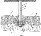
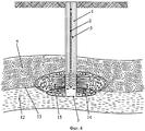
На фиг.1 представлена схема реализации данного способа при очистке забоя от жидкости и механических примесей, на фиг.2 - то же при закачивании в интервал перфорации первой пачки гидрофобизирующего состава, на фиг.3 - то же при закачивании в интервал перфорации второй пачки гидрофобизирующего состава, на фиг.4 - то же при закачивании в интервал ГВК гидрофобной кремнеорганической жидкости.Figure 1 presents a diagram of the implementation of this method when cleaning the face from liquid and mechanical impurities, figure 2 - the same when pumping into the perforation interval of the first packet of water-repellent composition, figure 3 - the same when pumping into the perforation interval of the second packet of water-repellent composition, figure 4 is the same when pumping into the interval GVK hydrophobic organosilicon liquid.
Способ реализуется следующим образом.The method is implemented as follows.
В газовую скважину, находящуюся под давлением, во внутреннюю полость ЛК 1 газовой скважины спускают ГТ 2 до забоя 3. Проводят очистку забоя 3 от жидкости и механических примесей прямой циркуляцией газового конденсата с выпуском газа, находящегося в скважине, на факел, с заполнением ствола скважины газовым конденсатом.
После чего приподнимают ГТ 2 до башмака ЛК 1. Закачивают в интервал перфорации 4 через КП 5 между ГТ 2 и ЛК 1 первую пачку гидрофобизирующего состава 6, содержащего этилсиликат ЭТС-40 10%-ной концентрации, играющего роль гидрофобизирующей добавки, в газовом конденсате в объеме 1-2 м3 на каждый метр газонасыщенной 7 толщины пласта 8 с продавливанием его в газонасыщенную часть 7 пласта 8 буферной пачкой 9 газового конденсата в объеме 0,2 м3 и образованием в продуктивном пласте 8 водоизоляционного экрана 10, оттесняющего пластовые воды от забоя 3 в глубину пласта 8 по радиусу.Then they lift
Закачивают через КП 5 в интервал перфорации 4 вторую пачку гидрофобизирующего состава 11, содержащего этилсиликат ЭТС-40 100%-ной концентрации, играющую роль гелеобразователя, в объеме 0,4-0,6 м3 на каждый метр эффективной, включающей газонасыщенную 7 и водонасыщенную 12 части, толщины пласта 8, продавливают его в пласт 8 газоконденсатом в объеме ЛК 1 и внутреннего пространства скважины, ее эксплуатационной колонны, ниже башмака ЛК 1.A second pack of hydrophobizing
Далее ГТ 2 доспускают в интервал ГВК 13, положение которого определяют геофизическими методами, и закачивают через нее гидрофобную кремнеорганическую жидкость 14 ГКЖ-11Н, играющую роль закрепителя, в объеме 0,10-0,15 м3 на каждый метр водонасыщенную 12 толщины пласта 8, образующую при контакте с водой водонасыщенной части 12 пласта 8 блокирующий экран 15, препятствующий поступлению воды к забою скважины.Next,
Затем проводят обратную промывку скважины в объеме 2,0 цикла с противодавлением. ГТ 2 извлекают из скважины и скважину оставляют на реагирование под давлением.Then backwash the wells in a volume of 2.0 cycles with back pressure.
Примеры реализации способа.Examples of the method.
Необходимо провести изоляцию притока пластовой воды в газовой скважине с аномально-низкими пластовыми давлениями без ее глушения.It is necessary to isolate the inflow of formation water in a gas well with abnormally low formation pressures without killing it.
ЭТС-40 или этилсиликат - кремнийорганическое соединение, содержащее католические добавки органохлорсиланов: тетраэтоксисилана и соляной кислоты (HCl). При гидролизе этилсиликата образуется гель, и продукт гидролиза закупоривает породу. Состав обладает высокой водоизолирующей способностью и избирательным воздействием на нефтеводонасыщенные пласты.ETS-40 or ethyl silicate is an organosilicon compound containing Catholic additives of organochlorosilanes: tetraethoxysilane and hydrochloric acid (HCl). Upon hydrolysis of ethyl silicate, a gel forms and the hydrolysis product clogs the rock. The composition has a high water-insulating ability and selective effect on oil-saturated formations.
ГКЖ являются продуктами гидролиза органотрихлорсиланов с последующим растворением продуктов гидролиза в водном или водоспиртовом растворе щелочи (едкого натрия).GKZH are the products of the hydrolysis of organotrichlorosilanes with the subsequent dissolution of the products of hydrolysis in an aqueous or aqueous-alcoholic solution of alkali (sodium hydroxide).
Данные составы могут использоваться в широком интервале пластовых температур от нуля до 200°C независимо от степени минерализации пластовых вод. Температура замерзания - ниже минус 40°C.These compositions can be used in a wide range of reservoir temperatures from zero to 200 ° C, regardless of the degree of mineralization of formation waters. Freezing point - below minus 40 ° C.
Содержание ЭТС-40 в составе газового конденсата более 10% нецелесообразно из-за возрастания стоимости, связанной с повышенным расходом реагентов, при этом заметного улучшения технологических параметров не наблюдается.The content of ETS-40 in the composition of gas condensate of more than 10% is impractical due to the increase in cost associated with increased consumption of reagents, while there is no noticeable improvement in technological parameters.
При содержании ГКЖ-11Н в ЭТС-40 более 15% значительно сокращает время полимеризации, что может привести к невозможности закачивания водоизоляционной композиции в пласт.When the content of GKZH-11N in ETS-40 is more than 15%, it significantly reduces the polymerization time, which can lead to the inability to pump the waterproofing composition into the reservoir.
При содержании ГКЖ-11Н в ЭТС-40 менее 5% значительно возрастает время процесса полимеризации (24-48 ч), что экономически не оправдано при проведении водоизоляционных работ.When the content of GKZH-11N in ETS-40 is less than 5%, the polymerization process time significantly increases (24-48 hours), which is not economically justified when conducting waterproofing works.
При обратной промывке скважины в объеме менее 2,0 циклов возрастают риски прихвата гибкой трубы в лифтовой колонне, а в объеме более 2,0 циклов обратная промывка экономически не целесообразна, так как не приводит к заметному увеличению эффекта.When backwashing a well in a volume of less than 2.0 cycles, the risks of sticking a flexible pipe in an elevator string increase, and in a volume of more than 2.0 cycles, backwashing is not economically feasible, since it does not lead to a noticeable increase in the effect.
При закачивании первой пачки ЭТС-40 в объеме меньше 1 м3 на каждый метр газонасыщенной толщины пласта снижается эффективность проведения водоизоляционных работ, а при объеме больше 2 м3 значительно сокращается время полимеризации, что может привести к невозможности закачки последующей водоизоляционной композиции в пласт.When pumping the first pack of ETS-40 in a volume of less than 1 m 3 for each meter of gas-saturated thickness of the reservoir, the effectiveness of water insulation works decreases, and with a volume of more than 2 m 3 the polymerization time is significantly reduced, which can lead to the inability to pump the subsequent waterproofing composition into the reservoir.
При закачивании второй пачки ЭТС-40 в объеме меньше 0,4 м3 на каждый метр эффективной толщины пласта, которая слагается из газонасыщенной и вскрытой водонасыщенной частей пласта, снижается эффективность водоизоляционных работ, а при объеме больше 0,6 м3 значительно сокращается время полимеризации, что может привести к невозможности закачки водоизоляционной композиции в пласт.When pumping a second pack of ETS-40 in a volume of less than 0.4 m 3 for each meter of the effective thickness of the formation, which is composed of gas-saturated and exposed water-saturated parts of the formation, the efficiency of waterproofing works is reduced, and with a volume of more than 0.6 m 3 the polymerization time is significantly reduced , which can lead to the inability to pump the waterproofing composition into the reservoir.
При закачивании ГКЖ-11Н в объеме меньше 0,10 м3 на каждый метр эффективной толщины пласта снижается эффективность водоизоляционных работ, при объеме больше 0,15 м3 значительно сокращается время полимеризации, что может привести к невозможности закачки водоизоляционной композиции в пласт.When injecting GKZh-11N in a volume of less than 0.10 m 3 for each meter of effective thickness of the formation, the effectiveness of water insulation works decreases, with a volume of more than 0.15 m 3 the polymerization time is significantly reduced, which can lead to the inability to pump the waterproofing composition into the formation.
Пример №1Example No. 1
В газовую скважину, находящуюся под давлением, глубиной 1000 м во внутреннюю полость ЛК диаметром 168 мм спускают ГТ диаметром 48 мм до забоя. Проводят очистку забоя от жидкости и механических примесей. Приподнимают ГТ до башмака ЛК. Закачивают в интервал перфорации длиной 60 м через КП площадью 15853,86 мм2 первую пачку гидрофобизирующего состава, содержащего ЭТС-40 10%-ной концентрации в газовом конденсате в объеме 60 м с образованием водоизоляционного экрана. Закачивают через КП вначале газовый конденсат в объеме 0,2 м3, а вслед за ним вторую пачку гидрофобизирующего состава, содержащий ЭТС-40 100%-ной концентрации в объеме 24 м, продавливают его в пласт газоконденсатом в объеме ЛК и внутреннего пространства скважины ниже ЛК. Далее ГТ доспускают в интервал ГВК и закачивают через нее гидрофобную кремнеорганическую жидкость ГКЖ-11Н в объеме 10,0 м3. Затем проводят обратную промывку скважины в объеме 2,0 цикла с противодавлением 5,0 МПа. ГТ извлекают из скважины и скважину оставляют на реагирование под давлением.In a gas well, which is under pressure, with a depth of 1000 m, GTs with a diameter of 48 mm are lowered into the internal cavity of an LC with a diameter of 168 mm to the bottom. The bottom is cleaned from liquid and solids. Lift the GT to the boot shoe. The first pack of water-repellent composition containing ETS-40 of 10% concentration in gas condensate in a volume of 60 m is pumped into a 60-meter-long perforation interval through a KP of 15853.86 mm 2 with the formation of a waterproofing screen. First, gas condensate is pumped through the KP in a volume of 0.2 m 3 , and after it a second pack of water-repellent composition containing ETS-40 of 100% concentration in a volume of 24 m is pumped into the formation by gas condensate in the volume of the well and the interior of the well below LK. Next, GT is allowed into the GWC interval and GKZh-11N hydrophobic organosilicon fluid is pumped through it in a volume of 10.0 m 3 . Then a backwash of the well is carried out in a volume of 2.0 cycles with a back pressure of 5.0 MPa. GT is removed from the well and the well is left to react under pressure.
Пример №2Example No. 2
В газовую скважину, находящуюся под давлением, глубиной 1200 м во внутреннюю полость ЛК диаметром 114 мм спускают ГТ диаметром 42 мм до забоя. Проводят очистку забоя от жидкости и механических примесей. Приподнимают ГТ до башмака ЛК. Закачивают в интервал перфорации длиной 30 м через КП площадью 6465,86 мм2 первую пачку гидрофобизирующего состава, содержащего ЭТС-40 10%-ной концентрации в газовом конденсате в объеме 45 м3 с образованием водоизоляционного экрана. Закачивают через КП вначале газовый конденсат, а вслед за ним вторую пачку гидрофобизирующего состава, содержащего ЭТС-40 100%-ной концентрации в объеме 15 м3, продавливают его в пласт газоконденсатом в объеме ЛК и внутреннего пространства скважины ниже ЛК. Далее ГТ доспускают в интервал ГВК и закачивают через нее гидрофобную кремнеорганическую жидкость ГКЖ-11Н в объеме 12,0 м3. Затем проводят обратную промывку скважины в объеме 2,0 цикла с противодавлением 5,5 МПа. ГТ извлекают из скважины и скважину оставляют на реагирование под давлением.In a gas well, which is under pressure, with a depth of 1200 m, GTs with a diameter of 42 mm are lowered into the internal cavity of a laser cutting chamber with a diameter of 114 mm to the bottom. The bottom is cleaned from liquid and solids. Lift the GT to the boot shoe. The first pack of hydrophobizing composition containing ETS-40 of 10% concentration in gas condensate in a volume of 45 m 3 is pumped into a 30 m long perforation interval through a KP with an area of 6465.86 mm 2 to form a waterproofing screen. First, gas condensate is pumped through the KP, and then a second pack of hydrophobizing composition containing ETS-40 of 100% concentration in a volume of 15 m 3 is pumped, gas condensate is pushed into the formation in the volume of the well and the interior of the well below the well. Next, GT is allowed into the GWC interval and GKZh-11N hydrophobic organosilicon fluid is pumped through it in a volume of 12.0 m 3 . Then a backwash of the well is carried out in a volume of 2.0 cycles with a back pressure of 5.5 MPa. GT is removed from the well and the well is left to react under pressure.
Пример №3Example No. 3
В газовую скважину, находящуюся под давлением, глубиной 1400 м во внутреннюю полость ЛК диаметром 89 мм спускают ГТ диаметром 33 мм до забоя. Проводят очистку забоя от жидкости и механических примесей. Приподнимают ГТ до башмака ЛК. Закачивают в интервал перфорации длиной 10 м через КП площадью 3921,07 мм2 первую пачку гидрофобизирующего состава, содержащего ЭТС-40 10%-ной концентрации в газовом конденсате в объеме 20 м3 с образованием водоизоляционного экрана. Закачивают через КП вначале газовый конденсат, а вслед за ним вторую пачку гидрофобизирующего состава, содержащего ЭТС-40 100%-ной концентрации в объеме 6 м3, продавливают его в пласт газоконденсатом в объеме ЛК и внутреннего пространства скважины ниже ЛК. Далее ГТ доспускают в интервал ГВК и закачивают через нее гидрофобную кремнеорганическую жидкость ГКЖ-11Н в объеме 15,0 м3. Затем проводят обратную промывку скважины в объеме 2,0 цикла с противодавлением 6,0 МПа. ГТ извлекают из скважины и скважину оставляют на реагирование под давлением.In a gas well, which is under pressure, with a depth of 1400 m, GT 33 mm in diameter is lowered into the internal cavity of the LC 89 mm in diameter to the bottom. The bottom is cleaned from liquid and solids. Lift the GT to the boot shoe. The first pack of hydrophobizing composition containing ETS-40 of 10% concentration in gas condensate in a volume of 20 m 3 is pumped into a 10 m long perforation interval through a KP with an area of 3921.07 mm 2 to form a waterproofing screen. First, gas condensate is pumped through the KP, and then a second pack of water-repellent composition containing ETS-40 of 100% concentration in a volume of 6 m 3 is pumped, gas condensate is pushed into the formation in the volume of the well and the interior of the well below the well. Next, GT is allowed into the GWC interval and GKZh-11N hydrophobic organosilicon fluid is pumped through it in a volume of 15.0 m 3 . Then a backwash of the well is carried out in a volume of 2.0 cycles with a back pressure of 6.0 MPa. GT is removed from the well and the well is left to react under pressure.
Предлагаемый способ изоляции притока пластовых вод в скважинах позволяет проводить ремонтно-изоляционные работы без глушения скважины, снизить степень загрязнения призабойной зоны пласта, сохранить газонасыщенную толщину пласта, сократить продолжительность ремонтных работ в 5-6 раз, снизить затраты на проведение работ и стоимость ремонта скважины в 3-4 раза.The proposed method of isolating the influx of formation water in the wells allows for repair and insulation work without killing the well, to reduce the degree of contamination of the bottom-hole zone of the formation, to preserve the gas-saturated thickness of the formation, to reduce the duration of repair work by 5-6 times, to reduce the cost of the work and the cost of repairing the well in 3-4 times.
Claims (1)
Priority Applications (1)
| Application Number | Priority Date | Filing Date | Title |
|---|---|---|---|
| RU2013134912/03A RU2534373C1 (en) | 2013-07-23 | 2013-07-23 | Method for shutoff of stratal water influx |
Applications Claiming Priority (1)
| Application Number | Priority Date | Filing Date | Title |
|---|---|---|---|
| RU2013134912/03A RU2534373C1 (en) | 2013-07-23 | 2013-07-23 | Method for shutoff of stratal water influx |
Publications (1)
| Publication Number | Publication Date |
|---|---|
| RU2534373C1 true RU2534373C1 (en) | 2014-11-27 |
Family
ID=53383030
Family Applications (1)
| Application Number | Title | Priority Date | Filing Date |
|---|---|---|---|
| RU2013134912/03A RU2534373C1 (en) | 2013-07-23 | 2013-07-23 | Method for shutoff of stratal water influx |
Country Status (1)
| Country | Link |
|---|---|
| RU (1) | RU2534373C1 (en) |
Cited By (2)
| Publication number | Priority date | Publication date | Assignee | Title |
|---|---|---|---|---|
| CN115163027A (en) * | 2021-04-02 | 2022-10-11 | 中国石油化工股份有限公司 | Method for treating water coning or ridge entering at bottom of oil well |
| US12180416B2 (en) | 2020-01-21 | 2024-12-31 | Limited Liability Company “Gr Petroleum” | Method for preventing stratal water from breaking through into bottom holes of wells |
Citations (7)
| Publication number | Priority date | Publication date | Assignee | Title |
|---|---|---|---|---|
| US4503912A (en) * | 1983-06-13 | 1985-03-12 | Marathon Oil Company | Process for conformance control using a polymer flocculate |
| RU2211311C2 (en) * | 2001-01-15 | 2003-08-27 | ООО Научно-исследовательский институт "СибГеоТех" | Method of simultaneous-separate development of several productive formations and well unit for method embodiment |
| RU2228437C2 (en) * | 2002-04-01 | 2004-05-10 | Дыбленко Валерий Петрович | Method for isolation of water influx, gas influx or lost circulation zones |
| RU2244115C1 (en) * | 2003-06-09 | 2005-01-10 | Общество с ограниченной ответственностью "ТюменНИИгипрогаз" | Method of insulating formation water inflow |
| RU2333348C2 (en) * | 2006-09-15 | 2008-09-10 | Государственное образовательное учреждение высшего профессионального образования "Тюменский государственный нефтегазовый университет" | Method of dry operation of wells |
| RU2415258C1 (en) * | 2010-06-07 | 2011-03-27 | Открытое акционерное общество "Татнефть" им. В.Д. Шашина | Procedure for treatment of bottomhole zone of producer |
| RU2480581C1 (en) * | 2011-08-29 | 2013-04-27 | Общество с ограниченной ответственностью "Газпром добыча Ямбург" | Method to isolate inflow of reservoir water in low-angle and horizontal wells |
-
2013
- 2013-07-23 RU RU2013134912/03A patent/RU2534373C1/en not_active IP Right Cessation
Patent Citations (7)
| Publication number | Priority date | Publication date | Assignee | Title |
|---|---|---|---|---|
| US4503912A (en) * | 1983-06-13 | 1985-03-12 | Marathon Oil Company | Process for conformance control using a polymer flocculate |
| RU2211311C2 (en) * | 2001-01-15 | 2003-08-27 | ООО Научно-исследовательский институт "СибГеоТех" | Method of simultaneous-separate development of several productive formations and well unit for method embodiment |
| RU2228437C2 (en) * | 2002-04-01 | 2004-05-10 | Дыбленко Валерий Петрович | Method for isolation of water influx, gas influx or lost circulation zones |
| RU2244115C1 (en) * | 2003-06-09 | 2005-01-10 | Общество с ограниченной ответственностью "ТюменНИИгипрогаз" | Method of insulating formation water inflow |
| RU2333348C2 (en) * | 2006-09-15 | 2008-09-10 | Государственное образовательное учреждение высшего профессионального образования "Тюменский государственный нефтегазовый университет" | Method of dry operation of wells |
| RU2415258C1 (en) * | 2010-06-07 | 2011-03-27 | Открытое акционерное общество "Татнефть" им. В.Д. Шашина | Procedure for treatment of bottomhole zone of producer |
| RU2480581C1 (en) * | 2011-08-29 | 2013-04-27 | Общество с ограниченной ответственностью "Газпром добыча Ямбург" | Method to isolate inflow of reservoir water in low-angle and horizontal wells |
Cited By (2)
| Publication number | Priority date | Publication date | Assignee | Title |
|---|---|---|---|---|
| US12180416B2 (en) | 2020-01-21 | 2024-12-31 | Limited Liability Company “Gr Petroleum” | Method for preventing stratal water from breaking through into bottom holes of wells |
| CN115163027A (en) * | 2021-04-02 | 2022-10-11 | 中国石油化工股份有限公司 | Method for treating water coning or ridge entering at bottom of oil well |
Similar Documents
| Publication | Publication Date | Title |
|---|---|---|
| RU2460876C1 (en) | Method for performing pulse hydraulic fracturing of carbonate formation | |
| RU2460875C1 (en) | Carbonate formation hydraulic fracturing method | |
| RU2485296C1 (en) | Method for improvement of hydrodynamic communication of well with productive formation | |
| RU2544343C1 (en) | Hydraulic fracturing method for low-permeable bed with clay layers and bottom water | |
| RU2483209C1 (en) | Method of hydraulic fracturing of well formation | |
| RU2531775C1 (en) | Seam hydro frac in well | |
| RU2512216C1 (en) | Treatment method of bottomhole zone | |
| RU2526062C1 (en) | Multiple hydraulic fracturing of formation in well horizontal shaft | |
| CN100516457C (en) | Chemical pulse compound plugging removal method | |
| RU2490442C1 (en) | Method for well completion | |
| RU2522366C1 (en) | Method of hydraulic fracturing of well formation | |
| RU2485306C1 (en) | Method of hydraulic fracturing of well formation | |
| RU2566357C1 (en) | Method of formation hydraulic fracturing | |
| RU2534373C1 (en) | Method for shutoff of stratal water influx | |
| RU2447265C1 (en) | Method for horizontal well operation | |
| RU2550638C1 (en) | Hydraulic fracturing method for low-permeable formation with impermeable layer and water-bearing interlayer | |
| RU2599156C1 (en) | Method of interval treatment of bottom hole zone of horizontal well shaft | |
| RU2571964C1 (en) | Hydrofracturing method for formation in well | |
| RU2569941C2 (en) | Bottom water isolation method | |
| RU2459072C1 (en) | Method of hydraulic fracturing of low-permeable formation of injection well | |
| RU2254443C1 (en) | Method for isolation of non-pressurized range of column in a well | |
| RU2610967C1 (en) | Method of selective treatment of productive carbonate formation | |
| RU2527434C1 (en) | Bottomhole zone treatment method for horizontal well | |
| RU2564312C1 (en) | Method of deposit hydraulic fracturing in well | |
| RU2580532C2 (en) | Isolation method of brine water influx in well |
Legal Events
| Date | Code | Title | Description |
|---|---|---|---|
| MM4A | The patent is invalid due to non-payment of fees |
Effective date: 20160724 |