RU2533990C2 - Method and device for loading to melting unit - Google Patents
Method and device for loading to melting unit Download PDFInfo
- Publication number
- RU2533990C2 RU2533990C2 RU2012120086/02A RU2012120086A RU2533990C2 RU 2533990 C2 RU2533990 C2 RU 2533990C2 RU 2012120086/02 A RU2012120086/02 A RU 2012120086/02A RU 2012120086 A RU2012120086 A RU 2012120086A RU 2533990 C2 RU2533990 C2 RU 2533990C2
- Authority
- RU
- Russia
- Prior art keywords
- semi
- finished product
- iron
- reducing gas
- feeding
- Prior art date
Links
Images
Classifications
-
- C—CHEMISTRY; METALLURGY
- C21—METALLURGY OF IRON
- C21B—MANUFACTURE OF IRON OR STEEL
- C21B3/00—General features in the manufacture of pig-iron
-
- C—CHEMISTRY; METALLURGY
- C21—METALLURGY OF IRON
- C21B—MANUFACTURE OF IRON OR STEEL
- C21B13/00—Making spongy iron or liquid steel, by direct processes
- C21B13/0086—Conditioning, transformation of reduced iron ores
- C21B13/0093—Protecting against oxidation
-
- C—CHEMISTRY; METALLURGY
- C21—METALLURGY OF IRON
- C21B—MANUFACTURE OF IRON OR STEEL
- C21B13/00—Making spongy iron or liquid steel, by direct processes
- C21B13/14—Multi-stage processes processes carried out in different vessels or furnaces
- C21B13/143—Injection of partially reduced ore into a molten bath
-
- F—MECHANICAL ENGINEERING; LIGHTING; HEATING; WEAPONS; BLASTING
- F27—FURNACES; KILNS; OVENS; RETORTS
- F27D—DETAILS OR ACCESSORIES OF FURNACES, KILNS, OVENS, OR RETORTS, IN SO FAR AS THEY ARE OF KINDS OCCURRING IN MORE THAN ONE KIND OF FURNACE
- F27D3/00—Charging; Discharging; Manipulation of charge
- F27D3/0025—Charging or loading melting furnaces with material in the solid state
-
- C—CHEMISTRY; METALLURGY
- C21—METALLURGY OF IRON
- C21B—MANUFACTURE OF IRON OR STEEL
- C21B2100/00—Handling of exhaust gases produced during the manufacture of iron or steel
- C21B2100/20—Increasing the gas reduction potential of recycled exhaust gases
-
- C—CHEMISTRY; METALLURGY
- C21—METALLURGY OF IRON
- C21B—MANUFACTURE OF IRON OR STEEL
- C21B2100/00—Handling of exhaust gases produced during the manufacture of iron or steel
- C21B2100/60—Process control or energy utilisation in the manufacture of iron or steel
-
- Y—GENERAL TAGGING OF NEW TECHNOLOGICAL DEVELOPMENTS; GENERAL TAGGING OF CROSS-SECTIONAL TECHNOLOGIES SPANNING OVER SEVERAL SECTIONS OF THE IPC; TECHNICAL SUBJECTS COVERED BY FORMER USPC CROSS-REFERENCE ART COLLECTIONS [XRACs] AND DIGESTS
- Y02—TECHNOLOGIES OR APPLICATIONS FOR MITIGATION OR ADAPTATION AGAINST CLIMATE CHANGE
- Y02P—CLIMATE CHANGE MITIGATION TECHNOLOGIES IN THE PRODUCTION OR PROCESSING OF GOODS
- Y02P10/00—Technologies related to metal processing
- Y02P10/10—Reduction of greenhouse gas [GHG] emissions
- Y02P10/134—Reduction of greenhouse gas [GHG] emissions by avoiding CO2, e.g. using hydrogen
Abstract
Description
Данное изобретение относится к способу и устройству для загрузки полуфабриката в плавильный агрегат для чугуна. This invention relates to a method and apparatus for loading a semi-finished product into a cast iron smelter.
В способе восстановления тонкоизмельченной железной руды, как, например, в FINEX®-способе, производят прямое восстановление железа (direct reduced iron, DRI) в реакторе кипящего слоя посредством восстановительных газов. Это напрямую восстановленное железо имеет степень восстановления приблизительно 50~95% в зависимости от метода производства и применяемой тонкоизмельченной железной руды. Для полного восстановления и для производства чугуна проводят прямое восстановление железа DRI после этапа компактирования, при котором получают так называемое горячекомпактированное железо (hot compacted iron, HCI), подаваемое в накопитель или загрузочное устройство, по которому проходит при необходимости восстановительный газ, и оттуда в плавильный агрегат, такой как, например, газификатор плавления. Накопитель, названный также HCI-Bin, или загрузочное устройство выполняет в том числе функцию накопителя для обеспечения непрерывной загрузки горячекомпактированного железа в плавильный агрегат. Далее он предоставляет возможность подогревать загружаемые материалы, как, например, гранулы или куски руды или кокс, восстановительным газом в плавильном агрегате. При этом накопитель расположен у плавильного агрегата, чтобы обеспечить возможность загрузки из накопителя в плавильный агрегат под действием силы тяжести. Преобладающую часть полученного на этапе компактирования горячекомпактированного железа в нормальном режиме работы FINEX®-установки подводят после компактирования непосредственно в горячем состоянии в накопитель или загрузочное устройство. Другую часть полученного на этапе компактирования горячекомпактированного железа используют в нормальном режиме работы FINEX®-установки после компактирования, чтобы заложить вне накопителя или загрузочного устройства хранимый запас компактированного железа. Этот запас компактированного железа необходим, к примеру, во время запуска или низкого хода FINEX®-установки. Согласно уровню техники это не непосредственно перенесенное в накопитель горячекомпактированное железо обычно резко охлаждают в закалочной емкости с водой и хранят под открытым небом при атмосферных условиях. Как только это охлажденное хранимое компактированное железо необходимо для подачи в плавильный агрегат, его подводят в накопитель или загрузочное устройство. В нем его подогревают перед его загрузкой в плавильный агрегат.In the reduction method of finely divided iron ore, as, for example, in the FINEX® method, direct reduction of iron (direct reduced iron, DRI) is carried out in a fluidized bed reactor by means of reducing gases. This directly reduced iron has a reduction rate of approximately 50 ~ 95% depending on the production method and the finely ground iron ore used. For complete reduction and for the production of pig iron, direct reduction of DRI iron is carried out after the compacting stage, in which the so-called hot compacted iron (HCI) is obtained, which is supplied to a storage device or loading device, through which, if necessary, reducing gas passes, and from there to the melting an aggregate, such as, for example, a melting gasifier. A storage device, also called HCI-Bin, or a loading device, also serves as a storage device for continuously loading hot-compacted iron into the melting unit. Further, it provides the opportunity to heat the feed materials, such as granules or pieces of ore or coke, with reducing gas in the smelter. In this case, the accumulator is located near the melting unit in order to provide the possibility of loading from the accumulator into the melting unit under the action of gravity. The predominant part of the hot compacted iron obtained at the compacting stage in the normal operation mode of the FINEX® installation is fed after compacting directly in the hot state to the drive or loading device. Another part of the hot compacted iron obtained during the compacting step is used in the normal operation of the FINEX® installation after compacting in order to store the stored stock of compacted iron outside the drive or loading device. This stock of compacted iron is needed, for example, during start-up or low-speed FINEX® installations. According to the state of the art, this hot-compacted iron that is not directly transferred to the storage ring is usually sharply cooled in a quenching tank with water and stored outdoors under atmospheric conditions. As soon as this refrigerated stored compacted iron is needed to be fed into the melting unit, it is fed to a storage device or loading device. In it, it is heated before loading it into the melting unit.
Вместе с тем невыгодно, что охлажденное в закалочной емкости компактированное железо при хранении склонно к обратному окислению и при его подогреве перед загрузкой в плавильный агрегат необходимы высокие затраты энергии. Необходимое для подогрева материала время увеличивает, кроме того, продолжительность пускового процесса. Далее, функционирование закалочного оборудования затратно и приводит к расходам времени и средств на обслуживание и утилизацию отходов холоднобрикетированного железа и шламов. Следует ожидать больших затрат вовлекаемых инвестиций при использовании. Те же условия также считаются само собой разумеющимися, если используют не FINEX®-способ с HCI в качестве полуфабриката, а способ, при котором из окисленного источника железа производят железные брикеты (hot briquetted iron, HBI) в качестве брикетированного, что также называют компактированным, полуфабриката. At the same time, it is disadvantageous that the compacted iron cooled in the quenching tank during storage is prone to reverse oxidation and when it is heated before loading into the melting unit, high energy costs are required. The time required for heating the material increases, in addition, the duration of the starting process. Further, the operation of quenching equipment is costly and leads to time and money spent on the maintenance and disposal of cold briquetted iron and sludge waste. Expected high costs of the investment involved in use. The same conditions are also taken for granted if you do not use the FINEX® method with HCI as a semi-finished product, but the method in which iron briquettes (hot briquetted iron, HBI) are produced from the oxidized iron source, which is also called compacted, semi-finished product.
Также при некомпактированном исходном сырье, таком как низковосстановленное железо (low reduced iron, LRI), это соответствующим образом невыгодно хранить полуфабрикат не в горячем состоянии. Also, with uncompacted feedstocks such as low reduced iron (LRI), it is accordingly disadvantageous to store the semi-finished product not in a hot state.
Поэтому задачей данного изобретения является предоставление способа и устройства для производства чугуна из полуфабриката, не имеющих упомянутых недостатков. Therefore, the objective of the invention is the provision of a method and device for the production of cast iron from semi-finished products that do not have the mentioned disadvantages.
Эта задача решается посредством способа производства чугуна в плавильном агрегате из полуфабриката, полученного восстановлением окисленного источника железа первым восстановительным газом, причем полуфабрикат загружают из непосредственно соединенного с плавильным агрегатом накопителя или загрузочного устройства, из которого осуществляют подачу в плавильный агрегат, отличающегося тем, что часть полуфабриката сохраняют в горячем состоянии в накопительном бункере, прежде чем происходит его введение в накопитель или загрузочное устройство, непосредственно связанные с плавильным агрегатом.This problem is solved by a method for producing pig iron in a smelting unit from a semi-finished product obtained by reducing an oxidized iron source by a first reducing gas, the semi-finished product being loaded from a storage device or loading device directly connected to the melting unit, from which a part of the semi-finished product is supplied to the melting unit kept hot in the storage hopper before it is introduced into the drive or boot device oystvo directly related to the melting aggregate.
Окисленный источник железа преобразуют восстановлением посредством первого восстановительного газа в полуфабрикат для производства чугуна, к примеру, в непосредственно восстановленное железо DRI. Если продукт восстановления является не кусковым, а тонкоизмельченным, то он может для улучшения удобства использования подвергаться компактированию посредством устройств для компактирования, которые включают машину компактирования и дробильную систему. Часть полуфабриката сохраняют в накопительном бункере, прежде чем происходит его введение в непосредственно связанный с накопителем или загрузочным устройством плавильный агрегат. При этом полуфабрикат железа охлаждают не закалкой, а сохраняют в горячем состоянии в накопительном бункере. Если происходит компактирование, то полуфабрикат сохраняют после проведенного компактирования в накопительном бункере. Таким образом, в случае загрузки в плавильный агрегат подогрева этого материала не требуется. The oxidized iron source is converted by reduction by means of the first reducing gas into a prefabricated iron product, for example, directly reduced iron DRI. If the recovery product is not lumpy but finely divided, then it can be compacted by means of compacting devices, which include a compacting machine and a crushing system, to improve usability. Part of the semi-finished product is stored in the storage hopper before it is introduced into the melting unit directly connected to the drive or loading device. In this case, the semi-finished iron is not cooled by quenching, but is kept hot in the storage hopper. If compacting occurs, the semi-finished product is stored after compacting in the storage hopper. Thus, in the case of loading into the melting unit, heating of this material is not required.
Подача хранящегося в накопительном бункере полуфабриката в накопитель или загрузочное устройство может происходить во время пускового процесса. Она может происходить также во время нормальной эксплуатации, чтобы добавкой полуфабриката в накопитель или загрузочное устройство сгладить количественные отклонения при производстве полуфабриката. The feed of the semi-finished product stored in the storage hopper to the drive or loading device may occur during the starting process. It can also occur during normal operation, so that the addition of the semi-finished product to the drive or loading device to smooth out the quantitative deviations in the production of the semi-finished product.
Накопитель и загрузочное устройство нужно рассматривать как эквивалентные, так как оба устройства подходят для принятия доставленного полуфабриката перед подачей в плавильный агрегат, и соответственно доставленный материал пребывает промежуток времени перед подачей в плавильный агрегат в загрузочном устройстве, прежде чем он попадает в плавильный агрегат, так как прохождение загрузочного устройства требует определенного времени. В это время материал находится в загрузочном устройстве и сохраняется таким образом в нем. The drive and the loading device should be considered equivalent, since both devices are suitable for accepting the delivered semi-finished product before being fed to the melting unit, and accordingly the delivered material remains a period of time before being fed to the melting unit in the loading device before it enters the melting unit, since It takes time for the boot device to go through. At this time, the material is in the boot device and is thus stored in it.
В различных вариантах осуществления соответствующего изобретению способа окисленным источником железа является тонкоизмельченная железная руда или кусковая руда, или гранулы.In various embodiments of the method of the invention, the oxidized source of iron is finely divided iron ore or lump ore or granules.
В одном из вариантов осуществления соответствующего изобретению способа полуфабрикатом является горячекомпактированное железо.In one embodiment of the method according to the invention, the semi-finished product is hot compacted iron.
Обычно говорят, к примеру, о горячекомпактированном железе HCI, если плотность исходного сырья составляет менее 4,5 кг/дм3, а металлизация <88%. HCI содержит при необходимости добавки.Usually they say, for example, about the hot-compacted iron HCI, if the density of the feedstock is less than 4.5 kg / dm 3 and the metallization is <88%. HCI contains additives as needed.
В одном из вариантов осуществления соответствующего изобретению способа исходным сырьем является горячебрикетированное железо HBI. Обычно говорят, к примеру, о горячебрикетируемом железе, если плотность полуфабриката составляет более 5 кг/дм3, а его металлизация более 88%. HBI не содержит обычно добавок. В одном из вариантов осуществления соответствующего изобретению способа полуфабрикатом является горячее низковосстановленное железо.In one embodiment of the method of the invention, the feedstock is HBI hot briquette iron. Usually they say, for example, hot-briquetted iron, if the density of the semi-finished product is more than 5 kg / dm 3 and its metallization is more than 88%. HBI usually does not contain additives. In one embodiment of the process according to the invention, the semi-finished product is hot low-reduced iron.
Преимущественно хранимый в горячем состоянии в накопительном бункере полуфабрикат обдувают защитным газом от вторичного окисления, который замедляет вторичное окисление полуфабриката. Таким образом, можно препятствовать вторичному окислению, выраженному, в крайнем случае, как сгорание, во время хранения в накопительном бункере. В качестве защитного газа от вторичного окисления рассматривается, к примеру, инертный газ, как например, азот или восстановительный газ, об этом восстановительном газе может идти речь, к примеру, как о первом восстановительном газе или в дальнейшем также как о вводимом втором восстановительном газе. Preferably stored in a hot state in the storage bin, the semi-finished product is blown with a protective gas from secondary oxidation, which slows down the secondary oxidation of the semi-finished product. Thus, it is possible to prevent secondary oxidation, expressed, as a last resort, as combustion, during storage in the storage hopper. As a protective gas from secondary oxidation, for example, an inert gas, such as nitrogen or a reducing gas, is considered, this reducing gas can be considered, for example, as the first reducing gas or hereinafter also referred to as the introduced second reducing gas.
Соответственно потенциальная угроза безопасности сокращена при проведении соответствующего изобретению способа по сравнению с уровнем техники. Неокислительная, то есть, к примеру, инертная или восстановительная, атмосфера в накопительном бункере препятствует вторичному окислению полуфабриката и уменьшает отрицательные воздействия на плавильный агрегат благодаря использованию полуфабриката с низкой или резко колеблющейся степенью восстановления.Accordingly, the potential security risk is reduced when carrying out the method according to the invention in comparison with the prior art. The non-oxidizing, that is, for example, inert or reducing, atmosphere in the storage hopper prevents the secondary oxidation of the semi-finished product and reduces the negative effects on the melting unit due to the use of the semi-finished product with a low or sharply fluctuating degree of reduction.
В одном из вариантов осуществления соответствующего изобретению способа второй восстанавливающий газ проходит по непосредственно соединенному с плавильным агрегатом накопителю или загрузочному устройству. In one embodiment of the method of the invention, the second reducing gas passes through a drive or loading device directly connected to the melting unit.
В предпочтительном варианте осуществления изобретения первый восстанавливающий газ и второй восстанавливающий газ происходят из одного источника, к примеру плавильного агрегата, как например газификатора плавления. Таким образом, сокращается количество необходимых устройств для предоставления восстанавливающих газов. In a preferred embodiment of the invention, the first reducing gas and the second reducing gas come from a single source, for example a melting unit, such as a melting gasifier. Thus, the number of necessary devices for providing reducing gases is reduced.
Преимущественно подача из накопителя или загрузочного устройства в плавильный агрегат происходит, по существу, силой тяжести. Таким образом, аппаратурные и энергетические затраты для доставки полуфабриката из накопителя или загрузочного устройства в плавильный агрегат малы. Однако, в принципе, подача может происходить навстречу силе тяжести, к примеру так, что накопитель или загрузочное устройство находится ниже питающего отверстия для подачи исходного сырья в плавильный агрегат и должно отправляться оттуда наверх, навстречу силе тяжести, к питающему отверстию. Также питающее отверстие и накопитель или загрузочное устройство могут находиться относительно друг друга на высоте, причем полуфабрикат из накопителя или загрузочного устройства должен доставляться сбоку в питающее отверстие не в направлении силы тяжести. Для доставки сбоку или сверху требуется больше энергии и аппаратурных затрат, чем для подачи, которая происходит вниз, по существу, под действием силы тяжести. При этом формулировка "по существу" означает, что дополнительно к боковой доставке может производиться подача верхней доставкой добавочных материалов, к примеру, если отверстие, из которого полуфабрикат покидает накопитель или загрузочное устройство, расположено не вертикально относительно питающего отверстия, через которое его добавляют в плавильный агрегат.Advantageously, the feed from the storage ring or loading device to the melting unit takes place essentially by gravity. Thus, the hardware and energy costs for delivering the semi-finished product from the drive or loading device to the melting unit are small. However, in principle, the feed can occur against gravity, for example, so that the drive or loading device is below the feed opening for supplying the feedstock to the melting unit and must be sent upward from there, towards gravity, to the feed hole. Also, the feed opening and the drive or loading device may be relatively high relative to each other, and the semi-finished product from the drive or loading device should be delivered laterally to the supply hole in the direction of gravity. For delivery from the side or from above, more energy and hardware are required than for delivery, which occurs downward, essentially due to gravity. Moreover, the wording “essentially” means that in addition to lateral delivery, additional materials may be delivered by overhead delivery, for example, if the hole from which the semifinished product leaves the drive or loading device is not vertically relative to the feed hole through which it is added to the melting unit.
Другим объектом данного изобретения является устройство для осуществления способа по любому из пп.1-10, по меньшей мере, с одним восстановительным агрегатом для восстановления окисленного источника железа посредством первого восстановительного газа, вводимого в восстановительный агрегат первым трубопроводом восстановительного газа, одним агрегатом плавления для производства чугуна из полученного восстановлением первым восстановительным газом окисленного источника железа полуфабриката, и одним питателем для подачи полуфабриката в накопитель или устройство подачи, которое соединено с плавильным агрегатом по меньшей мере одним подающим трубопроводом, и причем имеется завалочное устройство для подачи полуфабриката в питатель, отличающееся тем, что имеется накопительный бункер для хранения полуфабриката в горячем состоянии, а также питающее устройство для питания полуфабрикатом накопительного бункера, причем накопительный бункер также соединен с питателем.Another object of this invention is a device for implementing the method according to any one of claims 1 to 10, with at least one reducing unit for reducing an oxidized iron source by means of a first reducing gas introduced into the reducing unit by a first reducing gas pipe, one melting unit for production pig iron from the oxidized iron source of the semi-finished product obtained by reduction by the first reducing gas, and one feeder for feeding the semi-finished product to a storage device or feeding device, which is connected to the melting unit with at least one feeding pipe, and there is a filling device for feeding the semi-finished product to the feeder, characterized in that there is a storage hopper for storing the semi-finished product in a hot state, as well as a feeding device for feeding the semi-finished product hopper, and the storage hopper is also connected to the feeder.
Окисленный источник железа восстанавливают по меньшей мере в одном восстановительном агрегате, который может быть выполнен, к примеру, в виде реактора кипящего слоя или в виде восстановительной шахты неподвижного слоя, посредством первого восстановительного газа. Используемый для восстановления первый восстановительный газ подают посредством впадающего в восстановительный агрегат первого трубопровода восстановительного газа.The oxidized source of iron is reduced in at least one reduction unit, which can be performed, for example, in the form of a fluidized bed reactor or in the form of a fixed shaft recovery shaft, by means of a first reducing gas. The first reducing gas used for the reduction is supplied by means of the first reducing gas conduit flowing into the recovery unit.
Подающий трубопровод, который впадает в питающее отверстие плавильного агрегата, может быть также частью загрузочного устройства.The feed line that flows into the feed opening of the smelter may also be part of the loading device.
Восстановительный агрегат может быть, к примеру, реактором неподвижного слоя или реактором кипящего слоя.The recovery unit may be, for example, a fixed bed reactor or a fluidized bed reactor.
Полуфабрикат, полученный восстановлением окисленного источника железа, при необходимости компактированный или брикетированный, загружают посредством устройства подачи в питатель для подачи полуфабриката. Устройство подачи может быть, к примеру, течкой, шнеком, транспортным желобом или трубой. Посредством питателя для подачи полуфабриката, к примеру горячего транспортера, полуфабрикат транспортируют в накопитель или загрузочное устройство.The semifinished product obtained by reducing the oxidized iron source, optionally compacted or briquetted, is loaded by means of a feeding device into the feeder for feeding the semifinished product. The feed device may be, for example, a estrus, auger, transport chute or pipe. By means of a feeder for supplying a semi-finished product, for example a hot conveyor, the semi-finished product is transported to a drive or loading device.
Накопитель или загрузочное устройство соединено с плавильным агрегатом подающим трубопроводом, через который происходит подача полуфабриката из накопителя или загрузочного устройства непосредственно в плавильный агрегат. Естественно, в подающем трубопроводе могут иметься дополнительные устройства, к примеру клапаны или шлюзы. Питающий трубопровод впадает в питающее отверстие плавильного агрегата, которым он выходит из накопителя для материала в плавильный агрегат. Далее, соответствующее изобретению устройство имеет накопитель для хранения полуфабриката в горячем состоянии. Он соединен как с питателем для питания полуфабрикатом накопительного бункера, так и питающим устройством. Питателем является, к примеру, напорная труба, течка, горячий транспортер, шнековый транспортер, барабанный ячейковый питатель. Поэтому полуфабрикат может подаваться в накопительный бункер, а из накопительного бункера в устройство подачи, к примеру, через шнековый транспортер, барабанный ячейковый питатель, промежуточный горячий транспортер, клапан, трубу, течку.The storage device or loading device is connected to the melting unit by a supply pipe through which the semi-finished product is fed from the storage device or loading device directly to the melting unit. Naturally, in the supply pipe there may be additional devices, for example valves or locks. The feed pipe flows into the feed opening of the melting unit, by which it exits from the material store to the melting unit. Further, the device according to the invention has a storage device for storing the semi-finished product in a hot state. It is connected both with a feeder for feeding the semi-finished product of the storage hopper, and with a feeding device. The feeder is, for example, a pressure pipe, estrus, hot conveyor, screw conveyor, drum cell feeder. Therefore, the semi-finished product can be fed into the storage hopper, and from the storage hopper to the feed device, for example, through a screw conveyor, a drum cell feeder, an intermediate hot conveyor, valve, pipe, estrus.
Накопитель облицован огнеупорным материалом. Его емкость должна покрывать целесообразный расход полуфабриката, к примеру, горячекомпактированного железа HCI, для примерно от 12-24-часового до двухдневного срока работы устройства для осуществления способа согласно изобретению. К примеру, расход 4600 т HCI соответствует объему накопителя примерно 2×900 м3.The drive is lined with refractory material. Its capacity should cover the appropriate consumption of the semi-finished product, for example, hot-compacted iron HCI, for from about 12-24 hours to a two-day life of the device for implementing the method according to the invention. For example, a consumption of 4600 t of HCI corresponds to a storage volume of approximately 2 × 900 m 3 .
В варианте изобретения имеется устройство компактирования для компактирования и/или брикетирования, причем устройство компактирования находится между восстановительным агрегатом и подающим устройством и между восстановительным агрегатом и питающим устройством. Устройство компактирования соединено при этом соответственно с обеими сторонами устройства, между которыми оно находится, при этом "между" следует понимать относительно потока материала от восстанавливающего агрегата к плавильному агрегату. Извлеченный из восстановительного агрегата материал, к примеру DRI, компактируют в устройстве компактирования, охватывающем машину компактирования и дробильную систему. При этом образуется в качестве полуфабриката, к примеру, горячекомпактированное железо HCI или горячебрикетированное железо HBI.In an embodiment of the invention, there is a compacting device for compacting and / or briquetting, wherein the compacting device is located between the recovery unit and the feeding device and between the recovery unit and the feeding device. In this case, the compacting device is connected respectively to both sides of the device between which it is located, while the “between” should be understood with respect to the material flow from the reducing unit to the melting unit. The material recovered from the recovery unit, for example DRI, is compacted in a compacting device covering the compacting machine and the crushing system. When this is formed as a semi-finished product, for example, hot-compacted iron HCI or hot-briquette iron HBI.
В этом случае предпочтительно, чтобы имелось в наличии загрузочное устройство для задания компактированного и/или брикетированного полуфабриката из устройства компактирования в устройство подачи, и чтобы накопитель был соединен с устройством компактирования через устройство ввода к вводу компактированного и/или брикетированного полуфабриката из устройства компактирования в накопитель.In this case, it is preferable that there is a boot device for defining the compacted and / or briquetted cake mix from the compacting device to the feed device, and that the drive is connected to the compacting device through an input device to input the compacted and / or briquetted cake mix from the compacting device to the drive .
В варианте осуществления изобретения в накопитель или загрузочное устройство впадает второй трубопровод восстановительного газа. Благодаря контакту с ним через вводимый второй восстановительный газ материал, который находится в накопителе или загрузочном устройстве, при необходимости, частично восстанавливается и соответственно подогревается. При этом первый трубопровод восстановительного газа и второй трубопровод восстановительного газа соединены при помощи агрегата для получения восстановительного газа, причем в варианте осуществления изобретения первый трубопровод восстановительного газа и второй трубопровод восстановительного газа соединены с одним и тем же агрегатом для получения восстановительного газа.In an embodiment of the invention, a second reducing gas conduit flows into the accumulator or loading device. Due to contact with it through the introduced second reducing gas, the material, which is located in the storage device or loading device, is partially restored, if necessary, and heated accordingly. In this case, the first reducing gas pipeline and the second reducing gas pipeline are connected by means of a reducing gas generating unit, in an embodiment of the invention, the first reducing gas pipeline and the second reducing gas pipeline are connected to the same unit for receiving reducing gas.
Агрегат для получения восстановительного газа следует рассматривать в качестве источника восстановительного газа. Преимущественно трубопровод защитного газа от вторичного окисления впадает в поток защитного газа накопителя. Таким образом, находящийся в накопителе горячий полуфабрикат, к примеру горячекомпактированное железо HCI, можно защитить от вторичного окисления.A unit for producing reducing gas should be considered as a source of reducing gas. Advantageously, the secondary gas oxidation shield gas flows into the shield gas stream. In this way, the hot semi-finished product in the drive, for example the hot compacted iron HCI, can be protected from secondary oxidation.
В варианте осуществления изобретения накопительный бункер расположен на более низкой высоте, к примеру, на уровне земли, чем питающее отверстие плавильного агрегата. Вследствие этого получается экономия основного и вспомогательного материала и стальных конструкций при строительстве накопительного бункера и, соответственно, при строительстве опорных конструкций накопительного бункера. В варианте осуществления изобретения плавильным агрегатом является газификатор плавления. Может также идти речь о доменной печи.In an embodiment of the invention, the storage hopper is located at a lower height, for example, at ground level than the feed opening of the melting unit. As a result of this, savings are obtained in the main and auxiliary material and steel structures during the construction of the storage hopper and, accordingly, in the construction of the supporting structures of the storage hopper. In an embodiment, the melting unit is a melter gasifier. It may also be a blast furnace.
По сравнению с проводимой согласно уровню техники закалкой исходного сырья, как например HCI, согласно изобретению перед хранением имеется преимущество, что никакой влажный закаленный полуфабрикат, как например HCI, не смешивается с горячим полуфабрикатом, как например HCI, вследствие чего сокращается опасность взрыва от образующегося водорода. Далее, согласно варианту изобретения приобретение или производство закалочных емкостей для охлаждения исходного сырья больше не требуется. Вместе с тем можно сократить необходимое для способа количество воды.Compared to prior art quenching of feedstocks, such as HCI, according to the invention, there is an advantage over storage that no wet hardened semi-finished product, such as HCI, is mixed with a hot semi-finished product, such as HCI, thereby reducing the risk of explosion from the generated hydrogen . Further, according to an embodiment of the invention, the purchase or production of quenching tanks for cooling the feedstock is no longer required. However, you can reduce the amount of water required for the method.
Следующее преимущество данного изобретения состоит в том, что накопитель или загрузочное устройство, как например HCI-Bin, может быть малогабаритным, так как материал амортизации при изменении производства полуфабриката должен находиться не в HCI-Bin, а может быть изъят из накопительного бункера. Вместе с тем снижаются материальные затраты и затраты труда при строительстве HCI-Bin, а также его габаритная высота. Преимущественно имеется по меньшей мере два накопительных бункера, чтобы иметь возможность использовать резервный бункер при ремонтных работах. Полуфабрикат из накопительного бункера может подаваться также к нескольким различным плавильным агрегатам, к примеру к газификатору плавления и к доменной печи.A further advantage of this invention is that the drive or loading device, such as HCI-Bin, can be small-sized, since the depreciation material should not be in the HCI-Bin when changing the production of the semi-finished product, but may be removed from the storage hopper. At the same time, material and labor costs during the construction of HCI-Bin, as well as its overall height, are reduced. Advantageously, there are at least two storage hoppers in order to be able to use the backup hopper for repair work. The semi-finished product from the storage hopper can also be fed to several different smelting units, for example, to the melting gasifier and to the blast furnace.
Далее, данное изобретение подробнее разъясняется посредством двух схематически показанных на фигурах вариантов изобретения.Further, the present invention is explained in more detail by means of two schematically illustrated embodiments of the invention.
Фигура 1 показывает схематическую структуру соответствующего изобретению устройства с реактором кипящего слоя.Figure 1 shows a schematic structure of a fluidized bed reactor apparatus of the invention.
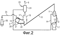
Фигура 2 показывает схематическую структуру соответствующего изобретению устройства с реактором неподвижного слоя.Figure 2 shows a schematic structure of a device of the invention with a fixed bed reactor.
Тонкоизмельченную железную руду 1 подают в каскад реакторов кипящего слоя 2а, 2b, 2с. Первый восстановительный газ вводят через первый трубопровод восстановительного газа 3 в реактор кипящего слоя 2с, после которого через соединительный трубопровод 4 вводят в реактор кипящего слоя 2b, после которого через соединительный трубопровод 5 вводят в реактор кипящего слоя 2а и из него выводят через трубопровод отходящего газа 6. Первый трубопровод восстановительного газа 3 берет начало в плавильном агрегате 7, в котором из горячекомпактированного железа производят чугун. Изъятый из реактора кипящего слоя 2с продукт компактируют в горячекомпактированное железо посредством компактирующего устройства, которое охватывает промежуточный бункер 8, машину компактирования 9а и дробильную систему 9b. Горячекомпактированное железо HCI-bin располагают у подающего устройства 10 накопителя 11. HCI-bin расположено над газификатором плавления 7. Накопитель 11 соединен с газификатором плавления 7 через питающий трубопровод 12, через который горячекомпактированное HCI следует под действием силы тяжести из накопителя 11 в газификатор плавления 7. Питающий трубопровод 12 впадает питающим отверстием 13 в газификатор плавления 7. Второй трубопровод восстановительного газа 14 впадает в накопитель 11, вытекает из газификатора плавления 7.Fine iron ore 1 is fed into the cascade of fluidized bed reactors 2a, 2b, 2c. The first reducing gas is introduced through the first reducing
Непосредственная подача горячекомпактированного железа из дробильной системы 9b происходит посредством загрузочного устройства, которое представлено на фигуре посредством течки 15 исходящего трубопровода 16.Direct supply of the hot compacted iron from the crushing system 9b takes place via a loading device, which is shown in the figure by estrus 15 of the
Произведенное в устройстве компактирования горячекомпактированное железо соответствующей установкой течки 15 может быть введено через трубопровод 17 и горячий транспортер 18 представленного устройства ввода непосредственно в накопительный бункер 19. Через впадающий в один из накопительных бункеров 19 трубопровод 20 защитного газа от вторичного окисления вводят инертный газ азот в накопительный бункер 19.The hot-compacted iron produced in the compacting device by an appropriate heat installation 15 can be introduced through the
Верх трубопровода резервного вывода 21 и горячий транспортер 22 соединен накопительным бункером 19 с подающим устройством 10. Таким образом, можно отбирать необходимое количество горячекомпактированного железа из накопительного бункера 19 и подавать в накопитель 11.The top of the
На фигуре 2 соответствующие элементы конструкции фигуры 1 снабжены теми же условными обозначениями, как на фигуре 1. Фигура 2 отличается от фигуры 1 применением вместо реакторов кипящего слоя реактора неподвижного слоя 24 в качестве агрегата восстановления. В него в качестве окисленного источника железа 23 вводят куски руды или гранулы. Реактор неподвижного слоя соединен с первым трубопроводом восстановительного газа 3, через который проходит первый восстановительный газ.In figure 2, the corresponding structural elements of figure 1 are provided with the same conventions as in figure 1. Figure 2 differs from figure 1 by using a fixed
Использованный восстановительный газ выпускают через трубопровод отходящего газа 6. Полуфабрикат подводят из реактора неподвижного слоя 24 либо через трубопровод 16 подающего устройства 10, либо подводят через трубопровод 17 горячего транспортера 18, через который поддерживают горячий полуфабрикат в накопительном бункере 19. Полуфабрикат может подаваться из накопительного бункера 19 через отводящий трубопровод 25 в доменную печь 26.The used reducing gas is discharged through the
Список условных обозначенийLegend List
1 - тонкоизмельченная железная руда1 - finely ground iron ore
2а, 2b, 2с - реакторы кипящего слоя2a, 2b, 2c - fluidized bed reactors
3 - первый трубопровод восстановительного газа3 - the first pipeline of reducing gas
4 - соединительный трубопровод4 - connecting pipe
5 - соединительный трубопровод5 - connecting pipe
6 - трубопровод отходящего газа6 - exhaust gas pipeline
7 - газификатор плавления7 - melting gasifier
8 - промежуточный бункер8 - intermediate hopper
9а - машина компактирования9a - compacting machine
9b - дробильная система9b - crushing system
10 - подающее устройство10 - feeding device
11 - накопитель11 - drive
12 - питающий трубопровод12 - supply pipe
13 - питающее отверстие13 - feeding hole
14 - второй трубопровод восстановительного газа14 - second pipeline of reducing gas
15 - течка15 - estrus
16 - трубопровод16 - pipeline
17 - трубопровод17 - pipeline
18 - горячий транспортер18 - hot conveyor
19 - накопительный бункер19 - storage hopper
20 - трубопровод защитного газа от вторичного окисления20 - shielding gas pipe from secondary oxidation
21 - трубопровод резервного вывода21 - backup output pipe
22 - горячий транспортер22 - hot conveyor
23 - окисленный источник железа23 - oxidized source of iron
24 - реактор неподвижного слоя24 - fixed bed reactor
25 - отводящий трубопровод25 - discharge pipe
26 - доменная печь26 - blast furnace
Claims (19)
получение горячего полуфабриката восстановлением окисленного источника железа первым восстановительным газом, и
загрузку полуфабриката в плавильный агрегат из непосредственно соединенного с плавильным агрегатом накопителя или загрузочного устройства,
отличающийся тем, что часть полуфабриката сохраняют в горячем состоянии в накопительном бункере перед его подачей в накопитель или загрузочное устройство, непосредственно связанное с плавильным агрегатом.1. Method for the production of pig iron in a smelter, including
obtaining a hot semi-finished product by reducing the oxidized iron source by the first reducing gas, and
loading the semi-finished product into the melting unit from a drive or loading device directly connected to the melting unit,
characterized in that part of the semi-finished product is kept hot in the storage hopper before it is fed to the drive or loading device directly connected to the melting unit.
один восстановительный агрегат для восстановления окисленного источника железа посредством первого восстановительного газа,
первый трубопровод для ввода восстановительного газа (3) в восстановительный агрегат,
плавильный агрегат для производства чугуна из полуфабриката, полученного восстановлением первым восстановительным газом окисленного носителя железа, и
подающее устройство (10) для подачи полуфабриката в непосредственно связанный с плавильным агрегатом накопитель (11) или загрузочное устройство, с по меньшей мере одним питающим трубопроводом (12), причем питающее отверстие (13) питающего трубопровода (12) входит в плавильный агрегат, и
причем имеется завалочное устройство для подачи полуфабриката в подающее устройство (10), характеризующееся тем, что оно
содержит накопительный бункер (19) для хранения части полуфабриката в горячем состоянии, а также питающее устройство для подачи части полуфабриката в накопительный бункер (19), причем накопительный бункер (19) также соединен с подающим устройством (10).11. A device for the production of pig iron in a smelter by the method according to any one of claims 1 to 10, containing at least
one reducing unit for reducing an oxidized iron source by means of a first reducing gas,
a first pipeline for introducing reducing gas (3) into the reducing unit,
a smelter for the production of cast iron from a semi-finished product obtained by the reduction of an oxidized iron support with a first reducing gas, and
a feeding device (10) for feeding the semi-finished product to a storage device (11) directly connected to the melting unit or a loading device, with at least one feeding pipe (12), wherein the feeding hole (13) of the feeding pipe (12) is included in the melting unit, and
moreover, there is a filling device for feeding the semi-finished product to the feeding device (10), characterized in that it
contains a storage hopper (19) for storing part of the semi-finished product in a hot state, as well as a feeding device for feeding part of the semi-finished product to the storage hopper (19), and the storage hopper (19) is also connected to the feeding device (10).
Applications Claiming Priority (3)
| Application Number | Priority Date | Filing Date | Title |
|---|---|---|---|
| AT0163609A AT508953B1 (en) | 2009-10-16 | 2009-10-16 | METHOD AND DEVICE FOR CHARGING IN A FILLING UNIT |
| ATA1636/2009 | 2009-10-16 | ||
| PCT/EP2010/064867 WO2011045212A1 (en) | 2009-10-16 | 2010-10-06 | Method and device for feeding into a smelting unit |
Publications (2)
| Publication Number | Publication Date |
|---|---|
| RU2012120086A RU2012120086A (en) | 2013-11-27 |
| RU2533990C2 true RU2533990C2 (en) | 2014-11-27 |
Family
ID=43428772
Family Applications (1)
| Application Number | Title | Priority Date | Filing Date |
|---|---|---|---|
| RU2012120086/02A RU2533990C2 (en) | 2009-10-16 | 2010-10-06 | Method and device for loading to melting unit |
Country Status (13)
| Country | Link |
|---|---|
| US (2) | US8728384B2 (en) |
| EP (1) | EP2488810A1 (en) |
| JP (1) | JP2013507527A (en) |
| KR (1) | KR101724268B1 (en) |
| CN (1) | CN102612632B (en) |
| AT (1) | AT508953B1 (en) |
| AU (1) | AU2010305955B2 (en) |
| BR (1) | BR112012008905B1 (en) |
| CA (1) | CA2777654C (en) |
| IN (1) | IN2012DN02795A (en) |
| RU (1) | RU2533990C2 (en) |
| UA (1) | UA106508C2 (en) |
| WO (1) | WO2011045212A1 (en) |
Families Citing this family (3)
| Publication number | Priority date | Publication date | Assignee | Title |
|---|---|---|---|---|
| KR101187851B1 (en) * | 2010-11-19 | 2012-10-04 | 주식회사 포스코 | Apparatus for manufacturing molten iron and method for manufacturing thereof |
| CN104648892B (en) * | 2014-01-17 | 2016-09-07 | 柳州钢铁股份有限公司 | The straight feeding device of sintering deposit |
| US11427877B2 (en) | 2017-09-21 | 2022-08-30 | Nucor Corporation | Direct reduced iron (DRI) heat treatment, products formed therefrom, and use thereof |
Citations (3)
| Publication number | Priority date | Publication date | Assignee | Title |
|---|---|---|---|---|
| EP0515744A1 (en) * | 1991-05-30 | 1992-12-02 | HYLSA, S.A. de C.V. | Method for the transport of sponge iron |
| EP0364865B1 (en) * | 1988-10-17 | 1993-09-08 | METALLGESELLSCHAFT Aktiengesellschaft | Method for producing steel from ore fines |
| RU2311464C2 (en) * | 2002-12-21 | 2007-11-27 | Поско | Unit for production of molten cast iron by hot molding of ground reduced iron and calcined additives and method of use of this unit |
Family Cites Families (13)
| Publication number | Priority date | Publication date | Assignee | Title |
|---|---|---|---|---|
| JPH07103410B2 (en) | 1990-02-02 | 1995-11-08 | 日本鋼管株式会社 | Pressure stabilization device for pressurized smelting reduction furnace in smelting reduction equipment |
| CN1037192C (en) * | 1991-06-03 | 1998-01-28 | 伊尔萨公司 | Method for transport of sponge iron |
| JP3403093B2 (en) | 1998-10-21 | 2003-05-06 | 三菱重工業株式会社 | Method and equipment for producing reduced iron |
| AT408991B (en) | 2000-04-28 | 2002-04-25 | Voest Alpine Ind Anlagen | METHOD AND SYSTEM FOR PRODUCING A METAL MELT |
| CN1325666C (en) * | 2002-12-21 | 2007-07-11 | Posco公司 | An apparatus for manufacturing molten irons by hot compacting fine direct reduced irons and calcined additives and method using the same |
| UA88283C2 (en) * | 2003-10-21 | 2009-10-12 | Оутокумпу Текнолоджи Ой | Plant and process for direct smelting for producing molten iron from fine fractions of iron ore |
| CN1243004C (en) | 2003-12-01 | 2006-02-22 | 中国海洋大学 | Tricycloacetal lactones ,preparing process and use thereof |
| BRPI0414335B8 (en) * | 2003-12-05 | 2017-05-23 | Posco | cast iron fabrication method, integrated steel fabrication method, cast iron fabrication equipment and integrated steel mill |
| WO2006011774A1 (en) * | 2004-07-30 | 2006-02-02 | Posco | Apparatus for manufacturing molten irons by injecting fine coals into a melter-gasifier and the method using the same. |
| EP1802780B1 (en) * | 2004-10-19 | 2011-06-22 | Posco | Apparatus for manufacturing compacted irons of reduced materials comprising fine direct reduced irons and apparatus for manufacturing molten irons using the same |
| JP5323378B2 (en) * | 2008-03-28 | 2013-10-23 | 株式会社神戸製鋼所 | Raw material input device for manufacturing molten iron and raw material input method for manufacturing molten iron |
| WO2009144521A2 (en) * | 2008-04-17 | 2009-12-03 | Hyl Technolohies, S.A. De C.V. | Steelmaking facility comprising a direct reduction plant and an electric-arc furnace |
| AT506837B1 (en) | 2008-06-06 | 2010-03-15 | Siemens Vai Metals Tech Gmbh | METHOD AND DEVICE FOR PRODUCING RAW STEEL OR LIQUID STEEL PREPARATIONS |
-
2009
- 2009-10-16 AT AT0163609A patent/AT508953B1/en active
-
2010
- 2010-10-06 AU AU2010305955A patent/AU2010305955B2/en active Active
- 2010-10-06 KR KR1020127012560A patent/KR101724268B1/en active IP Right Grant
- 2010-10-06 CA CA2777654A patent/CA2777654C/en active Active
- 2010-10-06 US US13/502,282 patent/US8728384B2/en active Active
- 2010-10-06 JP JP2012533571A patent/JP2013507527A/en active Pending
- 2010-10-06 IN IN2795DEN2012 patent/IN2012DN02795A/en unknown
- 2010-10-06 BR BR112012008905A patent/BR112012008905B1/en active IP Right Grant
- 2010-10-06 CN CN201080046646.3A patent/CN102612632B/en active Active
- 2010-10-06 WO PCT/EP2010/064867 patent/WO2011045212A1/en active Application Filing
- 2010-10-06 UA UAA201204641A patent/UA106508C2/en unknown
- 2010-10-06 EP EP10765415A patent/EP2488810A1/en not_active Withdrawn
- 2010-10-06 RU RU2012120086/02A patent/RU2533990C2/en active
-
2014
- 2014-03-06 US US14/198,697 patent/US9365906B2/en active Active
Patent Citations (3)
| Publication number | Priority date | Publication date | Assignee | Title |
|---|---|---|---|---|
| EP0364865B1 (en) * | 1988-10-17 | 1993-09-08 | METALLGESELLSCHAFT Aktiengesellschaft | Method for producing steel from ore fines |
| EP0515744A1 (en) * | 1991-05-30 | 1992-12-02 | HYLSA, S.A. de C.V. | Method for the transport of sponge iron |
| RU2311464C2 (en) * | 2002-12-21 | 2007-11-27 | Поско | Unit for production of molten cast iron by hot molding of ground reduced iron and calcined additives and method of use of this unit |
Non-Patent Citations (1)
| Title |
|---|
| КУРУНОВ И.Ф. и др. Состояние и перспективы бездоменной металлургии железа., М.: Черметинформация, 2002, cc.126-128 * |
Also Published As
| Publication number | Publication date |
|---|---|
| CA2777654C (en) | 2017-08-22 |
| US20140196571A1 (en) | 2014-07-17 |
| BR112012008905A8 (en) | 2018-06-12 |
| KR101724268B1 (en) | 2017-04-07 |
| CA2777654A1 (en) | 2011-04-21 |
| RU2012120086A (en) | 2013-11-27 |
| UA106508C2 (en) | 2014-09-10 |
| IN2012DN02795A (en) | 2015-07-24 |
| EP2488810A1 (en) | 2012-08-22 |
| AT508953A1 (en) | 2011-05-15 |
| AU2010305955B2 (en) | 2013-06-27 |
| US8728384B2 (en) | 2014-05-20 |
| JP2013507527A (en) | 2013-03-04 |
| US9365906B2 (en) | 2016-06-14 |
| BR112012008905B1 (en) | 2020-04-14 |
| AU2010305955A1 (en) | 2012-04-19 |
| KR20120094928A (en) | 2012-08-27 |
| CN102612632A (en) | 2012-07-25 |
| AT508953B1 (en) | 2011-07-15 |
| US20120279356A1 (en) | 2012-11-08 |
| BR112012008905A2 (en) | 2018-05-02 |
| CN102612632B (en) | 2014-09-24 |
| WO2011045212A1 (en) | 2011-04-21 |
Similar Documents
| Publication | Publication Date | Title |
|---|---|---|
| KR101128939B1 (en) | An apparatus for manufacturing a molten iron directly using fine or lump coals and fine iron ores, the method thereof, the integrated steel mill using the same and the method thereof | |
| EP2409101B1 (en) | Steel production facility | |
| RU2434948C2 (en) | Procedure and system for supply of hot iron of direct reduction for numerous consumers | |
| JPS61502899A (en) | Continuous steel making process and equipment | |
| RU2008125843A (en) | METHOD FOR PRODUCING MELTED CAST IRON AND INSTALLATION FOR PRODUCING MELTED CAST IRON | |
| RU2533990C2 (en) | Method and device for loading to melting unit | |
| CN103221555B (en) | Apparatus for manufacturing molten iron and method for manufacturing molten iron using same | |
| KR101550893B1 (en) | Method and apparatus for manufacturing molten iron | |
| WO2005054520A1 (en) | An apparatus for manufacturing a molten iron directly using fine or lump coals and fine iron ores, the method thereof, the integrated steel mill using the same and the method thereof | |
| JP2004538363A (en) | Method and apparatus for performing carbon-based metallurgy | |
| Sampaio et al. | Hot metal strategies for the EAF industry | |
| US4464197A (en) | Method for making iron by induction heating | |
| KR101607254B1 (en) | Combiner Ironmaking facilities | |
| CN210711618U (en) | System for adding scrap steel to molten iron bearing equipment by adopting belt conveyor | |
| RU2143006C1 (en) | Method of mounting aggregate for reduction melting process at producing conversion cast iron, aggregate for performing reduction melting process, method for producing conversion cast iron | |
| US8961648B2 (en) | Integrated steel plant with production of hot or cold DRI | |
| CN115125348B (en) | Method and system for efficiently using metallized pellets of rotary hearth furnace | |
| US20220403481A1 (en) | System and method for the production of hot briquetted iron (hbi) containing flux and/or carbonaceous material at a direct reduction plant | |
| Hillisch et al. | Status of FINMET plant operation at BHP DRI, Australia (January 2001) | |
| Klein et al. | New installations, new directions and new results at CST’s ironmaking area | |
| Olayebi | REMODIFICATION IN THE OXIDE FEED SYSTEM FOR MIDREX DIRECT REDUCTION SHAFT FURNACE OF THE DELTA STEEL COMPANY | |
| Kurunov et al. | Blast furnace no. 6 at the Novolipetsk Metallurgical Combine–the best Russian design. | |
| Grobler | The Increasing Role of Direct Reduced Iron (DRI) in Global Steelmaking |
Legal Events
| Date | Code | Title | Description |
|---|---|---|---|
| PC43 | Official registration of the transfer of the exclusive right without contract for inventions |
Effective date: 20160803 |
|
| TC4A | Change in inventorship |
Effective date: 20181025 |
|
| PC41 | Official registration of the transfer of exclusive right |
Effective date: 20190125 |