RU2530833C2 - Event-controlled method of user training to detect analyte in body fluid sample - Google Patents
Event-controlled method of user training to detect analyte in body fluid sample Download PDFInfo
- Publication number
- RU2530833C2 RU2530833C2 RU2007133237/12A RU2007133237A RU2530833C2 RU 2530833 C2 RU2530833 C2 RU 2530833C2 RU 2007133237/12 A RU2007133237/12 A RU 2007133237/12A RU 2007133237 A RU2007133237 A RU 2007133237A RU 2530833 C2 RU2530833 C2 RU 2530833C2
- Authority
- RU
- Russia
- Prior art keywords
- training
- display
- event
- user
- training images
- Prior art date
Links
Images


Classifications
-
- A—HUMAN NECESSITIES
- A61—MEDICAL OR VETERINARY SCIENCE; HYGIENE
- A61B—DIAGNOSIS; SURGERY; IDENTIFICATION
- A61B5/00—Measuring for diagnostic purposes; Identification of persons
- A61B5/15—Devices for taking samples of blood
- A61B5/150007—Details
- A61B5/150175—Adjustment of penetration depth
- A61B5/150198—Depth adjustment mechanism at the proximal end of the carrier of the piercing element
-
- A—HUMAN NECESSITIES
- A61—MEDICAL OR VETERINARY SCIENCE; HYGIENE
- A61B—DIAGNOSIS; SURGERY; IDENTIFICATION
- A61B5/00—Measuring for diagnostic purposes; Identification of persons
- A61B5/145—Measuring characteristics of blood in vivo, e.g. gas concentration, pH value; Measuring characteristics of body fluids or tissues, e.g. interstitial fluid, cerebral tissue
- A61B5/14532—Measuring characteristics of blood in vivo, e.g. gas concentration, pH value; Measuring characteristics of body fluids or tissues, e.g. interstitial fluid, cerebral tissue for measuring glucose, e.g. by tissue impedance measurement
-
- A—HUMAN NECESSITIES
- A61—MEDICAL OR VETERINARY SCIENCE; HYGIENE
- A61B—DIAGNOSIS; SURGERY; IDENTIFICATION
- A61B5/00—Measuring for diagnostic purposes; Identification of persons
- A61B5/15—Devices for taking samples of blood
- A61B5/150007—Details
- A61B5/150015—Source of blood
- A61B5/150022—Source of blood for capillary blood or interstitial fluid
-
- A—HUMAN NECESSITIES
- A61—MEDICAL OR VETERINARY SCIENCE; HYGIENE
- A61B—DIAGNOSIS; SURGERY; IDENTIFICATION
- A61B5/00—Measuring for diagnostic purposes; Identification of persons
- A61B5/15—Devices for taking samples of blood
- A61B5/150007—Details
- A61B5/150206—Construction or design features not otherwise provided for; manufacturing or production; packages; sterilisation of piercing element, piercing device or sampling device
- A61B5/150259—Improved gripping, e.g. with high friction pattern or projections on the housing surface or an ergonometric shape
-
- A—HUMAN NECESSITIES
- A61—MEDICAL OR VETERINARY SCIENCE; HYGIENE
- A61B—DIAGNOSIS; SURGERY; IDENTIFICATION
- A61B5/00—Measuring for diagnostic purposes; Identification of persons
- A61B5/15—Devices for taking samples of blood
- A61B5/150007—Details
- A61B5/150206—Construction or design features not otherwise provided for; manufacturing or production; packages; sterilisation of piercing element, piercing device or sampling device
- A61B5/150305—Packages specially adapted for piercing devices or blood sampling devices
-
- A—HUMAN NECESSITIES
- A61—MEDICAL OR VETERINARY SCIENCE; HYGIENE
- A61B—DIAGNOSIS; SURGERY; IDENTIFICATION
- A61B5/00—Measuring for diagnostic purposes; Identification of persons
- A61B5/15—Devices for taking samples of blood
- A61B5/150007—Details
- A61B5/150358—Strips for collecting blood, e.g. absorbent
-
- A—HUMAN NECESSITIES
- A61—MEDICAL OR VETERINARY SCIENCE; HYGIENE
- A61B—DIAGNOSIS; SURGERY; IDENTIFICATION
- A61B5/00—Measuring for diagnostic purposes; Identification of persons
- A61B5/15—Devices for taking samples of blood
- A61B5/150007—Details
- A61B5/150374—Details of piercing elements or protective means for preventing accidental injuries by such piercing elements
- A61B5/150381—Design of piercing elements
- A61B5/150412—Pointed piercing elements, e.g. needles, lancets for piercing the skin
-
- A—HUMAN NECESSITIES
- A61—MEDICAL OR VETERINARY SCIENCE; HYGIENE
- A61B—DIAGNOSIS; SURGERY; IDENTIFICATION
- A61B5/00—Measuring for diagnostic purposes; Identification of persons
- A61B5/15—Devices for taking samples of blood
- A61B5/150007—Details
- A61B5/150374—Details of piercing elements or protective means for preventing accidental injuries by such piercing elements
- A61B5/150381—Design of piercing elements
- A61B5/150503—Single-ended needles
-
- A—HUMAN NECESSITIES
- A61—MEDICAL OR VETERINARY SCIENCE; HYGIENE
- A61B—DIAGNOSIS; SURGERY; IDENTIFICATION
- A61B5/00—Measuring for diagnostic purposes; Identification of persons
- A61B5/15—Devices for taking samples of blood
- A61B5/150007—Details
- A61B5/150374—Details of piercing elements or protective means for preventing accidental injuries by such piercing elements
- A61B5/150534—Design of protective means for piercing elements for preventing accidental needle sticks, e.g. shields, caps, protectors, axially extensible sleeves, pivotable protective sleeves
- A61B5/150541—Breakable protectors, e.g. caps, shields or sleeves, i.e. protectors separated destructively, e.g. by breaking a connecting area
- A61B5/150549—Protectors removed by rotational movement, e.g. torsion or screwing
-
- A—HUMAN NECESSITIES
- A61—MEDICAL OR VETERINARY SCIENCE; HYGIENE
- A61B—DIAGNOSIS; SURGERY; IDENTIFICATION
- A61B5/00—Measuring for diagnostic purposes; Identification of persons
- A61B5/15—Devices for taking samples of blood
- A61B5/150007—Details
- A61B5/150374—Details of piercing elements or protective means for preventing accidental injuries by such piercing elements
- A61B5/150534—Design of protective means for piercing elements for preventing accidental needle sticks, e.g. shields, caps, protectors, axially extensible sleeves, pivotable protective sleeves
- A61B5/15058—Joining techniques used for protective means
- A61B5/150618—Integrally moulded protectors, e.g. protectors simultaneously moulded together with a further component, e.g. a hub, of the piercing element
-
- A—HUMAN NECESSITIES
- A61—MEDICAL OR VETERINARY SCIENCE; HYGIENE
- A61B—DIAGNOSIS; SURGERY; IDENTIFICATION
- A61B5/00—Measuring for diagnostic purposes; Identification of persons
- A61B5/15—Devices for taking samples of blood
- A61B5/150007—Details
- A61B5/150374—Details of piercing elements or protective means for preventing accidental injuries by such piercing elements
- A61B5/150534—Design of protective means for piercing elements for preventing accidental needle sticks, e.g. shields, caps, protectors, axially extensible sleeves, pivotable protective sleeves
- A61B5/150694—Procedure for removing protection means at the time of piercing
- A61B5/150717—Procedure for removing protection means at the time of piercing manually removed
-
- A—HUMAN NECESSITIES
- A61—MEDICAL OR VETERINARY SCIENCE; HYGIENE
- A61B—DIAGNOSIS; SURGERY; IDENTIFICATION
- A61B5/00—Measuring for diagnostic purposes; Identification of persons
- A61B5/15—Devices for taking samples of blood
- A61B5/150007—Details
- A61B5/150801—Means for facilitating use, e.g. by people with impaired vision; means for indicating when used correctly or incorrectly; means for alarming
- A61B5/150824—Means for facilitating use, e.g. by people with impaired vision; means for indicating when used correctly or incorrectly; means for alarming by visual feedback
-
- A—HUMAN NECESSITIES
- A61—MEDICAL OR VETERINARY SCIENCE; HYGIENE
- A61B—DIAGNOSIS; SURGERY; IDENTIFICATION
- A61B5/00—Measuring for diagnostic purposes; Identification of persons
- A61B5/15—Devices for taking samples of blood
- A61B5/151—Devices specially adapted for taking samples of capillary blood, e.g. by lancets, needles or blades
- A61B5/15101—Details
- A61B5/15103—Piercing procedure
- A61B5/15107—Piercing being assisted by a triggering mechanism
- A61B5/15113—Manually triggered, i.e. the triggering requires a deliberate action by the user such as pressing a drive button
-
- A—HUMAN NECESSITIES
- A61—MEDICAL OR VETERINARY SCIENCE; HYGIENE
- A61B—DIAGNOSIS; SURGERY; IDENTIFICATION
- A61B5/00—Measuring for diagnostic purposes; Identification of persons
- A61B5/15—Devices for taking samples of blood
- A61B5/151—Devices specially adapted for taking samples of capillary blood, e.g. by lancets, needles or blades
- A61B5/15186—Devices loaded with a single lancet, i.e. a single lancet with or without a casing is loaded into a reusable drive device and then discarded after use; drive devices reloadable for multiple use
- A61B5/15188—Constructional features of reusable driving devices
- A61B5/1519—Constructional features of reusable driving devices comprising driving means, e.g. a spring, for propelling the piercing unit
-
- A—HUMAN NECESSITIES
- A61—MEDICAL OR VETERINARY SCIENCE; HYGIENE
- A61B—DIAGNOSIS; SURGERY; IDENTIFICATION
- A61B5/00—Measuring for diagnostic purposes; Identification of persons
- A61B5/15—Devices for taking samples of blood
- A61B5/157—Devices characterised by integrated means for measuring characteristics of blood
-
- A—HUMAN NECESSITIES
- A61—MEDICAL OR VETERINARY SCIENCE; HYGIENE
- A61B—DIAGNOSIS; SURGERY; IDENTIFICATION
- A61B2562/00—Details of sensors; Constructional details of sensor housings or probes; Accessories for sensors
- A61B2562/02—Details of sensors specially adapted for in-vivo measurements
- A61B2562/0295—Strip shaped analyte sensors for apparatus classified in A61B5/145 or A61B5/157
-
- A—HUMAN NECESSITIES
- A61—MEDICAL OR VETERINARY SCIENCE; HYGIENE
- A61B—DIAGNOSIS; SURGERY; IDENTIFICATION
- A61B5/00—Measuring for diagnostic purposes; Identification of persons
- A61B5/74—Details of notification to user or communication with user or patient ; user input means
- A61B5/7475—User input or interface means, e.g. keyboard, pointing device, joystick
Abstract
Description
1. Область техники, к которой относится изобретение1. The technical field to which the invention relates.
Настоящее изобретение, в общем, относится к медицинским устройствам и, в частности, к комплектам, устройствам и способам определения аналита в образце жидкости организма.The present invention, in General, relates to medical devices and, in particular, to kits, devices and methods for determining the analyte in a sample of body fluid.
2. Описание предшествующего уровня техники2. Description of the Related Art
Определение (например, детектирование и/или измерение концентрации) аналита в образце жидкости организма представляет особый интерес в области медицины. Например, может быть желательно определять концентрации глюкозы, холестерина, ацетоаминофена и/или HbAlc в образце жидкости организма, такой как моча, кровь или интерстициальная жидкость. Такие определения могут быть обеспечены с помощью комплектов, в которых применяются аналитические индикаторные полоски, работающие на основе, например, фотометрического или электрохимического принципа, и ассоциированного измерителя (также называемого аналитическим измерителем). Например, в комплекте для проверки цельной крови OneTouch® Ultra®, поставляемом компанией LifeScan, Inc., г. Милпитас, США, используется аналитическая индикаторная полоска, работающая на электрохимическом принципе, предназначенная для определения концентрации глюкозы крови в образце цельной крови. Такие комплекты также могут, если это требуется, включать в себя устройство для прокола.The determination (e.g., detection and / or concentration measurement) of an analyte in a body fluid sample is of particular interest in the medical field. For example, it may be desirable to determine the concentrations of glucose, cholesterol, acetaminophen, and / or HbAlc in a sample of body fluid, such as urine, blood, or interstitial fluid. Such definitions can be provided using kits that use analytical test strips based on, for example, the photometric or electrochemical principle, and an associated meter (also called an analytical meter). For example, the OneTouch® Ultra® Whole Blood Test Kit, supplied by LifeScan, Inc., Milpitas, USA, uses an electrochemical analytical test strip to measure blood glucose concentration in a whole blood sample. Such kits may also, if required, include a puncture device.
Надлежащая работа каждого компонента таких комплектов (например, комбинированная работа устройства для прокола, индикаторной полоски и измерителя) может быть относительно сложной. Поэтому для пользователей таких комплектов обычно предоставляют, по меньшей мере, одну письменную инструкцию по эксплуатации комплекта. В зависимости от сложности комплекта могут потребоваться длительное время и значительная концентрация пользователя для понимания и запоминания информации инструкции в такой степени, чтобы пользователь мог успешно работать с каждым из компонентов комплекта.The proper operation of each component of such kits (for example, the combined operation of a puncture device, indicator strip, and meter) can be relatively complex. Therefore, users of such kits usually provide at least one written instruction for use of the kit. Depending on the complexity of the kit, it may take a long time and a significant concentration of the user to understand and remember the instruction information to such an extent that the user can successfully work with each of the components of the kit.
Перечень фигур чертежейList of drawings
Новые признаки изобретения представлены, в частности, в приложенной формуле изобретения. Признаки и преимущества настоящего изобретения будут более понятны из следующего подробного описания, представляющего иллюстративные варианты выполнения изобретения, в которых используются принципы настоящего изобретения, и прилагаемых чертежей, на которых одинаковыми номерами ссылочных позиций обозначены аналогичные элементы, и на которых:New features of the invention are presented, in particular, in the attached claims. The features and advantages of the present invention will be better understood from the following detailed description, which represents illustrative embodiments of the invention, which use the principles of the present invention, and the accompanying drawings, in which the same reference numerals denote similar elements, and in which:
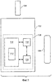
на фиг.1 представлена упрощенная блок-схема комплекта, предназначенного для определения аналита в образце жидкости организма в соответствии с примерным вариантом выполнения настоящего изобретения;figure 1 presents a simplified block diagram of a kit designed to determine the analyte in a sample of body fluid in accordance with an exemplary embodiment of the present invention;
на фиг.2 показан упрощенный вид спереди аналитического измерителя и аналитической индикаторной полоски, которые могут быть включены в комплекты в соответствии с вариантами выполнения настоящего изобретения;figure 2 shows a simplified front view of the analytical meter and analytical indicator strip, which can be included in sets in accordance with the variants of implementation of the present invention;
на фиг.3 показан упрощенный вид сбоку аналитического измерителя по фиг.2;figure 3 shows a simplified side view of the analytical meter of figure 2;
на фиг.4 показана упрощенная блок-схема последовательности операций, иллюстрирующая примерную конфигурацию управляемого по событиям, основанного на разделах отображения обучающих изображений, которая может использоваться в различных вариантах выполнения настоящего изобретения;4 is a simplified flowchart illustrating an exemplary configuration of an event-driven, based on display sections of training images that can be used in various embodiments of the present invention;
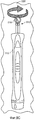
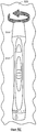
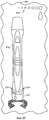
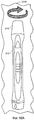
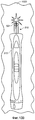
на фиг.5A-5G изображено упрощенное представление частей обучающих изображений раздела, предназначенного для обучения пользователя подготовке устройства для прокола и ланцета обучающей программы, которую можно использовать в вариантах выполнения настоящего изобретения;on figa-5G depicts a simplified representation of the parts of the training images of the section for teaching the user how to prepare a device for puncture and lancet training program, which can be used in embodiments of the present invention;
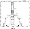
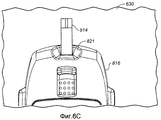
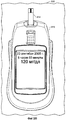
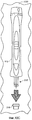
на фиг.6A-6F показано упрощенное представление частей обучающих изображений раздела, предназначенного для обучения пользователя установке индикаторной полоски, обучающей программы, которую можно использовать в вариантах выполнения настоящего изобретения;on figa-6F shows a simplified representation of the parts of the training images of the section for teaching the user how to install the indicator strip, a training program that can be used in embodiments of the present invention;
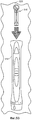
на фиг.7A и 7B показаны упрощенные изображения частей обучающих изображений раздела, предназначенного для обучения пользователя проколу пальца, обучающей программы, которая может использоваться в вариантах выполнения настоящего изобретения;on figa and 7B shows a simplified image of the parts of the training images of the section for teaching the user how to pierce the finger, a training program that can be used in embodiments of the present invention;
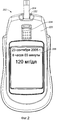
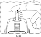
на фиг.8A-8C показано упрощенное изображение частей обучающих изображений раздела, предназначенного для обучения пользователя дозированию образца жидкости организма (то есть, образца цельной крови), обучающей программы, которая может использоваться в вариантах выполнения настоящего изобретения;on figa-8C shows a simplified image of the parts of the training images of the section designed to educate the user in the dosing of a sample of body fluid (that is, a sample of whole blood), a training program that can be used in embodiments of the present invention;
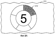
на фиг.9A и 9B показано упрощенное представление частей обучающих изображений раздела, предназначенного для обучения пользователя при имитации проверки, обучающей программы, которая может использоваться в вариантах выполнения настоящего изобретения;on figa and 9B shows a simplified representation of the parts of the training images of the section for teaching the user to simulate verification, a training program that can be used in embodiments of the present invention;
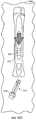
на фиг.10A-10E показаны упрощенные представления частей обучающих изображений раздела, предназначенного для обучения пользователя выбрасыванию использованного ланцета, обучающей программы, которая может использоваться в вариантах выполнения настоящего изобретения;10A-10E show simplified representations of portions of training images of a section for teaching a user to discard a used lancet, a training program that can be used in embodiments of the present invention;
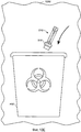
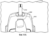
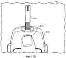
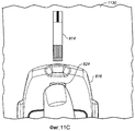
на фиг.11A-11C показаны упрощенные представления частей обучающих изображений раздела, предназначенного для обучения пользователя выбрасыванию использованной индикаторной полоски, обучающей программы, которая может использоваться в вариантах выполнения настоящего изобретения; и11A-11C show simplified representations of portions of training images of a section for teaching a user to throw away a used indicator strip, a training program that can be used in embodiments of the present invention; and
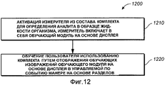
на фиг.12 показана блок-схема последовательности операций, описывающая этапы в процессе обучения пользователя использованию комплекта для определения аналита в образце жидкости организма в соответствии с примерным вариантом выполнения настоящего изобретения.12 is a flowchart describing steps in teaching a user to use a kit for determining analyte in a body fluid sample in accordance with an exemplary embodiment of the present invention.
Подробное описание изобретенияDETAILED DESCRIPTION OF THE INVENTION
На фиг.1 показана упрощенная блок-схема комплекта 100, предназначенного для определения аналита (такого как глюкоза) в образце жидкости организма (например, образце цельной крови) в соответствии с примерным вариантом выполнения настоящего изобретения. Комплект 100 включает в себя аналитический измеритель 102, аналитическую индикаторную полоску 104 и устройство 106 для прокола.Figure 1 shows a simplified block diagram of a kit 100 for determining an analyte (such as glucose) in a body fluid sample (e.g., a whole blood sample) in accordance with an exemplary embodiment of the present invention. Kit 100 includes an
Аналитическая индикаторная полоска 104 выполнена с возможностью нанесения на нее образца жидкости организма и установки ее в аналитический измеритель 102 для последующего определения аналита в образце жидкости организма. Аналитический измеритель 102 (также называемый просто "измерителем") имеет обучающий модуль 108 на основе дисплея (представлен внутри пунктирной линии на фиг.1), который включает в себя интерфейс 110 пользователя (с визуальным дисплеем 112), модуль 114 памяти и микропроцессорный модуль 116.
Модуль 114 памяти выполнен с возможностью хранения обучающей программы, причем эта сохраненная обучающая программа содержит множество разделов. Кроме того, каждый из множества разделов содержит, по меньшей мере, одно обучающее изображение, представляющее использование комплекта. Обучающие изображения могут быть сохранены и могут быть скомпонованы по разделам с использованием любой соответствующей технологии, известной специалистам в данной области техники, включая сохранение цифрового изображения с использованием аппаратных средств и методик компоновки, и/или сохранения с использованием программных средств и методик компоновки. Кроме того, модуль 114 памяти может представлять собой любой соответствующий модуль памяти, известный специалистам в данной области техники, включая, например, модули твердотельного энергонезависимого запоминающего устройства (ЭНЗУ, NVM) или запоминающее устройство на основе оптического диска.The
Микропроцессорный модуль 116 выполнен с возможностью управления, по меньшей мере, интерфейсом пользователя и модулем памяти и координирования их работы. Кроме того, интерфейс 110 пользователя, микропроцессорный модуль 116 и модуль 114 памяти функционально соединены и выполнены (как представлено двунаправленными стрелками на фиг.1) с возможностью обеспечения управляемого по событиям основывающегося на разделах отображения обучающих изображений для пользователя на визуальном дисплее 112.The
Отображаемые обучающие изображения могут иметь любую соответствующую форму, включая, например, изображения, которые представляют собой иллюстрацию, картинки, схемы и/или могут быть упрощенными или нет, и поэтому не обязательно должны точно отражать все механические или визуальные детали, и/или быть представлены в масштабе. Однако такие обучающие изображения выполнены достаточно точно и подробно для обеспечения требуемого назначения, а именно обучения пользователя использованию и работе комплекта или измерителя для определения аналита в образце жидкости организма.The displayed training images may have any appropriate shape, including, for example, images that are illustrations, pictures, diagrams and / or may be simplified or not, and therefore need not accurately reflect all mechanical or visual details, and / or be presented to scale. However, such training images are made accurately enough and in detail to ensure the desired purpose, namely, training the user to use and operate the kit or meter to determine the analyte in a body fluid sample.
Кроме того, такие обучающие изображения могут быть статичными или анимированными (например, анимированная последовательность обучающих изображений) и могут, если это требуется, включать в себя текст, связанный с изображением. Обучающие изображения представляют собой изображения, которые, например, иллюстрируют, как правильно требуется выполнять конкретную операцию при использовании комплекта для определения аналита в образце жидкости организма или аналитического измерителя для определения аналита в образце жидкости организма. Отображение таких обучающих изображений также предпочтительно может использоваться для подсказки или напоминания пользователю о том, что определенное действие должно быть рассмотрено и/или выполнено пользователем.In addition, such training images may be static or animated (for example, an animated sequence of training images) and may, if desired, include text associated with the image. Training images are images that, for example, illustrate how to perform a particular operation correctly when using the kit for determining the analyte in a body fluid sample or the analytical meter to determine the analyte in a body fluid sample. The display of such training images can also preferably be used to prompt or remind the user that a specific action should be reviewed and / or performed by the user.
После ознакомления с настоящим описанием для специалиста в данной области техники будет понятно, что любое соответствующее средство может использоваться для конфигурирования интерфейса пользователя, микропроцессорного модуля и модуля памяти так, что они будут функционировать, как описано выше, включая соответствующее использование электронных схем, датчиков, программных средств и механических устройств, как известно в данной области техники.After reviewing the present description, it will be understood by a person skilled in the art that any appropriate means can be used to configure the user interface, microprocessor module and memory module so that they will function as described above, including the appropriate use of electronic circuits, sensors, software means and mechanical devices, as is known in the art.
В аналитическом измерителе 102 может использоваться любая соответствующая аналитическая методика или методики для определения аналита в образце жидкости организма, включая, например, методики, используемые в коммерчески доступных измерителях. Такие методики включают в себя, но не ограничиваются этим, методики, работающие на основе фотометрического и электрохимического принципа. После ознакомления с настоящим описанием для специалиста в данной области техники будут понятны различные способы, с помощью которых обычные измерители могут быть адаптированы для воплощения варианта выполнения настоящего изобретения. Например, микропроцессорный модуль, модуль памяти и интерфейс пользователя, как описано здесь, можно соответствующим образом интегрировать с обычным в остальном измерителем для воплощения варианта выполнения настоящего изобретения.
Интерфейс 110 пользователя обучающего модуля 108, работающего на основе дисплея, может представлять собой любой соответствующий интерфейс пользователя и может включать в себя, в дополнение к визуальному дисплею 112, кнопки, которыми оперирует пользователь (не показаны на фиг.1). Визуальный дисплей 112 может представлять собой, например, любой соответствующий экран отображения, известный специалистам в данной области техники, включая экран жидкокристаллического дисплея (ЖКД, LCD). Соответствующие экраны дисплея включают в себя, без ограничений, экраны дисплея, выполненные с возможностью отображения обучающих изображений в соответствии с настоящим изобретением, включая статические графические изображения (с соответствующим текстом и/или без текста) и анимированные графические изображения (с соответствующим текстом и/или без текста).The
На фиг.2 показан упрощенный вид спереди аналитического измерителя 202 и аналитической индикаторной полоски 204 (показана установленной в аналитический измеритель 202), которые могут быть включены в комплекты в соответствии с вариантами выполнения настоящего изобретения. На фиг.3 показан упрощенный вид сбоку аналитического измерителя 202.Figure 2 shows a simplified front view of the
Как показано на фиг.2 и 3, аналитический измеритель 202 включает в себя корпус 220 и соединитель 222 вместилища полоски, предназначенный для установки аналитической индикаторной полоски 204. Аналитический измеритель 202 также включает в себя кнопку 224 выталкивания аналитической индикаторной полоски и обучающий модуль на основе дисплея (показан не полностью), как описано выше со ссылкой на фиг.1. Обучающий модуль на основе дисплея из состава аналитического измерителя 202 включает в себя интерфейс пользователя с визуальным дисплеем 226 и кнопку 228 обучения, с которой работает пользователь. Другие элементы обучающего модуля на основе дисплея, такие как модуль памяти и микропроцессорный модуль, не видны на изображении в перспективе, показанном на фиг.2 и 3. Для специалистов в данной области техники будет понятно, что аналитический измеритель 202 также включает в себя соответствующие схемы и датчики, предназначенные для определения аналита в образце жидкости организма, который был помещен (также называется "дозирован") на аналитическую индикаторную полоску 204.As shown in FIGS. 2 and 3, the
Хотя визуальный дисплей 226 рассматривается как компонент обучающего модуля на основе дисплея из состава аналитического измерителя 202, визуальный дисплей 226 также можно использовать для выполнения других функций, связанных с работой аналитического измерителя 202. Например, визуальный дисплей 226 можно использовать для отображения даты, времени и значения концентрации глюкозы, как показано на фиг.2.Although the
Кнопка 228, с которой работает пользователь, выполнена таким образом, что нажатие на нее рассматривается как событие микропроцессорным модулем основанного на событии обучающего модуля на основе дисплея с целью отображения обучающих изображений в соответствии с управлением по событиям и на основе разделов. Как будет понятно из описания, приведенного ниже со ссылкой на фиг.4, событие представляется уникальным по его контексту, то есть в соответствии с другими событиями, которые предшествовали ему.The
Такие уникальные события и способ их интерпретации, например микропроцессорным модулем при управляемом по событиям основывающемся на разделах отображении обучающих изображений, более подробно описаны со ссылкой на фиг.4-11C. В случае необходимости кнопка 228 обучения, с которой работает пользователь, также быть может выполнена таким образом, что нажатие на нее приводит к последовательному представлению отображаемого обучающего изображения в пределах данного раздела обучающей программы. Следует также отметить, что дополнительные кнопки интерфейса пользователя, с которыми работает пользователь, могут быть включены в вариантах выполнения настоящего изобретения и могут быть выполнены с возможностью возврата к отображаемому ранее обучающему изображению в пределах данного раздела обучающей программы.Such unique events and the way they are interpreted, for example by a microprocessor module with event-driven partition-based display of training images, are described in more detail with reference to FIGS. 4-11C. If necessary, the
На фиг.4 показана упрощенная блок-схема последовательности операций, иллюстрирующая примерную конфигурацию 400 управляемого по событиям основывающегося на разделах отображения обучающих изображений, которая может использоваться в различных вариантах выполнения настоящего изобретения. В конфигурации 400 иллюстрируется управляемое по событиям основывающееся на разделах отображение обучающих изображений для обучающей программы, которая имеет семь разделов, причем каждый из разделов содержит, по меньшей мере, одно обучающее изображение, представляющее использование комплекта для определения аналита (то есть, глюкозы) в образце жидкости организма (то есть, в образце цельной крови). Для специалиста в данной области техники будет понятно, что такие разделы и организационная структура могут быть определены в модуле памяти, например, с использованием программных средств и/или путем сохранения обучающих изображений в определенных местах расположения в пределах модуля памяти, специально выделенных для заданного раздела.FIG. 4 is a simplified flowchart illustrating an example configuration 400 of an event-driven partition-based training image display that may be used in various embodiments of the present invention. Configuration 400 illustrates an event-driven section-based display of training images for a training program that has seven sections, each section containing at least one training image representing the use of a kit for determining analyte (i.e., glucose) in a sample body fluids (i.e., in a sample of whole blood). It will be understood by those skilled in the art that such sections and organizational structure can be defined in a memory module, for example, using software tools and / or by storing training images at specific locations within a memory module specially allocated for a given section.
На фиг.5А-5G показаны упрощенные представления частей семи обучающих изображений раздела, предназначенного для обучения пользователя подготовке устройства для прокола и ланцета, которые указаны в конфигурации 400 на этапе 406. На фиг.6A-6F показаны упрощенные представления частей обучающих изображений другого раздела, предназначенного для обучения пользователя установке индикаторной полоски в измеритель, которые указаны в конфигурации 400 на этапе 408. На фиг.7A и 7B показаны упрощенные представления частей обучающих изображений еще одного раздела, предназначенного для обучения пользователя проколу пальца, как указано в конфигурации 400 на этапе 410.FIGS. 5A-5G show simplified representations of parts of seven training images of a section for teaching a user to prepare a puncture and lancet device, which are specified in configuration 400 at step 406. FIGS. 6A-6F show simplified representations of parts of training images of another section, designed to train the user to install the indicator strip in the meter, which are indicated in the configuration 400 at step 408. FIGS. 7A and 7B show simplified representations of parts of training images of another section la, intended for training the user to puncture the finger, as stated in configuration 400 at step 410.
На фиг.8A-8C показаны упрощенные представления частей обучающих изображений еще одного раздела, предназначенного для обучения пользователя дозированию образца жидкости организма (например, образца цельной крови), как обозначено в конфигурации 400 на этапе 412. На фиг.9A и 9B показаны упрощенные представления частей обучающих изображений дополнительного раздела, предназначенного для обучения пользователя на основе имитации измерения, как обозначено в конфигурации 400 на этапе 414.FIGS. 8A-8C show simplified representations of portions of training images of another section for teaching a user to dose a body fluid sample (eg, a whole blood sample), as indicated in configuration 400 in step 412. FIGS. 9A and 9B show simplified representations. parts of the training images of an additional section designed to educate the user on the basis of simulation measurements, as indicated in the configuration 400 at step 414.
На фиг.10A-10E показано упрощенное представление частей обучающих изображений еще одного раздела, предназначенного для обучения пользователя выбрасыванию использованного ланцета, как обозначено в конфигурации 400 на этапе 418. На фиг.11A-11C показаны упрощенные представления частей обучающих изображений еще одного дополнительного раздела, предназначенного для обучения пользователя выбрасыванию использованной индикаторной полоски, как обозначено в конфигурации 400 на этапе 420.On figa-10E shows a simplified representation of the parts of the training images of another section, designed to teach the user how to throw a used lancet, as indicated in the configuration 400 at step 418. On figa-11C shows simplified representations of the parts of the training images of another additional section, intended to educate the user on how to throw away the used indicator strip, as indicated in configuration 400 in step 420.
Как указано выше, интерфейс пользователя, микропроцессорный модуль и модуль памяти обучающих программ на основе отображения, используемых в вариантах выполнения настоящего изобретения, функционально соединены и выполнены с возможностью управляемого по событиям основывающегося на разделах отображения обучающих изображений для пользователя на визуальном дисплее 112. В качестве примера, но без ограничений, управляемые по событиям основывающиеся на разделах отображения обучающих изображений, для которых может быть создана такая обучающая программа на основе отображения, указаны в конфигурации 400 на фиг.4.As indicated above, the user interface, the microprocessor module, and the display-based training program memory module used in the embodiments of the present invention are functionally coupled and configured to be event-driven partition-based display of training images for the user on the
Как показано на фиг.4 и на фиг.5A-11C, аналитический измеритель в соответствии с вариантами выполнения настоящего изобретения, который находится в "выключенном состоянии" (то есть, деактивирован, см. этап 402 в конфигурации 400) может быть включен пользователем с использованием различных средств, например, путем нажатия на кнопку обучения (например, кнопку обучения, которой оперирует пользователь, как описано выше со ссылкой на фиг.2 и 3), автоматически при установке аналитической индикаторной полоски (на фиг.4 называется просто "Полоской") или с использованием любого другого средства активации.As shown in FIGS. 4 and 5A-11C, an analyzer in accordance with embodiments of the present invention that is in an “off” state (i.e., deactivated, see step 402 in configuration 400) can be turned on by a user with using various means, for example, by pressing the training button (for example, the training button operated by the user, as described above with reference to FIGS. 2 and 3), automatically when the analytical indicator strip is installed (in FIG. 4 it is simply called the “Strip” ) or with isp lzovaniem any other means of activation.
После активации аналитического измерителя микропроцессорный модуль из состава управляемого по событиям обучающего модуля определяет уникальное событие, которое произошло, и затем, совместно с модулем памяти и визуальным дисплеем, отображает раздел обучающей программы, который ассоциирован с определенным уникальным событием. Например, если устройство было активировано путем нажатия на кнопку обучения, отображается заданное отображающее сообщение на визуальном дисплее (см. этап 404 в конфигурации 400). Такое открывающее сообщение может включать в себя, например, фирменный знак, текущую дату, текущее время и последнее измеренное значение концентрации глюкозы.After the analyzer is activated, the microprocessor module from the event-driven training module determines the unique event that occurred, and then, together with the memory module and the visual display, displays a section of the training program that is associated with a specific unique event. For example, if the device was activated by pressing the learning button, the specified display message is displayed on the visual display (see step 404 in configuration 400). Such an opening message may include, for example, a brand name, current date, current time, and last measured glucose concentration value.
Кроме того, в конфигурации по фиг.4 после второго нажатия на кнопку обучения в управляемом по событиям основывающемся на разделах отображении выполняется отображение учебных изображений, связанных с подготовкой ланцета (см. этап 406 конфигурации 400). Пример таких обучающих изображений представлен на фиг.5-5G, на которых:In addition, in the configuration of FIG. 4, after the second press of the learning button, in the event-driven partition-based display, training images associated with the preparation of the lancet are displayed (see step 406 of configuration 400). An example of such training images is presented in FIGS. 5-5G, in which:
на фиг.5A показана часть обучающего изображения 510, обозначающая этап подготовки устройства 512 для прокола, который включает в себя съем колпачка 514 устройства для прокола с выполнением движения по часовой стрелке (как обозначено стрелкой на фиг.5A);on figa shows part of the
на фиг.5B показана часть обучающего изображения 520, представляющего этап подготовки устройства 512 для прокола путем установки (в направлении стрелки, показанной на фиг.5B) ланцета 516 в устройство 512 для прокола со снятым колпачком 514 устройства для прокола;FIG. 5B shows a portion of the
на фиг.5C показана часть обучающего изображения 530, обозначающего этап подготовки устройства для прокола путем удаления колпачка 518 ланцета с использованием кругового движения (как обозначено стрелкой на фиг.5C);on figs shows part of the
на фиг.5D показана часть обучающего изображения 540, представляющего этап подготовки устройства для прокола, на котором выделен (с использованием изображения звездочки) острый кончик 521 ланцета, который открывается после удаления колпачка ланцета;on fig.5D shows a part of the
на фиг.5E показана часть обучающего изображения 550, представляющего этап подготовки устройства для прокола путем повторной установки колпачка с использованием движения по часовой стрелке (как обозначено стрелкой на фиг.5E);FIG. 5E shows a portion of the
на фиг.5F показана часть обучающего изображения 560, представляющего этап подготовки устройства для прокола путем регулирования механизма 522 управления глубиной устройства для прокола с помощью движения по часовой стрелке или движения против часовой стрелки с различными метками 524 управления глубиной, которые отдельно показаны в верхнем правом углу обучающего изображения 560; иFIG. 5F shows a portion of the
на фиг.5G показана часть обучающего изображения 570, обозначающего этап подготовки устройства для прокола, на котором пользователь взводит (то есть, переводит в состояние готовности) спусковой механизм 526 (как представлено стрелкой на фиг.5G).on figg shows a part of the
В качестве альтернативы, если активация обеспечивается при установке аналитической индикаторной полоски, для пользователя представляются управляемые по событиям основывающиеся на разделах отображения обучающих изображений, связанных с дозировкой крови, то есть нанесением образца цельной крови на аналитическую индикаторную полоску (см. этап 412 конфигурации 400). Пример таких обучающих изображений показан на фиг.8А-8C, на которых:Alternatively, if activation is provided by installing an analytical indicator strip, an event-driven based on display sections of training images related to blood dosage, i.e. applying a whole blood sample to the analytical indicator strip, is presented to the user (see step 412 of configuration 400). An example of such training images is shown in FIGS. 8A-8C, in which:
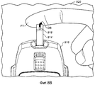
на фиг.8A показана часть обучающего изображения 810, представляющая этап дозирования образца крови, при этом показан кончик FT пальца, на котором имеется капелька DB крови рядом со входным отверстием 812 для образца аналитической индикаторной полоски 814, установленной в аналитический измеритель 816;on figa shows a portion of the
на фиг.8B показана часть обучающего изображения 820, представляющая этап дозирования образца крови, при этом представлено прикосновение капельки крови DB к входному отверстию 812 образца, в результате чего приемная камера 818 для образца аналитической индикаторной полоски 814 частично заполняется кровью; иFIG. 8B shows a portion of the
на фиг.8C показана часть обучающего изображения 830, представляющая этап, изображающий дозирование образца крови, при этом представлена камера 818 приема образца, полностью заполненная образцом BD крови.8C is a portion of the
Как показано на фиг.4, управляемое по событиям основывающееся на разделах отображение обучающих изображений, связанных с дозированием крови, то есть нанесением образца цельной крови на аналитическую индикаторную полоску (см. этап 412 в конфигурации 400), также может быть инициировано путем установки аналитической индикаторной полоски в аналитический измеритель в соответствии с любым из этапов 404, 406, 408 и 410 конфигурации 400. Кроме того, последовательность изображений, представленных на фиг.8A, 8B и 8C, если требуется, может отображаться в виде анимированной последовательности, которая отображает образец BD крови, впитывающийся в аналитическую индикаторную полоску 814.As shown in FIG. 4, an event-driven section-based display of training images related to blood dosing, that is, applying a whole blood sample to an analytical indicator strip (see step 412 in configuration 400), can also be triggered by setting an analytical indicator strips in the analytical meter in accordance with any of steps 404, 406, 408 and 410 of the configuration 400. In addition, the sequence of images shown in FIGS. 8A, 8B and 8C, if required, can be displayed as anim Rowan sequence that shows the blood sample BD soaking into the
Специалисту в данной области техники будет понятно, что обучающие изображения по фиг.5A-11C представляют собой примеры и что другие соответствующие обучающие изображения можно использовать в вариантах выполнения настоящего изобретения. Например, обучающее изображение, показанное внутри пунктирного прямоугольника на фиг.8A, само может использоваться как обучающее изображение, иллюстрирующее этап дозирования образца крови.One skilled in the art will understand that the training images of FIGS. 5A-11C are examples and that other appropriate training images can be used in embodiments of the present invention. For example, the training image shown inside the dashed rectangle in FIG. 8A can itself be used as a training image illustrating the step of dispensing a blood sample.
В другом управляемом по событиям основывающемся на разделах отображении обучающих изображений используется раздел обучающих изображений (таких как показаны на фиг.6A-6F), связанных с установкой полоски в аналитический измеритель (см. этап 408 на фиг.4). В варианте выполнения, показанном на фиг.4, таким отображением управляют на основе уникального события, состоящего в нажатии на кнопку обучения, после этапа 406. Примеры таких обучающих изображений показаны на фиг.6A-6F, на которых:Another event-driven partition-based display of training images uses a training images section (such as those shown in FIGS. 6A-6F) associated with installing a strip in the analyzer (see step 408 in FIG. 4). In the embodiment shown in FIG. 4, such a display is controlled based on the unique event of pressing the learning button after step 406. Examples of such training images are shown in FIGS. 6A-6F, in which:
на фиг.6A показана часть обучающего изображения 610, представляющего этап установки аналитической индикаторной полоски 814 в соединитель 821 вместилища полоски аналитического измерителя 816, на котором аналитическая индикаторная полоска находится за пределами соединителя 821 вместилища полоски аналитического измерителя 816;on figa shows part of the
на фиг.6B показана часть обучающего изображения 820, отображающая этап установки аналитической индикаторной полоски 814, на котором аналитическая индикаторная полоска 814 частично установлена в соединитель 820 вместилища полоски;FIG. 6B shows a portion of the
на фиг.6C показана часть обучающего изображения 830, представляющая этап установки аналитической индикаторной полоски 814, на котором аналитическая индикаторная полоска 814 полностью вставлена в соединитель 821 вместилища полоски;FIG. 6C shows a portion of the
на фиг.6D показана часть обучающего изображения 840, представляющая этап установки аналитической индикаторной полоски 814 в аналитический измеритель 816, которое предлагает пользователю удостовериться в том, что правильный калибровочный код CC индикаторной полоски (то есть, число "17", показанное внутри пунктирных кругов на фиг.6D) был введен в аналитический измеритель 816 путем отображения калибровочного кода на визуальном дисплее 822 аналитического измерителя 816 и на соответствующем пузырьке 900 с аналитическими индикаторными полосками;FIG. 6D shows a portion of the training image 840 representing the step of installing the
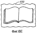
на фиг.6E показана часть обучающего изображения 650, которая предлагает пользователю обратиться к инструкции по эксплуатации во время установки аналитической индикаторной полоски, в случае когда возникает такая необходимость; и6E shows a portion of the
на фиг.6F показана часть обучающего изображения 660, которая предлагает пользователю удостовериться в правильности установки аналитической индикаторной полоски, представляя аналитический измеритель с соответствующим обучающим изображением на визуальном дисплее (то есть, изображение, показанное в пунктирном прямоугольнике на фиг.8A).FIG. 6F shows a portion of the
Если требуется, фиг.6A-6F могут отображаться на визуальном дисплее в виде последовательности анимированных изображений, представляющих установку аналитической индикаторной полоски 814 в соединитель 821 вместилища полоски. Кроме того, вместе с любыми обучающими изображениями может отображаться текст, связанный с изображением. Например, текст может отображаться в верхней области 660' обучающего изображения 660 и/или в верхней части 822' визуального дисплея 822 аналитического измерителя 816.If required, FIGS. 6A-6F may be displayed on the visual display as a series of animated images representing the installation of the
В следующем управляемом по событиям основывающемся на разделах отображении обучающих изображений используется раздел обучающих изображений (как показано на фиг.7A и 7B), относящийся к проколу пальца для получения образца цельной крови (см. этап 410 на фиг.4). В варианте выполнения, показанном на фиг.4 таким отображением управляют по уникальному событию, состоящему в нажатии на кнопку обучения, после этапа 408. Примеры таких обучающих изображений представлены на фиг.7A и 7B, на которых:The next event-driven partition-based display of the training images uses the training images section (as shown in FIGS. 7A and 7B) related to the puncture of a finger to obtain a whole blood sample (see step 410 in FIG. 4). In the embodiment shown in FIG. 4, such a display is controlled by a unique event consisting in pressing the learning button after step 408. Examples of such training images are shown in FIGS. 7A and 7B, in which:
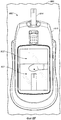
на фиг.7A показана часть обучающего изображения 710, отображающая этап прокола кончика FT пальца путем установки кончика FT пальца в верхней части устройства 512 для прокола; иFIG. 7A shows a portion of the
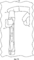
на фиг.7B показана часть обучающего изображения 720, отображающая этап прокола кончика FT пальца, который иллюстрируют активацию спускового механизма 526 большим пальцем UT пользователя.FIG. 7B shows a portion of the
В дополнительном управляемом по событиям основывающемся на разделах отображении обучающих изображений используется раздел обучающих изображений (таких, как показаны на фиг.9A и 9B), представляющий имитированное отображение теста с использованием аналитического измерителя (см. этап 414 конфигурации 400). В варианте выполнения по фиг.4 таким отображением управляют по уникальному событию, состоящему в нажатии на кнопку обучения, после этапа 412 (следует, однако, отметить, что, если на практике образец цельной крови дозируют после этапа 412, выполняются этапы 428 (отображение фактического обратного отсчета), 426 (отображение фактической концентрации глюкозы) и, в случае необходимости, 402' (выключение аналитического измерителя)). Примеры таких обучающих изображений показаны на фиг.9A и 9B, на которых:An additional event-driven partition-based display of training images uses a training images section (such as those shown in FIGS. 9A and 9B) representing a simulated test display using an analytical meter (see configuration step 414 of configuration 400). In the embodiment of FIG. 4, such a display is controlled by a unique event consisting in pressing the learning button after step 412 (it should be noted, however, that if in practice a whole blood sample is dosed after step 412, steps 428 are performed (display of the actual countdown), 426 (displaying the actual glucose concentration) and, if necessary, 402 '(turning off the analyzer). Examples of such training images are shown in FIGS. 9A and 9B, in which:
на фиг.9A показана часть обучающего изображения 910, представляющая отображение 912 обратного отсчета времени тестирования, в котором время тестирования представляет, что осталось пять секунд; иon figa shows a portion of the
на фиг.9B показана часть обучающего изображения 920, представляющая отображение концентрации глюкозы, определенной аналитическим измерителем.FIG. 9B shows a portion of a
Раздел изображений, примеры которых представлены на фиг.9A и 9B, представляет для пользователя обзор способа, в котором отображается обратный отсчет времени и концентрация глюкозы, без фактического дозирования образца цельной крови на аналитическую индикаторную полоску.The image section, examples of which are shown in FIGS. 9A and 9B, provides the user with an overview of the method in which the countdown and glucose concentration are displayed, without actually dosing the whole blood sample onto the analytical indicator strip.
Кроме того, в дополнительном, управляемом по событиям основывающемся на разделах отображении обучающих изображений используется раздел обучающих изображений (таких, как показаны на фиг.10A-10E), на которых представлено выбрасывание использованного ланцета (см. этап 418 конфигурации 400). В варианте выполнения по фиг.4 таким отображением управляют по уникальному событию, состоящему в нажатии на кнопку обучения после этапа 414, или уникальному событию нажатия на кнопку обучения после этапа 426 (следует, однако, отметить, что, если образец цельной крови будет дозирован после этапа 414, выполняются этапы 428 (отображение фактического обратного отсчета), 426 (отображение фактической концентрации глюкозы) и, в случае необходимости, 402' (выключение аналитического измерителя)). Примеры таких обучающих изображений показаны на фиг.10A-10E, на которых:In addition, an additional event-driven partition-based display of training images uses a training images section (such as those shown in FIGS. 10A-10E) that show the discard of the used lancet (see configuration step 418 of configuration 400). In the embodiment of FIG. 4, such a display is controlled by a unique event consisting in pressing the training button after step 414, or a unique event of pressing the training button after step 426 (it should be noted, however, that if the whole blood sample is dosed after of step 414, steps 428 (display of the actual countdown), 426 (display of the actual glucose concentration), and, if necessary, 402 '(shutdown of the analytical meter) are performed. Examples of such training images are shown in FIGS. 10A-10E, in which:
на фиг.10A показана часть обучающего изображения 1010, представляющая этап выбрасывания использованного ланцета путем съема вначале колпачка 514 устройства для прокола с поворотом его против часовой стрелки (как показано стрелкой на фиг.10A);on figa shows part of the
на фиг.10B показана часть обучающего изображения 1020, представляющая этап выбрасывания использованного ланцета, в котором колпачок 514 устройства для прокола был снят, в результате чего открылся острый кончик 521;10B is a portion of a
на фиг.10С показана часть обучающего изображения 1030, представляющая этап выбрасывания использованного ланцета, представляющая закрепление колпачка 518 ланцета на остром кончике 521;on figs shows part of the
на фиг.10D показана часть обучающего изображения 1040, представляющая этап выбрасывания использованного ланцета путем выталкивания использованного ланцета из устройства 512 для прокола; и10D shows a portion of the
на фиг.10E показана часть обучающего изображения 1050, представляющая этап выбрасывания использованного ланцета, путем иллюстрации использованного ланцета, выбрасываемого в контейнер HW для опасных отходов.10E is a portion of a
Также в управляемом по событиям основывающемся на разделах отображении обучающих изображений используется раздел обучающих изображений (таких, как показаны на фиг.11A-11C), которые отображают выбрасывание использованной аналитической индикаторной полоски (см. этап 420 конфигурации 400). В варианте выполнения по фиг.4 таким отображением управляют на основе события, состоящего в нажатии на кнопку обучения, после этапа 418 (следует, однако, отметить, что, если образец цельной крови был дозирован после этапа 418, выполняются этапы 428 (отображение фактического обратного отсчета), 426 (отображение фактической концентрации глюкозы) и, в случае необходимости, 402' (выключение аналитического измерителя)). Примеры таких обучающих изображений представлены на фиг.11A-11C, на которых:Also, an event-driven partition-based display of training images uses a training images section (such as those shown in FIGS. 11A-11C) that display the ejection of the used analytical indicator strip (see step 420 of configuration 400). In the embodiment of FIG. 4, such a display is controlled based on the event of pressing the learning button after step 418 (it should be noted, however, that if a whole blood sample was dosed after step 418, steps 428 are performed (displaying the actual reverse reference), 426 (display of the actual glucose concentration) and, if necessary, 402 '(switching off the analytical meter)). Examples of such training images are presented in figa-11C, on which:
на фиг.11A показана часть обучающего изображения 1110 на этапе выбрасывания использованной индикаторной полоски, выполняемого путем начала нажима на кнопку 824 выталкивания аналитического измерителя 816;on figa shows part of the
на фиг.11B показана часть обучающего изображения 1120 на этапе выбрасывания использованной индикаторной полоски с полным нажимом на кнопки 824 выталкивания; и11B shows a portion of the
на фиг.11C показана часть обучающего изображения 1130 на этапе выбрасывания использованной индикаторной полоски с иллюстрацией полностью вытолкнутой использованной аналитической индикаторной полоски.on figs shows part of the
Если образец цельной крови был дозирован после этапа 420, выполняются этапы 428 (отображение фактического обратного отсчета), 426 (отображение фактической концентрации глюкозы) и, в случае необходимости, 402' (дезактивация аналитического измерителя). После этапа 420 при нажатии на кнопку обучения аналитический измеритель определяет, выполняется ли фактический тест или имитация теста (см. этап 422 конфигурации 400). Если будет получен результат, представляющий имитацию теста, отображается сообщение об окончании работы (см. этап 424 конфигурации 400). Если будет определен фактический тест, тогда выполняются этапы 426 и 402' в соответствии с конфигурацией 400.If the whole blood sample was dosed after step 420, steps 428 (display of the actual countdown), 426 (display of the actual concentration of glucose) and, if necessary, 402 '(deactivation of the analyzer) are performed. After step 420, when the learning button is pressed, the analyzer determines whether the actual test or test simulation is being performed (see step 422 of configuration 400). If a result representing a test simulation is obtained, a completion message is displayed (see step 424 of configuration 400). If the actual test is determined, then steps 426 and 402 ′ are performed in accordance with the configuration 400.
Как описано выше, для каждого раздела обучающей программы в соответствии с настоящим изобретением назначается одно или больше уникальных событий, которые могут произойти во время использования комплекта или аналитического измерителя для определения аналита в образце жидкости организма. Уникальные события могут представлять собой, например, установку аналитической индикаторной полоски в аналитический измеритель после других заданных этапов или дозирования (то есть нанесения) образца жидкости организма на аналитическую индикаторную полоску после выполнения других заданных этапов. Кроме того, в случае когда пользователь не знает, что делать дальше в ходе определения аналита, пользователь может инициировать управляемое по событию основывающееся на разделах отображение обучающих изображений путем нажатия на кнопку обучения, которой оперирует пользователь. Поскольку обучающие изображения управляются по событию и основаны на разделах, они соответствуют вопросам, которые могут возникнуть у пользователя после каждого уникального события, которое происходит в ходе определения.As described above, for each section of the training program in accordance with the present invention, one or more unique events are assigned that can occur during the use of a kit or analytical meter to determine the analyte in a body fluid sample. Unique events can be, for example, the installation of an analytical indicator strip in an analytical meter after other specified steps or dosing (i.e. applying) a sample of body fluid to the analytical indicator strip after performing other specified steps. In addition, in the case when the user does not know what to do next during the determination of the analyte, the user can initiate an event-driven partition-based display of training images by pressing the training button operated by the user. Since training images are event-driven and section-based, they correspond to questions that the user may have after each unique event that occurs during the determination.
В соответствии с настоящим описанием для специалистов в данной области техники будет понятно, что другие события, кроме описанных выше, могут использоваться как основание для управляемого по событиям основывающегося на разделах отображения обучающих изображений. Например, события могут быть основаны на том, что аналитический измеритель распознает, что i) камера приема образца только частично заполнена кровью, ii) окружающая температура выше, чем приблизительно 45 градусов Цельсия, iii) окружающая температура ниже, чем приблизительно 4 градуса Цельсия, и iv) батарея аналитического измерителя почти полностью разряжена. Для каждого из этих событий могут быть составлены и назначены обучающие изображения в соответствии с разделом обучающей программы.In accordance with the present description, it will be understood by those skilled in the art that events other than those described above can be used as the basis for event-driven partition-based display of training images. For example, events may be based on the fact that the analyzer recognizes that i) the sample collection chamber is only partially filled with blood, ii) the ambient temperature is higher than about 45 degrees Celsius, iii) the ambient temperature is lower than about 4 degrees Celsius, and iv) The analyzer battery is almost empty. For each of these events, training images can be compiled and assigned in accordance with the tutorial section.
На фиг.12 показана блок-схема последовательности операций, отображающая этапы способа 1200, предназначенного для обучения пользователя использованию комплекта для определения аналита (такого как глюкоза) в образце жидкости организма (например, образце цельной крови) в соответствии с примерным вариантом выполнения настоящего изобретения. Способ 1200 включает в себя включение измерителя комплекта для определения аналита в образце жидкости организма, как обозначено на этапе 1210.12 is a flowchart showing steps of a
Измеритель, активированный на этапе 1210, включает в себя обучающий модуль на основе дисплея с интерфейсом пользователя (который имеет визуальный дисплей), модуль памяти и микропроцессорный модуль. Обучающая программа, которая содержит множество разделов, сохранена в модуле памяти. Кроме того, каждый из множества разделов содержит, по меньшей мере, одно обучающее изображение, представляющее использование комплекта. Микропроцессорный модуль выполнен с возможностью управления и координирования, по меньшей мере, интерфейса пользователя и модуля памяти. Кроме того, интерфейс пользователя, микропроцессорный модуль и модуль памяти функционально соединены и сконфигурированы для управляемого по событиям отображения на основе разделов обучающих изображений для пользователя визуального дисплея.The meter activated in
На этапе 1220 способа 1200 пользователя обучают использованию комплекта путем отображения обучающих изображений с управлением по событию на основе разделов на визуальном дисплее интерфейса пользователя.At
После ознакомления с настоящим описанием для специалистов в данной области техники будет понятно, что способы в соответствии с вариантами выполнения настоящего изобретения могут включать в себя этапы, которые осуществляют описанные здесь функциональные характеристики комплектов и аналитических измерителей в соответствии с вариантами выполнения настоящего изобретения. Например, этап активации способов в соответствии с настоящим изобретением может включать в себя активацию любого соответствующего измерителя, описанного в отношении вариантов выполнения настоящего изобретения.After reviewing the present description, it will be understood by those skilled in the art that methods in accordance with embodiments of the present invention may include steps that implement the functional characteristics of the kits and analytical meters described herein in accordance with embodiments of the present invention. For example, the step of activating methods in accordance with the present invention may include activating any appropriate meter described in relation to embodiments of the present invention.
Аналитические измерители, комплекты и способы в соответствии с настоящим изобретением являются предпочтительными, поскольку они предоставляют для пользователя обучающую программу в удобном для использования и визуальном формате (то есть, в управляемой по событиям конфигурации на основе разделов). Свойство управления по событиям устраняет для пользователя необходимость утомительной навигации через всю обучающую программу или инструкцию по эксплуатации, когда для пользователя требуется только конкретная часть обучающей программы (то есть, раздел). Поэтому свойство управления по событиям и на основе разделов аналитических измерителей, комплектов и способов в соответствии с настоящим изобретением обеспечивает рациональное средство отображения для пользователя только соответствующих обучающих изображений.Analytical meters, kits, and methods in accordance with the present invention are preferred because they provide the user with a training program in a user-friendly and visual format (i.e., in an event-driven configuration based on partitions). The event management property eliminates the need for the user to tedious navigation through the entire training program or operating instructions, when the user only needs a specific part of the training program (i.e., section). Therefore, the control property by events and based on sections of analytical meters, kits and methods in accordance with the present invention provides a rational means of displaying to the user only relevant training images.
Следует понимать, что различные альтернативы вариантам выполнения описанного здесь изобретения могут использоваться при воплощении на практике изобретения. Предполагается, что нижеследующая формула изобретения определяет объем изобретения и что этой формулой изобретения будут охвачены структуры и способы, находящиеся в пределах ее объема и объема ее эквивалентов.It should be understood that various alternatives to the embodiments of the invention described herein can be used in the practice of the invention. The following claims are intended to determine the scope of the invention and that structures and methods that are within its scope and the scope of its equivalents will be embraced by this claims.
Claims (10)
активируют аналитический измеритель из состава комплекта для определения аналита в образце жидкости организма, причем аналитический измеритель включает в себя:
модуль обучения на основе дисплея, включающий в себя:
интерфейс пользователя, который включает в себя визуальный дисплей;
модуль памяти, в котором хранится обучающая программа, причем обучающая программа имеет множество разделов, при этом каждый из этого множества разделов содержит, по меньшей мере, одно обучающее изображение, иллюстрирующее использование комплекта; и
микропроцессорный модуль, выполненный с возможностью управления, по меньшей мере, интерфейсом пользователя и модулем памяти и их координирования,
при этом интерфейс пользователя, микропроцессорный модуль и модуль памяти функционально соединены и сконфигурированы для управляемого по событию основывающегося на разделах отображения обучающих изображений для пользователя на визуальном дисплее, и
выполняют обучение пользователя использованию упомянутого комплекта путем отображения обучающих изображений на основе разделов в управляемой по событию манере.1. A method of teaching a user to use a kit for determining an analyte in a body fluid sample, comprising the steps of:
activate the analytical meter from the kit for determining the analyte in a sample of body fluid, and the analytical meter includes:
display-based learning module, including:
a user interface that includes a visual display;
a memory module in which the training program is stored, wherein the training program has many sections, each of these many sections containing at least one training image illustrating the use of the kit; and
a microprocessor module configured to control at least a user interface and a memory module and coordinate them,
wherein the user interface, the microprocessor module and the memory module are functionally connected and configured for event-driven display-based training images for the user on the visual display, and
the user is trained in using said kit by displaying training images based on sections in an event-driven manner.
при этом управляемое по событию основывающееся на разделах отображение обучающих изображений на этапе обучения включает в себя, по меньшей мере, одно управляемое по событию основывающееся на разделах отображение, инициируемое по событию, состоящему в том, что пользователь нажимает на кнопку обучения, которой оперирует пользователь.3. The method of claim 1, wherein the display-based learning module includes a learning button operated by a user,
wherein the event-driven section-based display of training images at the training stage includes at least one section-driven event-based display triggered by the event that the user clicks on the learning button operated by the user.
Applications Claiming Priority (4)
| Application Number | Priority Date | Filing Date | Title |
|---|---|---|---|
| US84258406P | 2006-09-05 | 2006-09-05 | |
| US60/842,584 | 2006-09-05 | ||
| US11/554,506 US20080057484A1 (en) | 2006-09-05 | 2006-10-30 | Event-driven method for tutoring a user in the determination of an analyte in a bodily fluid sample |
| US11/554,506 | 2006-10-30 |
Publications (2)
| Publication Number | Publication Date |
|---|---|
| RU2007133237A RU2007133237A (en) | 2009-03-10 |
| RU2530833C2 true RU2530833C2 (en) | 2014-10-20 |
Family
ID=39897927
Family Applications (2)
| Application Number | Title | Priority Date | Filing Date |
|---|---|---|---|
| RU2007133236/14A RU2471407C2 (en) | 2006-09-05 | 2007-09-04 | Analytical display-based meter with training module |
| RU2007133237/12A RU2530833C2 (en) | 2006-09-05 | 2007-09-04 | Event-controlled method of user training to detect analyte in body fluid sample |
Family Applications Before (1)
| Application Number | Title | Priority Date | Filing Date |
|---|---|---|---|
| RU2007133236/14A RU2471407C2 (en) | 2006-09-05 | 2007-09-04 | Analytical display-based meter with training module |
Country Status (11)
| Country | Link |
|---|---|
| US (2) | US20080057484A1 (en) |
| EP (2) | EP1897487B1 (en) |
| JP (2) | JP2008070361A (en) |
| CN (3) | CN101271058B (en) |
| AT (2) | ATE450196T1 (en) |
| BR (2) | BRPI0703444A (en) |
| CA (2) | CA2600167A1 (en) |
| DE (2) | DE602007003156D1 (en) |
| ES (2) | ES2336375T3 (en) |
| HK (2) | HK1115288A1 (en) |
| RU (2) | RU2471407C2 (en) |
Families Citing this family (165)
| Publication number | Priority date | Publication date | Assignee | Title |
|---|---|---|---|---|
| US6391005B1 (en) | 1998-03-30 | 2002-05-21 | Agilent Technologies, Inc. | Apparatus and method for penetration with shaft having a sensor for sensing penetration depth |
| US8641644B2 (en) | 2000-11-21 | 2014-02-04 | Sanofi-Aventis Deutschland Gmbh | Blood testing apparatus having a rotatable cartridge with multiple lancing elements and testing means |
| WO2002100460A2 (en) | 2001-06-12 | 2002-12-19 | Pelikan Technologies, Inc. | Electric lancet actuator |
| US9226699B2 (en) | 2002-04-19 | 2016-01-05 | Sanofi-Aventis Deutschland Gmbh | Body fluid sampling module with a continuous compression tissue interface surface |
| US7316700B2 (en) | 2001-06-12 | 2008-01-08 | Pelikan Technologies, Inc. | Self optimizing lancing device with adaptation means to temporal variations in cutaneous properties |
| AU2002348683A1 (en) | 2001-06-12 | 2002-12-23 | Pelikan Technologies, Inc. | Method and apparatus for lancet launching device integrated onto a blood-sampling cartridge |
| US9795747B2 (en) | 2010-06-02 | 2017-10-24 | Sanofi-Aventis Deutschland Gmbh | Methods and apparatus for lancet actuation |
| US7981056B2 (en) | 2002-04-19 | 2011-07-19 | Pelikan Technologies, Inc. | Methods and apparatus for lancet actuation |
| US9427532B2 (en) | 2001-06-12 | 2016-08-30 | Sanofi-Aventis Deutschland Gmbh | Tissue penetration device |
| US8337419B2 (en) | 2002-04-19 | 2012-12-25 | Sanofi-Aventis Deutschland Gmbh | Tissue penetration device |
| US7041068B2 (en) | 2001-06-12 | 2006-05-09 | Pelikan Technologies, Inc. | Sampling module device and method |
| US9248267B2 (en) | 2002-04-19 | 2016-02-02 | Sanofi-Aventis Deustchland Gmbh | Tissue penetration device |
| US8702624B2 (en) | 2006-09-29 | 2014-04-22 | Sanofi-Aventis Deutschland Gmbh | Analyte measurement device with a single shot actuator |
| US8221334B2 (en) | 2002-04-19 | 2012-07-17 | Sanofi-Aventis Deutschland Gmbh | Method and apparatus for penetrating tissue |
| US8579831B2 (en) | 2002-04-19 | 2013-11-12 | Sanofi-Aventis Deutschland Gmbh | Method and apparatus for penetrating tissue |
| US9314194B2 (en) | 2002-04-19 | 2016-04-19 | Sanofi-Aventis Deutschland Gmbh | Tissue penetration device |
| US7901362B2 (en) | 2002-04-19 | 2011-03-08 | Pelikan Technologies, Inc. | Method and apparatus for penetrating tissue |
| US7674232B2 (en) | 2002-04-19 | 2010-03-09 | Pelikan Technologies, Inc. | Method and apparatus for penetrating tissue |
| US8372016B2 (en) | 2002-04-19 | 2013-02-12 | Sanofi-Aventis Deutschland Gmbh | Method and apparatus for body fluid sampling and analyte sensing |
| US7232451B2 (en) | 2002-04-19 | 2007-06-19 | Pelikan Technologies, Inc. | Method and apparatus for penetrating tissue |
| US7229458B2 (en) | 2002-04-19 | 2007-06-12 | Pelikan Technologies, Inc. | Method and apparatus for penetrating tissue |
| US8267870B2 (en) | 2002-04-19 | 2012-09-18 | Sanofi-Aventis Deutschland Gmbh | Method and apparatus for body fluid sampling with hybrid actuation |
| US8360992B2 (en) | 2002-04-19 | 2013-01-29 | Sanofi-Aventis Deutschland Gmbh | Method and apparatus for penetrating tissue |
| US7708701B2 (en) | 2002-04-19 | 2010-05-04 | Pelikan Technologies, Inc. | Method and apparatus for a multi-use body fluid sampling device |
| US8784335B2 (en) | 2002-04-19 | 2014-07-22 | Sanofi-Aventis Deutschland Gmbh | Body fluid sampling device with a capacitive sensor |
| US7175642B2 (en) | 2002-04-19 | 2007-02-13 | Pelikan Technologies, Inc. | Methods and apparatus for lancet actuation |
| US7892183B2 (en) | 2002-04-19 | 2011-02-22 | Pelikan Technologies, Inc. | Method and apparatus for body fluid sampling and analyte sensing |
| US7491178B2 (en) | 2002-04-19 | 2009-02-17 | Pelikan Technologies, Inc. | Method and apparatus for penetrating tissue |
| US9795334B2 (en) | 2002-04-19 | 2017-10-24 | Sanofi-Aventis Deutschland Gmbh | Method and apparatus for penetrating tissue |
| US7909778B2 (en) | 2002-04-19 | 2011-03-22 | Pelikan Technologies, Inc. | Method and apparatus for penetrating tissue |
| US7547287B2 (en) | 2002-04-19 | 2009-06-16 | Pelikan Technologies, Inc. | Method and apparatus for penetrating tissue |
| US7331931B2 (en) | 2002-04-19 | 2008-02-19 | Pelikan Technologies, Inc. | Method and apparatus for penetrating tissue |
| US7297122B2 (en) | 2002-04-19 | 2007-11-20 | Pelikan Technologies, Inc. | Method and apparatus for penetrating tissue |
| US7976476B2 (en) | 2002-04-19 | 2011-07-12 | Pelikan Technologies, Inc. | Device and method for variable speed lancet |
| US8574895B2 (en) | 2002-12-30 | 2013-11-05 | Sanofi-Aventis Deutschland Gmbh | Method and apparatus using optical techniques to measure analyte levels |
| US7811231B2 (en) | 2002-12-31 | 2010-10-12 | Abbott Diabetes Care Inc. | Continuous glucose monitoring system and methods of use |
| US7587287B2 (en) | 2003-04-04 | 2009-09-08 | Abbott Diabetes Care Inc. | Method and system for transferring analyte test data |
| US7679407B2 (en) * | 2003-04-28 | 2010-03-16 | Abbott Diabetes Care Inc. | Method and apparatus for providing peak detection circuitry for data communication systems |
| ES2347248T3 (en) | 2003-05-30 | 2010-10-27 | Pelikan Technologies Inc. | PROCEDURE AND APPLIANCE FOR FLUID INJECTION. |
| US7850621B2 (en) | 2003-06-06 | 2010-12-14 | Pelikan Technologies, Inc. | Method and apparatus for body fluid sampling and analyte sensing |
| US8066639B2 (en) | 2003-06-10 | 2011-11-29 | Abbott Diabetes Care Inc. | Glucose measuring device for use in personal area network |
| WO2006001797A1 (en) | 2004-06-14 | 2006-01-05 | Pelikan Technologies, Inc. | Low pain penetrating |
| US7722536B2 (en) * | 2003-07-15 | 2010-05-25 | Abbott Diabetes Care Inc. | Glucose measuring device integrated into a holster for a personal area network device |
| WO2005033659A2 (en) | 2003-09-29 | 2005-04-14 | Pelikan Technologies, Inc. | Method and apparatus for an improved sample capture device |
| US9351680B2 (en) | 2003-10-14 | 2016-05-31 | Sanofi-Aventis Deutschland Gmbh | Method and apparatus for a variable user interface |
| US7822454B1 (en) | 2005-01-03 | 2010-10-26 | Pelikan Technologies, Inc. | Fluid sampling device with improved analyte detecting member configuration |
| US8668656B2 (en) | 2003-12-31 | 2014-03-11 | Sanofi-Aventis Deutschland Gmbh | Method and apparatus for improving fluidic flow and sample capture |
| WO2005089103A2 (en) | 2004-02-17 | 2005-09-29 | Therasense, Inc. | Method and system for providing data communication in continuous glucose monitoring and management system |
| US8828203B2 (en) | 2004-05-20 | 2014-09-09 | Sanofi-Aventis Deutschland Gmbh | Printable hydrogels for biosensors |
| US9775553B2 (en) | 2004-06-03 | 2017-10-03 | Sanofi-Aventis Deutschland Gmbh | Method and apparatus for a fluid sampling device |
| EP1765194A4 (en) | 2004-06-03 | 2010-09-29 | Pelikan Technologies Inc | Method and apparatus for a fluid sampling device |
| WO2005119524A2 (en) | 2004-06-04 | 2005-12-15 | Therasense, Inc. | Diabetes care host-client architecture and data management system |
| US9351669B2 (en) | 2009-09-30 | 2016-05-31 | Abbott Diabetes Care Inc. | Interconnect for on-body analyte monitoring device |
| US9636450B2 (en) | 2007-02-19 | 2017-05-02 | Udo Hoss | Pump system modular components for delivering medication and analyte sensing at seperate insertion sites |
| US7697967B2 (en) | 2005-12-28 | 2010-04-13 | Abbott Diabetes Care Inc. | Method and apparatus for providing analyte sensor insertion |
| US8029441B2 (en) | 2006-02-28 | 2011-10-04 | Abbott Diabetes Care Inc. | Analyte sensor transmitter unit configuration for a data monitoring and management system |
| US8652831B2 (en) | 2004-12-30 | 2014-02-18 | Sanofi-Aventis Deutschland Gmbh | Method and apparatus for analyte measurement test time |
| US7545272B2 (en) | 2005-02-08 | 2009-06-09 | Therasense, Inc. | RF tag on test strips, test strip vials and boxes |
| US7768408B2 (en) | 2005-05-17 | 2010-08-03 | Abbott Diabetes Care Inc. | Method and system for providing data management in data monitoring system |
| US8880138B2 (en) * | 2005-09-30 | 2014-11-04 | Abbott Diabetes Care Inc. | Device for channeling fluid and methods of use |
| US7756561B2 (en) * | 2005-09-30 | 2010-07-13 | Abbott Diabetes Care Inc. | Method and apparatus for providing rechargeable power in data monitoring and management systems |
| US7583190B2 (en) * | 2005-10-31 | 2009-09-01 | Abbott Diabetes Care Inc. | Method and apparatus for providing data communication in data monitoring and management systems |
| US7766829B2 (en) | 2005-11-04 | 2010-08-03 | Abbott Diabetes Care Inc. | Method and system for providing basal profile modification in analyte monitoring and management systems |
| US11298058B2 (en) | 2005-12-28 | 2022-04-12 | Abbott Diabetes Care Inc. | Method and apparatus for providing analyte sensor insertion |
| US7826879B2 (en) | 2006-02-28 | 2010-11-02 | Abbott Diabetes Care Inc. | Analyte sensors and methods of use |
| US7618369B2 (en) | 2006-10-02 | 2009-11-17 | Abbott Diabetes Care Inc. | Method and system for dynamically updating calibration parameters for an analyte sensor |
| US8473022B2 (en) | 2008-01-31 | 2013-06-25 | Abbott Diabetes Care Inc. | Analyte sensor with time lag compensation |
| US8140312B2 (en) | 2007-05-14 | 2012-03-20 | Abbott Diabetes Care Inc. | Method and system for determining analyte levels |
| US9392969B2 (en) | 2008-08-31 | 2016-07-19 | Abbott Diabetes Care Inc. | Closed loop control and signal attenuation detection |
| US8374668B1 (en) | 2007-10-23 | 2013-02-12 | Abbott Diabetes Care Inc. | Analyte sensor with lag compensation |
| US7653425B2 (en) | 2006-08-09 | 2010-01-26 | Abbott Diabetes Care Inc. | Method and system for providing calibration of an analyte sensor in an analyte monitoring system |
| US7620438B2 (en) | 2006-03-31 | 2009-11-17 | Abbott Diabetes Care Inc. | Method and system for powering an electronic device |
| US7801582B2 (en) | 2006-03-31 | 2010-09-21 | Abbott Diabetes Care Inc. | Analyte monitoring and management system and methods therefor |
| US20080124692A1 (en) * | 2006-10-26 | 2008-05-29 | Mcevoy Mary | Method for tutoring a user during use of a system for determining an analyte in a bodily fluid sample |
| US20080124693A1 (en) * | 2006-10-26 | 2008-05-29 | Mcevoy Mary | System for determining an analyte in a bodily fluid sample that includes a graphics-based step-by-step tutorial module |
| US8579853B2 (en) | 2006-10-31 | 2013-11-12 | Abbott Diabetes Care Inc. | Infusion devices and methods |
| US20080199894A1 (en) | 2007-02-15 | 2008-08-21 | Abbott Diabetes Care, Inc. | Device and method for automatic data acquisition and/or detection |
| US8123686B2 (en) | 2007-03-01 | 2012-02-28 | Abbott Diabetes Care Inc. | Method and apparatus for providing rolling data in communication systems |
| CA2683930A1 (en) | 2007-04-14 | 2008-10-23 | Abbott Diabetes Care Inc. | Method and apparatus for providing data processing and control in medical communication system |
| EP2146624B1 (en) | 2007-04-14 | 2020-03-25 | Abbott Diabetes Care Inc. | Method and apparatus for providing data processing and control in medical communication system |
| CA2683721C (en) | 2007-04-14 | 2017-05-23 | Abbott Diabetes Care Inc. | Method and apparatus for providing dynamic multi-stage signal amplification in a medical device |
| US10111608B2 (en) | 2007-04-14 | 2018-10-30 | Abbott Diabetes Care Inc. | Method and apparatus for providing data processing and control in medical communication system |
| US9204827B2 (en) | 2007-04-14 | 2015-12-08 | Abbott Diabetes Care Inc. | Method and apparatus for providing data processing and control in medical communication system |
| EP2146625B1 (en) | 2007-04-14 | 2019-08-14 | Abbott Diabetes Care Inc. | Method and apparatus for providing data processing and control in medical communication system |
| US8665091B2 (en) | 2007-05-08 | 2014-03-04 | Abbott Diabetes Care Inc. | Method and device for determining elapsed sensor life |
| US7928850B2 (en) | 2007-05-08 | 2011-04-19 | Abbott Diabetes Care Inc. | Analyte monitoring system and methods |
| US8461985B2 (en) | 2007-05-08 | 2013-06-11 | Abbott Diabetes Care Inc. | Analyte monitoring system and methods |
| US8456301B2 (en) | 2007-05-08 | 2013-06-04 | Abbott Diabetes Care Inc. | Analyte monitoring system and methods |
| US8260558B2 (en) | 2007-05-14 | 2012-09-04 | Abbott Diabetes Care Inc. | Method and apparatus for providing data processing and control in a medical communication system |
| US8444560B2 (en) | 2007-05-14 | 2013-05-21 | Abbott Diabetes Care Inc. | Method and apparatus for providing data processing and control in a medical communication system |
| US8600681B2 (en) | 2007-05-14 | 2013-12-03 | Abbott Diabetes Care Inc. | Method and apparatus for providing data processing and control in a medical communication system |
| US10002233B2 (en) | 2007-05-14 | 2018-06-19 | Abbott Diabetes Care Inc. | Method and apparatus for providing data processing and control in a medical communication system |
| US9125548B2 (en) | 2007-05-14 | 2015-09-08 | Abbott Diabetes Care Inc. | Method and apparatus for providing data processing and control in a medical communication system |
| US8103471B2 (en) | 2007-05-14 | 2012-01-24 | Abbott Diabetes Care Inc. | Method and apparatus for providing data processing and control in a medical communication system |
| US8560038B2 (en) | 2007-05-14 | 2013-10-15 | Abbott Diabetes Care Inc. | Method and apparatus for providing data processing and control in a medical communication system |
| US8239166B2 (en) | 2007-05-14 | 2012-08-07 | Abbott Diabetes Care Inc. | Method and apparatus for providing data processing and control in a medical communication system |
| AU2008265542B2 (en) | 2007-06-21 | 2014-07-24 | Abbott Diabetes Care Inc. | Health monitor |
| EP3533387A3 (en) | 2007-06-21 | 2019-11-13 | Abbott Diabetes Care, Inc. | Health management devices and methods |
| US8834366B2 (en) | 2007-07-31 | 2014-09-16 | Abbott Diabetes Care Inc. | Method and apparatus for providing analyte sensor calibration |
| US8377031B2 (en) | 2007-10-23 | 2013-02-19 | Abbott Diabetes Care Inc. | Closed loop control system with safety parameters and methods |
| US8409093B2 (en) | 2007-10-23 | 2013-04-02 | Abbott Diabetes Care Inc. | Assessing measures of glycemic variability |
| EP2400414B1 (en) | 2007-12-10 | 2022-03-02 | Ascensia Diabetes Care Holdings AG | Interface for a health measurement and monitoring system |
| US20090164239A1 (en) | 2007-12-19 | 2009-06-25 | Abbott Diabetes Care, Inc. | Dynamic Display Of Glucose Information |
| US9386944B2 (en) | 2008-04-11 | 2016-07-12 | Sanofi-Aventis Deutschland Gmbh | Method and apparatus for analyte detecting device |
| US7826382B2 (en) | 2008-05-30 | 2010-11-02 | Abbott Diabetes Care Inc. | Close proximity communication device and methods |
| US20100004522A1 (en) * | 2008-07-02 | 2010-01-07 | Eddie Varela | Continuously Wearable Compact Blood Glucose Measuring Device |
| WO2010009172A1 (en) | 2008-07-14 | 2010-01-21 | Abbott Diabetes Care Inc. | Closed loop control system interface and methods |
| US8734422B2 (en) | 2008-08-31 | 2014-05-27 | Abbott Diabetes Care Inc. | Closed loop control with improved alarm functions |
| US20100057040A1 (en) | 2008-08-31 | 2010-03-04 | Abbott Diabetes Care, Inc. | Robust Closed Loop Control And Methods |
| US9943644B2 (en) | 2008-08-31 | 2018-04-17 | Abbott Diabetes Care Inc. | Closed loop control with reference measurement and methods thereof |
| US8622988B2 (en) * | 2008-08-31 | 2014-01-07 | Abbott Diabetes Care Inc. | Variable rate closed loop control and methods |
| US8986208B2 (en) * | 2008-09-30 | 2015-03-24 | Abbott Diabetes Care Inc. | Analyte sensor sensitivity attenuation mitigation |
| US9375169B2 (en) | 2009-01-30 | 2016-06-28 | Sanofi-Aventis Deutschland Gmbh | Cam drive for managing disposable penetrating member actions with a single motor and motor and control system |
| US20100198034A1 (en) | 2009-02-03 | 2010-08-05 | Abbott Diabetes Care Inc. | Compact On-Body Physiological Monitoring Devices and Methods Thereof |
| WO2010127050A1 (en) | 2009-04-28 | 2010-11-04 | Abbott Diabetes Care Inc. | Error detection in critical repeating data in a wireless sensor system |
| WO2010138856A1 (en) | 2009-05-29 | 2010-12-02 | Abbott Diabetes Care Inc. | Medical device antenna systems having external antenna configurations |
| DK3689237T3 (en) | 2009-07-23 | 2021-08-16 | Abbott Diabetes Care Inc | Method of preparation and system for continuous analyte measurement |
| US8798934B2 (en) | 2009-07-23 | 2014-08-05 | Abbott Diabetes Care Inc. | Real time management of data relating to physiological control of glucose levels |
| WO2011014851A1 (en) | 2009-07-31 | 2011-02-03 | Abbott Diabetes Care Inc. | Method and apparatus for providing analyte monitoring system calibration accuracy |
| EP3001194B1 (en) | 2009-08-31 | 2019-04-17 | Abbott Diabetes Care, Inc. | Medical devices and methods |
| US8993331B2 (en) | 2009-08-31 | 2015-03-31 | Abbott Diabetes Care Inc. | Analyte monitoring system and methods for managing power and noise |
| US9314195B2 (en) | 2009-08-31 | 2016-04-19 | Abbott Diabetes Care Inc. | Analyte signal processing device and methods |
| US8965476B2 (en) | 2010-04-16 | 2015-02-24 | Sanofi-Aventis Deutschland Gmbh | Tissue penetration device |
| US11213226B2 (en) | 2010-10-07 | 2022-01-04 | Abbott Diabetes Care Inc. | Analyte monitoring devices and methods |
| CN107019515B (en) | 2011-02-28 | 2021-02-26 | 雅培糖尿病护理公司 | Method of displaying sensor readings and analyte monitoring device and method of operating the same |
| US10136845B2 (en) | 2011-02-28 | 2018-11-27 | Abbott Diabetes Care Inc. | Devices, systems, and methods associated with analyte monitoring devices and devices incorporating the same |
| KR101182730B1 (en) * | 2011-04-13 | 2012-09-13 | 주식회사 필로시스 | Apparatus for analyzing diagnosis strip having roller-typed ejector |
| US9317653B2 (en) * | 2011-07-22 | 2016-04-19 | Sysmex Corporation | Analyzer, and method for performing a measurement on a sample |
| US10514385B2 (en) | 2011-07-22 | 2019-12-24 | Sysmex Corporation | Hematology analyzer, method, and system for quality control measurements |
| US9297819B2 (en) * | 2011-07-22 | 2016-03-29 | Sysmex Corporation | Hematology analyzing system and analyzer |
| CN103076441B (en) * | 2011-10-25 | 2015-08-19 | 华广生技股份有限公司 | The biological sensing measuring system that test piece information can two-wayly be checked |
| US9069536B2 (en) | 2011-10-31 | 2015-06-30 | Abbott Diabetes Care Inc. | Electronic devices having integrated reset systems and methods thereof |
| US8710993B2 (en) | 2011-11-23 | 2014-04-29 | Abbott Diabetes Care Inc. | Mitigating single point failure of devices in an analyte monitoring system and methods thereof |
| US9317656B2 (en) | 2011-11-23 | 2016-04-19 | Abbott Diabetes Care Inc. | Compatibility mechanisms for devices in a continuous analyte monitoring system and methods thereof |
| US20130143246A1 (en) * | 2011-12-02 | 2013-06-06 | Lifescan Scotland Ltd. | Hand-held test meter with analytical test strip ejection mechanism |
| WO2013099239A1 (en) * | 2011-12-26 | 2013-07-04 | パナソニック株式会社 | Liquid sample measurement device |
| EP3395252A1 (en) | 2012-08-30 | 2018-10-31 | Abbott Diabetes Care, Inc. | Dropout detection in continuous analyte monitoring data during data excursions |
| US9968306B2 (en) | 2012-09-17 | 2018-05-15 | Abbott Diabetes Care Inc. | Methods and apparatuses for providing adverse condition notification with enhanced wireless communication range in analyte monitoring systems |
| AU2015312215B2 (en) | 2014-09-02 | 2017-10-19 | Apple Inc. | Physical activity and workout monitor |
| KR101621050B1 (en) * | 2014-10-23 | 2016-05-13 | 주식회사 이뮨메드 | Fluorescence reader of medical diagnostic kits |
| CN108024765B (en) | 2015-07-10 | 2021-06-11 | 雅培糖尿病护理公司 | System, device and method for dynamic glucose curve response to physiological parameters |
| CN107921317B (en) | 2015-08-20 | 2021-07-06 | 苹果公司 | Motion-based dial and complex function block |
| AU2017100667A4 (en) | 2016-06-11 | 2017-07-06 | Apple Inc. | Activity and workout updates |
| US11216119B2 (en) | 2016-06-12 | 2022-01-04 | Apple Inc. | Displaying a predetermined view of an application |
| US10736543B2 (en) | 2016-09-22 | 2020-08-11 | Apple Inc. | Workout monitor interface |
| JP7004333B2 (en) * | 2017-02-06 | 2022-01-21 | イーエフエー―エンジニアリング フォー オール エルティーディー. | Portable digital diagnostic device |
| WO2018175489A1 (en) | 2017-03-21 | 2018-09-27 | Abbott Diabetes Care Inc. | Methods, devices and system for providing diabetic condition diagnosis and therapy |
| US10845955B2 (en) | 2017-05-15 | 2020-11-24 | Apple Inc. | Displaying a scrollable list of affordances associated with physical activities |
| DK179980B1 (en) | 2018-03-12 | 2019-11-27 | Apple Inc. | User interfaces for health monitoring |
| US11317833B2 (en) | 2018-05-07 | 2022-05-03 | Apple Inc. | Displaying user interfaces associated with physical activities |
| DK179992B1 (en) | 2018-05-07 | 2020-01-14 | Apple Inc. | Visning af brugergrænseflader associeret med fysiske aktiviteter |
| US10953307B2 (en) | 2018-09-28 | 2021-03-23 | Apple Inc. | Swim tracking and notifications for wearable devices |
| DK201970532A1 (en) | 2019-05-06 | 2021-05-03 | Apple Inc | Activity trends and workouts |
| US11152100B2 (en) | 2019-06-01 | 2021-10-19 | Apple Inc. | Health application user interfaces |
| US11209957B2 (en) | 2019-06-01 | 2021-12-28 | Apple Inc. | User interfaces for cycle tracking |
| JP7297940B2 (en) | 2019-06-01 | 2023-06-26 | アップル インコーポレイテッド | Multimodal activity tracking user interface |
| US11234077B2 (en) | 2019-06-01 | 2022-01-25 | Apple Inc. | User interfaces for managing audio exposure |
| US11228835B2 (en) | 2019-06-01 | 2022-01-18 | Apple Inc. | User interfaces for managing audio exposure |
| DK201970534A1 (en) | 2019-06-01 | 2021-02-16 | Apple Inc | User interfaces for monitoring noise exposure levels |
| CN114706505A (en) | 2019-09-09 | 2022-07-05 | 苹果公司 | Research user interface |
| DK202070616A1 (en) | 2020-02-14 | 2022-01-14 | Apple Inc | User interfaces for workout content |
| DK181037B1 (en) | 2020-06-02 | 2022-10-10 | Apple Inc | User interfaces for health applications |
| US11698710B2 (en) | 2020-08-31 | 2023-07-11 | Apple Inc. | User interfaces for logging user activities |
| EP4323992A1 (en) | 2021-05-15 | 2024-02-21 | Apple Inc. | User interfaces for group workouts |
| US11896871B2 (en) | 2022-06-05 | 2024-02-13 | Apple Inc. | User interfaces for physical activity information |
Citations (1)
| Publication number | Priority date | Publication date | Assignee | Title |
|---|---|---|---|---|
| US20060053372A1 (en) * | 2004-09-08 | 2006-03-09 | Transcensus, Llc | Systems and methods for teaching a person to interact with a computer program having a graphical user interface |
Family Cites Families (27)
| Publication number | Priority date | Publication date | Assignee | Title |
|---|---|---|---|---|
| JPS58169289A (en) * | 1982-03-31 | 1983-10-05 | Fujitsu Ltd | Guidance system |
| ATE97791T1 (en) * | 1988-10-31 | 1993-12-15 | Avl Medical Instr Ag | DEVICE FOR DETERMINING THE CONCENTRATION OF AT LEAST ONE SUBSTANCE PRESENT IN ORGANIC TISSUE. |
| US7624028B1 (en) * | 1992-11-17 | 2009-11-24 | Health Hero Network, Inc. | Remote health monitoring and maintenance system |
| JP3046508B2 (en) * | 1994-10-27 | 2000-05-29 | シャープ株式会社 | Operation guidance display device for image forming apparatus |
| US5653918A (en) * | 1996-01-11 | 1997-08-05 | E. I. Du Pont De Nemours And Company | Flexible thick film conductor composition |
| JP2000005055A (en) * | 1998-06-22 | 2000-01-11 | Kubota Corp | Display device for automatic rice cooker |
| JP3214561B2 (en) * | 1998-07-02 | 2001-10-02 | 日本電気株式会社 | Enzyme electrode, biosensor and measuring device using the same |
| JP3668382B2 (en) * | 1998-11-19 | 2005-07-06 | テルモ株式会社 | Component measuring device |
| JP3540963B2 (en) * | 1999-07-01 | 2004-07-07 | シャープ株式会社 | Information display device |
| US20020068857A1 (en) * | 2000-02-14 | 2002-06-06 | Iliff Edwin C. | Automated diagnostic system and method including reuse of diagnostic objects |
| US6535714B2 (en) * | 2000-06-30 | 2003-03-18 | University Of Florida | Method, system, and apparatus for medical device training |
| CA2317825C (en) * | 2000-09-07 | 2006-02-07 | Ibm Canada Limited-Ibm Canada Limitee | Interactive tutorial |
| JP2002281186A (en) * | 2001-03-15 | 2002-09-27 | Canon Inc | User interface |
| US20030021729A1 (en) * | 2001-07-26 | 2003-01-30 | Bayer Corporation | Removable cover for a glucose meter |
| GB2388898B (en) * | 2002-04-02 | 2005-10-05 | Inverness Medical Ltd | Integrated sample testing meter |
| JP2004013458A (en) * | 2002-06-06 | 2004-01-15 | Nikon Corp | Online manual display system and online manual display method |
| US7572237B2 (en) * | 2002-11-06 | 2009-08-11 | Abbott Diabetes Care Inc. | Automatic biological analyte testing meter with integrated lancing device and methods of use |
| US20040152065A1 (en) * | 2002-11-14 | 2004-08-05 | Magiccom | Diagnostic demonstration devices and methods |
| US7229288B2 (en) * | 2002-12-20 | 2007-06-12 | Medtronic Minimed, Inc. | Method, system, and program for using a virtual environment to provide information on using a product |
| US20050055243A1 (en) * | 2003-06-30 | 2005-03-10 | Dave Arndt | Method and apparatus for managing data received from a medical device |
| US7640540B2 (en) * | 2003-10-24 | 2009-12-29 | Microsoft Corporation | Mechanism for providing extended functionality to command line instructions |
| US8343074B2 (en) * | 2004-06-30 | 2013-01-01 | Lifescan Scotland Limited | Fluid handling devices |
| US9098826B2 (en) * | 2004-09-30 | 2015-08-04 | The Invention Science Fund I, Llc | Enhanced user assistance |
| ITBO20050002A1 (en) * | 2005-01-04 | 2006-07-05 | Giacomo Vespasiani | METHOD AND SYSTEM FOR INTERACTIVE MANAGEMENT OF DATA CONCERNING AN INSULIN THERAPY IN SELF-CONTROL FOR A DIABETIC PATIENT |
| US20080124692A1 (en) * | 2006-10-26 | 2008-05-29 | Mcevoy Mary | Method for tutoring a user during use of a system for determining an analyte in a bodily fluid sample |
| US20080124693A1 (en) * | 2006-10-26 | 2008-05-29 | Mcevoy Mary | System for determining an analyte in a bodily fluid sample that includes a graphics-based step-by-step tutorial module |
| US20100095229A1 (en) * | 2008-09-18 | 2010-04-15 | Abbott Diabetes Care, Inc. | Graphical user interface for glucose monitoring system |
-
2006
- 2006-10-30 US US11/554,506 patent/US20080057484A1/en not_active Abandoned
- 2006-10-30 US US11/554,414 patent/US20080058626A1/en not_active Abandoned
-
2007
- 2007-09-04 ES ES07253502T patent/ES2336375T3/en active Active
- 2007-09-04 CA CA002600167A patent/CA2600167A1/en not_active Abandoned
- 2007-09-04 CA CA002600166A patent/CA2600166A1/en not_active Abandoned
- 2007-09-04 JP JP2007228911A patent/JP2008070361A/en active Pending
- 2007-09-04 DE DE602007003156T patent/DE602007003156D1/en active Active
- 2007-09-04 EP EP07253500A patent/EP1897487B1/en not_active Revoked
- 2007-09-04 DE DE602007003532T patent/DE602007003532D1/en active Active
- 2007-09-04 JP JP2007228913A patent/JP5139755B2/en not_active Expired - Fee Related
- 2007-09-04 AT AT07253502T patent/ATE450196T1/en not_active IP Right Cessation
- 2007-09-04 RU RU2007133236/14A patent/RU2471407C2/en not_active IP Right Cessation
- 2007-09-04 EP EP07253502A patent/EP1897488B1/en not_active Revoked
- 2007-09-04 RU RU2007133237/12A patent/RU2530833C2/en not_active IP Right Cessation
- 2007-09-04 ES ES07253500T patent/ES2334847T3/en active Active
- 2007-09-04 AT AT07253500T patent/ATE447881T1/en not_active IP Right Cessation
- 2007-09-05 CN CN2007101821161A patent/CN101271058B/en not_active Expired - Fee Related
- 2007-09-05 BR BRPI0703444-0A patent/BRPI0703444A/en not_active Application Discontinuation
- 2007-09-05 BR BRPI0703520-9A patent/BRPI0703520A/en not_active Application Discontinuation
- 2007-09-05 CN CNA2007101821157A patent/CN101231283A/en active Pending
- 2007-09-05 CN CNA2007101526955A patent/CN101363793A/en active Pending
-
2008
- 2008-05-13 HK HK08105271.1A patent/HK1115288A1/en not_active IP Right Cessation
- 2008-05-19 HK HK08105516.6A patent/HK1116378A1/en not_active IP Right Cessation
Patent Citations (1)
| Publication number | Priority date | Publication date | Assignee | Title |
|---|---|---|---|---|
| US20060053372A1 (en) * | 2004-09-08 | 2006-03-09 | Transcensus, Llc | Systems and methods for teaching a person to interact with a computer program having a graphical user interface |
Non-Patent Citations (1)
| Title |
|---|
| Инструкция к глюкометру "Optium Xceed" фирмы "Abbot", опул.20.08.2006, с.33,35,47,49,60,61 [он-лайн] [ найдено 2011-07-06]. Найдено в Интернет:http://abbottdiabetescare.com.au/downloads/133-221_Xceed_User_Manual_G3b_Aus.pdf. * |
Also Published As
| Publication number | Publication date |
|---|---|
| RU2007133237A (en) | 2009-03-10 |
| HK1115288A1 (en) | 2008-11-28 |
| ATE447881T1 (en) | 2009-11-15 |
| US20080058626A1 (en) | 2008-03-06 |
| ES2334847T3 (en) | 2010-03-16 |
| JP2008111827A (en) | 2008-05-15 |
| EP1897488A1 (en) | 2008-03-12 |
| EP1897487B1 (en) | 2009-11-11 |
| US20080057484A1 (en) | 2008-03-06 |
| BRPI0703520A (en) | 2008-04-22 |
| CN101271058B (en) | 2011-06-08 |
| BRPI0703444A (en) | 2008-04-22 |
| DE602007003532D1 (en) | 2010-01-14 |
| ES2336375T3 (en) | 2010-04-12 |
| DE602007003156D1 (en) | 2009-12-24 |
| HK1116378A1 (en) | 2008-12-24 |
| EP1897488B1 (en) | 2009-12-02 |
| JP5139755B2 (en) | 2013-02-06 |
| RU2007133236A (en) | 2009-03-10 |
| JP2008070361A (en) | 2008-03-27 |
| CN101231283A (en) | 2008-07-30 |
| EP1897487A1 (en) | 2008-03-12 |
| ATE450196T1 (en) | 2009-12-15 |
| CA2600167A1 (en) | 2008-03-05 |
| CN101271058A (en) | 2008-09-24 |
| CA2600166A1 (en) | 2008-03-05 |
| CN101363793A (en) | 2009-02-11 |
| RU2471407C2 (en) | 2013-01-10 |
Similar Documents
| Publication | Publication Date | Title |
|---|---|---|
| RU2530833C2 (en) | Event-controlled method of user training to detect analyte in body fluid sample | |
| RU2442986C2 (en) | Set for determination of analyte within body fluid sample including measuring instrument with display-based tutoring module | |
| US7976467B2 (en) | Method of inputting data into analyte testing device | |
| JP6081917B2 (en) | Guided systematic inspection kit | |
| CN101563693A (en) | Monitoring device | |
| EP1915944A1 (en) | Method for tutoring a user during use of a system for determining an analyte in a bodily fluid sample | |
| EP1915945A1 (en) | System for determining an analyte in a bodily fluid sample that includes a graphic-based step-by-step tutorial module | |
| CA2608677A1 (en) | System for determining an analyte in a bodily fluid sample that includes a graphics-based step-by-step tutorial module |
Legal Events
| Date | Code | Title | Description |
|---|---|---|---|
| MM4A | The patent is invalid due to non-payment of fees |
Effective date: 20190905 |