RU2529599C2 - Draw-and-straighten plant for long metal articles such as bars, round-section parts or metal wire - Google Patents
Draw-and-straighten plant for long metal articles such as bars, round-section parts or metal wire Download PDFInfo
- Publication number
- RU2529599C2 RU2529599C2 RU2011118232/02A RU2011118232A RU2529599C2 RU 2529599 C2 RU2529599 C2 RU 2529599C2 RU 2011118232/02 A RU2011118232/02 A RU 2011118232/02A RU 2011118232 A RU2011118232 A RU 2011118232A RU 2529599 C2 RU2529599 C2 RU 2529599C2
- Authority
- RU
- Russia
- Prior art keywords
- rollers
- roller
- drive
- metal
- pulling
- Prior art date
Links
Images
Classifications
-
- B—PERFORMING OPERATIONS; TRANSPORTING
- B21—MECHANICAL METAL-WORKING WITHOUT ESSENTIALLY REMOVING MATERIAL; PUNCHING METAL
- B21F—WORKING OR PROCESSING OF METAL WIRE
- B21F23/00—Feeding wire in wire-working machines or apparatus
- B21F23/002—Feeding means specially adapted for handling various diameters of wire or rod
Abstract
Description
Область техники, к которой относится изобретениеFIELD OF THE INVENTION
Настоящее изобретение относится к тянуще-правильной установке, которая может быть применена для подачи в обрабатывающий станок удлиненных (длинномерных) металлических изделий, таких как прутки, детали круглого сечения или металлическая проволока. В частности, тянуще-правильная установка в соответствии с настоящим изобретением предпочтительно применима в станках, обрабатывающих одновременно по меньшей мере два прутка, две круглые заготовки или две металлические проволоки за один прием, где указанная установка осуществляет одновременную подачу вышеупомянутых заготовок по существу равномерным и координированным образом, при этом указанная установка применима и для иных задач.The present invention relates to a pull-correct installation, which can be used to feed into the processing machine elongated (long) metal products, such as rods, parts of circular cross section or metal wire. In particular, the pulling-correct installation in accordance with the present invention is preferably applicable to machines that process at least two rods, two round billets or two metal wires simultaneously in one go, where the said machine simultaneously feeds the aforementioned billets in a substantially uniform and coordinated manner , while the specified installation is applicable for other tasks.
Уровень техникиState of the art
Известны гибочные/формовочные станки, также называемые станками для гибки арматуры, в которые подаются длинномерные металлические изделия, такие как металлическая проволока с катушки, стальные заготовки круглого сечения, предварительно нарезанные заготовки из металлической проволоки или прутка, с целью изготовления арматурных хомутов для строительства.Bending / forming machines are also known, also called reinforcement bending machines, in which long metal products are fed, such as metal wire from a coil, steel billets of circular cross-section, pre-cut billets from metal wire or bar, for the purpose of manufacturing reinforcing clamps for construction.
Обычно в станки производится подача двух или более металлоизделий одновременно с целью оптимизации производительности станка.Typically, two or more metal products are fed into machines simultaneously to optimize machine performance.
И металлоизделия, подаваемые с катушки, и предварительно нарезанные прутки, как правило, получают в результате горячей прокатки, и снаружи указанные металлические изделия содержат множество выступов рифления для улучшения условий сцепления с бетоном в процессе их применения.Both the metal products supplied from the coil and the pre-cut rods are usually obtained as a result of hot rolling, and from the outside, these metal products contain many corrugation protrusions to improve the adhesion conditions to concrete during their application.
Поскольку указанные металлоизделия изготовляют прокаткой, а также из-за наличия рифления сечение таких металлоизделий не является идеально круговым. Их сечение овальное и характеризуется большой осью, соответствующей выступам рифления, и малой осью, которая ступенчато сдвинута на 90° относительно большой оси и меньше большой оси на несколько миллиметров.Since these metal products are manufactured by rolling, and also due to the presence of corrugation, the cross section of such metal products is not perfectly circular. Their cross section is oval and is characterized by a large axis corresponding to corrugation protrusions, and a small axis, which is stepwise shifted 90 ° relative to the major axis and is several millimeters smaller than the major axis.
Известно также, что обрабатывающие станки, как правило, на входе, содержат тянуще-правильное устройство, предназначенное для подачи металлоизделий (заготовок) к рабочим органам станка.It is also known that processing machines, as a rule, at the entrance, contain a pulling-correct device designed to supply metal products (workpieces) to the working bodies of the machine.
Известны тянуще-правильные установки, которые состоят из множества роликов, расположенных с противоположных сторон оси подачи заготовок, для подачи последних в станок и/или их растягивания.Known pull-correct settings, which consist of many rollers located on opposite sides of the feed axis of the workpieces, for feeding the latter into the machine and / or stretching them.
Известные тянуще-правильные установки обычно содержат приводной ролик, оснащенный одним или более круговыми ручьями, в которых размещаются подаваемые металлические изделия, и один или более встречных роликов, которые расположены с противоположной стороны металлических изделий относительно приводного ролика.Known pull-correct installations typically comprise a drive roller equipped with one or more circular streams in which metal products to be fed are located, and one or more counter rollers that are located on the opposite side of the metal products relative to the drive roller.
Встречные ролики не связаны друг с другом, при этом каждый из них создает определенное усилие в направлении проводного ролика и соответствующего кругового ручья.Counter rollers are not connected to each other, while each of them creates a certain force in the direction of the wire roller and the corresponding circular stream.
Встречное усилие создается с целью обеспечения между металлической заготовкой и приводным роликом достаточного трения, ограничивающего возможность проскальзывания заготовки относительно ручья.Counter force is created in order to ensure sufficient friction between the metal workpiece and the drive roller, which limits the possibility of the workpiece slipping relative to the stream.
Известно также, что встречные ролики можно выборочно придвигать к приводному ролику в зависимости от диаметра обрабатываемой металлической заготовки.It is also known that counter rollers can be selectively pushed to the drive roller depending on the diameter of the metal workpiece being machined.
Кроме того, известно, что встречные ролики обычно демпфируют при помощи соответствующих упругих элементов, например тарельчатых пружин, которые предварительно загружены для поглощения вибраций или для компенсации (при приложении усилия) небольших вариаций диаметра металлических заготовок во время их движения.In addition, it is known that counter rollers are usually damped using appropriate elastic elements, for example, Belleville springs, which are preloaded to absorb vibrations or to compensate (with the application of force) small variations in the diameter of the metal workpieces during their movement.
Величину сближения встречных роликов с приводным роликом, а также предварительную загрузку упругих элементов определяют заранее и заранее выставляют, прежде чем начинать операцию подачи металлических заготовок в зависимости от их размера и типа.The proximity of the oncoming rollers with the drive roller, as well as the preloading of the elastic elements, are determined in advance and set in advance before starting the operation of feeding metal blanks depending on their size and type.
Обычно в процессе подачи известных металлических заготовок, в частности при подаче заготовок с катушки или в иных случаях, указанные металлические заготовки проявляют тенденцию к вращению, изменяя, таким образом, в процессе подачи угловое положение относительно собственной продольной оси.Usually in the process of supplying known metal preforms, in particular when feeding preforms from a coil or in other cases, these metal preforms tend to rotate, thus changing the angular position relative to their own longitudinal axis during the supply process.
Такие вариации углового положения могут приводить к предельным состояниям, при которых одна заготовка ориентирована так, что ее большая ось направлена по линии, соединяющей приводной ролик с соответствующим встречным роликом, в то время как другая заготовка оказывается ориентированной так, что ее малая ось направлена по линии, соединяющей приводной ролик с соответствующим встречным роликом.Such variations in the angular position can lead to limit states in which one workpiece is oriented so that its major axis is directed along the line connecting the drive roller to the corresponding counter roller, while the other workpiece is oriented so that its small axis is directed along the line connecting the drive roller to the corresponding counter roller.
Чтобы гарантировать протяжку заготовок даже при указанных предельных состояниях, сближение роликов и предварительный натяг упругих элементов выставляют эмпирически на некотором промежуточном уровне, который предположительно должен быть эффективным для обоих предельных состояний углового положения металлических заготовок.In order to guarantee broaching of the workpieces even at the indicated limit states, the approach of the rollers and the preload of the elastic elements are set empirically at a certain intermediate level, which is supposed to be effective for both limit states of the angular position of the metal workpieces.
Однако на практике заготовка, ориентированная между роликами малой осью, подвержена недостаточному поджатию и частично проскальзывает относительно ручья, в то время как для заготовок, ориентированных между роликами большой осью, поджатие оказывается чрезмерным.However, in practice, a workpiece oriented between the rollers with a small axis is subject to insufficient preload and partially slides relative to the stream, while for workpieces oriented between the rollers with a major axis, the preload is excessive.
Различие поджимающих воздействий встречных роликов на индивидуальные металлические заготовки приводит к различию скоростей подачи заготовок и к относительному проскальзыванию при подаче. Как следствие, возникает ошибка подачи заготовок к рабочим органам станка и опасность образования петель и растяжения металлических заготовок.The difference in the pressing effects of the counter rollers on the individual metal billets leads to a difference in the feed rates of the billets and to relative slippage during feeding. As a result, an error occurs in the supply of billets to the working bodies of the machine and the danger of loops and stretching of metal billets.
Действительно, в существующих технических решениях часто есть риск формования арматурных хомутов разного размера, которые не соответствуют техническим условиям.Indeed, in existing technical solutions there is often a risk of forming reinforcing clamps of different sizes that do not meet the technical conditions.
Кроме того, чрезмерное поджатие одной из металлических заготовок приводит к увеличенному износу ручьев приводного ролика, которые со временем теряют эффективность направляющего действия для надлежащей подачи заготовок.In addition, excessive preloading of one of the metal billets leads to increased wear of the drive roller streams, which over time lose the effectiveness of the guiding action for proper feeding of the billets.
Раскрытие изобретенияDisclosure of invention
Задачей настоящего изобретения является создание тянуще-правильной установки, которая позволяет простым и эффективным образом устранить недостатки, свойственные существующим техническим решениям, и дает возможность осуществлять одновременную и координированную подачу нескольких металлических изделий (заготовок) независимо от угловой ориентации каждой из заготовок.The objective of the present invention is to create a pull-correct installation, which allows a simple and effective way to eliminate the disadvantages inherent in existing technical solutions, and makes it possible to carry out simultaneous and coordinated supply of several metal products (workpieces) regardless of the angular orientation of each of the workpieces.
Настоящее изобретение задумано, испытано и осуществлено в целях устранения недостатков существующих конструкций, решения вышеуказанной задачи, а также решения других задач и получения других преимуществ.The present invention is conceived, tested and implemented in order to eliminate the disadvantages of existing structures, solve the above problems, as well as solve other problems and obtain other advantages.
Настоящее изобретение изложено и охарактеризовано в независимых пунктах формулы изобретения, в то время как в зависимых пунктах формулы описаны другие отличительные признаки изобретения или варианты основной идеи изобретения.The present invention is set forth and characterized in the independent claims, while the dependent claims describe other features of the invention or variants of the main idea of the invention.
В соответствии с вышеуказанной задачей и согласно изобретению тянуще-правильная установка может найти применение для подачи одного или более длинномерных металлических изделий, таких как пруток, круглые заготовки или металлическая проволока, в станок для обработки указанных металлических изделий.In accordance with the aforementioned object and according to the invention, a pull-correct installation may find application for feeding one or more lengthy metal products, such as a bar, round billets or metal wire, to a machine for processing said metal products.
Тянуще-правильная установка в соответствии с настоящим изобретением содержит по меньшей мере первый, приводной ролик, оснащенный по меньшей мере одним круговым ручьем, в котором может быть продольно размещено подаваемое металлическое изделие, и по меньшей мере второй, встречный ролик, расположенный противоположно первому ролику относительно оси подачи металлического изделия, с целью эффективного поджатия последнего к первому ролику внутри кругового ручья в процессе операций подачи.The pulling-correct installation in accordance with the present invention comprises at least a first drive roller equipped with at least one circular cradle in which the supplied metal product can be longitudinally placed, and at least a second counter roller located opposite to the first roller relative to the feed axis of the metal product, with the aim of effectively compressing the latter to the first roller inside the circular stream during the feeding operations.
Тянуще-правильная установка также содержит средства привода, функционально связанные со вторым роликом и выполненные с возможностью перемещения последнего выборочным и контролируемым образом относительно первого ролика.The pull-correct installation also contains drive means that are functionally associated with the second roller and configured to move the latter in a selective and controlled manner relative to the first roller.
Согласно отличительному признаку настоящего изобретения средства привода содержат два линейных привода, соответственно первый - для исходного сближения второго ролика с первым роликом и второй - для осуществления выборочного и контролируемого перемещения второго ролика во время операций подачи.According to the distinguishing feature of the present invention, the drive means comprise two linear drives, respectively, the first for the initial approach of the second roller to the first roller and the second for the selective and controlled movement of the second roller during feed operations.
В одном варианте осуществления изобретения оси движения указанных первого и второго линейных приводов по существу параллельны друг другу.In one embodiment of the invention, the axes of movement of said first and second linear actuators are substantially parallel to each other.
Таким образом, расстояние между первым и вторым роликом, а следовательно, усилие поджатия, прикладываемое к металлическому изделию, можно выборочно непрерывно изменять, по существу без предварительно заданных ограничений и по существу непрерывным образом во время подачи, протягивая и/или распрямляя металлическое изделие, в зависимости от реальных размеров изделия, а также от осевых и крутильных движений, которые изделие совершает во время подачи.Thus, the distance between the first and second roller, and therefore the preload force exerted on the metal product, can be selectively continuously changed, essentially without predetermined restrictions and essentially continuously during feeding, by pulling and / or straightening the metal product, depending on the actual dimensions of the product, as well as on the axial and torsional movements that the product makes during feeding.
Следовательно, согласно настоящему изобретению за счет двух средств привода: первого, так называемого привода позиционирования, и второго - привода непрерывной и мгновенной корректировки - можно непрерывным образом с исключительной точностью и высокой чувствительностью варьировать прикладываемое усилие поджатия при каждом изменении угловой ориентации металлического изделия. Этим гарантируется по существу постоянство поджимающего действия и скорости подачи, а также тянущего и/или распрямляющего действия установки на протяжении всех рабочих операций.Therefore, according to the present invention, due to two drive means: the first, the so-called positioning drive, and the second - the drive of continuous and instantaneous correction - it is possible to continuously vary the applied compressive force with exceptional accuracy and high sensitivity with every change in the angular orientation of the metal product. This essentially guarantees the constancy of the pressing action and the feed rate, as well as the pulling and / or straightening action of the installation during all work operations.
Данное преимущество настоящего изобретения позволяет свести к минимуму и риск получения арматурных хомутов разного размера и/или разных геометрических форм, и риск чрезмерного износа круговых ручьев.This advantage of the present invention allows to minimize the risk of obtaining reinforcing clamps of different sizes and / or different geometric shapes, and the risk of excessive wear of circular streams.
В соответствии с другим вариантом осуществления настоящего изобретения, в котором первый ролик содержит два или более круговых ручьев для подачи двух или более металлических изделий, предусмотрены два или более соответствующих вторых роликов для взаимодействия с этими ручьями, независимых друг от друга при их движении в направлении первого ролика.According to another embodiment of the present invention, in which the first roller comprises two or more circular streams for supplying two or more metal products, two or more corresponding second rollers are provided for interacting with these streams, independent of each other as they move in the direction of the first video clip.
При таком решении средства привода могут быть независимым образом связаны с каждым из вторых роликов, так что последние можно позиционировать, а следовательно, с их помощью можно поджимать соответствующие металлические изделия независимым и оптимальным образом.With this solution, the drive means can be independently connected with each of the second rollers, so that the latter can be positioned, and therefore, they can be used to tighten the corresponding metal products in an independent and optimal way.
Этим гарантируется то, что каждое металлическое изделие находится в одинаковых условиях в отношении поджатия и подачи, независимо от его углового положения и/или размера, чем исключается образование петель и/или взаимное проскальзывание одновременно подаваемых металлических изделий.This ensures that each metal product is in the same conditions with respect to the preload and feed, regardless of its angular position and / or size, which eliminates the formation of loops and / or mutual slipping of simultaneously fed metal products.
Согласно одному варианту, который применим для случая одновременного протягивания двух или более металлических изделий, средства привода содержат по меньшей мере один линейный привод для каждого из двух или более независимых вторых роликов, чтобы осуществлять как начальное сближение последних с первым роликом, так и их выборочное, контролируемое линейное перемещение в процессе операций подачи для по существу непрерывной компенсации вариаций размера металлического изделия.According to one embodiment, which is applicable for the case of simultaneous pulling of two or more metal products, the drive means comprise at least one linear drive for each of two or more independent second rollers in order to carry out both the initial approach of the latter to the first roller and their selective controlled linear movement during feed operations to substantially continuously compensate for variations in the size of the metal product.
В соответствии с другим вариантом, снова в случае одновременного протягивания двух или более металлических изделий, средства привода содержат первый линейный привод, общий для всех вторых роликов, для осуществления начального сближения с первым роликом и второй линейный привод на каждый второй ролик для осуществления выборочного, независимого, контролируемого линейного перемещения вторых роликов.In accordance with another embodiment, again in the case of simultaneous pulling of two or more metal products, the drive means comprise a first linear drive common to all second rollers, for initial rapprochement with the first roller and a second linear drive for every second roller for selective, independent controlled linear movement of the second rollers.
Согласно одному варианту средства привода содержат винтовой элемент, по меньшей мере для выполнения начального сближения второго ролика/вторых роликов с первым роликом.According to one embodiment, the drive means comprise a screw element, at least for performing an initial approach of the second roller / second rollers to the first roller.
Согласно другому варианту средства привода содержат по меньшей мере элемент в виде мотора.According to another embodiment, the drive means comprise at least an element in the form of a motor.
Согласно еще одному варианту средства привода связаны с по меньшей мере одним упругим элементом, выполненным с возможностью по меньшей мере частичного демпфирования поджимающего воздействия вторых роликов на соответствующее металлическое изделие.According to another embodiment, the drive means are associated with at least one elastic element configured to at least partially dampen the compressive action of the second rollers on the corresponding metal product.
Краткое описание чертежейBrief Description of the Drawings
Указанные и другие отличительные признаки настоящего изобретения будут понятны из последующего описания предпочтительных вариантов осуществления изобретения, изложенных в виде примеров, не имеющих ограничительного характера, со ссылками на прилагаемые чертежи, на которых:These and other distinguishing features of the present invention will be apparent from the following description of preferred embodiments of the invention set forth in the form of non-limiting examples, with reference to the accompanying drawings, in which:
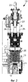
фиг.1 изображает фронтальную проекцию одного варианта осуществления тянуще-правильной установки, соответствующей настоящему изобретению,figure 1 depicts a front view of one embodiment of a pull-correct installation, corresponding to the present invention,
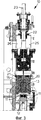
фиг.2 изображает частичное сечение по линии I-I фиг.1 для первого рабочего состояния,figure 2 depicts a partial section along the line I-I of figure 1 for the first working condition,
фиг.3 изображает частичное сечение по линии I-I фиг.1 для второго рабочего состояния,figure 3 depicts a partial section along the line I-I of figure 1 for the second operational state,
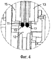
фиг.4 изображает увеличенный фрагмент фиг.2,figure 4 depicts an enlarged fragment of figure 2,
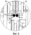
фиг.5 изображает увеличенный фрагмент фиг.3.figure 5 depicts an enlarged fragment of figure 3.
Осуществление изобретенияThe implementation of the invention
Соответствующая настоящему изобретению и прилагаемым чертежам тянуще-правильная установка 10 может быть с успехом применена в гибочном/формующем станке, например в станке (не показан) для изготовления арматурных хомутов, а также в иных ситуациях, когда в станок осуществляется одновременная подача по меньшей мере двух металлических проволок или заготовок 11 круглого сечения.According to the present invention and the accompanying drawings, the pull-
Тянуще-правильная установка 10 согласно настоящему изобретению содержит тянущий (приводной) ролик 12, два внешних встречных ролика 13, два внутренних встречных ролика 15 и в данном случае несколько натяжных роликов 16, расположенных до и после встречных роликов 13 и 15 относительно направления F подачи металлических круглых заготовок 11.The pulling-
В частности, тянущий ролик 12 имеет одиночное тянущее колесо, периферия которого снабжена двумя круговыми ручьями, соответственно внешним ручьем 17 и внутренним ручьем 19, при этом оба ручья имеют по существу V-образное сечение и их размер выбран сообразно номинальному диаметру подаваемых металлических круглых заготовок 11.In particular, the
Натяжные ролики 16 - в сущности традиционного типа и далее подробно не описываются.Tension rollers 16 are essentially of a traditional type and are not described in detail further.
Встречные ролики 13 и 15 расположены на противоположной стороне тянущего ролика 12 относительно оси F подачи металлических круглых заготовок 11.
Встречные ролики 13 и 15 установлены на подвижной опоре 22, выполненной с возможностью перемещения вместе со встречными роликами 13 и 15 в направлении тянущего ролика 12 с целью занятия заданного начального положения, зависящего от размеров металлических круглых заготовок 11.
Подвижная опора 22 выполнена с возможностью выборочного перемещения посредством винтовой передачи 23, управляемой элементом (не показан) привода.The
В соответствии с одним вариантом осуществления изобретения подвижная опора 22 амортизирована упругими элементами, например тарельчатыми пружинами, с целью поглощения ударов по встречным роликам 13 и 15, которые вызваны неоднородностями поверхностей и/или вибрацией металлических заготовок 11.In accordance with one embodiment of the invention, the
В рассматриваемом случае внешние встречные ролики 13 установлены на подвижной опоре 22 посредством связанного с ним внешнего ползуна 20, в то время как внутренние встречные ролики 15 установлены на подвижной опоре 22 посредством связанного с ним внутреннего ползуна 21.In the case under consideration, the
Внешний ползун 20 и внутренний ползун 21 отделены друг от друга и могут перемещаться независимо друг от друга.The
В частности, каждый ползун 20 и 21 функционально связан с соответствующим линейным приводом 25 и 26, установленным на подвижной опоре 22. Каждый линейный привод 25 и 26 выполнен с возможностью перемещения соответствующего ползуна 20, 21 относительно подвижной опоры 22 независимо от другого ползуна.In particular, each
Перемещение, задаваемое каждым из линейных приводов 25, 26, позволяет по существу непрерывно, без предварительного задания ограничений, с высокой степенью точности и чувствительности осуществлять компенсацию возможных вариаций диаметра металлических круглых заготовок 11 относительно их номинального размера, гарантируя постоянство условий поджатия и подачи.The movement specified by each of the
Как можно видеть, в частности, из сравнения фиг.4 и 5, когда две металлические круглые заготовки 11 имеют по существу одинаковую угловую ориентацию, два поджимающих ролика 13 и 15 находятся по существу на одинаковом расстоянии от тянущего ролика 12.As can be seen, in particular, from a comparison of FIGS. 4 and 5, when two metal round billets 11 have substantially the same angular orientation, the two
С другой стороны, когда одна из двух металлических круглых заготовок 11 (в данном случае левая) ориентирована по углу иначе, чем другая заготовка, разница в диаметрах компенсируется не приложением избыточного усилия, а восполняется перемещением внутреннего встречного ролика 15 вниз.On the other hand, when one of the two metal round billets 11 (in this case, the left one) is oriented differently from the other angle, the difference in diameters is not compensated by the application of excessive force, but is compensated by moving the
Это перемещение совершается соответствующим линейным приводом 25 до тех пор, пока внутренний встречный ролик 15 не создаст нормальное усилие поджатия металлической круглой заготовки 11. Условия создания данного усилия по существу эквивалентны условиям для усилия поджатия, которое прикладывается со стороны внешнего встречного ролика 13.This movement is accomplished by the corresponding
Понятно, что в вышеописанной тянуще-правильной установке 10 могут быть произведены изменения и/или добавлены детали и узлы, не выходящие за границы идеи и объема изобретения.It is clear that in the above pull-
Например, в рамках настоящего изобретения можно предусмотреть, чтобы вместо двух ползунов 20 и 21 подвижная опора 22 была выполнена так, чтобы состояла из двух независимых друг от друга подвижных узлов, каждый из которых несет на себе соответствующий встречный ролик 13 или 15.For example, within the framework of the present invention, it can be envisaged that instead of two
При таком техническом решении могут быть предусмотрены две независимые винтовые передачи 23 или два привода другого типа, которые могут обеспечивать и совместное перемещение обоих встречных роликов 13 и 15, и компенсационное перемещение каждого встречного ролика 13 или 15 во время подачи заготовок, чтобы обеспечить постоянство усилия поджатия металлических круглых заготовок 11.With this technical solution, two independent
Согласно одному варианту осуществления изобретения управление включением одного или другого из двух линейных приводов 25 и 26 осуществляется вручную оператором.According to one embodiment of the invention, the activation of one or the other of the two
Согласно другому варианту осуществления изобретения управление включением одного или другого из двух линейных приводов 25 и 26 осуществляется чувствительными элементами и/или контроллерами усилия каждого линейного привода 25 и 26, так чтобы привод всегда создавал одно и то же рабочее усилие.According to another embodiment of the invention, the actuation of one or the other of the two
Согласно еще одному варианту осуществления изобретения управление двумя линейными приводами 25 и 26 осуществляется выборочно посредством оптических датчиков, контролирующих угловую ориентацию металлических круглых заготовок 11.According to another embodiment of the invention, the control of the two
В соответствии с другим вариантом вместо линейных приводов 25 и 26 предусмотрены элементы в виде мотора, выполненные с возможностью независимого перемещения двух встречных роликов 13 и 15, чем гарантируется неизменно одинаковое рабочее усилие на соответствующих металлических круглых заготовках 11.In accordance with another embodiment, instead of
Еще один вариант заключается в применении настоящего изобретения к традиционной тянущей установке, не содержащей натяжных роликов 16 и состоящей по существу из одного или более тянущих роликов 12 и соответствующих внешнего встречного ролика 13 и внутреннего встречного ролика 15.Another option is to apply the present invention to a traditional pulling installation that does not contain tension rollers 16 and consisting essentially of one or more pulling
Согласно одному из вариантов каждый встречный ролик 13, 15 механически связан с упругими элементами с целью поглощения возможных вибраций или скачков, вызванных неровностями поверхностей металлических круглых заготовок 11.According to one embodiment, each
В рамках настоящего изобретения можно также предусмотреть две винтовые передачи 23, выполненные с возможностью грубого перемещения встречных роликов 13 и 15 для сближения с тянущим роликом 12, и два линейных привода 25 и 26, выполненных с возможностью точного перемещения встречных роликов 13 и 15, чтобы неизменно гарантировать постоянство усилия поджатия, которое прикладывается к металлическим круглым заготовкам.In the framework of the present invention, it is also possible to provide two
Хотя настоящее изобретение было описано на примерах конкретных предпочтительных вариантов, для специалистов в данной области должно быть понятно, что может быть получено много других эквивалентных форм тянуще-правильной установки для длинномерных металлических изделий, таких как прутки, изделия круглого сечения или металлическая проволока, с отличительными признаками, изложенными в пунктах формулы изобретения и, следовательно, подпадающими под объем охраны настоящего изобретения.Although the present invention has been described by way of examples of specific preferred embodiments, it will be understood by those skilled in the art that many other equivalent forms of pull-right installation can be obtained for long metal products, such as rods, circular products or metal wire, with distinctive the features set forth in the claims and, therefore, falling within the scope of protection of the present invention.
Claims (8)
Applications Claiming Priority (3)
| Application Number | Priority Date | Filing Date | Title |
|---|---|---|---|
| ITUD2008A000216A IT1391890B1 (en) | 2008-10-14 | 2008-10-14 | TOWING AND / OR STRAIGHTENING GROUP FOR OBLUNG METAL PRODUCTS, SUCH AS BARS, ROUNDS OR METAL WIRES |
| ITUD2008A000216 | 2008-10-14 | ||
| PCT/EP2009/063339 WO2010043611A1 (en) | 2008-10-14 | 2009-10-13 | Drawing and/or straightening unit for oblong metal products, such as bars, round pieces or metal wire |
Publications (2)
| Publication Number | Publication Date |
|---|---|
| RU2011118232A RU2011118232A (en) | 2012-11-27 |
| RU2529599C2 true RU2529599C2 (en) | 2014-09-27 |
Family
ID=40678843
Family Applications (1)
| Application Number | Title | Priority Date | Filing Date |
|---|---|---|---|
| RU2011118232/02A RU2529599C2 (en) | 2008-10-14 | 2009-10-13 | Draw-and-straighten plant for long metal articles such as bars, round-section parts or metal wire |
Country Status (18)
| Country | Link |
|---|---|
| US (1) | US9555465B2 (en) |
| EP (2) | EP3153248B1 (en) |
| JP (1) | JP5800317B2 (en) |
| CN (1) | CN102215998B (en) |
| AU (1) | AU2009305430B2 (en) |
| BR (1) | BRPI0919610B1 (en) |
| CA (1) | CA2740208C (en) |
| DK (2) | DK2349606T3 (en) |
| ES (2) | ES2763536T3 (en) |
| HR (1) | HRP20170227T1 (en) |
| HU (2) | HUE031898T2 (en) |
| IT (1) | IT1391890B1 (en) |
| LT (1) | LT2349606T (en) |
| PL (2) | PL2349606T3 (en) |
| PT (2) | PT3153248T (en) |
| RU (1) | RU2529599C2 (en) |
| SI (1) | SI2349606T1 (en) |
| WO (1) | WO2010043611A1 (en) |
Cited By (1)
| Publication number | Priority date | Publication date | Assignee | Title |
|---|---|---|---|---|
| RU2799466C2 (en) * | 2019-02-28 | 2023-07-05 | Эвг Энтвиклюнгс- У. Фервертунгс-Гезелльшафт М.Б.Х. | Method and device for aligning wire or tape |
Families Citing this family (12)
| Publication number | Priority date | Publication date | Assignee | Title |
|---|---|---|---|---|
| IT1401850B1 (en) * | 2010-10-14 | 2013-08-28 | Schnell Spa | TOWING GROUP IN MACHINES TO WORK METAL PROFILES |
| CN102431697B (en) * | 2011-09-16 | 2013-07-03 | 建科机械(天津)股份有限公司 | Adjustable-vibration material storing device of steel bar straightening and cutting machine |
| ITUD20110178A1 (en) * | 2011-11-09 | 2013-05-10 | Fabro Giorgio Del | TOWING DEVICE FOR METAL PRODUCTS, SUCH AS BARS, ROUNDS OR METALLIC WIRES |
| CN103056246B (en) * | 2013-01-30 | 2014-12-10 | 建科机械(天津)股份有限公司 | Anti-torsion steel bar feeding mechanism |
| ITUD20130029A1 (en) * | 2013-02-28 | 2014-08-29 | Piegatrici Macch Elettr | TOWING AND STRAIGHTENING SYSTEM FOR METAL WIRES, AND ITS PROCEDURE OF TOWING AND STRAIGHTENING |
| ES2552584B1 (en) * | 2014-05-27 | 2016-09-14 | Mariano Camps I Fills, S.L. | Metal wire fiber forming machine and corresponding set |
| BR102014015085B1 (en) | 2014-05-29 | 2023-11-14 | M.E.P. Macchine Elettroniche Piegatrici S.P.A. | Drawing unit, drawing apparatus and corresponding method |
| CN106141028B (en) * | 2016-07-27 | 2023-06-16 | 姜勇 | Hoop bending machine with eccentric shaft type pressing mechanism |
| CN106141027B (en) * | 2016-07-27 | 2018-02-16 | 姜勇 | A kind of arc line sending autobalance hoop bender |
| IT201600117662A1 (en) * | 2016-11-22 | 2018-05-22 | A C M Srl Automatismi Costruzioni Mecc | Multifunctional work apparatus |
| CN110756702A (en) * | 2019-11-04 | 2020-02-07 | 潘萍儿 | Steel wire cutting machine |
| IT202000023467A1 (en) * | 2020-10-06 | 2022-04-06 | M E P Macch Elettroniche Piegatrici Spa | GROUP AND RELATIVE TOWING METHOD FOR METALLIC PRODUCTS |
Citations (4)
| Publication number | Priority date | Publication date | Assignee | Title |
|---|---|---|---|---|
| DE9408880U1 (en) * | 1994-03-31 | 1994-09-01 | Jaeger Emil Gmbh Co Kg | Feed device for longitudinal wires with double-sided drive |
| RU2067037C1 (en) * | 1993-06-24 | 1996-09-27 | Белорусский Металлургический Завод | Method of making wire for metallic cord and drawbench for performing the method |
| EP0689884B1 (en) * | 1994-06-30 | 2000-07-12 | SMS Demag AG | Roller straightening machine for the straightening of profiles |
| WO2007141273A1 (en) * | 2006-06-08 | 2007-12-13 | M.E.P. Macchine Elettroniche Piegatrici Spa | Bending machine for bars, particularly bars fed from a roll, and relative method |
Family Cites Families (17)
| Publication number | Priority date | Publication date | Assignee | Title |
|---|---|---|---|---|
| AT259334B (en) * | 1964-03-24 | 1968-01-10 | Dalmine Spa | Device for straightening rods, pipes and. like |
| US4022046A (en) * | 1973-12-03 | 1977-05-10 | Nippon Steel Corporation | Method of and apparatus for straightening steel sections |
| SU772647A1 (en) * | 1979-04-26 | 1980-10-23 | Всесоюзный Ордена Ленина Научно- Исследовательский И Проектно-Кон- Структорский Институт Металлургического Машиностроения | Plant for continuous straightening of rolled stock |
| US4829801A (en) * | 1986-11-03 | 1989-05-16 | Mcraine Lance W | Cable straightening apparatus |
| IT1235174B (en) * | 1989-01-18 | 1992-06-23 | Piegatrici Macch Elettr | ORTHOGONAL ADJUSTMENT GROUP AND PROCEDURE FOR THE ORTHOGONAL ADJUSTMENT OF STRAIGHTENED PROFILES |
| IT1239667B (en) * | 1990-03-15 | 1993-11-11 | Mep Macchine Elettroniche Piegatrici | COMBINED GROUP OF PROFILE STRAIGHTENING AND LINEARIZATION |
| JPH06328249A (en) * | 1993-05-19 | 1994-11-29 | Nippon Steel Corp | Wire straighening device of arc welding equipment |
| US5758533A (en) * | 1994-04-15 | 1998-06-02 | Clecim | Imbricated roll planisher and process for its use |
| IT1267278B1 (en) * | 1994-07-20 | 1997-01-28 | Piegatrici Macch Elettr | COMPENSATING DEVICE FOR THE ELONGATION OF AT LEAST TWO WIRES, OR RODS, ASSOCIATED WITH A TRIGGERING GROUP |
| DE4442483A1 (en) * | 1994-11-29 | 1996-05-30 | Suspa Spannbeton Gmbh | Introduction of steel reinforcement rods into common concrete pipe |
| FR2739578B1 (en) * | 1995-10-06 | 1998-01-02 | Clecim Sa | PARALLEL CYLINDER PLANER |
| IT1288966B1 (en) * | 1996-08-09 | 1998-09-25 | Piegatrici Macch Elettr | TOWING GROUP FOR BENDING MACHINES |
| CN2530746Y (en) * | 2002-01-22 | 2003-01-15 | 燕山大学 | Hot rolling twisted steel straightening cut-off machine |
| CN2696874Y (en) * | 2004-04-12 | 2005-05-04 | 张海勇 | Rim corrector |
| CH697624B1 (en) * | 2005-02-23 | 2008-12-31 | Main Man Inspiration Ag | Rolling device for an in-line rolling of a produced by strip casting, in particular twin-roll strip casting steel strip. |
| US7637133B2 (en) * | 2006-07-13 | 2009-12-29 | Butech Bliss | Cassette roller leveler with common back-up rolls |
| CN200963659Y (en) * | 2006-10-23 | 2007-10-24 | 宋保安 | Machine for straightening and cutting steel bar |
-
2008
- 2008-10-14 IT ITUD2008A000216A patent/IT1391890B1/en active
-
2009
- 2009-10-13 PT PT161986419T patent/PT3153248T/en unknown
- 2009-10-13 AU AU2009305430A patent/AU2009305430B2/en active Active
- 2009-10-13 BR BRPI0919610-2A patent/BRPI0919610B1/en active IP Right Grant
- 2009-10-13 DK DK09740293.7T patent/DK2349606T3/en active
- 2009-10-13 WO PCT/EP2009/063339 patent/WO2010043611A1/en active Application Filing
- 2009-10-13 PL PL09740293T patent/PL2349606T3/en unknown
- 2009-10-13 JP JP2011531470A patent/JP5800317B2/en active Active
- 2009-10-13 ES ES16198641T patent/ES2763536T3/en active Active
- 2009-10-13 CN CN200980145576.4A patent/CN102215998B/en active Active
- 2009-10-13 EP EP16198641.9A patent/EP3153248B1/en active Active
- 2009-10-13 HU HUE09740293A patent/HUE031898T2/en unknown
- 2009-10-13 ES ES09740293.7T patent/ES2615955T3/en active Active
- 2009-10-13 CA CA2740208A patent/CA2740208C/en active Active
- 2009-10-13 DK DK16198641.9T patent/DK3153248T3/en active
- 2009-10-13 HU HUE16198641A patent/HUE047886T2/en unknown
- 2009-10-13 LT LTEP09740293.7T patent/LT2349606T/en unknown
- 2009-10-13 RU RU2011118232/02A patent/RU2529599C2/en active
- 2009-10-13 EP EP09740293.7A patent/EP2349606B1/en active Active
- 2009-10-13 SI SI200931611A patent/SI2349606T1/en unknown
- 2009-10-13 PL PL16198641T patent/PL3153248T3/en unknown
- 2009-10-13 US US13/124,394 patent/US9555465B2/en active Active
- 2009-10-13 PT PT97402937T patent/PT2349606T/en unknown
-
2017
- 2017-02-13 HR HRP20170227TT patent/HRP20170227T1/en unknown
Patent Citations (4)
| Publication number | Priority date | Publication date | Assignee | Title |
|---|---|---|---|---|
| RU2067037C1 (en) * | 1993-06-24 | 1996-09-27 | Белорусский Металлургический Завод | Method of making wire for metallic cord and drawbench for performing the method |
| DE9408880U1 (en) * | 1994-03-31 | 1994-09-01 | Jaeger Emil Gmbh Co Kg | Feed device for longitudinal wires with double-sided drive |
| EP0689884B1 (en) * | 1994-06-30 | 2000-07-12 | SMS Demag AG | Roller straightening machine for the straightening of profiles |
| WO2007141273A1 (en) * | 2006-06-08 | 2007-12-13 | M.E.P. Macchine Elettroniche Piegatrici Spa | Bending machine for bars, particularly bars fed from a roll, and relative method |
Cited By (1)
| Publication number | Priority date | Publication date | Assignee | Title |
|---|---|---|---|---|
| RU2799466C2 (en) * | 2019-02-28 | 2023-07-05 | Эвг Энтвиклюнгс- У. Фервертунгс-Гезелльшафт М.Б.Х. | Method and device for aligning wire or tape |
Also Published As
Similar Documents
| Publication | Publication Date | Title |
|---|---|---|
| RU2529599C2 (en) | Draw-and-straighten plant for long metal articles such as bars, round-section parts or metal wire | |
| EP3127629B1 (en) | Device for manufacturing hot-rolled coil spring | |
| TWI466737B (en) | An apparatus for controlling the drive of a pay-off | |
| KR20170015985A (en) | Bending machine and corresponding method | |
| KR101727992B1 (en) | Drawing unit and corresponding apparatus and method | |
| JP2012035290A (en) | Straightening device of wire material | |
| CN103037997B (en) | Apparatus for manufacturing coil spring | |
| JP6461963B2 (en) | Cold pilger rolling mill and method for forming blanks into tubes | |
| TW201628813A (en) | Pressing roller adjustment device for processing machinery, especially slot machines, and processing machinery, especially slot machines with adjustment device | |
| KR100908981B1 (en) | Pipe Forming Machine with Banding Function | |
| RU2552206C2 (en) | Method of thermal-and-force processing of long axially symmetric parts and device to this end | |
| CN104878168A (en) | Surface-treated component manufacturing method and apparatus | |
| US9744584B2 (en) | Hot formed coiling machine | |
| CN210701693U (en) | Processing device for cold forming of metal special-shaped long material | |
| AU4241801A (en) | Device for producing metal fibers | |
| RU152120U1 (en) | PIPE BENDING MACHINE | |
| JP2015182121A (en) | Roll bender and bending method for long material | |
| CN104842166A (en) | Stainless steel pipe working machine | |
| RU2708488C1 (en) | Pipe-forming machine | |
| CN110538870B (en) | Processing device and processing technology for cold forming of metal special-shaped long material and product | |
| JP2019025517A (en) | Correcting method and correcting machine | |
| JP6155877B2 (en) | Screw rolling method | |
| CN109152474A (en) | Equipment for manufacturing circle brush | |
| ITUD20120211A1 (en) | TOWING AND / OR STRAIGHTENING EQUIPMENT FOR OBLUNG METALLIC PRODUCTS, SUCH AS BARS, ROUNDS OR METAL WIRES, BENDING MACHINE INCLUDING THE MACHINE AND ITS PROCEDURE OF TOWING AND / OR STRAIGHTENING | |
| UA26468U (en) | Tube-cutting automatic machine |
Legal Events
| Date | Code | Title | Description |
|---|---|---|---|
| HE9A | Changing address for correspondence with an applicant |