RU2524503C1 - Multifunctional training complex for spacemen training for works in open space - Google Patents
Multifunctional training complex for spacemen training for works in open space Download PDFInfo
- Publication number
- RU2524503C1 RU2524503C1 RU2013101081/11A RU2013101081A RU2524503C1 RU 2524503 C1 RU2524503 C1 RU 2524503C1 RU 2013101081/11 A RU2013101081/11 A RU 2013101081/11A RU 2013101081 A RU2013101081 A RU 2013101081A RU 2524503 C1 RU2524503 C1 RU 2524503C1
- Authority
- RU
- Russia
- Prior art keywords
- input
- output
- module
- electric drive
- sensor
- Prior art date
Links
- 238000012549 training Methods 0.000 title claims abstract description 167
- 238000004891 communication Methods 0.000 claims abstract description 74
- 230000000694 effects Effects 0.000 claims abstract description 57
- 239000000725 suspension Substances 0.000 claims description 70
- 238000012800 visualization Methods 0.000 claims description 57
- 230000009347 mechanical transmission Effects 0.000 claims description 45
- 230000001133 acceleration Effects 0.000 claims description 35
- 238000004088 simulation Methods 0.000 claims description 29
- 238000013016 damping Methods 0.000 claims description 19
- 238000012544 monitoring process Methods 0.000 claims description 19
- 238000002360 preparation method Methods 0.000 claims description 18
- 230000005540 biological transmission Effects 0.000 claims description 14
- 238000005303 weighing Methods 0.000 claims description 13
- 239000011521 glass Substances 0.000 claims description 12
- 238000003032 molecular docking Methods 0.000 claims description 10
- 230000007704 transition Effects 0.000 claims description 10
- 230000007246 mechanism Effects 0.000 claims description 8
- 238000006073 displacement reaction Methods 0.000 claims description 7
- 230000006870 function Effects 0.000 claims description 5
- 230000021615 conjugation Effects 0.000 claims description 3
- 230000008878 coupling Effects 0.000 claims description 2
- 238000010168 coupling process Methods 0.000 claims description 2
- 238000005859 coupling reaction Methods 0.000 claims description 2
- 230000002085 persistent effect Effects 0.000 claims description 2
- 239000000126 substance Substances 0.000 abstract 1
- 238000000034 method Methods 0.000 description 31
- 230000005484 gravity Effects 0.000 description 25
- PEDCQBHIVMGVHV-UHFFFAOYSA-N Glycerine Chemical compound OCC(O)CO PEDCQBHIVMGVHV-UHFFFAOYSA-N 0.000 description 17
- 238000013461 design Methods 0.000 description 16
- 238000007726 management method Methods 0.000 description 14
- 230000008569 process Effects 0.000 description 14
- 210000003128 head Anatomy 0.000 description 12
- 238000005516 engineering process Methods 0.000 description 11
- 230000009471 action Effects 0.000 description 8
- 238000010586 diagram Methods 0.000 description 8
- 230000002452 interceptive effect Effects 0.000 description 8
- 230000003190 augmentative effect Effects 0.000 description 5
- 238000009434 installation Methods 0.000 description 5
- 239000000203 mixture Substances 0.000 description 5
- 238000011160 research Methods 0.000 description 5
- 238000012423 maintenance Methods 0.000 description 4
- 230000003304 psychophysiological effect Effects 0.000 description 4
- 230000001360 synchronised effect Effects 0.000 description 4
- 238000012360 testing method Methods 0.000 description 4
- 230000000007 visual effect Effects 0.000 description 4
- 230000008859 change Effects 0.000 description 3
- 238000012937 correction Methods 0.000 description 3
- 238000011161 development Methods 0.000 description 3
- 238000007654 immersion Methods 0.000 description 3
- 239000000463 material Substances 0.000 description 3
- 230000003387 muscular Effects 0.000 description 3
- 230000008439 repair process Effects 0.000 description 3
- 230000029058 respiratory gaseous exchange Effects 0.000 description 3
- 238000012546 transfer Methods 0.000 description 3
- 238000009423 ventilation Methods 0.000 description 3
- 101100264172 Oryza sativa subsp. japonica XIAO gene Proteins 0.000 description 2
- 238000007792 addition Methods 0.000 description 2
- 238000010276 construction Methods 0.000 description 2
- 239000000428 dust Substances 0.000 description 2
- 239000012634 fragment Substances 0.000 description 2
- 230000003993 interaction Effects 0.000 description 2
- 239000007788 liquid Substances 0.000 description 2
- 230000007774 longterm Effects 0.000 description 2
- 230000008520 organization Effects 0.000 description 2
- 230000004044 response Effects 0.000 description 2
- 230000035807 sensation Effects 0.000 description 2
- 239000002689 soil Substances 0.000 description 2
- 238000003860 storage Methods 0.000 description 2
- 239000013598 vector Substances 0.000 description 2
- XLYOFNOQVPJJNP-UHFFFAOYSA-N water Substances O XLYOFNOQVPJJNP-UHFFFAOYSA-N 0.000 description 2
- 101100283975 Bos taurus GSTM1 gene Proteins 0.000 description 1
- BUGBHKTXTAQXES-UHFFFAOYSA-N Selenium Chemical compound [Se] BUGBHKTXTAQXES-UHFFFAOYSA-N 0.000 description 1
- 238000004458 analytical method Methods 0.000 description 1
- 238000005452 bending Methods 0.000 description 1
- 230000008901 benefit Effects 0.000 description 1
- 230000036760 body temperature Effects 0.000 description 1
- 238000006243 chemical reaction Methods 0.000 description 1
- 238000010835 comparative analysis Methods 0.000 description 1
- 230000000052 comparative effect Effects 0.000 description 1
- 230000009189 diving Effects 0.000 description 1
- 238000005562 fading Methods 0.000 description 1
- 210000001061 forehead Anatomy 0.000 description 1
- 238000009432 framing Methods 0.000 description 1
- 231100001261 hazardous Toxicity 0.000 description 1
- 230000036541 health Effects 0.000 description 1
- 238000003384 imaging method Methods 0.000 description 1
- 238000002955 isolation Methods 0.000 description 1
- 230000009916 joint effect Effects 0.000 description 1
- 210000003127 knee Anatomy 0.000 description 1
- 230000002045 lasting effect Effects 0.000 description 1
- 210000002414 leg Anatomy 0.000 description 1
- 238000004519 manufacturing process Methods 0.000 description 1
- 238000012986 modification Methods 0.000 description 1
- 230000004048 modification Effects 0.000 description 1
- 210000003205 muscle Anatomy 0.000 description 1
- 230000007935 neutral effect Effects 0.000 description 1
- 238000005457 optimization Methods 0.000 description 1
- 210000000056 organ Anatomy 0.000 description 1
- 230000003071 parasitic effect Effects 0.000 description 1
- 238000012545 processing Methods 0.000 description 1
- 230000005855 radiation Effects 0.000 description 1
- 230000035484 reaction time Effects 0.000 description 1
- 230000001020 rhythmical effect Effects 0.000 description 1
- 238000007665 sagging Methods 0.000 description 1
- 239000004576 sand Substances 0.000 description 1
- 229910052711 selenium Inorganic materials 0.000 description 1
- 239000011669 selenium Substances 0.000 description 1
- 230000003238 somatosensory effect Effects 0.000 description 1
- 238000013519 translation Methods 0.000 description 1
- CZPRKINNVBONSF-UHFFFAOYSA-M zinc;dioxido(oxo)phosphanium Chemical compound [Zn+2].[O-][P+]([O-])=O CZPRKINNVBONSF-UHFFFAOYSA-M 0.000 description 1
Images

Landscapes
- Manipulator (AREA)
- Rehabilitation Tools (AREA)
Abstract
Description
Изобретение относится к разделу пилотируемой космонавтики и предназначено для подготовки космонавтов (астронавтов) экипажей МКС к внекорабельной деятельности (подготовка и выход в космос, выполнение перемещений и различных технологических операций) в условиях полной невесомости открытого космического пространства, а также в условиях пониженной гравитации на спутнике Земли Луне и на других космических объектах Солнечной системы.The invention relates to the field of manned space exploration and is intended for the preparation of astronauts (astronauts) of the ISS crews for extra-ship activity (preparation and entry into space, performing displacements and various technological operations) under conditions of complete zero gravity of open space, as well as in conditions of reduced gravity on the Earth’s satellite The moon and other space objects of the solar system.
Известна «Многофункциональная система имитации космического корабля» (Европейская патентная заявка CN 202042069 U MULTI-ROLE SPACE SIMULATION SYSTEM AND SPACE SHIP SIMULATION SYSTEM, Int. Class.: G09B 9/52, H04L 29/06, Priority Data: 05.03.2011, Applicants: BEIJING SUPER VIEW TECHNOLOGY CO LTD [CN]), содержащая систему имитации бортовых систем космического корабля и отдельных факторов космического пространства, функционирующую на базе сервера, сетевые коммуникационные устройства и персональные компьютеры обучаемых с основным и дополнительным дисплеями и с устройством управления компьютером.The well-known "Multifunctional spacecraft simulation system" (European patent application CN 202042069 U MULTI-ROLE SPACE SIMULATION SYSTEM AND SPACE SHIP SIMULATION SYSTEM, Int. Class .: G09B 9/52,
Известен также «Стенд подготовки экипажей международной космической станции с использованием элементов виртуальной реальности» (см. Web-страницу ФГБУ «НИИ ЦПК им. Ю.А. Гагарина»: http://www.gctc.ru/main.php?id=135), обеспечивающий моделирование бортовых систем и погружение в виртуальный мир Российского сегмента Международной космической станции, а также отработку группового взаимодействия членов экипажа при их совместной работе по эксплуатации и ремонту бортовых систем.Also known is the “Stand for the training of the crews of the international space station using virtual reality elements” (see the web page of the FSBI NII TsPK named after Yu.A. Gagarin: http://www.gctc.ru/main.php?id= 135), providing modeling of on-board systems and immersion in the virtual world of the Russian segment of the International Space Station, as well as working out group interaction of crew members during their joint work on the operation and repair of on-board systems.
Недостатком данной системы и стенда является то, что они, относясь к автоматизированным обучающим системам, использующим синтезированные изображения бортового оборудования и визуализацию отдельных факторов космического пространства (на базе технологий виртуальной реальности), предназначены, преимущественно, для теоретической и первоначальной практической подготовки (так называемой предтренажерной подготовки: знакомство с устройством космического аппарата и принципами его управления, привитие первоначальных навыков по управлению космическим аппаратом, визуализация процессов и явлений космического пространства и т.д.). В составе этих систем отсутствуют штатные органы управления и средства отображения информации (или органы управления и средства отображения информации в тренажном исполнении, внешне полностью идентичные штатным), что не позволяет обеспечить приобретение обучаемыми операторами устойчивых перцептуальных и сенсорно-моторных навыков по управлению космическим аппаратом. В то же время огромным преимуществом систем, использующих технологии виртуальной реальности, является практически неограниченная возможность наглядной демонстрации обучаемым космического пространства и условий космического полета, например невесомости, солнечной радиации, перепада температур, метеорной пыли, космического мусора и т.д.The disadvantage of this system and stand is that they, referring to automated training systems using synthesized images of on-board equipment and visualization of individual space factors (based on virtual reality technologies), are intended primarily for theoretical and initial practical training (the so-called pre-training training: familiarity with the device of the spacecraft and the principles of its management, instilling the initial management skills spacecraft, visualization of processes and phenomena of outer space, etc.). These systems lack full-time controls and information display facilities (or controls and information displays in a simulator version that are outwardly completely identical to regular ones), which does not allow the trained operators to acquire stable perceptual and sensory-motor skills in controlling the spacecraft. At the same time, the huge advantage of systems using virtual reality technology is the almost unlimited ability for students to demonstrate space and space flight conditions, such as weightlessness, solar radiation, temperature differences, meteor dust, space debris, etc.
Кроме этого, в рассмотренных выше технических средствах обучения («Многофункциональная система имитации космического корабля» и «Стенд подготовки экипажей международной космической станции с использованием элементов виртуальной реальности») отсутствует имитация такого важного фактора космического полета, как состояния невесомости и соответственно не обеспечивается приобретение обучаемыми космонавтами (астронавтами) перцептуальных и сенсорно-моторных навыков при выполнении операций в открытом космосе в процессе осуществлении внекорабельной деятельности.In addition, the technical training tools discussed above (“Multifunctional system for simulating a spacecraft” and “Stand for training crews of an international space station using virtual reality elements”) do not simulate such an important factor in space flight as the state of zero gravity and, accordingly, the acquisition by trained astronauts is not ensured (astronauts) perceptual and sensory-motor skills when performing operations in outer space during ekorabelnoy activities.
Известны устройства для моделирования пониженной силы тяжести (Международная патентная заявка № EP 1231139 DEVICE FOR THE SIMULATION OF VARIABLE GRAVITY ACCELERATIONS, IPC: B64D 47/00, B64G 7/00, Publication Date: 13.02.2001, Applicant: EADS SPACE TRANSP GMBH [DE]) и способ (Патент на изобретение РФ №2099256 СПОСОБ ПИЛОТИРОВАНИЯ ЛЕТАТЕЛЬНОГО АППАРАТА, СОВЕРШЕНСТВУЮЩИЙ СОСТОЯНИЕ ИСКУССТВЕННОЙ НЕВЕСОМОСТИ И СИСТЕМА ДЛЯ РЕАЛИЗАЦИИ ЭТОГО СПОСОБА, МПК 6: B64G 7/00, Опубликовано: 20.12.1997, Патентообладатель: Сантр Насьональ Д′Этюд Спасьаль (FR), а также летающие лаборатории (см. Web-страницу ФГБУ «НИИ ЦПК им. Ю.А. Гагарина»: http://www.gctc.ru/main.php?id=132), в которых для создания невесомости используется самолет, летящий по параболической траектории (по так называемой «параболе Кеплера»).Known devices for modeling reduced gravity (International Patent Application No. EP 1231139 DEVICE FOR THE SIMULATION OF VARIABLE GRAVITY ACCELERATIONS, IPC:
Основным недостатком данных устройств является сравнительная кратковременность имитации состояния невесомости (до 15 режимов невесомости, каждый длительностью ориентировочно 15-30 с, причем общее время пребывания в состоянии невесомости составляет не более 450 с), что позволяет обучаемым лишь ознакомиться с влиянием невесомости на организм, с особенностями пространственной ориентировки в безопорном пространстве и, в лучшем случае выполнить только некоторые простейшие операции из комплекса процедур многочасовой внекорабельной деятельности.The main disadvantage of these devices is the comparative short duration of simulating the state of weightlessness (up to 15 modes of weightlessness, each lasting approximately 15-30 s, and the total time spent in the state of weightlessness is not more than 450 s), which allows students to only get acquainted with the effect of weightlessness on the body, with features of spatial orientation in unsupported space and, at best, perform only some simple operations from a set of procedures for many hours of extra-ship activity STI.
Известны метод и устройство создания переменной силы тяжести с эффектом присутствия в виртуальной реальности (Международная патентная заявка № WO/2011/032363 METHOD AND APPARATUS OF VARIABLE G FORCE EXPERIENCE AND CREATE IMMERSIVE VR SENSATIONS, IPC: B64G 7/00, G09B 9/00, Publication Date: 24.03.2011, Applicant: XIAO, Quan [CN/CN]), а также устройство и метод для имитации ощущений, испытываемых в космическом пространстве (Международная патентная заявка № WO/2009/029657 APPARATUS AND METHOD OF SIMULATING A SOMATOSENSORY EXPERIENCE IN SPACE, IPC: B64G 7/00, Publication Date: 05.03.2009, Applicant: XIAO, Quan [CN/US]). Основным недостатком этих методов и устройств для их осуществления является необходимость использования гидросреды для обезвешивания обучаемого космонавта, помещенного в специально адаптированный для погружений в гидросреду космический скафандр.A known method and device for creating variable gravity with the effect of presence in virtual reality (International patent application No. WO / 2011/032363 METHOD AND APPARATUS OF VARIABLE G FORCE EXPERIENCE AND CREATE IMMERSIVE VR SENSATIONS, IPC:
Сравнительный анализ работы космонавтов в условиях открытого космоса и в гидросреде (см. Тренажерные комплексы и тренажеры. Технологии разработки и опыт эксплуатации / В.Е. Шукшунов, В.В. Циблиев, С.И. Потоцкий и др. Под ред. В.Е. Шукшунова. - М.: Машиностроение, 2005. - с.258-260) показывает, что при работе в гидросреде возникают дополнительные нагрузки на обучаемого (являющиеся предпосылками для привития некоторых так называемых «ложных навыков»), которые вызваны рядом факторов, основным из которых является гидродинамическое сопротивление жидкости как при движениях рук, так и особенно ощутимое гидродинамическое сопротивление при перемещениях обучаемых космонавтов в гидросреде, в то время как в открытом космосе перемещение осуществляется по инерции после кратковременного приложения усилия и продолжается без «замирания» из-за отсутствия каких-либо сил сопротивления. Кроме этого, при погружениях в гидросреду возникает необходимость закрепления на скафандре дополнительных грузов для создания нулевой плавучести, которые приводят к смещению его центра масс, что также несколько влияет на динамические характеристики при перемещении.A comparative analysis of the work of astronauts in open space and in a hydraulic environment (see Training complexes and simulators. Development technologies and operating experience / V.E. Shukshunov, V.V. Tsibliyev, S.I. Pototsky, etc. Edited by V. E. Shukshunova. - M .: Mashinostroenie, 2005. - p. 258-260) shows that when working in a hydraulic environment additional loads arise on the student (which are prerequisites for instilling some so-called "false skills"), which are caused by a number of factors, the main of which is the hydrodynamic resistance of a liquid both with hand movements, and a particularly noticeable hydrodynamic resistance during the movements of trained cosmonauts in the hydraulic medium, while in outer space the movement is carried out by inertia after a short application of force and continues without “fading” due to the absence of any resistance forces. In addition, when diving in a hydraulic medium, there is a need to secure additional weights on the spacesuit to create zero buoyancy, which lead to a displacement of its center of mass, which also slightly affects the dynamic characteristics when moving.
Наиболее близким по технической сущности аналогом, принятым в качестве прототипа предлагаемого изобретения, является система управления (Патент на изобретение РФ №2355039 СИСТЕМА УПРАВЛЕНИЯ ВЕРТИКАЛЬНЫМ ПЕРЕМЕЩЕНИЕМ ОБУЧАЕМОГО НА ТРЕНАЖЕРЕ ВЫХОДА В КОСМОС, МПК G09B 9/00 (2006.01). Дата начала отсчета срока действия патента: 12.12.2007, Патентообладатель: Государственное образовательное учреждение высшего профессионального образования "Южно-Российский государственный технический университет (Новочеркасский политехнический институт)" ГОУ ВПО ЮРГТУ (НПИ) (RU), содержащая скафандр с обучаемым, задатчик веса груза, датчик положения, индикатор нуля, индикатор отказа датчика усилия, задатчик момента электродвигателя, сумматор, устройство регулирования момента, электродвигатель, передаточное устройство, датчик усилия, блок выделения разности усилий, регулятор усилия, кнопка запуска коррекции, первый блок коррекции и ключ, датчик скорости и второй блок коррекции.The closest in technical essence analogue adopted as a prototype of the present invention is a control system (Patent for invention of the Russian Federation No. 2355039 VERTICAL MOVEMENT CONTROL SYSTEM TRAINED ON SPACE TRAINING SIMULATOR, IPC G09B 9/00 (2006.01). Patent start date : 12.12.2007, Patentee: State Educational Institution of Higher Professional Education "South Russian State Technical University (Novocherkassk Polytechnic Institute)" GOU VPO SRSTU (NPI) (RU), containing the suit with the trainee, load weight adjuster, position sensor, zero indicator, force sensor failure indicator, electric motor torque adjuster, adder, torque control device, electric motor, transmission device, force sensor, force difference allocation unit, force regulator, correction start button, first correction block and key, speed sensor and second correction block.
Данная система управления, предназначенная для создания тренажера по подготовке к выходу в космос обучаемого космонавта в стыковочном (переходном/шлюзовом) отсеке орбитального модуля Российского сегмента Международной космической станции и осуществлению его внекорабельной деятельности в открытом космосе, обеспечивает имитацию состояния невесомости в воздушной среде методом силокомпенсирующего обезвешивания космонавта в скафандре, перемещающегося в так называемом «безопорном пространстве».This control system, designed to create a simulator for training a trained cosmonaut in space in the docking (transition / lock) compartment of the orbital module of the Russian segment of the International Space Station and to carry out its extra-ship activity in outer space, imitates the state of zero gravity in the air using the method of force-compensating weightlessness astronaut in a spacesuit moving in the so-called "unsupported space."
Система управления вертикальным перемещением обучаемого на тренажере выхода в космос обладает следующими существенными недостатками:The control system for the vertical movement of a trainee on the spacecraft simulator has the following significant disadvantages:
- система обеспечивает создание условий безопорного пространства только для трех степеней свободы;- the system provides the creation of conditions of unsupported space for only three degrees of freedom;
- для скафандра с обучаемым использовано эффективное силокомпенсирующее обезвешивание активного типа только для вертикального перемещения, а в горизонтальной плоскости обеспечиваются перемещения лишь пассивного типа, то есть за счет мускульной силы самого обучаемого, которому приходится перемещать помимо своей массы вместе со скафандром (полезная масса), еще и массу тележки, на которой он подвешен, и массу моста, на котором подвешена тележка («паразитные» массы, перемещение которой отчасти способствует привитию в процессе тренировки определенных «ложных навыков»).- for the suit with the student, an effective force-compensating weightlessness of the active type was used only for vertical movement, and only the passive type of movement is ensured in the horizontal plane, that is, due to the muscular strength of the student himself, who has to move in addition to his mass along with the suit (useful weight), and the mass of the trolley on which it is suspended, and the mass of the bridge on which the trolley is suspended ("parasitic" masses, the movement of which partly contributes to the instillation of limited “false skills”).
Кроме этого, данная система управления не предоставляет ряд функций, необходимых для обеспечения профессионального уровня подготовки, которые характерны для современных технических средств обучения.In addition, this management system does not provide a number of functions necessary to ensure a professional level of training, which are characteristic of modern technical training aids.
Во-первых, не обеспечивает возможность предтренажерной подготовки космонавтов (астронавтов), во-вторых, не обеспечивает возможность отработки сложных технологических операций, как правило, выполняемых в открытом космическом пространстве совместными действиями двух членов экипажа МКС, так как предоставляет возможность подготовки только для одного обучаемого в скафандре, в-третьих, не предусматривает компоновку рабочей зоны обучаемых оборудованием, необходимым для получения перцептуальных и сенсорно-моторных навыков при работе как внутри орбитального модуля, так и в открытом космическом пространстве на орбите Земли, в том числе с космическим грузовым манипулятором Российского сегмента МКС, в-четвертых, не обеспечивает возможность имитации пониженной гравитации, свойственной перспективным для посещения человеком космическим объектам Солнечной системы (Луна, крупные астероиды, Марс, спутники Марса и т.д.), в-пятых, не обеспечивает жизнедеятельность обучаемого в скафандре, в-шестых, не обеспечивает психофизиологический контроль обучаемого в реальном масштабе времени, в-седьмых, не предусматривает возможность связи обучаемого с остальными тренируемыми членами экипажа МКС и имитации связи со специалистами Центра управления полетами, в-восьмых, не обеспечивает возможность телевизионного наблюдения за обучаемым, в-девятых, не предусматривает возможность моделирования светотеневой обстановки, характерной для космических объектов, которые находятся на орбите Земли, в-десятых, не предусматривает возможность контроля и управления ходом тренировки, в-одиннадцатых, не предоставляет обучаемым возможность визуализации ближнего окружающего пространства (космические аппараты) и дальнего космического пространства (Земля, Луна, Солнце и другие космические объекты) и, в-двенадцатых, персонал не обеспечивается оперативной и ремонтно-технологической связью.Firstly, it does not provide the possibility of pre-training training of astronauts (astronauts), and secondly, it does not provide the possibility of practicing complex technological operations, as a rule, performed in open space by joint actions of two ISS crew members, as it provides training for only one student in a spacesuit, thirdly, it does not provide for the layout of the working area trained by the equipment necessary to obtain perceptual and sensory-motor skills when working as in fourth, doesn’t provide the ability to simulate the reduced gravity inherent in space objects of the solar system that are promising for humans to visit (the Moon, large asteroids , Mars, Mars satellites, etc.), fifthly, it does not provide the trainee’s vital activity in a spacesuit, sixthly, it does not provide the psychophysiological control of the student in real time seventh, does not provide for the possibility of communication between the student and the rest of the trained ISS crew and simulate communication with the specialists of the Mission Control Center, eighth, does not provide the possibility of television monitoring of the student, ninth, does not provide for the possibility of modeling the cut-off situation characteristic of tenth of space objects, which are in the Earth’s orbit Imaging near ambient space (space vehicles) and long space (Earth, moon, sun and other space objects) and, Twelfth, operational personnel is not ensured and repair technology bond.
Целью изобретения является расширение функциональных возможностей предлагаемого многофункционального учебно-тренировочного комплекса для обеспечения эффективной подготовки космонавтов (астронавтов) к так называемой «внекорабельной деятельности» (подготовка в переходном - шлюзовом отсеке орбитального модуля МКС к выходу, выход в открытый космос, выполнение перемещений и различных технологических операций, включая работу с грузами, на орбите Земли в условиях имитируемого состояния «полной» невесомости открытого космического пространства), а также для подготовки космонавтов (астронавтов) к предстоящим перспективным миссиям на поверхность космических объектов Солнечной системы, имеющих пониженную (по сравнению с Землей) гравитацию.The aim of the invention is to expand the functionality of the proposed multifunctional training complex to ensure the effective preparation of astronauts (astronauts) for the so-called "extra-ship activity" (preparation in the transition - airlock compartment of the ISS orbital module for exit, EVA, moving and various technological operations, including cargo handling, in the Earth’s orbit under the conditions of a simulated state of “complete” zero gravity of open space space), as well as for preparing cosmonauts (astronauts) for upcoming promising missions to the surface of space objects in the solar system that have reduced (compared to Earth) gravity.
Поставленная цель (по 1-му варианту предлагаемого технического решения, обеспечивающего режим «Совместная внекорабельная деятельность двух обучаемых») достигается тем, что в многофункциональный учебно-тренировочный комплекс для подготовки космонавтов (астронавтов) к внекорабельной деятельности, состоящий из первого механического передаточного устройства, первого датчика усилия и первого скафандра, предназначенного для размещения обучаемого, введеныThe goal (according to the 1st version of the proposed technical solution providing the “Joint extra-ship activity of two trainees” mode) is achieved by the fact that in a multifunctional training complex for training astronauts (astronauts) for extra-ship activity, consisting of the first mechanical transmission device, the first force sensor and the first spacesuit designed to accommodate the learner, introduced
интегрирующая система, состоящая из мобильного автоматизированного рабочего места (АРМ), адаптера беспроводной связи, сетевого сервера, консоли оператора, первого блока цифровой связи, многоканального видеорегистратора, локальной вычислительной сети передачи данных, локальной вычислительной сети видеонаблюдения и аудиопрослушивания и локальной вычислительной сети цифровой связи; «Гидролаборатория» и «Молодежный образовательный Космоцентр»; функционально-моделирующий стенд предтренажерной подготовки, состоящий из АРМ руководителя обучения, АРМ обучаемых, первого блока устройств сопряжения с объектом, второго блока цифровой связи, действующего макета выходного космического скафандра, телекамеры наблюдения и первого модуля средств отображения информации коллективного пользования; комплект телекамер наблюдения, система визуализации, первый и второй модуль средств медицинского контроля, сервер моделирования; первый электромеханический модуль обезвешивания с 6-ю степенями свободы, состоящий из первого комплекса устройств сопряжения с объектом, первого комплекта конечных выключателей, первого датчика положения моста, первого датчика положения тележки, первого комплектного электропривода перемещения моста, первого комплектного электропривода перемещения тележки, первого комплектного электропривода вертикального перемещения, первого датчика ускорений и угловых отклонений, первого упорного подшипника, первого демпфирующего устройства, первого одностепенного шарнирного подвеса для поворота по крену, первого комплектного электропривода перемещения по крену, первого датчика угла положения по крену, первого датчика положения обезвешиваемого объекта по вертикали, первого одностепенного шарнирного подвеса для поворота по тангажу, первого комплектного электропривода перемещения по тангажу, первого датчика угла положения по тангажу и первого датчика угловых скоростей обезвешиваемого объекта; второй блок устройств сопряжения с объектом, модуль средств освещения, полномасштабный макет орбитального модуля МКС и второй скафандр, предназначенный для размещения обучаемого; второй электромеханический модуль обезвешивания с 6-ю степенями свободы, состоящий из второго комплекса устройств сопряжения с объектом, второго комплекта конечных выключателей, второго датчика положения моста, второго датчика положения тележки, второго комплектного электропривода перемещения моста, второго комплектного электропривода перемещения тележки, второго комплектного электропривода вертикального перемещения, второго механического передаточного устройства, второго датчика ускорений и угловых отклонений, второго упорного подшипника, второго датчика усилия, второго демпфирующего устройства, второго одностепенного шарнирного подвеса для поворота по крену, второго комплектного электропривода перемещения по крену, второго датчика угла положения по крену, второго датчика положения обезвешиваемого объекта по вертикали, второго одностепенного шарнирного подвеса для поворота по тангажу, второго комплектного электропривода перемещения по тангажу, второго датчика угла положения по тангажу и второго датчика угловых скоростей обезвешиваемого объекта; пульт контроля и управления, состоящий из АРМ инженера, АРМ инструктора, третьего блока цифровой связи, АРМ врача, панели управления средствами обеспечения жизнедеятельности и второго модуля средств отображения информации коллективного пользования; средства обеспечения жизнедеятельности и участок, имитирующий поверхность космического объекта Солнечной системы, с комплектом учебного оборудования.an integrating system consisting of a mobile workstation (AWS), a wireless adapter, a network server, an operator’s console, a first digital communications unit, a multi-channel video recorder, a local area network for data transmission, a local area network for video surveillance and audio listening, and a local area network for digital communications; “Hydrolaboratory” and “Youth Educational Cosmocenter”; a functional-modeling stand for pre-training preparation, consisting of the workstation of the head of training, the workstation of students, the first block of devices for interfacing with the object, the second block of digital communication, the current layout of the output space suit, the surveillance camera and the first module of the means for displaying information for collective use; a set of surveillance cameras, a visualization system, the first and second module of medical controls, a simulation server; the first electromechanical weightless module with 6 degrees of freedom, consisting of the first complex of devices for interfacing with the object, the first set of limit switches, the first bridge position sensor, the first trolley position sensor, the first complete electric drive for moving the bridge, the first complete electric drive for moving the trolley, the first complete electric drive vertical movement, the first acceleration and angular deviation sensor, the first thrust bearing, the first damping device, ne a first single-stage articulated suspension for tilting the roll, the first complete roll electric drive of the roll, the first roll angle sensor, the first vertical position sensor of the weighted object, the first single-stage hinged suspension for turning the pitch, the first complete pitch electric drive, the first angle sensor pitch position and the first angular velocity sensor of the object being weighted; the second block of devices for interfacing with an object, a module of lighting equipment, a full-scale model of the ISS orbital module, and a second spacesuit designed to accommodate a student; a second electromechanical weighing module with 6 degrees of freedom, consisting of a second set of devices for interfacing with an object, a second set of limit switches, a second bridge position sensor, a second trolley position sensor, a second complete electric drive for moving the bridge, a second complete electric drive for moving the trolley, and a second complete electric drive vertical movement, the second mechanical transmission device, the second sensor of accelerations and angular deviations, the second persistent a bearing, a second force sensor, a second damping device, a second single-stage articulated suspension for roll rotation, a second complete roll electric drive, a second roll angle sensor, a second vertical position sensor for a weightless object, a second single-stage articulated suspension for pitch rotation, a second complete pitch electric drive, a second pitch angle sensor and a second angular velocity sensor of the object being weighted; control and management panel, consisting of an AWP engineer, an AWP instructor, a third digital communications unit, an AWP doctor, a control panel for life support tools and a second module for displaying information for shared use; life support facilities and a site simulating the surface of a space object of the solar system, with a set of training equipment.
К входу-выходу мобильного АРМ через адаптер беспроводной связи подключен первый вход-выход локальной вычислительной сети передачи данных, причем к первому входу-выходу сетевого сервера подключен второй вход-выход локальной вычислительной сети передачи данных, ко второму входу-выходу - первый вход-выход локальной вычислительной сети видеонаблюдения и аудиопрослушивания, к третьему входу-выходу - первый вход-выход локальной вычислительной сети цифровой связи и к четвертому входу-выходу - вход-выход консоли оператора. К третьему входу-выходу локальной вычислительной сети передачи данных подключен первый вход-выход АРМ обучаемых, к четвертому входу-выходу - первый вход-выход АРМ руководителя обучения, к пятому входу-выходу - первый вход-выход сервера моделирования, к шестому входу-выходу - первый вход-выход АРМ инженера, к седьмому входу-выходу - вход-выход АРМ инструктора, к восьмому входу-выходу - вход-выход АРМ врача, к первому входу - выход первого модуля средств медицинского контроля и ко второму входу - выход второго модуля средств медицинского контроля. Ко второму входу-выходу локальной вычислительной сети видеонаблюдения и аудиопрослушивания подключен вход-выход многоканального видеорегистратора, к третьему входу-выходу - вход-выход комплекта телекамер наблюдения, к четвертому входу-выходу - вход-выход телекамеры наблюдения, к пятому входу-выходу - второй вход-выход АРМ обучаемых, к шестому входу-выходу - второй вход-выход АРМ руководителя обучения, к седьмому входу-выходу - второй вход-выход АРМ инженера, к первому входу - второй выход первого скафандра, предназначенного для размещения обучаемого, ко второму входу - третий выход второго скафандра, предназначенного для размещения обучаемого, к третьему входу - выход «Гидролаборатории» и к выходу - вход «Молодежного образовательного Космоцентра». Ко второму входу-выходу локальной вычислительной сети цифровой связи подключен вход-выход первого блока цифровой связи, к третьему входу-выходу - вход-выход второго блока цифровой связи, к четвертому входу-выходу - первый вход-выход первого скафандра, предназначенного для размещения обучаемого, к пятому входу-выходу - второй вход-выход второго скафандра, предназначенного для размещения обучаемого, и к шестому входу-выходу - вход-выход третьего блока цифровой связи. К третьему входу-выходу АРМ руководителя обучения через первый блок устройств сопряжения с объектом подключен вход-выход действующего макета выходного космического скафандра и к выходу - вход первого модуля средств отображения информации коллективного пользования. К выходу сервера моделирования подключен вход системы визуализации, ко второму входу-выходу - первый вход-выход электромеханического модуля обезвешивания с 6-ю степенями свободы, являющийся одновременно первым входом-выходом первого комплекса устройств сопряжения с объектом, к третьему входу-выходу - первый вход-выход второго блока устройств сопряжения с объектом и к четвертому входу-выходу - первый вход-выход второго электромеханического модуля обезвешивания с 6-ю степенями свободы, являющийся одновременно первым входом-выходом второго комплекса устройств сопряжения с объектом. К первому входу первого комплекса устройств сопряжения с объектом первого электромеханического модуля обезвешивания с 6-ю степенями свободы подключен выход первого датчика положения обезвешиваемого объекта по вертикали, ко второму входу - информационный выход первого датчика усилия, к третьему входу - выход первого датчика ускорений и угловых отклонений, к четвертому входу - выход первого комплекта конечных выключателей, к пятому входу - выход первого датчика положения моста, к шестому входу - выход первого датчика положения тележки, ко второму входу-выходу - вход-выход первого комплектного электропривода перемещения моста, к третьему входу-выходу - вход-выход первого комплектного электропривода перемещения тележки, к четвертому входу-выходу - вход-выход первого комплектного электропривода вертикального перемещения, к пятому входу-выходу - вход-выход первого комплектного электропривода перемещения по крену, к седьмому входу - выход первого датчика угла положения по крену, к шестому входу-выходу - вход-выход первого комплектного электропривода перемещения по тангажу, к восьмому входу - выход первого датчика угла положения по тангажу и к девятому входу - выход первого датчика угловых скоростей обезвешиваемого объекта. К первому выходу первого механического передаточного устройства первого электромеханического модуля обезвешивания с 6-ю степенями свободы подключен вход первого комплекта конечных выключателей, ко второму выходу - вход первого датчика положения моста, к третьему выходу - вход первого датчика положения тележки, к первому входу - выход первого комплектного электропривода перемещения моста, ко второму входу - выход первого комплектного электропривода перемещения тележки, к третьему входу - выход первого комплектного электропривода вертикального перемещения, к четвертому выходу - вход первого датчика ускорений и угловых отклонений, к входу-выходу через последовательно соединенные первый упорный подшипник, первый датчик усилия, первое демпфирующее устройство и первый одностепенной шарнирный подвес для поворота по крену - вход-выход первого одностепенного шарнирного подвеса для поворота по тангажу. К входу первого одностепенного шарнирного подвеса для поворота по крену первого электромеханического модуля обезвешивания с 6-ю степенями свободы подключен выход первого комплектного электропривода перемещения по крену, к выходу - вход первого датчика угла положения по крену. К входу первого одностепенного шарнирного подвеса для поворота тангажу первого электромеханического модуля обезвешивания с 6-ю степенями свободы подключен выход первого комплектного электропривода перемещения по тангажу, к выходу - вход первого датчика угла положения по тангажу. К первому входу второго комплекса устройств сопряжения с объектом второго электромеханического модуля обезвешивания с 6-ю степенями свободы подключен выход второго датчика положения обезвешиваемого объекта по вертикали, ко второму входу - информационный выход второго датчика усилия, к третьему входу - выход второго датчика ускорений и угловых отклонений, к четвертому входу - выход второго комплекта конечных выключателей, к пятому входу - выход второго датчика положения моста, к шестому входу - выход второго датчика положения тележки, ко второму входу-выходу - вход-выход второго комплектного электропривода перемещения моста, к третьему входу-выходу - вход-выход второго комплектного электропривода перемещения тележки, к четвертому входу-выходу - вход-выход второго комплектного электропривода вертикального перемещения, к пятому входу-выходу - вход-выход второго комплектного электропривода перемещения по крену, к седьмому входу - выход второго датчика угла положения по крену, к шестому входу-выходу - вход-выход второго комплектного электропривода перемещения по тангажу, к восьмому входу - выход второго датчика угла положения по тангажу и к девятому входу - выход второго датчика угловых скоростей обезвешиваемого объекта. К первому выходу второго механического передаточного устройства второго электромеханического модуля обезвешивания с 6-ю степенями свободы подключен вход второго комплекта конечных выключателей, ко второму выходу - вход второго датчика положения моста, к третьему выходу - вход второго датчика положения тележки, к первому входу - выход второго комплектного электропривода перемещения моста, ко второму входу - выход второго комплектного электропривода перемещения тележки, к третьему входу - выход второго комплектного электропривода вертикального перемещения, к четвертому выходу - вход второго датчика ускорений и угловых отклонений, к входу-выходу через последовательно соединенные второй упорный подшипник, второй датчик усилия, второе демпфирующее устройство и второй одностепенной шарнирный подвес для поворота по крену - вход-выход второго одностепенного шарнирного подвеса для поворота по тангажу. К входу второго одностепенного шарнирного подвеса для поворота по крену второго электромеханического модуля обезвешивания с 6-ю степенями свободы подключен выход второго комплектного электропривода перемещения по крену, к выходу - вход второго датчика угла положения по крену. К входу второго одностепенного шарнирного подвеса для поворота тангажу второго электромеханического модуля обезвешивания с 6-ю степенями свободы подключен выход второго комплектного электропривода перемещения по тангажу, к выходу - вход второго датчика угла положения по тангажу.The input-output of the local area network of the data transmission is connected to the input-output of the mobile workstation via the wireless adapter, and the second input-output of the local area network of the data transmission is connected to the first input-output of the network server, and the first input-output is connected to the second input-output the local area network of video surveillance and audio listening, to the third input-output - the first input-output of the local area network of digital communication and to the fourth input-output - input-output of the operator’s console. The first input-output of the student workstation is connected to the third input-output of the local computer data network, the first input-output of the training manager's workstation, the first input-output of the training manager’s workstation, the fifth input-output - the simulation server’s first input-output, and the sixth input-output - the first input-output of the engineer's workstation, to the seventh input-output - the instructor's workstation input-output, to the eighth input-output - the doctor's workstation input-output, to the first input - the output of the first module of medical control devices and to the second input - the output of the second module medical controls i. The input / output of the multi-channel video recorder is connected to the second input-output of the local computer network of video surveillance and audio listening, the input / output of the set of surveillance cameras is connected to the third input-output, the surveillance camera is input-output to the fourth input-output, and the second input-output is the second entry-exit of the workstation of the trainees, to the sixth input-output - the second input-output of the workstation of the head of training, to the seventh input-output - the second input-output of the engineer's workstation, to the first input - the second output of the first spacesuit the student, to the second entrance - the third exit of the second spacesuit designed to accommodate the student, to the third entrance - the exit of the Hydrolaboratory, and to the exit - the entrance of the Youth Educational Cosmocenter. The input-output of the first digital communication unit is connected to the second input-output of the local computer network of digital communication, the input-output of the second digital communication unit is connected to the third input-output, and the first input-output of the first spacesuit designed to accommodate the student is connected to the fourth input-output , to the fifth input-output - the second input-output of the second spacesuit designed to accommodate the learner, and to the sixth input-output - the input-output of the third digital communication unit. The input-output of the current layout of the output space suit is connected to the third input-output of the workstation of the head of training through the first block of devices for interfacing with the object, and the input of the first module of means for displaying information of collective use is connected to the output. The input of the visualization system is connected to the output of the simulation system, to the second input-output is the first input-output of the electromechanical weightless module with 6 degrees of freedom, which is simultaneously the first input-output of the first complex of devices for pairing with the object, and the third input-output is the first input - the output of the second block of devices for interfacing with the object and to the fourth input-output - the first input-output of the second electromechanical module weighing with 6 degrees of freedom, which is simultaneously the first input-output of the second of the complex coupling device with the object. The output of the first sensor of the position of the weighted object vertically is connected to the first input of the first complex of devices for interfacing with the object of the first electromechanical module of weightlessness with 6 degrees of freedom, the second output is the information output of the first force sensor, the third input is the output of the first acceleration and angular deviation sensor , to the fourth input - the output of the first set of limit switches, to the fifth input - the output of the first bridge position sensor, to the sixth input - the output of the first trolley position sensor, the second input-output - the input-output of the first complete electric drive to move the bridge, to the third input-output - the input-output of the first complete electric drive to move the truck, to the fourth input-output - the input-output of the first complete electric drive of vertical movement, to the fifth input-output - the input-output of the first complete roll movement electric drive, to the seventh input - the output of the first roll angle sensor, to the sixth input-output - the input-output of the first complete pitch movement electric drive, to to the fifth input is the output of the first pitch angle sensor and to the ninth input is the output of the first angular velocity sensor of a weightless object. The input of the first set of limit switches is connected to the first output of the first mechanical transmission device of the first electromechanical weightless module with 6 degrees of freedom, the second output is the input of the first bridge position sensor, the third output is the input of the first trolley position sensor, and the first input is the output of the first complete electric drive to move the bridge, to the second input - the output of the first complete electric drive to move the trolley, to the third input - the output of the first complete electric drive to vert movement to the fourth exit - the input of the first acceleration and angular deviation sensor, to the input-output through the first thrust bearing, the first force sensor, the first damping device and the first single-stage articulated suspension for roll turning - the input-output of the first one-stage articulated suspension to rotate the pitch. The output of the first complete roll electric drive is connected to the input of the first one-stage articulated suspension for turning the roll of the first electromechanical weightless module with 6 degrees of freedom; the output is the input of the first roll angle sensor. The output of the first complete pitch movement electric drive is connected to the input of the first one-stage articulated suspension to rotate the pitch of the first electromechanical weightless module with 6 degrees of freedom, and the input of the first pitch angle sensor is connected to the output. The output of the second sensor of the position of the weighted object vertically is connected to the first input of the second complex of devices for interfacing with the object of the second electromechanical module of weightlessness with 6 degrees of freedom, to the second input is the information output of the second force sensor, and the third input is the output of the second acceleration and angular deviation , to the fourth input - the output of the second set of limit switches, to the fifth input - the output of the second bridge position sensor, to the sixth input - the output of the second trolley position sensor, the second input-output - the input-output of the second complete electric drive to move the bridge, to the third input-output - the input-output of the second complete electric drive to move the truck, to the fourth input-output - the input-output of the second complete electric drive of vertical movement, to the fifth input-output - the input-output of the second complete roll movement electric drive, to the seventh input - the output of the second roll angle sensor, to the sixth input-output - the input-output of the second complete pitch movement electric drive, to to the fifth input is the output of the second pitch angle sensor and to the ninth input is the output of the second angular velocity sensor of the weightless object. The input of the second set of limit switches is connected to the first output of the second mechanical transmission device of the second electromechanical weightless module with 6 degrees of freedom, to the second output is the input of the second bridge position sensor, to the third output is the input of the second trolley position sensor, to the first input is the output of the second complete electric drive to move the bridge, to the second input - the output of the second complete electric drive to move the trolley, to the third input - the output of the second complete electric drive to vert movement to the fourth exit - the input of the second acceleration and angular deviation sensor, to the input-output through a second thrust bearing, the second force sensor, the second damping device and the second single-stage hinge suspension for roll turning - the input-output of the second single-stage hinge suspension to rotate the pitch. The output of the second complete roll electric drive is connected to the input of the second single-stage articulated suspension for turning the second electromechanical weightless module with 6 degrees of freedom along the roll, the output of the second roll angle sensor is connected to the output. The output of the second complete pitch movement electric drive is connected to the input of the second one-stage articulated suspension to rotate the pitch of the second electromechanical weightless module with 6 degrees of freedom, and the input of the second pitch angle sensor is connected to the output.
К первому выходу первого скафандра, предназначенного для размещения обучаемого, подключен вход первого модуля средств медицинского контроля, к третьему выходу - первый вход первого электромеханического модуля обезвешивания с 6-ю степенями свободы, являющийся одновременно входом первого датчика положения обезвешиваемого объекта по вертикали, ко второму входу-выходу - второй вход-выход первого электромеханического модуля обезвешивания с 6-ю степенями свободы, являющийся одновременно вторым входом-выходом первого одностепенного шарнирного подвеса для поворота по тангажу, к четвертому выходу - второй вход первого электромеханического модуля обезвешивания с 6-ю степенями свободы, являющийся одновременно входом первого датчика угловых скоростей обезвешиваемого объекта, к третьему входу-выходу - второй вход-выход системы визуализации, к четвертому входу-выходу - третий вход-выход средств обеспечения жизнедеятельности. Ко второму входу-выходу второго блока устройств сопряжения с объектом подключен вход-выход полномасштабного макета орбитального модуля МКС, к третьему входу-выходу - вход модуля средств освещения.The input of the first module of medical control devices is connected to the first output of the first spacesuit, the first output of the first electromechanical module of weightlessness with 6 degrees of freedom, which is simultaneously the input of the first vertical position sensor of the object to be weighted, to the second input - output - the second input-output of the first electromechanical module weighing with 6 degrees of freedom, which is simultaneously the second input-output of the first single-stage hinge the second suspension to rotate the pitch, to the fourth output - the second input of the first electromechanical weightless module with 6 degrees of freedom, which is simultaneously the input of the first angular velocity sensor of the object being weighted, to the third input-output - the second input-output of the visualization system, to the fourth input -exit - the third input-output means of ensuring livelihoods. The input-output of the full-scale model of the ISS orbital module is connected to the second input-output of the second block of devices for interfacing with the object, and the input of the lighting module is connected to the third input-output.
К первому выходу второго скафандра, предназначенного для размещения обучаемого, подключен первый вход второго электромеханического модуля обезвешивания с 6-ю степенями свободы, являющийся одновременно входом второго датчика положения обезвешиваемого объекта по вертикали, к первому входу-выходу - второй вход-выход второго электромеханического модуля обезвешивания с 6-ю степенями свободы, являющийся одновременно вторым входом-выходом второго одностепенного шарнирного подвеса для поворота по тангажу, ко второму выходу - второй вход второго электромеханического модуля обезвешивания с 6-ю степенями свободы, являющийся одновременно входом второго датчика угловых скоростей обезвешиваемого объекта, к четвертому выходу - вход второго модуля средств медицинского контроля, к третьему входу-выходу - первый вход-выход системы визуализации, к четвертому входу-выходу - второй вход-выход средств обеспечения жизнедеятельности. К первому входу-выходу средств обеспечения жизнедеятельности подключен вход-выход панели управления средствами обеспечения жизнедеятельности пульта контроля и управления. К выходу АРМ инженера пульта контроля и управления подключен вход второго модуля средств отображения информации коллективного пользования.The first input of the second electromechanical module of weightlessness with 6 degrees of freedom is connected to the first output of the second spacesuit, which is simultaneously the input of the second sensor of the position of the object to be weighted vertically, to the first input-output is the second input-output of the second electromechanical module of weightlessness with 6 degrees of freedom, which is simultaneously the second input-output of the second single-stage articulated suspension for turning in pitch, to the second output - the second input of the WTO of the electromechanical module of weightlessness with 6 degrees of freedom, which is simultaneously the input of the second angular velocity sensor of the object being weighted, to the fourth output is the input of the second module of medical control devices, to the third input-output is the first input-output of the visualization system, to the fourth input-output - the second input-output of means of ensuring vital activity. The input-output of the control panel of the means of ensuring the vital functions of the monitoring and control panel is connected to the first input-output of the means of ensuring vital activity. The input of the second module of the means for displaying information of collective use is connected to the output of the workstation of the engineer of the control and control panel.
Поставленная цель (по 2-му варианту предлагаемого технического решения, обеспечивающего режим «Работа обучаемого с космическим грузовым манипулятором») достигается аналогичным образом, но вместо второго скафандра, предназначенного для размещения обучаемого, в составе комплекса используется космический грузовой манипулятор, перемещающий груз и вместо второго электромеханического модуля обезвешивания с 6-ю степенями свободы - электромеханический модуль обезвешивания только с 3-мя степенями свободы, а также исключены ряд компонентов и связей многофункционального учебно-тренировочного комплекса, которые обеспечивали использование второго скафандра, предназначенного для размещения обучаемого (по 1-му варианту предлагаемого технического решения).The goal (according to the 2nd version of the proposed technical solution providing the “Trainee's work with the space cargo manipulator” mode) is achieved in a similar way, but instead of the second spacesuit designed to accommodate the learner, the complex uses a space cargo manipulator that moves the load and instead of the second an electromechanical module of weightlessness with 6 degrees of freedom - an electromechanical module of weightlessness with only 3 degrees of freedom, and also a number of components and connections of a multifunctional training complex that provided the use of a second spacesuit designed to accommodate a student (according to the first version of the proposed technical solution).
Причем в многофункциональном учебно-тренировочном комплексе первое механическое передаточное устройство и первый датчик усилия включены в состав первого электромеханического модуля обезвешивания с 6-ю степенями свободы (по 1-му варианту) и единственного электромеханического модуля обезвешивания с 6-ю степенями свободы (по 2-му варианту).Moreover, in a multifunctional training complex, the first mechanical transmission device and the first force sensor are included in the first electromechanical module of weightlessness with 6 degrees of freedom (according to the 1st option) and the only electromechanical module of weightlessness with 6 degrees of freedom (in 2- mu option).
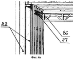
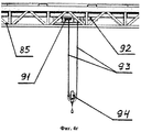
В многофункциональном учебно-тренировочном комплексе (по 1-му и 2-му варианту) как первое, так и второе механическое передаточное устройство включает опорную конструкцию прямоугольной формы, образованную комплектом вертикальных стоек, горизонтальных ферм и горизонтальных балок, подвижный мост, перемещающийся на колесах по рельсам, закрепленным на вертикальных стойках опорной конструкции, с помощью 2-х двигателей комплектного электропривода перемещения моста, подвижную тележку, перемещающуюся на колесах по рельсам, закрепленным на подвижном мосту, с помощью 4-х двигателей комплектного электропривода перемещения тележки, причем на подвижной тележке установлена лебедка, барабан которой, приводимый в движение двигателем комплектного электропривода вертикального перемещения, перемещает трос с блоком.In a multifunctional training complex (according to the 1st and 2nd options), both the first and second mechanical transmission devices include a rectangular support structure formed by a set of vertical posts, horizontal trusses and horizontal beams, a movable bridge moving on wheels along rails mounted on vertical racks of the supporting structure, using 2 engines of a complete electric drive to move the bridge, a movable trolley moving on wheels along rails fixed to the base to the main bridge, using 4 engines of a complete electric drive for moving the trolley, and a winch is installed on the movable trolley, the drum of which, driven by the engine of the complete electric drive for vertical movement, moves the cable with the block.
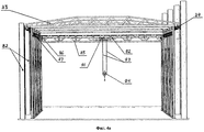
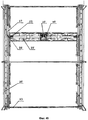
Помимо этого, в многофункциональном учебно-тренировочном комплексе (по 1-му и 2-му варианту) полномасштабный макет орбитального модуля МКС включает во внутреннем объеме оборудование комплекса средств шлюзования переходного и стыковочного отсеков (в том числе, выходной люк), а также оборудование, навесные механизмы и приборы, поручни и средства фиксации на внешней поверхности орбитального модуля, причем в верхней части по продольной оси корпуса полномасштабного макета орбитального модуля МКС, включая обрамление выходного люка, выполнен вырез, позволяющий перемещаться скафандру с обучаемым на подвесе и со шлангом обеспечения жизнедеятельности как во внутреннем объеме макета, так и в процессе перехода из внутреннего объема через выходной люк на внешнюю поверхность макета («выход в открытый космос»).In addition, in the multifunctional training complex (according to the 1st and 2nd options), the full-scale model of the ISS orbital module includes, in the internal volume, the equipment of the complex of means for locking the transition and docking compartments (including the exit hatch), as well as equipment, mounted mechanisms and devices, handrails and fixing means on the outer surface of the orbital module, and in the upper part along the longitudinal axis of the body of the full-scale prototype of the ISS orbital module, including the framing of the exit hatch, A cutaway that allows the spacesuit to move with the student on the suspension and with a life support hose both in the internal volume of the layout and in the process of transition from the internal volume through the exit hatch to the outer surface of the layout (“spacewalk”).
Сущность изобретения заключается в том, что в предлагаемом многофункциональном учебно-тренировочном комплексе, укрупнено состоящем из двух основных частей (функционально-моделирующего стенда предтренажерной подготовки и комплексного тренажера внекорабельной деятельности), обеспечивается эффективная подготовка к внекорабельной деятельности одновременно двух обучаемых космонавтов (астронавтов), «одетых» в штатный выходной скафандр Российского сегмента МКС типа «Орлан» и «погруженных» в интерактивное безопорное пространство с шестью степеням свободы в условиях имитируемой «полной» невесомости, по приобретению устойчивых перцептуальных (распознавательных) и сенсорно-моторных (исполнительных) навыков при отработке практических задач в открытом космическом пространстве на орбите Земли, а также обеспечивается подготовка обучаемых к предстоящим перспективным миссиям на поверхность космических объектов Солнечной системы, имеющим пониженную силу гравитацию. Кроме этого, в предлагаемом комплексе для одного из обучаемых космонавтов (астронавтов) предоставляется возможность практической подготовки к операциям по перемещению грузов на МКС с помощью действующего макета космического грузового манипулятора.The essence of the invention lies in the fact that in the proposed multifunctional training complex, enlarged consisting of two main parts (a functional-simulating stand for pre-training preparation and a complex simulator of extra-ship activity), effective preparation for extra-ship activity of simultaneously two trained astronauts (astronauts) is provided, " dressed "in a regular output spacesuit of the ISS Russian segment of the Orlan type and" immersed "in an interactive unsupported space with to three degrees of freedom under conditions of simulated “complete” weightlessness, to acquire stable perceptual (recognition) and sensory-motor (executive) skills when practicing practical tasks in open outer space in Earth’s orbit, as well as the training of students for upcoming promising missions to the surface of space objects of the solar system with reduced gravity. In addition, the proposed complex for one of the trained cosmonauts (astronauts) provides the opportunity for practical training for operations to move cargo to the ISS using the current prototype of the space cargo manipulator.
Сущность изобретения поясняется графическими материалами.The invention is illustrated graphic materials.
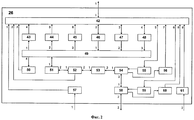
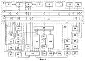
На фиг.1 представлена функционально-структурная схема многофункционального учебно-тренировочного комплекса для подготовки космонавтов (астронавтов) к внекорабельной деятельности (вариант 1 - режим «Совместная внекорабельная деятельность двух обучаемых»).Figure 1 presents the functional structural diagram of a multifunctional training complex for training astronauts (astronauts) for extra-ship activity (option 1 - mode "Joint extra-ship activity of two students").
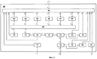
На фиг.2 представлена функционально-структурная схема первого электромеханического модуля обезвешивания с 6-ю степенями свободы.Figure 2 presents the functional structural diagram of the first electromechanical module weighing with 6 degrees of freedom.
На фиг.3 представлена функционально-структурная схема второго электромеханического модуля обезвешивания с 6-ю степенями свободы.Figure 3 presents the functional structural diagram of the second electromechanical module weighing with 6 degrees of freedom.
На фиг.4 представлена конструкция механического передаточного устройства с изображением ориентировочных мест установки отдельных компонентов электромеханического модуля обезвешивания (фиг.4а - вид спереди механического передаточного устройства в целом, фиг.4б - вид сверху механического передаточного устройства в целом, фиг.4в и 4б - виды отдельных фрагментов механического передаточного устройства).Figure 4 presents the design of the mechanical transmission device with the image of the approximate installation locations of the individual components of the electromechanical module of weightlessness (Fig.4a is a front view of the mechanical transmission device as a whole, Fig.4b is a top view of the mechanical transmission device as a whole, Fig.4b and 4b - types of individual fragments of a mechanical transmission device).
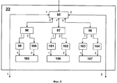
На фиг.5 представлена функционально-структурная схема системы визуализации.Figure 5 presents the functional structural diagram of the visualization system.
На фиг.6 представлена функционально-структурная схема многофункционального учебно-тренировочного комплекса для подготовки космонавтов (астронавтов) к внекорабельной деятельности (вариант 2 - режим «Работа обучаемого с космическим грузовым манипулятором»).Figure 6 presents the functional structural diagram of a multifunctional training complex for training astronauts (astronauts) for extra-ship activity (option 2 - mode "Work of the student with the space cargo manipulator").
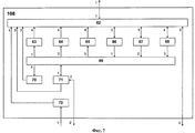
На фиг.7 представлена функционально-структурная схема электромеханического модуля обезвешивания с 3-мя степенями свободы.Figure 7 presents the functional structural diagram of the electromechanical module of weightlessness with 3 degrees of freedom.
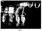
На фото 1 представлен общий вид специализированного тренажера «Выход-2» - это изображение принадлежит ФГБУ «НИИ ЦПК им. Ю.А. Гагарина», скопировано с Web-страницы: http://www.gctc.ru/main.php?id=145.
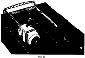
На фото 2 представлен общий вид космического грузового манипулятора типа «Стрела».On a
На рис.1а и 1б представлены синтезированные изображения общего вида многофункционального учебно-тренировочного комплекса с основным оборудованием в ракурсе 3/4 сверху.Figures 1a and 1b show synthesized images of a general view of a multifunctional training complex with basic equipment in a 3/4 view from above.
На рис.2 представлено синтезированное изображение вида сверху-сбоку полиэкранной стереопроекционной системы визуализации. Figure 2 shows a synthesized top-side view image of a multi-screen stereo projection visualization system.
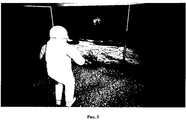
На рис.3 представлен обучаемый на участке, имитирующем поверхность Луны, и изображение, создаваемое системой визуализации.Figure 3 shows the student in the area simulating the surface of the moon, and the image created by the visualization system.
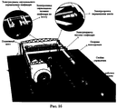
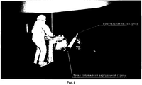
На рис.4 представлен обучаемый за пультом управления макетом космического грузового манипулятора в тренажном исполнении и изображение, синтезируемое системой визуализации.Figure 4 shows the student trained at the control panel for the mock-up of the space cargo manipulator and the image synthesized by the visualization system.
Согласно фиг.1, 2 и 3 многофункциональный учебно-тренировочный комплекс для подготовки космонавтов (астронавтов) к внекорабельной деятельности (вариант 1) включает:According to figures 1, 2 and 3, a multifunctional training complex for training astronauts (astronauts) for extra-ship activity (option 1) includes:
интегрирующую систему 1, состоящую из мобильного АРМ 2, адаптера беспроводной связи 3, сетевого сервера 4, консоли оператора 5, первого блока цифровой связи 6, многоканального видеорегистратора 7, локальной вычислительной сети передачи данных 8, локальной вычислительной сети видеонаблюдения и аудиопрослушивания 9 и локальной вычислительной сети цифровой связи 10;an integrating
«Гидролабораторию» 11 и «Молодежный образовательный Космоцентр» 12;“Hydrolaboratory” 11 and “Youth Educational Cosmocenter” 12;
функционально-моделирующий стенд предтренажерной подготовки 13, состоящий из АРМ руководителя обучения 14, АРМ обучаемых 15, первого блока устройств сопряжения с объектом 16, второго блока цифровой связи 17, действующего макета выходного космического скафандра 18, телекамеры наблюдения 19 и первого модуля средств отображения информации коллективного пользования 20;a functional-modeling stand for
комплект телекамер наблюдения 21, систему визуализации 22, первый 23 и второй 32 модули средств медицинского контроля, первый 24 и второй 31 скафандры, предназначенные для размещения обучаемых, сервер моделирования 25;a set of
первый электромеханический модуль обезвешивания с 6-ю степенями свободы 26, состоящий из первого комплекса устройств сопряжения с объектом 42, первого комплекта конечных выключателей 43, первого датчика положения моста 44, первого датчика положения тележки 45, первого комплектного электропривода перемещения моста 46, первого комплектного электропривода перемещения тележки 47, первого комплектного электропривода вертикального перемещения 48, первого механического передаточного устройства 49, первого датчика ускорений и угловых отклонений 50, первого упорного подшипника 51, первого демпфирующего устройства 53, первого одностепенного шарнирного подвеса для поворота по крену 54, первого комплектного электропривода перемещения по крену 55, первого датчика угла положения по крену 56, первого датчика положения обезвешиваемого объекта по вертикали 57, первого одностепенного шарнирного подвеса для поворота по тангажу 58, первого комплектного электропривода перемещения по тангажу 59, первого датчика угла положения по тангажу 60 и первого датчика угловых скоростей обезвешиваемого объекта 61;the first electromechanical weighing module with 6 degrees of
второй блок устройств сопряжения с объектом 27, модуль средств освещения 28, полномасштабный макет орбитального модуля МКС 29;the second block of devices for interfacing with the
второй электромеханический модуль обезвешивания с 6-ю степенями свободы 30, состоящий из второго комплекса устройств сопряжения с объектом 62, второго комплекта конечных выключателей 63, второго датчика положения моста 64, второго датчика положения тележки 65, второго комплектного электропривода перемещения моста 66, второго комплектного электропривода перемещения тележки 67, второго комплектного электропривода вертикального перемещения 68, второго механического передаточного устройства 69, второго датчика ускорений и угловых отклонений 70, второго упорного подшипника 71, второго датчика усилия 72, второго демпфирующего устройства 73, второго одностепенного шарнирного подвеса для поворота по крену 74, второго комплектного электропривода перемещения по крену 75, второго датчика угла положения по крену 76, второго датчика положения обезвешиваемого объекта по вертикали 77, второго одностепенного шарнирного подвеса для поворота по тангажу 78, второго комплектного электропривода перемещения по тангажу 79, второго датчика утла положения по тангажу 80 и второго датчика угловых скоростей обезвешиваемого объекта 81;a second electromechanical weightless module with 6 degrees of
пульт контроля и управления 33, состоящий из АРМ инженера 34. АРМ инструктора 35, третьего блока цифровой связи 35, АРМ врача 37, панели управления средствами обеспечения жизнедеятельности 38 и второго модуля средств отображения информации коллективного пользования 39;control and
средства обеспечения жизнедеятельности 40 и участок, имитирующий поверхность космического объекта Солнечной системы, с комплектом учебного оборудования 41.
К входу-выходу мобильного АРМ 2 через адаптер беспроводной связи 3 подключен первый вход-выход локальной вычислительной сети передачи данных 8.The input-output of the
К первому входу-выходу сетевого сервера 4 подключен второй вход-выход локальной вычислительной сети передачи данных 8, ко второму входу-выходу - первый вход-выход локальной вычислительной сети видеонаблюдения и аудиопрослушивания 9, к третьему входу-выходу - первый вход-выход локальной вычислительной сети цифровой связи 10 и к четвертому входу-выходу - вход-выход консоли оператора 5.The second input-output of the local area network of
К третьему входу-выходу локальной вычислительной сети передачи данных 8 подключен первый вход-выход АРМ обучаемых 15, к четвертому входу-выходу - первый вход-выход АРМ руководителя обучения 14, к пятому входу-выходу - первый вход-выход сервера моделирования 25, к шестому входу-выходу - первый вход-выход АРМ инженера 34, к седьмому входу-выходу - вход-выход АРМ инструктора 35, к восьмому входу-выходу - вход-выход АРМ врача 37, к первому входу - выход первого модуля средств медицинского контроля 23 и ко второму входу - выход второго модуля средств медицинского контроля 32.The first input-output of the
Ко второму входу-выходу локальной вычислительной сети видеонаблюдения и аудиопрослушивания 9 подключен вход-выход многоканального видеорегистратора 7, к третьему входу-выходу - вход-выход комплекта телекамер наблюдения 21, к четвертому входу-выходу - вход-выход телекамеры наблюдения 19, к пятому входу-выходу - второй вход-выход АРМ обучаемых 15, к шестому входу-выходу - второй вход-выход АРМ руководителя обучения 14, к седьмому входу-выходу - второй вход-выход АРМ инженера 34, к первому входу - второй выход первого скафандра, предназначенного для размещения обучаемого, 24, ко второму входу - третий выход второго скафандра, предназначенного для размещения обучаемого, 31, к третьему входу - выход «Гидролаборатории» 11 и к выходу - вход «Молодежного образовательного Космоцентра» 12.The second input-output of the local computer network of video surveillance and audio listening 9 is connected to the input-output of a
Ко второму входу-выходу локальной вычислительной сети цифровой связи 10 подключен вход-выход первого блока цифровой связи 6, к третьему входу-выходу - вход-выход второго блока цифровой связи 17, к четвертому входу-выходу - первый вход-выход первого скафандра, предназначенного для размещения обучаемого, 24, к пятому входу-выходу - второй вход-выход второго скафандра, предназначенного для размещения обучаемого, 31 и к шестому входу-выходу - вход-выход третьего блока цифровой связи 36.The input-output of the first
К третьему входу-выходу АРМ руководителя обучения 14 через первый блок устройств сопряжения с объектом 16 подключен вход-выход действующего макета выходного космического скафандра 18 и к выходу - вход первого модуля средств отображения информации коллективного пользования 20.To the third input-output of the workstation of the head of
К выходу сервера моделирования 25 подключен вход системы визуализации 22, ко второму входу-выходу - первый вход-выход электромеханического модуля обезвешивания с 6-ю степенями свободы 26, являющийся одновременно первым входом-выходом первого комплекса устройств сопряжения с объектом 42, к третьему входу-выходу - первый вход-выход второго блока устройств сопряжения с объектом 27 и к четвертому входу-выходу - первый вход-выход второго электромеханического модуля обезвешивания с 6-ю степенями свободы 30, являющийся одновременно первым входом-выходом второго комплекса устройств сопряжения с объектом 62.The output of the
К первому входу первого комплекса устройств сопряжения с объектом 42 первого электромеханического модуля обезвешивания с 6-ю степенями свободы 26 подключен выход первого датчика положения обезвешиваемого объекта по вертикали 57, ко второму входу - информационный выход первого датчика усилия 52, к третьему входу - выход первого датчика ускорений и угловых отклонений 50, к четвертому входу - выход первого комплекта конечных выключателей 43, к пятому входу - выход первого датчика положения моста 44, к шестому входу - выход первого датчика положения тележки 45, ко второму входу-выходу - вход-выход первого комплектного электропривода перемещения моста 46, к третьему входу-выходу - вход-выход первого комплектного электропривода перемещения тележки 47, к четвертому входу-выходу - вход-выход первого комплектного электропривода вертикального перемещения 48, к пятому входу-выходу - вход-выход первого комплектного электропривода перемещения по крену 55, к седьмому входу - выход первого датчика угла положения по крену 56, к шестому входу-выходу - вход-выход первого комплектного электропривода перемещения по тангажу 59, к восьмому входу - выход первого датчика угла положения по тангажу 60 и к девятому входу - выход первого датчика угловых скоростей обезвешиваемого объекта 61.The output of the first sensor of the position of the object to be weighted vertically 57 is connected to the first input of the first complex of devices for interfacing with the object 42 of the first electromechanical module of weightlessness with 6 degrees of freedom 26, the information output of the first force sensor 52 is connected to the second input, and the output of the first sensor is the third input accelerations and angular deviations 50, to the fourth input is the output of the first set of limit switches 43, to the fifth input is the output of the first bridge position sensor 44, to the sixth input is the output of the first position sensor 45, to the second input-output - the input-output of the first complete electric drive to move the bridge 46, to the third input-output - the input-output of the first complete electric drive to move the cart 47, to the fourth input-output - the input-output of the first complete vertical drive 48 , to the fifth input-output - the input-output of the first complete electric drive for moving along the roll 55, to the seventh input - the output of the first angle sensor for the roll 56, to the sixth input-output - the input-output of the first complete electric drive pitch pitch 59, the eighth input is the output of the first pitch angle sensor 60 and the ninth input is the output of the first angular velocity sensor of the weightless object 61.
К первому выходу первого механического передаточного устройства 49 первого электромеханического модуля обезвешивания с 6-ю степенями свободы 26 подключен вход первого комплекта конечных выключателей 43, ко второму выходу - вход первого датчика положения моста 44, к третьему выходу - вход первого датчика положения тележки 45, к первому входу - выход первого комплектного электропривода перемещения моста 46, ко второму входу - выход первого комплектного электропривода перемещения тележки 47, к третьему входу - выход первого комплектного электропривода вертикального перемещения 48, к четвертому выходу - вход первого датчика ускорений и угловых отклонений 50, к входу-выходу через последовательно соединенные первый упорный подшипник 51, первый датчик усилия 52, первое демпфирующее устройство 53 и первый одностепенной шарнирный подвес для поворота по крену 54 - вход-выход первого одностепенного шарнирного подвеса для поворота по тангажу 58.The input of the first set of
К входу первого одностепенного шарнирного подвеса для поворота по крену 54 первого электромеханического модуля обезвешивания с 6-ю степенями свободы 26 подключен выход первого комплектного электропривода перемещения по крену 55, к выходу - вход первого датчика угла положения по крену 56.The output of the first complete electric drive for moving along the
К входу первого одностепенного шарнирного подвеса для поворота тангажу 58 первого электромеханического модуля обезвешивания с 6-ю степенями свободы 26 подключен выход первого комплектного электропривода перемещения по тангажу 59, к выходу - вход первого датчика угла положения по тангажу 60.The output of the first complete electric drive to move the
К первому входу второго комплекса устройств сопряжения с объектом 62 второго электромеханического модуля обезвешивания с 6-ю степенями свободы 30 подключен выход второго датчика положения обезвешиваемого объекта по вертикали 77, ко второму входу - информационный выход второго датчика усилия 72, к третьему входу - выход второго датчика ускорений и угловых отклонений 70, к четвертому входу - выход второго комплекта конечных выключателей 63, к пятому входу - выход второго датчика положения моста 64, к шестому входу - выход второго датчика положения тележки 65, ко второму входу-выходу - вход-выход второго комплектного электропривода перемещения моста 66, к третьему входу-выходу - вход-выход второго комплектного электропривода перемещения тележки 67, к четвертому входу-выходу - вход-выход второго комплектного электропривода вертикального перемещения 68, к пятому входу-выходу - вход-выход второго комплектного электропривода перемещения по крену 75, к седьмому входу - выход второго датчика угла положения по крену 76, к шестому входу-выходу - вход-выход второго комплектного электропривода перемещения по тангажу 79, к восьмому входу - выход второго датчика угла положения по тангажу 80 и к девятому входу - выход второго датчика угловых скоростей обезвешиваемого объекта 81.The output of the second sensor of the position of the object to be deprived of weight from the vertical axis 77 is connected to the first input of the second complex of devices for interfacing with the object 62 of the second electromechanical module of weightlessness 30; the second input is the output of the second force sensor 72; the third input is the output of the second sensor accelerations and angular deviations of 70, to the fourth input is the output of the second set of limit switches 63, to the fifth input is the output of the second bridge position sensor 64, to the sixth input is the output of the second position sensor 65, to the second input-output - the input-output of the second complete electric drive to move the bridge 66, to the third input-output - the input-output of the second complete electric drive to move the truck 67, to the fourth input-output - the input-output of the second complete vertical drive 68 , to the fifth input-output - the input-output of the second complete electric drive for moving along the roll 75, to the seventh input - the output of the second angle sensor for the roll 76, to the sixth input-output - the input-output of the second complete electric drive pitch 79, to the eighth input is the output of the second pitch angle sensor 80 and to the ninth input is the output of the second angular velocity sensor of the weightless object 81.
К первому выходу второго механического передаточного устройства 69 второго электромеханического модуля обезвешивания с 6-ю степенями свободы 30 подключен вход второго комплекта конечных выключателей 63, ко второму выходу - вход второго датчика положения моста 64, к третьему выходу - вход второго датчика положения тележки 65, к первому входу - выход второго комплектного электропривода перемещения моста 66, ко второму входу - выход второго комплектного электропривода перемещения тележки 67, к третьему входу - выход второго комплектного электропривода вертикального перемещения 68, к четвертому выходу - вход второго датчика ускорений и угловых отклонений 70, к входу-выходу через последовательно соединенные второй упорный подшипник 71, второй датчик усилия 72, второе демпфирующее устройство 73 и второй одностепенный шарнирный подвес для поворота по крену 74 - вход-выход второго одностепенного шарнирного подвеса для поворота по тангажу 78.The input of the second set of
К входу второго одностепенного шарнирного подвеса для поворота по крену 74 второго электромеханического модуля обезвешивания с 6-ю степенями свободы 30 подключен выход второго комплектного электропривода перемещения по крену 75, к выходу - вход второго датчика угла положения по крену 76.The output of the second complete electric drive for moving along the roll 75 is connected to the input of the second single-stage articulated suspension for turning along the
К входу второго одностепенного шарнирного подвеса для поворота тангажу 78 второго электромеханического модуля обезвешивания с 6-ю степенями свободы 30 подключен выход второго комплектного электропривода перемещения по тангажу 79, к выходу - вход второго датчика угла положения по тангажу 80.The output of the second complete electric drive for
К первому выходу первого скафандра, предназначенного для размещения обучаемого 24, подключен вход первого модуля средств медицинского контроля 23, к третьему выходу - первый вход первого электромеханического модуля обезвешивания с 6-ю степенями свободы 26, являющийся одновременно входом первого датчика положения обезвешиваемого объекта по вертикали 57, ко второму входу-выходу - второй вход-выход первого электромеханического модуля обезвешивания с 6-ю степенями свободы 26, являющийся одновременно вторым входом-выходом первого одностепенного шарнирного подвеса для поворота по тангажу 58, к четвертому выходу - второй вход первого электромеханического модуля обезвешивания с 6-ю степенями свободы 26, являющийся одновременно входом первого датчика угловых скоростей обезвешиваемого объекта 61, к третьему входу-выходу - второй вход-выход системы визуализации 22, к четвертому входу-выходу - третий вход-выход средств обеспечения жизнедеятельности 40.The input of the first module of
Ко второму входу-выходу второго блока устройств сопряжения с объектом 27 подключен вход-выход полномасштабного макета орбитального модуля МКС 29, к третьему входу-выходу - вход модуля средств освещения 28.To the second input-output of the second block of devices pairing with the
К первому выходу второго скафандра, предназначенного для размещения обучаемого, 31 подключен первый вход второго электромеханического модуля обезвешивания с 6-ю степенями свободы 30, являющийся одновременно входом второго датчика положения обезвешиваемого объекта по вертикали 77, к первому входу-выходу - второй вход-выход второго электромеханического модуля обезвешивания с 6-ю степенями свободы 30, являющийся одновременно вторым входом-выходом второго одностепенного шарнирного подвеса для поворота по тангажу 78, ко второму выходу - второй вход второго электромеханического модуля обезвешивания с 6-ю степенями свободы 30, являющийся одновременно входом второго датчика угловых скоростей обезвешиваемого объекта 81, к четвертому выходу - вход второго модуля средств медицинского контроля 32, к третьему входу-выходу - первый вход-выход системы визуализации 22, к четвертому входу-выходу - второй вход-выход средств обеспечения жизнедеятельности 40.The first input of the second electromechanical weightless module with 6 degrees of
К первому входу-выходу средств обеспечения жизнедеятельности 40 подключен вход-выход панели управления средствами обеспечения жизнедеятельности 38 пульта контроля и управления 33.To the first input-output of
К выходу АРМ инженера 34 пульта контроля и управления 33 подключен вход второго модуля средств отображения информации коллективного пользования 39.The output of the engineer’s
Мобильный АРМ 2 интегрирующей системы 1 предназначен для оперативного управления оборудованием комплекса с произвольного места помещения, в котором установлен комплекс, например, управление в аварийных ситуациях электроприводами электромеханического модуля обезвешивания с 6-ю степенями свободы 26 (30), а также при выполнении пуско-наладочных работ и операций по техническому обслуживанию. В качестве мобильного АРМ 2 применен коммуникатор, имеющий возможность доступа к беспроводным сетям Wi-Fi по стандарту 802.11 (ноутбук, нетбук, планшетный компьютер, смартфон и т.д.).
В качестве адаптера беспроводной связи 3, предназначенного для создания беспроводных точек доступа к локальной вычислительной сети передачи данных 8, использован сетевой роутер беспроводной сети Wi-Fi по стандарту 802.11, например, типа «TRENDnet TEW-652BRP».As a
Сетевой сервер 4 представляют собой высокопроизводительный компьютер (с установленным программным обеспечением, соответствующим выполняемым функциональным задачам) в промышленном исполнении (в корпусе, предназначенном для установки в стойку с форм-фактором 19-дюймов). Основное назначение сетевого сервера 4 - обеспечение информационного обмена между локальными вычислительными сетями передачи данных 8, видеонаблюдения и аудиопрослушивания 9 и цифровой связи 10, а также оптимизация, при необходимости, протокола передачи информации по локальной вычислительной сети передачи данных 8 между средствами вычислительной техники, встроенными в основные составные части комплекса (АРМ руководителя обучения 14, АРМ обучаемых 15, первый 23 и второй 32 модуль средств медицинского контроля, сервер моделирования 25, АРМ инженера 34, АРМ инструктора 35 и АРМ врача 37). Кроме этого, сервер 4 обеспечивает организацию единой базы данных комплекса (например, для долговременного хранения информации по результатам учебно-тренировочного курса экипажа МКС, поступающей по локальной вычислительной сети передачи данных 8 от АРМ комплекса), а также коммутацию, трансляцию и запись (с возможностью последующего воспроизведения заинтересованными пользователями) речевых переговоров абонентов, циркулирующих по локальной вычислительной сети цифровой связи 10.
Консоль оператора 5, предназначенная для управления сетевым сервером 4, представляет собой комплект, состоящий из компьютерного LCD-монитора, клавиатуры и манипулятора «Мышь».The operator’s
Первый 6, второй 17 и третий 36 блоки цифровой связи, предназначенные для обеспечения оперативной связи эксплуатационного персонала (системный администратор интегрирующей системы 1, руководитель обучения в функционально-моделирующем стенде предтренажерной подготовки 13, инструктор, инженер и врач комплексного тренажера за пультом контроля и управления 33) в процессе обучения и ремонтно-технологической связи обслуживающего персонала при выполнении пуско-наладочных работ, операций по техническому обслуживанию и т.д., представляют собой компактные блоки с микротелефонной гарнитурой, которые позволяют осуществлять дуплексную телефонную цифровую связь по локальной вычислительной сети цифровой связи 10.The first 6, second 17, and third 36 digital communication units are designed to provide operational communications for operating personnel (the system administrator of the integrating
Многоканальный видеорегистратор 7, предназначенный для записи аудио-видеоинформации от выбранных телекамер наблюдения (телекамера наблюдения 19, телекамер наблюдения из комплекта 21, установленных в различных местах комплекса, и от телекамер, установленных на шлеме скафандров с обучаемыми 24 и 31), реализован на базе автономного регистратора с RAID-массивом на жестких магнитных дисках большого объема, например, типа «NV-2040 NUUO NVR mini».A
Локальные вычислительные сети передачи данных 8, видеонаблюдения и аудиопрослушивания 9 и цифровой связи 10 реализованы на базе высокоскоростных сетевых коммутаторов с интерфейсом «Ethernet» и кабелей связи типа «витая пара категории 6».Local area networks of
«Гидролаборатория» 11 (см. Web-страницу ФГБУ «НИИ ЦПК им. Ю.А. Гагарина»: http://www.gctc.ru/main.php?id=130) предназначена для проведения тренировок космонавтов в условиях моделируемой невесомости в гидросреде и обеспечивает решение задач: подготовки космонавтов для внекорабельной деятельности, выполнения экспериментальных исследований, проведения эргономических испытаний объектов космической техники и синхронного сопровождения работ, выполняемых космонавтами в открытом космосе.“Hydrolaboratory” 11 (see the web page of the FSBI “Research Institute of the CPC named after Yu.A. Gagarin”: http://www.gctc.ru/main.php?id=130) is intended for cosmonaut training in conditions of simulated weightlessness in the hydraulic environment and provides the solution of the following tasks: training of astronauts for extra-ship activity, carrying out experimental studies, conducting ergonomic tests of space technology objects and synchronous support of work performed by astronauts in outer space.
«Молодежный образовательный Космоцентр» 12 (см. Web-страницу: Космоцентр ФГБУ «НИИ ЦПК имени Ю.А. Гагарина», http://www.cosmocentr.ru/) предназначен для первоначальной общекосмической подготовки космонавтов и школьников с использованием современных информационно-телекоммуникационных образовательных технологий, в том числе технологии виртуальной реальности.“Youth Educational Cosmocenter” 12 (see Web page: Cosmocenter FSBI “Research Institute of the CPC named after Yu.A. Gagarin”, http://www.cosmocentr.ru/) is intended for initial general space training of cosmonauts and schoolchildren using modern information and telecommunication educational technologies, including virtual reality technology.
АРМ руководителя обучения 14 функционально-моделирующего стенда предтренажерной подготовки 13, АРМ инженера 34, инструктора 35 и врача 37 пульта контроля и управления 33, предназначенные для размещения одного специалиста за эргономичным компьютерным столом, реализованы на базе высокопроизводительного персонального компьютера с несколькими (от двух до четырех) компьютерных LCD-мониторов высокого разрешения, а также клавиатуры и манипулятора «Мышь».Workstation of the head of
АРМ обучаемых 15, предназначенные для размещения трех обучаемых за эргономичными компьютерными столами, реализованы на базе трех высокопроизводительных персональных компьютеров с двумя компьютерными LCD-мониторами высокого разрешения, а также клавиатуры и манипулятора «Мышь».
Первый блок устройств сопряжения с объектом 16 реализован на базе контроллера (с установленным программным обеспечением соответствующим выполняемым функциональным задачам) и набора модулей ввода-вывода дискретной и аналоговой информации (пример реализации - комплекс типа WP8841 из семейства «WinPack» тайваньской фирмы «ICP DAS»). Основное назначение первого блока 16 обеспечение функционирования оборудования действующего макета выходного космического скафандра 18.The first block of devices for interfacing with
Действующий макет выходного космического скафандра 18 предназначен для изучения устройства, конструкции, компоновки и работы основного оборудования штатных выходных скафандров Российского сегмента МКС для внекорабельной деятельности типа «Орлан», отработки операций по подготовке скафандра к использованию по прямому назначению и т.д.The current model of the
В качестве телекамеры наблюдения 19 и телекамер, входящих в комплект телекамер наблюдения 21, используются дистанционно управляемые (с возможность управления углом обзора, масштабированием и фокусировкой изображения) IP-камеры со встроенными микрофонами.As
В качестве первого модуля средств отображения информации коллективного пользования 20, предназначенного для демонстрации обучаемым функционально-моделирующего стенда предтренажерной подготовки 13 разнообразной учебной мультимедийной информации, использованы две большеразмерные LCD-панели высокого разрешения со встроенными акустическими системами.Two large-sized high-resolution LCD panels with built-in speaker systems were used as the first module of collective
Состав и устройство системы визуализации 22 представлены на фиг.5.The composition and structure of the
В качестве первого 23 и второго 32 модулей средств медицинского контроля, предназначенного для обеспечения оперативного контроля психофизиологического состояния обучаемого, находящегося в скафандре 24 (31), и передачи информации по локальной вычислительной сети передачи данных 8 на АРМ врача 37 на пульте контроля и управления 33, используется контроллер (с установленным программным обеспечением соответствующим выполняемым функциональным задачам) с устройствами преобразования, гальванической развязки и передачи медицинской информации.As the first 23 and second 32 modules of medical control devices, designed to provide operational monitoring of the psychophysiological state of a student located in a suit 24 (31), and transmit information through a local
В качестве скафандра 24 (31), предназначенного для размещения обучаемого, используются выходные космические скафандры, то есть скафандры, предназначенные для выхода космонавтов в открытый космос (штатные для Российского сегмента Международной космической станции) семейства «Орлан» (см. Материал из Википедии - свободной энциклопедии Орлан (скафандр), http://ru.wikipedia.org/wiki/Орлан_(скафандр). В комплексе использована специальная модификация скафандра в тренажном исполнении типа «Орлан-МКТ» с гибким шлангом обеспечения жизнедеятельности (подача воздуха для дыхания обучаемого и вентиляции внутреннего объема скафандра, низковольтного напряжения для электропитания разнообразного оборудования скафандра), свободно перемещающимся на специальных подвесах по тросу или рельсу (например, как показано на фото). В скафандре имеются комплекты средств связи, медицинской аппаратуры, оборудования обеспечения жизнедеятельности и IP-телекамера, установленная на шлеме скафандра, которые через шланг обеспечения жизнедеятельности подключаются соответственно к локальной вычислительной сети цифровой связи 10, модулю средств медицинского контроля 23 (32), средствам обеспечения жизнедеятельности 40 и локальной вычислительной сети видеонаблюдения и аудиопрослушивания 9. Кроме этого, для создания эффекта стереоизображения визуальной обстановки, обучаемый должен надеть стереоочки, которые через этот же шланг подключаются к системе визуализации 22. Для обеспечения жизнедеятельности и подключения оборудования скафандра вместо гибкого шланга можно использовать гибкие кабель-каналы серии «Sabin Chain» южно-корейской фирмы «CPS». Однако, гибкий шланг (или гибкий кабель-канал) обеспечения жизнедеятельности несколько ограничивает подвижность обучаемого в открытом пространстве (в частности, необходимо полностью исключить возможность перекручивания воздуховода в гибком шланге) и весьма значительно - во внутреннем объеме полномасштабного макета орбитального модуля МКС 29.As a spacesuit 24 (31), designed to accommodate the student, space shuttle suits are used, that is, spacesuits designed for astronauts to go into outer space (regular for the Russian segment of the International Space Station) of the Orlan family (see Material from Wikipedia - free Orlan Encyclopedia (space suit), http://ru.wikipedia.org/wiki/Orlan_ (space suit). The complex uses a special modification of the space suit in the training version of the Orlan-MKT type with a flexible life support hose (air supply the spirit for the student’s breathing and ventilation of the internal volume of the spacesuit, low-voltage voltage for powering various equipment of the spacesuit), freely moving on special suspensions along a cable or rail (for example, as shown in the photo). The spacesuit contains sets of communication equipment, medical equipment, and life support equipment and an IP camera mounted on the helmet of the spacesuit, which are connected through a life support hose to a
В качестве кардинального решения (с минимальными ограничениями подвижности обучаемого) вместо скафандра в тренажном исполнении типа «Орлан-МКТ» с гибким шлангом может быть использован скафандр в специальном исполнении, в котором установлены средства автономного жизнеобеспечения (аккумуляторная батарея, компрессор и преобразователь напряжений для электропитания разнообразного оборудования скафандра), позволяющие отказаться от шланга обеспечения жизнедеятельности. В этом случае средства связи, медицинская аппаратура, система управления средствами автономного жизнеобеспечения, IP-телекамера и стереоочки выполняются с возможностью беспроводного информационного обмена.As a cardinal solution (with minimal restrictions on the learner’s mobility), instead of the Orlan-MKT type exercise suit with a flexible hose, a special suit in which autonomous life support equipment is installed (battery, compressor and voltage converter for various power supplies) spacesuit equipment), allowing to abandon the hose for life support. In this case, communication equipment, medical equipment, an autonomous life support system, IP-camera and stereo glasses are made with the possibility of wireless information exchange.
Для исключения отдельных нежелательных воздействий (или хотя бы уменьшения последствий этих воздействий) на обучаемого в процессе его эволюций в электромеханическом модуле обезвешивания 26 (30), хотя и в безопорном пространстве с 6-ю степенями свободы, но в условиях Земного притяжения, предусмотрен ряд дополнений к конструкции скафандра, например мягкие ограничители для головы, исключающие резкое «наваливание» носом и лбом в остекление шлема скафандра, «подпорки» для ног, уменьшающие их провисание, при переходе обучаемого в горизонтальное положение (нулевой тангаж) и т.д.To exclude certain undesirable effects (or at least reduce the consequences of these effects) on the student during his evolution in the electromechanical module of weightlessness 26 (30), although in an unsupported space with 6 degrees of freedom, but under conditions of Earth's gravity, a number of additions are provided to the design of the spacesuit, for example, soft restraints for the head, eliminating the sharp "piling" of nose and forehead into the glazing of the helmet of the spacesuit, "support" for the legs, reducing their sagging, when the learner moves horizontally position (zero pitch), etc.
Сервер моделирования 25 представляют собой высокопроизводительный компьютер (с установленным программным обеспечением соответствующим выполняемым функциональным задачам) в промышленном исполнении (в корпусе, предназначенном для установки в стойку с форм-фактором 19-дюймов). Основное назначение сервера 25 - моделирование в Земных условиях среды, максимально приближенной к условиям отрытого космического пространства и перспективных для посещения космических объектов Солнечной системы, а также координация функционирования (в реальном масштабе времени) электромеханических модулей обезвешивания с 6-ю степенями свободы 24 и 30, системы визуализации 22 и средств освещения 28. Кроме этого, сервер 25 обеспечивает передачу необходимой информации в единую базу данных комплекса, реализованную в сетевом сервере 4.
Второй блок устройств сопряжения с объектом 27 реализован на базе контроллера (с установленным программным обеспечением соответствующим выполняемым функциональным задачам) и набора модулей ввода-вывода дискретной и аналоговой информации (пример реализации - комплекс типа WP8841 из семейства «WinPack» тайваньской фирмы «ICP DAS»). Основное назначение второго блока 27 - обеспечение функционирования оборудования модуля средств освещения 28 и полномасштабного макета орбитального модуля МКС 28.The second block of devices for interfacing with
Модуль средств освещения 28, предназначенный для моделирования светотеневой обстановки при работе обучаемого на внешней поверхности полномасштабного макета орбитального модуля МКС 29, а также на участке, имитирующем поверхность космического объекта Солнечной системы с комплектом учебного оборудования 41, реализован на базе нескольких прожекторов и устройств их включения и регулирования яркости.The lighting aids
Полномасштабный макет орбитального модуля МКС 29 предназначен для получения обучаемым космонавтом (астронавтом) сенсорно-моторных навыков внутри орбитального модуля при подготовке к выходу, при выполнении операций по непосредственному выходу в открытый космос, а также при работе на внешней поверхности макета в открытом космическом пространстве на орбите Земли. Макет 29 включает во внутреннем объеме оборудование комплекса средств шлюзования переходного и стыковочного отсеков (в том числе, выходной люк), штатное функционирование которых обеспечивается вторым блоком устройств сопряжения с объектом 27, а также оборудование, навесные механизмы и приборы, поручни и средства фиксации на внешней поверхности. В верхней части по продольной оси корпуса полномасштабного макета орбитального модуля МКС 29, включая обрамление выходного люка, выполнен вертикальный вырез, позволяющий перемещаться скафандру с обучаемым 24 (31) на подвесе и со шлангом обеспечения жизнедеятельности как во внутреннем объеме макета 29, так и в процессе перехода из внутреннего объема через выходной люк на внешнюю поверхность макета («выход в открытый космос»).The full-scale mock-up of the
Особенностью полномасштабного макета орбитального модуля МКС 29 является то, что он изготавливается на базе сборно-разборной каркасно-модульной конструкции с использованием способа создания полномасштабных (крупногабаритных) натурных макетов объектов аэрокосмической техники (см. Заявку ООО «Центра тренажеростроения» на получение патента РФ на изобретение №2012115841 от 19.04.2012).A feature of the full-scale prototype of the
Пульт контроля и управления 33, обеспечивающий размещение инструктора, инженера и врача комплекса за эргономичными автоматизированными рабочими местами, предназначен для задания сценария и начальных условий отработки практических задач внекорабельной деятельности, для экспериментальной отработки учебных упражнений с целью выбора наиболее эффективных методик реальной внекорабельной деятельности экипажей МКС и соответствующих им оптимальных методик подготовки космонавтов (астронавтов), для запуска и оперативного контроля процесса тренировки, ввода отказов, а также останова и завершения тренировки.The control and
Панель управления средствами обеспечения жизнедеятельности 38 предназначена для достоверного контроля состояния и оперативного управления средствами обеспечения жизнедеятельности 40 одновременно двух скафандров с обучаемыми 24 и 31.The vital
Второй модуль средств отображения информации коллективного пользования 39 предназначен для предъявления инструктору, инженеру и врачу аудиовизуальной обстановки в рабочих зонах комплексного тренажера, контролируемых комплектом телекамер наблюдения 21 и телекамерой, установленной на шлеме скафандра 24 (31), а также любой другой информации, формируемой серверами и компьютерами АРМ, например, формат инженера с изображением результатов контроля работоспособности программно-технических средств комплекса, которые задействуются в проводимом учебном мероприятии. В качестве второго модуля средств отображения информации коллективного пользования 39 использованы две большеразмерные LCD-панели высокого разрешения со встроенными акустическими системами.The second module of collective information display means 39 is intended for presentation to the instructor, engineer and doctor of the audiovisual situation in the working areas of the complex simulator, controlled by a set of
Средства обеспечения жизнедеятельности 40 предназначены для подачи воздуха для дыхания обучаемого и вентиляции внутреннего объема скафандра, а также электропитания оборудования, установленного в скафандре 24 (31).
Участок, имитирующий поверхность космического объекта Солнечной системы, с комплектом учебного оборудования 41 предназначен для отработки передвижения обучаемым космонавтом (астронавтом) в скафандре 24 (31) по различным рельефам, характерным, например, для поверхности Луны, крупных астероидов, Марса и т.д., перемещения (переноски) грузов, выполнения отдельных работ, технологических операций и т.д. в условиях имитируемой пониженной гравитации.A site simulating the surface of a space object in the solar system, with a set of
Первый 42 и второй 62 комплексы устройств сопряжения с объектом первого 26 и второго 30 электромеханического модуля обезвешивания с 6-ю степенями свободы, реализованы на базе контроллера (с установленным программным обеспечением соответствующим выполняемым функциональным задачам) и набора модулей ввода-вывода дискретной и аналоговой информации (пример реализации - комплекс типа WP8841 из семейства «WinPack» тайваньской фирмы «ICP DAS»). Основное назначение комплекса 42 (62) - управление (в реальном масштабе времени) электроприводами электромеханическго модуля обезвешивания с 6-ю степенями свободы, включая трансляцию, сформированных сервером моделирования 25, обобщенных управляющих воздействий на комплектные электроприводы перемещения моста 46 (66), тележки 47 (67) и вертикального перемещения 48 (68), а также получение контрольной информации от комплекта конечных выключателей 43 (63), от датчиков положения моста 44 (64), тележки 45 (65), датчиков ускорений и угловых отклонений 50 (70), усилия 52 (72), угла положения по крену 56 (76), положения обезвешиваемого объекта по вертикали 57 (77), угла положения по тангажу 60 (80) и угловых скоростей обезвешиваемого объекта 61 (81).The first 42 and second 62 complexes of devices for interfacing with the object of the first 26 and second 30 electromechanical modules of weightlessness with 6 degrees of freedom are implemented on the basis of the controller (with installed software appropriate to the functional tasks performed) and a set of input-output modules of discrete and analog information ( an example of implementation is a complex of type WP8841 from the WinPack family of Taiwanese company ICP DAS). The main purpose of complex 42 (62) is to control (in real time) the electric drives of the electromechanical weightless module with 6 degrees of freedom, including the translation generated by the
Первый 43 и второй 63 комплекты концевых выключателей предназначены для упреждающей остановки электродвигателей комплектных электроприводов горизонтального перемещения моста 46 (66), тележки 47 (67) и вертикального перемещения 48 (68), с целью предотвращения попадания подвижных элементов механического передаточного устройства 49 (69) в предельные положения, за которыми возможны их повреждения и поломки.The first 43 and second 63 sets of limit switches are designed to proactively stop the motors of the complete electric drives for horizontal movement of the bridge 46 (66), trolley 47 (67) and vertical movement 48 (68), in order to prevent the moving elements of the mechanical transmission device 49 (69) from getting into limit provisions beyond which damage and breakage are possible.
Первый 44 и второй 64 датчики положения моста, предназначенные для обеспечения контроля фактического положения моста (см. поз.85 на фиг.4) во всем диапазоне его линейного перемещения по рельсам (см. поз.87 на фиг.4), реализованы на основе электромагнитной головки (установлена на подвижном мосту 85), которая считывает магнитные метки положения с предварительно намагниченной ленты, закрепленной на неподвижной части опорной конструкции механического передаточного устройства 49 и 69 (например, на рельсе 87 - см. фиг.4). Пример реализации датчика положения моста 44 (64) - датчик типа «МТ H5-F1000-E-LD-MP500» итальянской фирмы «Givi Missure».The first 44 and second 64 position sensors of the bridge, designed to provide control of the actual position of the bridge (see pos. 85 in figure 4) in the entire range of its linear movement on rails (see pos. 87 in figure 4), are implemented on the basis of electromagnetic head (mounted on a movable bridge 85), which reads the magnetic position labels from a pre-magnetized tape mounted on the fixed part of the supporting structure of the
В качестве первого 45 и второго 65 датчиков положения тележки, предназначенных для обеспечения контроля фактического положения тележки (см. поз.89 на фиг.4) во всем диапазоне ее линейного перемещения по рельсам моста, используется датчик, аналогичный датчику положения моста 44 (64).As the first 45 and second 65 trolley position sensors designed to provide control of the actual position of the trolley (see pos. 89 in figure 4) in the entire range of its linear movement along the rails of the bridge, a sensor similar to the bridge position sensor 44 (64) is used .
Первый 46 и второй 66 комплектные электроприводы перемещения моста (линейная координата «x»), предназначенные для перемещения моста (см. поз.85 на фиг.4) механического передаточного устройства 49 (69), представляют собой функционально полный комплект, реализованный на основе серии сервоприводов «Dynamic Line II» немецкой фирмы «Karl E. Brinkmann GmbH» и состоящий из двух идентичных мотор-редукторов со встроенными дисковыми электромагнитными тормозами, двух частотных преобразователей напряжения, работающих синхронно, двух наборов датчиков напряжения, тока, положения ротора и температуры статора мотора. Причем в качестве моторов этого комплектного электропривода используются синхронные электродвигатели с постоянными магнитами в роторе.The first 46 and second 66 complete electric drives for moving the bridge (linear coordinate "x"), designed to move the bridge (see pos. 85 in figure 4) of the mechanical transmission device 49 (69), are a functionally complete set, implemented on the basis of the series servo drives “Dynamic Line II” of the German company “Karl E. Brinkmann GmbH” and consisting of two identical geared motors with built-in disk electromagnetic brakes, two frequency inverters operating synchronously, two sets of voltage, current, rotor position and stator temperature of the motor. Moreover, as the motors of this complete electric drive, synchronous motors with permanent magnets in the rotor are used.
Первый 47 и второй 67 комплектные электроприводы перемещения тележки (линейная координата «y»), предназначенные для перемещения тележки (см. поз.89 на фиг.4) механического передаточного устройства 49 (69), представляют собой функционально полный комплект, реализованный на основе серии сервоприводов «Dynamic Line II» немецкой фирмы «Karl E. Brinkmann GmbH» и состоящий из четырех идентичных мотор-редукторов со встроенными дисковыми электромагнитными тормозами, четырех частотных преобразователей напряжения, работающих синхронно, четырех наборов датчиков напряжения, тока, положения ротора и температуры статора мотора. Причем в качестве моторов этого комплектного электропривода используются синхронные электродвигатели с постоянными магнитами в роторе.The first 47 and second 67 complete electric drives for moving the cart (linear coordinate "y"), designed to move the cart (see pos. 89 in figure 4) of the mechanical transmission device 49 (69), are a functionally complete set, implemented on the basis of a series “Dynamic Line II” servomotors of the German company “Karl E. Brinkmann GmbH” and consisting of four identical geared motors with integrated disk electromagnetic brakes, four frequency inverters operating synchronously, four sets of voltage sensors voltage, current, rotor position and stator temperature of the motor. Moreover, as the motors of this complete electric drive, synchronous motors with permanent magnets in the rotor are used.
Первый 48 и второй 68 комплектные электроприводы вертикального перемещения (линейная координата «z»), предназначенные для перемещения блока (см. поз.94 на фиг.4) механического передаточного устройства 49 (69), представляют собой функционально полный комплект, реализованный на основе серии сервоприводов «Dynamic Line II» немецкой фирмы «Karl E. Brinkmann GmbH» и состоящий из мотор-редуктора с барабаном лебедки со встроенным дисковым электромагнитным тормозом, частотного преобразователя напряжения, набора датчиков напряжения, тока, положения ротора и температуры статора мотора. Причем в качестве мотора этого комплектного электропривода используется синхронный электродвигатель с постоянными магнитами в роторе.The first 48 and second 68 complete electric drives of vertical movement (linear coordinate "z"), designed to move the block (see pos. 94 in figure 4) of the mechanical transmission device 49 (69), are a functionally complete set, implemented on the basis of the series servo-drivers “Dynamic Line II” of the German company “Karl E. Brinkmann GmbH” and consisting of a geared motor with a winch drum with an integrated disc electromagnetic brake, a frequency inverter, a set of voltage, current, rotor and temperature sensors motor stator ry. Moreover, a synchronous electric motor with permanent magnets in the rotor is used as the motor of this complete electric drive.
Состав и устройство первого 49 и второго 69 механических передаточных устройств представлены на фиг.4а и 4б.The composition and device of the first 49 and second 69 mechanical transmission devices are presented in figa and 4b.
В качестве первого 50 и второго 70 датчиков ускорений и угловых отклонений, предназначенных для обеспечения контроля динамики движения и отклонения от вертикальной оси блока (см. поз.94 на фиг.4г) механического передаточного устройства 49 (69), применен акселерометр-инклинометр, например, из семейства «GNAMG» фирмы «Baumer IVO».As the first 50 and second 70 sensors of accelerations and angular deviations, designed to control the dynamics of movement and deviations from the vertical axis of the block (see pos. 94 in Fig. 4d) of the mechanical transmission device 49 (69), an accelerometer-inclinometer, for example , from the GNAMG family of Baumer IVO.
Первый 51 и второй 71 упорные подшипники предназначены для обеспечения поворотов скафандра с обучаемым 24 (31) вокруг вертикальной оси (перемещение по курсу - угловая координата «α»).The first 51 and second 71 thrust bearings are designed to provide turns of the spacesuit with the student 24 (31) around the vertical axis (moving along the course - angular coordinate "α").
В качестве первого 52 и второго 72 датчика усилия, предназначенного для обеспечения обратной связи по значению усилия обезвешивания при вертикальных перемещениях скафандра с обучаемым 24 (31), использован тензорезисторный датчик, например, типа U9B/5KN немецкой фирмы «Hottinger Baldwin Messtechnik GmbH».As the first 52 and second 72 force sensors, designed to provide feedback on the value of the weightless force during vertical movements of the suit with the student 24 (31), a strain gauge sensor, for example, type U9B / 5KN of the German company Hottinger Baldwin Messtechnik GmbH, was used.
В качестве первого 53 и второго 73 демпфирующего устройства, предназначенного для компенсации нежелательных динамических воздействий на обучаемого в скафандре 24 (31) при срабатывании электромагнитного тормоза комплектного электропривода вертикального перемещения 48 (68), используется специальный механизм рычажно-пружинной конструкции.As the first 53 and second 73 damping devices, designed to compensate for unwanted dynamic effects on the student in the suit 24 (31) when the electromagnetic brake of the complete vertical electric drive 48 (68) is activated, a special lever-spring mechanism is used.
Первый 54 и второй 74 одностепенные шарнирные подвесы для поворота по крену, предназначенные для обеспечения возможности поворота скафандра с обучаемым 24 (31) вокруг горизонтальной оси, проходящей через центр масс скафандра перпендикулярно передней/задней стороне скафандра (угловое перемещение по крену), представляют собой вертикальную штангу с зигзагообразным изгибом, в верхней части которого расположен узел крепления, а в нижней закреплен один поворотный шарнир консольного типа.The first 54 and second 74 single-hinged swivel suspensions for turning along the roll, designed to enable the student to rotate the spacesuit 24 (31) around a horizontal axis passing through the center of mass of the spacesuit perpendicular to the front / rear side of the spacesuit (angular movement along the roll), are vertical a rod with a zigzag bend, in the upper part of which there is a mounting unit, and in the lower one is fixed a swivel joint of the cantilever type.
Первый 55 и второй 75 комплектные электроприводы перемещения по крену (угловая координата «β»), предназначенные для перемещения скафандра в одностепенном шарнирном подвесе для поворота по крену 54 (74), представляют собой функционально полный комплект, реализованный на основе серии «IS23x Intelligent Step Motor Family» швейцарской фирмы «Technosoft S.A.» и состоящий из шагового двигателя, преобразователя напряжения, набора датчиков напряжения, тока, положения ротора и температуры статора двигателя.The first 55 and second 75 complete roll-type electric drives (angular coordinate "β"), designed to move the spacesuit in a single-stage hinged suspension for turning on roll 54 (74), are a functionally complete set, implemented on the basis of the IS23x Intelligent Step Motor series Family »of the Swiss company Technosoft SA and consisting of a stepper motor, a voltage converter, a set of sensors for voltage, current, rotor position and stator temperature of the motor.
В качестве первого 56 (60) и второго 76 (80) датчиков угла положения по крену и тангажу используется инкрементный угловой фотоэлектрический преобразователь перемещений, например датчик типа «ЛИР-158» «Специального Конструкторского Бюро Измерительных Систем».As the first 56 (60) and second 76 (80) roll angle and pitch angle sensors, an incremental angular photoelectric displacement transducer is used, for example, the LIR-158 type sensor of the Special Design Bureau of Measuring Systems.
В качестве первого 57 и второго 77 датчиков положения обезвешиваемого объекта по вертикали, предназначенного для обеспечения контроля фактического положения скафандра во всем диапазоне его перемещения по вертикали, используется трос-энкодер семейства «BTF» фирмы «SICK-Stegmann». Причем измерительный блок этого датчика установлен на подвижной тележке (см. поз.89 на фиг.4) механического передаточного устройства 49 (69), а конец тросика, вытягиваемого из измерительного блока датчика, зафиксирован на скафандре с обучаемым 24 (31).As the first 57 and second 77 sensors of the position of the weightless object vertically, designed to control the actual position of the spacesuit over the entire range of its vertical movement, the cable encoder family "BTF" from SICK-Stegmann is used. Moreover, the measuring unit of this sensor is mounted on a movable trolley (see pos. 89 in figure 4) of the mechanical transmission device 49 (69), and the end of the cable pulled from the measuring unit of the sensor is fixed on the suit with the student 24 (31).
Первый 58 и второй 78 одностепенные шарнирные подвесы для поворота по тангажу, предназначенные для обеспечения возможности поворота скафандра с обучаемым 24 (31) вокруг горизонтальной оси, проходящей через центр масс скафандра параллельно передней/задней стороне скафандра, представляют собой горизонтальную полуокружность (или полуовал), на средней части которого расположен узел крепления, а на концах закреплены два поворотных шарнира консольного типа.The first 58 and second 78 single-stage hinged pendants for turning along the pitch, designed to enable the suit with the student 24 (31) to rotate around a horizontal axis passing through the center of mass of the suit parallel to the front / back side of the suit, are a horizontal semicircle (or semi-circle), on the middle part of which there is a mounting unit, and at the ends two rotary hinges of the console type are fixed.
Первый 59 и второй 79 комплектные электроприводы перемещения по тангажу, предназначенные для перемещения скафандра в одностепенном шарнирном подвесе для поворота по тангажу 58 (78), представляют собой функционально полный комплект, реализованный на основе серии «IS23x Intelligent Step Motor Family» швейцарской фирмы «Technosoft S.A.» и состоящий из двух идентичных шаговых двигателей, двух преобразователей напряжения, двух наборов датчиков напряжения, тока, положения ротора и температуры статора двигателя.The first 59 and second 79 complete pitch movement electric drives designed to move the spacesuit in a single-stage articulated suspension for turning the pitch 58 (78) are a functionally complete set based on the IS23x Intelligent Step Motor Family series of the Swiss company Technosoft SA ”And consisting of two identical stepper motors, two voltage converters, two sets of sensors for voltage, current, rotor position and stator temperature of the motor.
В качестве первого 61 и второго 81 датчиков угловых скоростей обезвешиваемого объекта, предназначенного для определения (в любой текущий момент времени) динамики движения скафандра в системе трех угловых координат («α», «β» и «γ») моделируемого 6-степенного пространства, использован комплект микросхем со встроенными сенсорами, выполненных по технологии «MEMS» фирмы «InvenSense». Данный датчик закреплен в районе центра масс скафандра с обучаемым, а информация от него используется контроллером комплекса устройств сопряжения с объектом 42 (62) для замыкания обратной связи по скорости обезвешивания.As the first 61 and second 81 angular velocity sensors of a weightless object, designed to determine (at any current time) the dynamics of the spacesuit in the system of three angular coordinates ("α", "β" and "γ") of the simulated 6-degree space, a set of microcircuits with built-in sensors made according to the MEMS technology of InvenSense company was used. This sensor is fixed in the vicinity of the center of mass of the spacesuit with the student, and the information from it is used by the controller of the complex of devices for interfacing with object 42 (62) to close feedback on the rate of weightlessness.
Согласно фиг.4 первое механическое передаточное устройство (см. поз.49 на фиг.2) первого электромеханического модуля обезвешивания с 6-ю степенями свободы (см. поз.26 на фиг.1) включает опорную конструкцию прямоугольной формы, образованную комплектом вертикальных стоек 82, горизонтальных ферм 83 и горизонтальных балок 84 (в качестве опорной конструкции также можно использовать несущие стены помещения), подвижный мост 85, перемещающийся на колесах 86 по рельсам 87 (закреплены на вертикальных стойках 82 опорной конструкции) с помощью 2-х двигателей 88 комплектного электропривода перемещения моста (см. поз.46 на фиг.2), подвижную тележку 89, перемещающуюся на колесах (на фиг.4 не показаны) по рельсам (на фиг.4 не показаны), закрепленным на подвижном мосту 85, с помощью 4-х двигателей 90 комплектного электропривода перемещения тележки (см. поз.47 на фиг.2). На подвижной тележке 89 установлена лебедка 91, барабан которой, приводимый в движение двигателем 92 комплектного электропривода вертикального перемещения (см. поз.48 на фиг.2), перемещает трос 93 с блоком 94. На блоке 94 установлен датчик ускорений и угловых отклонений (на фиг.4 не показан, см. поз.50 на фиг.2).According to figure 4, the first mechanical transmission device (see pos. 49 in figure 2) of the first electromechanical module weighing with 6 degrees of freedom (see pos. 26 in figure 1) includes a rectangular support structure formed by a set of
Второе механическое передаточное устройство (см. поз.69 на фиг.3) второго электромеханического модуля обезвешивания с 6-ю степенями свободы (см. поз.30 на фиг.1) использует опорную конструкцию (стойки 82, фермы 83 и балки 84) и единые рельсы 87 первого механического передаточного устройства (см. поз.49 на фиг.2) первого электромеханического модуля обезвешивания с 6-ю степенями свободы (см. поз.26 на фиг.1), а в остальном - имеет абсолютно идентичный состав.The second mechanical transmission device (see pos. 69 in FIG. 3) of the second electromechanical de-weighting module with 6 degrees of freedom (see pos. 30 in FIG. 1) uses a support structure (struts 82,
К блоку 94 через последовательно соединенные упорный подшипник, датчик усилия, демпфирующее устройство, одностепенный шарнирный подвес для поворота по крену, одностепенный шарнирный подвес для поворота по тангажу подвешен скафандр с обучаемым (на фиг.4 не показаны). В качестве иллюстрации, на рис.1 представлены опорная конструкция, один из двух подвижных мостов с подвижной тележкой, тросом и блоком механического передаточного устройства, к которому на одностепенном шарнирном подвесе для поворота по тангажу подвешен скафандр с обучаемым.To the
В одностепенный шарнирный подвес для поворота по крену 54 (74) встроены комплектный электропривод поворота по крену 55 (75) и датчик угла положения по крену 56 (76), а в одностепенный шарнирный подвес для поворота по тангажу 58 (78) - комплектный электропривод поворота по тангажу 59 (79) и датчик угла положения по тангажу 60 (80) - на фиг.4 не показаны, см. фиг.2 и 3. Для исключения возможности переворота скафандра с обучаемым вниз головой в одностепенных шарнирных подвесах для поворота по крену 54 (74) и для поворота по тангажу 58 (78) использованы конечные выключатели и специальные упоры-ограничители.The one-stage articulated suspension for tilting the roll 54 (74) has a complete roll electric drive for tilting the roll 55 (75) and the angle sensor for the roll 56 (76), and the single-stage hinged suspension for turning the pitch 58 (78) has a complete electric rotary drive pitch 59 (79) and pitch angle sensor 60 (80) are not shown in FIG. 4, see FIGS. 2 and 3. To exclude the possibility of flipping a spacesuit with the learner upside down in single-stage articulated suspensions for turning along the roll 54 (74) and to turn the pitch 58 (78), the end switches and special and Limit Stops.
На скафандре с обучаемым зафиксирован конец тросика (на фиг.4 не показан), вытягиваемого из измерительного блока (на фиг.4 тоже не показан), который установлен на подвижной тележке 89, датчика положения обезвешиваемого объекта по вертикали (см. поз.57 и 77 на фиг.2 и 3).On the suit with the trainee, the end of the cable (not shown in Fig. 4), pulled out from the measuring unit (not shown in Fig. 4), which is mounted on a
Согласно фиг.5 система визуализации (см. поз.22 на фиг.1) включает сервер визуализации 95, первую 96, вторую 97 и третью 98 графические станции, а также первый 99, второй 100, третий 101, четвертый 102, пятый 103 и шестой 104 видеопроекторы, первый 105, второй 106 и третий 107 экраны (см. рис.2).According to figure 5, the visualization system (see pos.22 in figure 1) includes a
Вход, первый и второй вход-выход системы визуализации 22 являются одновременно соответственно входом, первым и вторым входом-выходом сервера визуализации 95; к третьему, четвертому и пятому входу-выходу сервера визуализации 95 подключены соответственно вход-выход первой 96, второй 97 и третьей 98 графических станций; первый выход первой графической станции 96 через первый видеопроектор 99 подключен к первому входу первого экрана 105, второй выход через второй видеопроектор 100 - ко второму входу первого экрана 105, первый выход второй графической станции 97 через третий видеопроектор 101 подключен к первому входу второго экрана 106, второй выход через четвертый видеопроектор 102 - ко второму входу второго экрана 106, первый выход третьей графической станции 98 через пятый видеопроектор 103 подключен к первому входу третьего экрана 107, второй выход через шестой видеопроектор 104 - ко второму входу третьего экрана 107.The input, the first and second input-output of the
Сервер визуализации 95 системы визуализации 22 представляет собой высокопроизводительный компьютер (с установленным программным обеспечением, соответствующим выполняемым функциональным задачам) в промышленном исполнении (в корпусе, предназначенном для установки в стойку с форм-фактором 19-дюймов). Основное назначение сервера визуализации 95 - координация функционирования графических станций 96, 97 и 97, обеспечивающая создание качественного слитного изображения (так называемая «сшивка» изображения на смежных сторонах экранов 105, 106 и 107).The
Кроме этого, так как система визуализации предназначена для генерации и воспроизведения стереоизображения, обучаемый в скафандре должен надеть стереоочки, состоящие из так называемого «трекера» (датчик положения и ориентации) и затворных экранов для левого и правого глаз. При этом сервер визуализации 95 осуществляет синхронизацию процесса воспроизведения изображений на экранах 105, 106 и 107 с управлением затворными экранами для левого и правого глаз стереоочков, обеспечивая обучаемому эффект стереоизображения визуальной обстановки, а также с помощью трекера стереоочков контролирует положение головы обучаемого в шлеме скафандра и направление его взгляда, что позволяет корректировать предъявляемое изображение с учетом изменяющейся так называемой «расчетной точки зрения». При отсутствии возможности у обучаемого использовать стереоочки сервер визуализации 95 переводит графические станции 96, 97 и 98 в режим работы только с первым 99, третьим 101 и пятым 103 видеопроекторами, которые проецируют на экраны 105, 106 и 107 единое изображение для левого и правого глаз обучаемого (изображение без стереоэффекта).In addition, since the visualization system is designed to generate and reproduce stereo images, a student in a spacesuit should wear stereo glasses consisting of a so-called “tracker” (position and orientation sensor) and shutter screens for the left and right eyes. At the same time, the
Первая 96, вторая 97 и третья 98 графические станции представляют собой высокопроизводительные компьютеры (с установленным программным обеспечением, соответствующим выполняемым функциональным задачам) в промышленном исполнении (в корпусе, предназначенном для установки в стойку с форм-фактором 19-дюймов).The first 96, second 97 and third 98 graphic stations are high-performance computers (with installed software that meets the functional tasks performed) in an industrial version (in a case designed for installation in a rack with a 19-inch form factor).
В качестве первого 99, второго 100, третьего 101, четвертого 102, пятого 103 и шестого 104 видеопроекторов использованы короткофокусные проекторы с высоким разрешением.High-resolution short-focus projectors were used as the first 99, second 100, third 101, fourth 102, fifth 103 and sixth 104 video projectors.
В качестве первого 105, второго 106 третьего 107 экранов предлагаемой полиэкранной системы визуализации использованы большеразмерные экраны просветного типа, обеспечивающие для обучаемого углы обзора по горизонтали 150…170° и по вертикали 70…80°. При необходимости визуализации окружающего пространства с большими углами обзора производится наращивание числа проекторов и экранов.As the first 105, second 106 of the third 107 screens of the proposed multi-screen visualization system, large-sized screens of the translucent type are used, providing for the student viewing angles horizontally 150 ... 170 ° and vertically 70 ... 80 °. If you need to visualize the surrounding space with large viewing angles, the number of projectors and screens is increased.
Как один из наиболее перспективных вариантов реализации, вместо использования видеопроекторов, большеразмерных экранов и стереоочков с затворными экранами, в составе системы визуализации 22 могут быть применены 3D видеоочки, например видеоочки дополненной реальности типа «Wrap 920AR» компании «Vuzix», которые не только отображают 3D графику, синтезированную высокопроизводительной графической станцией системы визуализации 22, но и имеют две внешние компактные видеокамеры, которые сканируют окружающую реальность в формате 3D и обеспечивают формирование интегрального изображения дополненной реальности (совмещение реального объемного мира с виртуальными 3D объектами) в 3D-стерео формате на микродисплеях видео-очков.As one of the most promising implementation options, instead of using video projectors, large-sized screens and stereo glasses with shutter screens, 3D video glasses can be used as part of the
Согласно фиг.6, 2 и 7 многофункциональный учебно-тренировочный комплекс для подготовки космонавтов (астронавтов) к внекорабельной деятельности (вариант 2) включает:According to Fig.6, 2 and 7, a multifunctional training complex for training astronauts (astronauts) for extra-ship activity (option 2) includes:
интегрирующую систему 1, состоящую из мобильного АРМ 2, адаптера беспроводной связи 3, сетевого сервера 4, консоли оператора 5, первого блока цифровой связи 6, многоканального видеорегистратора 7, локальной вычислительной сети передачи данных 8, локальной вычислительной сети видеонаблюдения и аудиопрослушивания 9 и локальной вычислительной сети цифровой связи 10;an integrating
«Гидролабораторию» 11 и «Молодежный образовательный Космоцентр» 12;“Hydrolaboratory” 11 and “Youth Educational Cosmocenter” 12;
функционально-моделирующий стенд предтренажерной подготовки 13, состоящий из АРМ руководителя обучения 14, АРМ обучаемых 15, первого блока устройств сопряжения с объектом 16, второго блока цифровой связи 17, действующего макета выходного космического скафандра 18, телекамеры наблюдения 19 и первого модуля средств отображения информации коллективного пользования 20;a functional-modeling stand for
комплект телекамер наблюдения 21, систему визуализации 22, модуль средств медицинского контроля 23, скафандр, предназначенный для размещения обучаемого, 24, сервер моделирования 25;a set of
электромеханический модуль обезвешивания с 6-ю степенями свободы 26, состоящий из первого комплекса устройств сопряжения с объектом 42, первого комплекта конечных выключателей 43, первого датчика положения моста 44, первого датчика положения тележки 45, первого комплектного электропривода перемещения моста 46, первого комплектного электропривода перемещения тележки 47, первого комплектного электропривода вертикального перемещения 48, первого механического передаточного устройства 49, первого датчика ускорений и угловых отклонений 50, первого упорного подшипника 51, первого датчика усилия 52, первого демпфирующего устройства 53, первого одностепенного шарнирного подвеса для поворота по крену 54, первого комплектного электропривода перемещения по крену 55, первого датчика угла положения по крену 56, первого датчика положения обезвешиваемого объекта по вертикали 57, первого одностепенного шарнирного подвеса для поворота по тангажу 58, первого комплектного электропривода перемещения по тангажу 59, первого датчика угла положения по тангажу 60 и первого датчика угловых скоростей обезвешиваемого объекта 61;electromechanical weightless module with 6 degrees of
второй блок устройств сопряжения с объектом 27, модуль средств освещения 28, полномасштабный макет орбитального модуля МКС 29;the second block of devices for interfacing with the
электромеханический модуль обезвешивания с 3-мя степенями свободы 108, состоящий из второго комплекса устройств сопряжения с объектом 62, второго комплекта конечных выключателей 63, второго датчика положения моста 64, второго датчика положения тележки 65, второго комплектного электропривода перемещения моста 66, второго комплектного электропривода перемещения тележки 67, второго комплектного электропривода вертикального перемещения 68, второго механического передаточного устройства 69, второго датчика ускорений и угловых отклонений 70, второго датчика усилия 71 и второго датчика положения обезвешиваемого объекта по вертикали 72;an electromechanical module of weightlessness with 3 degrees of
перемещаемый груз 109, космический грузовой манипулятор 110;transported
пульт контроля и управления 33, состоящий из АРМ инженера 34, АРМ инструктора 35, третьего блока цифровой связи 36, АРМ врача 37, панели управления средствами обеспечения жизнедеятельности 38 и второго модуля средств отображения информации коллективного пользования 39;control and
средства обеспечения жизнедеятельности 40 и участок, имитирующий поверхность космического объекта Солнечной системы, с комплектом учебного оборудования 41.
К входу-выходу мобильного АРМ 2 через адаптер беспроводной связи 3 подключен первый вход-выход локальной вычислительной сети передачи данных 8.The input-output of the
К первому входу-выходу сетевого сервера 4 подключен второй вход-выход локальной вычислительной сети передачи данных 8, ко второму входу-выходу - первый вход-выход локальной вычислительной сети видеонаблюдения и аудиопрослушивания 9, к третьему входу-выходу - первый вход-выход локальной вычислительной сети цифровой связи 10 и к четвертому входу-выходу - вход-выход консоли оператора 5.The second input-output of the local area network of
К третьему входу-выходу локальной вычислительной сети передачи данных 8 подключен первый вход-выход АРМ обучаемых 15, к четвертому входу-выходу - первый вход-выход АРМ руководителя обучения 14, к пятому входу-выходу - первый вход-выход сервера моделирования 25, к шестому входу-выходу - первый вход-выход АРМ инженера 34, к седьмому входу-выходу - вход-выход АРМ инструктора 5, к восьмому входу-выходу - вход-выход АРМ врача 37, к входу - выход модуля средств медицинского контроля 23.The first input-output of the
Ко второму входу-выходу локальной вычислительной сети видеонаблюдения и аудиопрослушивания 9 подключен вход-выход многоканального видеорегистратора 7, к третьему входу-выходу - вход-выход комплекта телекамер наблюдения 21, к четвертому входу-выходу - вход-выход телекамеры наблюдения 19, к пятому входу-выходу - второй вход-выход АРМ обучаемых 15, к шестому входу-выходу - второй вход-выход АРМ руководителя обучения 14, к седьмому входу-выходу - второй вход-выход АРМ инженера 34, к первому входу - второй выход скафандра, предназначенного для размещения обучаемого 24, ко второму входу - выход «Гидролаборатории» 211 и к выходу - вход «Молодежного образовательного Космоцентра» 12.The second input-output of the local computer network of video surveillance and audio listening 9 is connected to the input-output of a
Ко второму входу-выходу локальной вычислительной сети цифровой связи 10 подключен вход-выход первого блока цифровой связи 6, к третьему входу-выходу - вход-выход второго блока цифровой связи 17, к четвертому входу-выходу - первый вход-выход скафандра предназначенного для размещения обучаемого 24, к пятому входу-выходу - вход-выход третьего блока цифровой связи 36.The input-output of the first
К третьему входу-выходу АРМ руководителя обучения 14 через первый блок устройств сопряжения с объектом 16 подключен вход-выход действующего макета выходного космического скафандра 18 и к выходу - вход первого модуля средств отображения информации коллективного пользования 20.To the third input-output of the workstation of the head of
К выходу сервера моделирования 25 подключен вход системы визуализации 22, ко второму входу-выходу - первый вход-выход электромеханического модуля обезвешивания с 6-ю степенями свободы 26, являющийся одновременно первым входом-выходом первого комплекса устройств сопряжения с объектом 42, к третьему входу-выходу - первый вход-выход второго блока устройств сопряжения с объектом 27 и к четвертому входу-выходу - первый вход-выход электромеханического модуля обезвешивания с 3-мя степенями свободы 108, являющийся одновременно первым входом-выходом второго комплекса устройств сопряжения с объектом 42.The output of the
К первому входу первого комплекса устройств сопряжения с объектом 42 электромеханического модуля обезвешивания с 6-ю степенями свободы 26 подключен выход первого датчика положения обезвешиваемого объекта по вертикали 57, ко второму входу - информационный выход первого датчика усилия 52, к третьему входу - выход первого датчика ускорений и угловых отклонений 50, к четвертому входу - выход первого комплекта конечных выключателей 43, к пятому входу - выход первого датчика положения моста 44, к шестому входу - выход первого датчика положения тележки 45, ко второму входу-выходу - вход-выход первого комплектного электропривода перемещения моста 46, к третьему входу-выходу - вход-выход первого комплектного электропривода перемещения тележки 47, к четвертому входу-выходу - вход-выход первого комплектного электропривода вертикального перемещения 48, к пятому входу-выходу - вход-выход первого комплектного электропривода перемещения по крену 55, к седьмому входу - выход первого датчика угла положения по крену 56, к шестому входу-выходу - вход-выход первого комплектного электропривода перемещения по тангажу 59, к восьмому входу - выход первого датчика угла положения по тангажу 60 и к девятому входу - выход первого датчика угловых скоростей обезвешиваемого объекта 61.The output of the first sensor of the position of the object to be weighted vertically 57 is connected to the first input of the first complex of devices for interfacing with the object 42 of the electromechanical weightless module with 6 degrees of freedom 26, the information output of the first force sensor 52 is connected to the second input, and the output of the first acceleration sensor is to the third input and angular deviations 50, to the fourth input is the output of the first set of limit switches 43, to the fifth input is the output of the first bridge position sensor 44, to the sixth input is the output of the first trolley 4 position sensor 5, to the second input-output - the input-output of the first complete electric drive to move the bridge 46, to the third input-output - the input-output of the first complete electric drive to move the cart 47, to the fourth input-output - the input-output of the first complete vertical drive 48, to the fifth input-output - the input-output of the first complete roll movement electric drive 55, to the seventh input - the output of the first roll angle sensor 56, to the sixth input-output - the input-output of the first complete move electric drive p about pitch 59, to the eighth input is the output of the first pitch angle sensor 60 and to the ninth input is the output of the first angular velocity sensor of the weightless object 61.
К первому выходу первого механического передаточного устройства 49 электромеханического модуля обезвешивания с 6-ю степенями свободы 26 подключен вход первого комплекта конечных выключателей 43, ко второму выходу - вход первого датчика положения моста 44, к третьему выходу - вход первого датчика положения тележки 45, к первому входу - выход первого комплектного электропривода перемещения моста 46, ко второму входу - выход первого комплектного электропривода перемещения тележки 47, к третьему входу - выход первого комплектного электропривода вертикального перемещения 48, к четвертому выходу - вход первого датчика ускорений и угловых отклонений 50, к входу-выходу через последовательно соединенные первый упорный подшипник 51, первый датчик усилия 52, первое демпфирующее устройство 53 и первый одностепенной шарнирный подвес для поворота по крену 54 - вход-выход первого одностепенного шарнирного подвеса для поворота по тангажу 58.The input of the first set of
К входу первого одностепенного шарнирного подвеса для поворота по крену 54 электромеханического модуля обезвешивания с 6-ю степенями свободы 26 подключен выход первого комплектного электропривода перемещения по крену 55, к выходу - вход первого датчика угла положения по крену 56.The output of the first complete electric drive for moving along the
К входу первого одностепенного шарнирного подвеса для поворота тангажу 58 электромеханического модуля обезвешивания с 6-ю степенями свободы 26 подключен выход первого комплектного электропривода перемещения по тангажу 59, к выходу - вход первого датчика угла положения по тангажу 60.The output of the first complete electric drive to move the
К первому входу второго комплекса устройств сопряжения с объектом 62 электромеханического модуля обезвешивания с 3-мя степенями свободы 108 подключен выход второго датчика положения обезвешиваемого объекта по вертикали 72, ко второму входу - информационный выход второго датчика усилия 71, к третьему входу - выход второго датчика ускорений и угловых отклонений 70, к четвертому входу - выход второго комплекта конечных выключателей 63, к пятому входу - выход второго датчика положения моста 64, к шестому входу - выход второго датчика положения тележки 65, ко второму входу-выходу - вход-выход второго комплектного электропривода перемещения моста 66, к третьему входу-выходу - вход-выход второго комплектного электропривода перемещения тележки 67, к четвертому входу-выходу - вход-выход второго комплектного электропривода вертикального перемещения 68.The output of the second sensor of the position of the weighted object on the vertical 72 is connected to the first input of the second complex of devices for interfacing with the
К первому выходу второго механического передаточного устройства 69 электромеханического модуля обезвешивания с 3-мя степенями свободы 108 подключен вход второго комплекта конечных выключателей 63, ко второму выходу - вход второго датчика положения моста 64, к третьему выходу - вход второго датчика положения тележки 65, к первому входу - выход второго комплектного электропривода перемещения моста 66, ко второму входу - выход второго комплектного электропривода перемещения тележки 67, к третьему входу - выход второго комплектного электропривода вертикального перемещения 68, к четвертому выходу - вход второго датчика ускорений и угловых отклонений 70, к входу-выходу - второй датчик усилия 71.The input of the second set of
К первому выходу скафандра, предназначенного для размещения обучаемого, 24 подключен вход модуля средств медицинского контроля 23, к третьему выходу - первый вход первого электромеханического модуля обезвешивания с 6-ю степенями свободы 26, являющийся одновременно входом первого датчика положения обезвешиваемого объекта по вертикали 57, ко второму входу-выходу - второй вход-выход первого электромеханического модуля обезвешивания с 6-ю степенями свободы 26, являющийся одновременно вторым входом-выходом первого одностепенного шарнирного подвеса для поворота по тангажу 58, к четвертому выходу - второй вход первого электромеханического модуля обезвешивания с 6-ю степенями свободы 26, являющийся одновременно входом первого датчика угловых скоростей обезвешиваемого объекта 61, к третьему входу-выходу - вход-выход системы визуализации 22, к четвертому входу-выходу - второй вход-выход средств обеспечения жизнедеятельности 40.The input of the medical
Ко второму входу-выходу второго блока устройств сопряжения с объектом 27 подключен вход-выход полномасштабного макета орбитального модуля МКС 29, к третьему входу-выходу - вход модуля средств освещения 28.To the second input-output of the second block of devices pairing with the
К выходу перемещаемого груза 109 подключен вход электромеханического модуля обезвешивания с 3-мя степенями свободы 108, являющийся одновременно входом второго датчика положения обезвешиваемого объекта по вертикали 72, к первому входу-выходу - второй вход-выход электромеханического модуля обезвешивания с 3-мя степенями свободы 108, являющийся одновременно вторым входом-выходом второго датчика усилия 71, ко второму входу-выходу через космический грузовой манипулятор 110 - третий вход-выход электромеханического модуля обезвешивания с 3-мя степенями свободы 108, являющийся одновременно пятым входом-выходом второго комплекса устройств сопряжения с объектом 62.To the output of the transported
К первому входу-выходу средств обеспечения жизнедеятельности 40 подключен вход-выход панели управления средствами обеспечения жизнедеятельности 38 пульта контроля и управления 33.To the first input-output of
К выходу АРМ инженера 34 пульта контроля и управления 33 подключен вход второго модуля средств отображения информации коллективного пользования 39.The output of the engineer’s
В качестве перемещаемого груза 109 использован массогабаритный макет объекта, характерный для погрузочно-разгузочных операций, выполняемых на МКС (причем для учебно-тренировочных целей используется целый набор таких объектов).As the transported
Космической грузовой манипулятор 110, предназначенный для отработки операций в открытом космическом пространстве, связанных с перемещениями грузов и т.д., представляет собой действующий полномасштабный макет манипулятора «Стрела» (см. фото 2) и состоит из грузовой стрелы ГСтМ телескопической конструкции, такелажного узла на конце стрелы, приводного механизма (выдвижения-втягивания, перемещения вверх-вниз и влево-вправо) стрелы и поста оператора с пультом управления. На МКС манипулятор «Стрела» устанавливается на стыковочном отсеке - модуле СО-1 «Пирс» или на исследовательском модуле МИМ-2 «Поиск», а в предлагаемом комплексе космический грузовой манипулятор 232 - на полномасштабном макете (или фрагменте макета) орбитального модуля МКС 229. Как вариант реализации космического грузового манипулятора 232, в комплексе используется манипулятор «Стрела» в тренажном исполнении, состоящий только из поста оператора с пультом управления и части грузовой стрелы ГСтМ (например, только первого звена телескопической конструкции стрелы).The
Предлагаемый комплекс работает следующим образом.The proposed complex works as follows.
Многофункциональный учебно-тренировочный комплекс для подготовки космонавтов (астронавтов) к внекорабельной деятельности состоит из двух основных взаимодействующих частей: функционально-моделирующего стенда предтренажерной подготовки и комплексного тренажера внекорабельной деятельности. A multifunctional training complex for training cosmonauts (astronauts) for extra-ship activity consists of two main interacting parts: a functional-modeling pre-training training stand and a comprehensive extra-ship activity simulator.
Перед началом подготовки на комплексе обучаемые космонавты (астронавты) экипажей МКС и проходят соответствующую теоретическую подготовку. Кроме этого, для эффективного использования комплекса по прямому назначению производится тщательная методическая проработка содержания и последовательности учебных мероприятий.Before starting training at the complex, the trained cosmonauts (astronauts) of the ISS crews and undergo appropriate theoretical training. In addition, for the effective use of the complex for its intended purpose, a thorough methodological study of the content and sequence of training events is carried out.
В функционально-моделирующем стенде предтренажерной подготовки в соответствии с планом подготовки запускается сетевой сервер 4 интегрирующей системы 1, обучаемые космонавты (астронавтов) размещаются за АРМ обучаемых 15 функционально-моделирующего стенда предтренажерной подготовки 13, а руководитель обучения - за своим АРМ 14. Руководитель обучения по локальной вычислительной сети передачи данных 8 запрашивает у сетевого сервера 4 пакет информации, необходимой для проведения учебного мероприятия, а затем с помощью АРМ руководителя обучения 14 и первого модуля средств отображения информации коллективного пользования 20 предъявляет обучаемым учебный материал во всем необходимом многообразии: текст, речевая информация, 20-графика, видео с аудиосопровождением, вовлекая обучаемых в так называемый интерактивный учебный процесс, заключающийся в активном взаимодействии обучаемых с изучаемой предметной областью путем ритмичного чередования (по заранее подготовленному сценарию) выдачи модулей (порций) учебной информации и ожидании ответных реакции (конкретных ответных действий) на эту информацию от обучаемых, в том числе путем организации оперативных опросов, а также проведения автоматизированного тестирования. Причем наличие действующего макета выходного космического скафандра 18 позволяет произвести детально изучение устройства, конструкции и компоновки штатных выходных скафандров Российского сегмента МКС для внекорабельной деятельности типа «Орлан», а также практически и на высоком уровне отработать процедуры подготовки скафандра к использованию.In accordance with the preparation plan, the
При этом руководитель обучения имеет возможность предъявить обучаемым аудио-видеоинформацию (связанную с решением задач внекорабельной деятельности) при проведении тренировок других групп космонавтов в «Гидролаборатории» и на комплексном тренажере внекорабельной деятельности (предлагаемого комплекса), а также с помощью второго блока цифровой связи 17 вести переговоры с другими абонентами локальной вычислительной сети цифровой связи 10, причем ход учебного процесса может контролироваться заинтересованными пользователями по сети видеонаблюдения и аудиопрослушивания 9 с помощью телекамеры наблюдения 19. Конкретные результаты проведенного учебного мероприятия, например результаты автоматизированного тестирования обучаемых космонавтов по теме, изученной в данном учебном мероприятии, пересылаются на долговременное хранение в сетевой сервер 4.At the same time, the head of training has the opportunity to present trainees with audio-video information (related to solving tasks of extra-ship activity) during training of other groups of astronauts in the Hydrolaboratory and on the complex simulator of extra-ship activity (of the proposed complex), as well as using the second
После успешного завершения предтренажерной подготовки обучаемые космонавты переходят в помещение, в котором смонтировано оборудование комплексного тренажера внекорабельной деятельности многофункционального учебно-тренировочного комплекса. В качестве иллюстрации, на рис.1 представлены опорная конструкция, один из двух подвижных мостов с подвижной тележкой и подвешенным скафандром, полномасштабный макет орбитального модуля МКС, две стойки со средствами вычислительной техники (серверы, графические станции и т.д.) и пульт контроля и управления. Здесь обучаемые космонавты имеют возможность детально ознакомиться с устройством и конструкцией оборудования системы шлюзования, интерьером внутреннего объема переходного и стыковочного отсеков, выходного люка; с конструкцией оборудования, навесных механизмов и приборов, поручней и средств фиксации на внешней поверхности полномасштабного макета орбитального модуля МКС 29; с участком, имитирующим поверхность космического объекта Солнечной системы, и с комплектом учебного оборудования 41 (на рис.1 не показано), а также уточнить особенности Российского выходного скафандра типа «Орлан» и проверить готовность скафандров к использованию.After the successful completion of pre-training training, the trained cosmonauts move to the room in which the equipment of the complex simulator for extra-ship activity of the multifunctional training complex is mounted. As an illustration, Fig. 1 shows the support structure, one of two movable bridges with a moving trolley and a suspended suit, a full-scale model of the ISS orbital module, two racks with computer equipment (servers, graphic stations, etc.) and a control panel and management. Here, the trained cosmonauts have the opportunity to familiarize themselves in detail with the device and the design of the equipment of the locking system, the interior of the internal volume of the transition and docking compartments, the exit hatch; with the design of equipment, mounted mechanisms and devices, handrails and means of fixation on the outer surface of the full-scale prototype of the
После подачи электропитания обслуживающий персонал производит включение и проверку работоспособности оборудования (конкретный состав используемого оборудования определяется в соответствии с планом тренировки), устанавливает первый 24 и второй 31 скафандры на пол помещения комплексного тренажера в вертикальном положении, а инструктор, инженер и врач комплекса размещаются за пультом контроля и управления 33. После включения в работу средств обеспечения жизнедеятельности 40, обучаемые космонавты могут осуществить процесс одевания (или точнее «входа») скафандров с последующим запуском первого 23 и второго 32 модулей средств медицинского контроля. В процессе выполнения работ по проверке работоспособности обслуживающим персоналом используются первый 6 и третий 35 блоки цифровой связи, а также, при необходимости, мобильный АРМ 2.After the power supply is supplied, maintenance personnel turn on and check the equipment’s performance (the specific composition of the equipment used is determined in accordance with the training plan), installs the first 24 and second 31 spacesuits on the floor of the complex simulator in an upright position, and the instructor, engineer and doctor of the complex are placed at the console control and
Ввод начальных условий и запуск тренажера в работу.Entering initial conditions and starting the simulator in work.
Инструктор, выбрав с помощью программного обеспечения АРМ инструктора 35 на пульте контроля и управления 33 предусмотренный планом сценарий тренировки и соответствующий набор начальных условий (вариант видеопотока, генерируемого системой визуализации 22, исходное положение скафандров 24 (31), режим освещения и т.д.), запускает тренажер в работу.The instructor, using the
Внекорабельная деятельность в интерактивном безопорном пространстве (использование предлагаемого технического решения по варианту 1)Extra-ship activity in an interactive unsupported space (using the proposed technical solution for option 1)
Внекорабельная деятельность в открытом космическом пространстве осуществляется, как правило, одновременно двумя взаимодействующими космонавтами (астронавтами).Extra-ship activity in open space is carried out, as a rule, simultaneously by two interacting astronauts (astronauts).
Параметры набора начальных условий тренировки из АРМ инструктора 35 с помощью локальной вычислительной сети передачи данных 8 поступают в сервер моделирования 25. При этом в сервере моделирования 25 активируется программный модуль, обеспечивающий моделирование невесомости, который формирует соответствующие управляющие команды для сервера визуализации 95 системы визуализации 22, первого 42 и второго 62 контроллеров комплекса устройств сопряжения с объектом соответственно первого 26 и второго 30 электромеханических модулей обезвешивания с 6-ю степенями свободы и контроллера второго блока устройств сопряжения с объектом 27.The parameters of the set of initial training conditions from the
Система визуализации 22 формирует на экранах необходимое изображение окружающего космического пространства (звезды, орбитальные модули МКС и т.д.), которое с помощью видеопроекторов 99-104 проецируется на экраны 105-107. Одновременно с этим контроллеры, используя модули ввода-вывода дискретной и аналоговой информации комплекса устройств сопряжения с объектом 42 (62), с помощью комплектных электроприводов вертикального перемещения 48 (68), перемещения моста 46 (66) и перемещения тележки 47 (67) осуществляют позиционирование скафандров с обучаемыми 24 и 31 в требуемой зоне помещения тренажера, контролируя правильность отработки своих управляющих воздействий с помощью датчика положения обезвешиваемого объекта по вертикали 57 (77), датчиков положения тележки 44 (64) и моста 45 (65). После отработки заданных линейных координат схемы автоматики комплектных электроприводов останавливают электродвигатели, синхронно включая электромагнитные тормоза, которые надежно фиксируют скафандры с обучаемыми 24 и 31 по вертикали и в горизонтальной плоскости. Для повышения эффективности компенсации нежелательных (в том числе и опасных) динамических воздействий на обучаемого в скафандре при его вертикальных перемещениях и в особенности при аварийном срабатывании электромагнитного тормоза комплектного электропривода вертикального перемещения 48 (68) в тренажере использовано демпфирующее устройство 53 (73). В это же время контроллер второго блока устройств сопряжения с объектом 27, используя модули ввода-вывода дискретной и аналоговой информации, создает необходимый режим освещения рабочей зоны тренажера.The
При необходимости перемещения в безопорном пространстве тренажера, обучаемый, например, отталкивается руками от элементов конструкции полномасштабного макета орбитального модуля МКС 29 (или, захватив элементы конструкции, притягивает их к себе руками). Создаваемые обучаемым усилия, в общем случае, состоят из трех составляющих векторов (усилие по вертикали и два взаимно перпендикулярных усилия в горизонтальной плоскости) и трех моментов (момент по курсу, крену и тангажу). Данные усилия вызывают пропорциональное их величине изменение значения выходного сигнала датчика усилия 52 (72), датчика ускорений и угловых отклонений 50 (70) и датчика угловых скоростей обезвешиваемого объекта 61 (81), которые поступают в контроллер комплекса устройств сопряжения с объектом 42 (62). Программное обеспечение этого контроллера выполняет решение уравнений динамики и формирует управляющие воздействия для комплектного электропривода вертикального перемещения 48 (68), перемещения моста 46 (66), перемещения тележки 47 (87), перемещения по крену 55 (75) и перемещения по тангажу 59 (79), что приводит к соответствующему (в зависимости от величины и продолжительности усилия, прилагаемого обучаемым) перемещению скафандра с обучаемым в направлении, противоположном направлению прилагаемого усилия.If it is necessary to move in the unsupported space of the simulator, the student, for example, pushes away from the structural elements of the full-scale model of the
Таким образом, в интерактивном безопорном пространстве, создаваемом функционально-моделирующим стендом, осуществляется активное силокомпенсирующее обезвешивание с помощью управляемых электроприводов по вертикали и в горизонтальной плоскости, а также при повороте по крену и тангажу. А момент, создаваемый обучаемым по курсу, благодаря использованию в подвеске скафандра с обучаемым 24 и 31 упорного подшипника 51 (71), приводит к соответствующему повороту скафандра за счет мускульной силы обучаемого также в направлении, противоположном направлению прилагаемого усилия.Thus, in the interactive unsupported space created by the functional-modeling stand, active power-compensating weightlessness is carried out using controlled electric drives vertically and horizontally, as well as when turning along the roll and pitch. And the moment created by the trainee on the course, due to the use of the suspension suit with the
Для исключения возможности перекручивания шланга средств обеспечения жизнедеятельности 40 угол поворота обучаемого в скафандре 24 и 31 ограничен (предельные значения не более 180° как против часовой стрелки, так и по часовой стрелке) конструкцией упорного подшипника 51 (71). Помимо этого осуществляется контроль текущего угла поворота (то есть угла положения обучаемого в скафандре по курсу) как в автоматическом режиме программным обеспечением сервера моделирования 25 по значениям, получаемым от датчика угловых скоростей обезвешиваемого объекта 61 (с выдачей соответствующей предупредительной информации, например, на АРМ врача 37 пульта контроля и управления 33 или на второй модуль средства отображения информации коллективного пользования 39, так и непосредственно врачом тренажера при визуальном наблюдении за действиями обучаемых с помощью комплекта телекамер наблюдения 21.To exclude the possibility of twisting the hose of
При отработке отдельных учебных упражнений, для которых характерны динамичные воздействия обучаемого, для уменьшения времени реакции контроллера комплекса устройств сопряжения с объектом 42 (62) по управлению интерактивным безопорным пространством предусмотрена реализация части задач по упрощенному алгоритму.When practicing individual training exercises, which are characterized by dynamic effects of the learner, to reduce the reaction time of the controller of the complex of devices for interfacing with the object 42 (62) for managing interactive unsupported space, part of the tasks are implemented according to a simplified algorithm.
При отработке задач внекорабельной деятельности во внутреннем объеме полномасштабного макета орбитального модуля МКС 29 обучаемый, выполнив требуемые операции в соответствии с циклограммами шлюзования, открывает выходной люк и, приняв положение по тангажу близкое к горизонтальному (нулевой тангаж), осуществляет «выход в открытый космос».When practicing the tasks of extra-ship activity in the internal volume of the full-scale prototype of the
Далее с помощью поручней обучаемый перемещается по внешней поверхности полномасштабного макета орбитального модуля МКС 29 фиксируется страховочным фалом скафандра в нужной для выполнения работы зоне макета и выполняет необходимые операции с оборудованием, навесными механизмами и приборами, установленными в рабочей зоне на внешней поверхности макета. Причем для воссоздания яркого солнечного освещения макета, требующего от обучаемого, например, использования светофильтра на шлеме скафандра, инструктор на пульте контроля и управления 33 (с помощью соответствующего программного обеспечения АРМ инструктора 35) имеет возможность регулирования яркости прожекторов из состава модуля средств освещения 28.Then, with the help of handrails, the student moves along the outer surface of the full-scale prototype of the
В процессе тренировки средства обеспечения жизнедеятельности 40 осуществляют очистку и подачу воздуха для дыхания обучаемого и вентиляции внутреннего объема скафандра, а также подачу низковольтного напряжения для электропитания устройств оборудования скафандра с обучаемым 24 и 31. Кроме этого, с помощью средств обеспечения жизнедеятельности 40 имеется возможность изменять (в определенном интервале) давление воздуха внутри скафандра, изменяя скафандр от сжатого до максимально раздутого состояния, движение в котором требует от обучаемого максимальных мышечных усилий.In the process of training,
Обучаемый с помощью комплекта средств связи скафандра 24 и 31, подключенных к локальной вычислительной сети цифровой связи 10, имеет возможность вести речевой обмен с инструктором (врачом) стенда, которые в процессе тренировки выполняют роль как специалистов Центра управления полетами, так и других членов экипажа МКС, находящихся внутри орбитальных модулей.Trained using a set of communication equipment of a
В процессе тренировки с помощью датчиков, закрепленных на теле обучаемого, и комплекта медицинской аппаратуры скафандра снимаются сигналы электрокардиограммы, пневмограммы и значения температуры тела, которые через первый 23 и второй 32 модуль средств медицинского контроля поступают в АРМ врача 37 пульта контроля и управления 33, позволяя врачу комплексного тренажера осуществлять в реальном масштабе времени достоверный контроль психофизиологического состояния обучаемых.In the process of training, with the help of sensors mounted on the student’s body and a set of medical equipment of the spacesuit, the signals of the electrocardiogram, pneumograms and body temperature are taken, which through the first 23 and second 32 module of the medical control device enter the doctor’s
За отработкой процедур и упражнений по внекорабельной деятельности обучаемого в процессе тренировки, инструктором и врачом осуществляется дистанционное визуальное наблюдение с помощью комплекта телекамер наблюдения 21. Кроме этого, телекамера, установленная на шлеме скафандра 24 и 31, предоставляет инструктору дополнительную возможность наблюдения за действиями обучаемого непосредственно в его рабочей зоне, что позволяет значительно более объективно оценивать правильность выполнения конкретных операций и упражнений.The instructor and the doctor carry out remote visual monitoring of the procedures and exercises for extra-ship activity of the student during the training, using the set of
Работа в условиях пониженной гравитации (использование предлагаемого технического решения по варианту 1)Work in conditions of reduced gravity (using the proposed technical solution for option 1)
Как известно, внекорабельная деятельность в условиях пониженной гравитации на спутнике Земли Луне осуществлялась одновременно двумя взаимодействующими американскими астронавтами и, вероятно, также будет осуществляться, как минимум, двумя взаимодействующими космонавтами (астронавтами) и на других космических объектах Солнечной системы.As you know, extra-ship activity in conditions of reduced gravity on the Earth’s moon satellite was carried out simultaneously by two interacting American astronauts and is likely to also be carried out by at least two interacting astronauts (astronauts) and other space objects of the solar system.
Параметры набора начальных условий тренировки из АРМ инструктора 35 с помощью локальной вычислительной сети передачи данных 8 поступают в сервер моделирования 25. При этом в сервере моделирования 25 активируется программный модуль, обеспечивающий моделирование пониженной гравитации (0,165 от земной для Луны и 0,378 - для Марса и т.д.). Далее, система визуализации 22 синтезирует изображение, например, окружающего Лунного пейзажа (см. рис.3), электромеханические модули обезвешивания 26 (30) перемещают скафандры с обучаемыми 24 (31) на участок, имитирующий поверхность космического объекта Солнечной системы (в данном случае, Луны), с комплектом учебного оборудования 41 (на рис.3 не показано), а модуль средств освещения 28 создает необходимый режим освещения.The parameters of the set of initial training conditions from the
Обучаемый в скафандре 24 (31), стоя, например, на участке, имитирующей поверхность Луны, начинает движение. Анализ опыта работы американских астронавтов на Луне (см. Техническое предложение ООО «Центр тренажеростроения и подготовки персонала» ЦТКФ.161454.081 ПЗ Динамический стенд «Селен». Модернизация. Пояснительная записка, 2010 год) показал, что характерная для земных условий походка на Луне является неудобной. Так как используемый скафандр характеризуется тем, что помимо жесткой конструкции он имеет смещение центра тяжести вверх и несколько назад, то, чтобы не потерять равновесие в жестком скафандре астронавту при ходьбе необходимо существенно наклонятся вперед. Кроме этого, пониженное по сравнению с земным сцепление подошв обуви с лунным грунтом несколько снижает скорость движения астронавта на поворотах, однако, при приобретении им определенных навыков привычная скорость движения при поворотах все же достигается. В тренажере требуемые наклоны набок, вперед и повороты обучаемого в скафандре вокруг вертикальной оси обеспечиваются соответственно с помощью одностепенных шарнирных подвесов 54 (74) и 58 (78), а также упорного подшипника 51 (71).Trained in a spacesuit 24 (31), standing, for example, on a site that mimics the surface of the moon, begins to move. An analysis of the work experience of American astronauts on the Moon (see Technical Proposal of Center for Simulator Engineering and Personnel Training LLC TsTKF.161454.081 PZ Dynamic Selen Seat. Modernization. Explanatory note, 2010) showed that the moon trip characteristic of terrestrial conditions is inconvenient . Since the spacesuit used is characterized by the fact that in addition to the rigid structure it has a shift of the center of gravity upward and somewhat backwards, in order not to lose balance in the rigid spacesuit, the astronaut must substantially lean forward while walking. In addition, the grip of the soles of the shoes with the lunar soil, lower than that on the ground, somewhat reduces the astronaut's speed at bends, however, when he acquires certain skills, the usual speed at bends is still achieved. In the simulator, the required tilts to the side, forward, and turns of the student in the spacesuit around the vertical axis are provided, respectively, using single-stage hinged suspensions 54 (74) and 58 (78), as well as a thrust bearing 51 (71).
В комплексном тренажере при отработке передвижений по имитируемой поверхности Луны, обеспечивается активное силокомпенсирующее обезвешивание обучаемого в скафандре 24 (31) при перемещениях по вертикали (компенсация гравитационных сил Лунного притяжения), компенсация сил трения в механических передачах и инерции масс подвижных элементов в горизонтальной плоскости и при перемещениях по курсу и тангажу (три линейных и две угловых координаты), а также пассивная подвижность по курсу за счет мускульной силы, то есть принципиально - абсолютно аналогично работе обучаемого в условиях невесомости. Очевидно только, что при движении по имитируемой поверхности Луны обучаемый космонавт (астронавт) создает усилия, преимущественно, отталкивания, причем, в основном ногами, а моделируемые динамические характеристики перемещений в условиях имитируемых невесомости и пониженной гравитации Луны существенно отличаются.In the complex simulator, when practicing movements on the simulated surface of the Moon, active force-compensating de-weighting of the trainee in the spacesuit 24 (31) is provided when moving vertically (compensation of the gravitational forces of the Lunar attraction), compensation of friction forces in mechanical transmissions and mass inertia of the moving elements in the horizontal plane and at heading and pitch movements (three linear and two angular coordinates), as well as passive heading mobility due to muscular strength, that is, in principle - absolutely nalogichno the learner in conditions of weightlessness. It is obvious only that when moving along the simulated surface of the moon, the trained cosmonaut (astronaut) creates efforts, mainly repulsion, and, mainly, with his feet, and the simulated dynamic characteristics of movements in conditions of simulated weightlessness and reduced gravity of the moon are significantly different.
На тренажере помимо приобретения навыков хождения по имитируемой поверхности Луны предполагается также выполнять следующие экспериментальные исследования и учебные задачи: бег вприпрыжку и скачки по ровной (наклонной) как по твердой, так и по мягкой поверхности (песок, вязкий грунт и пыль) при отсутствии (при наличии) препятствий; падение вперед, назад, вправо или влево и подъем после этого на ноги; наклоны вперед и опускание на одно или оба колена и подъем после этого на ноги; спуск и подъем по трапу; перемещение (переноска) макетов различных приборов и оборудования, имеющихся в составе участка, имитирующего поверхность Луны, с комплектами учебного оборудования 41.On the simulator, in addition to acquiring walking skills on the simulated surface of the Moon, it is also planned to carry out the following experimental studies and training tasks: jogging and racing on a flat (inclined) surface both on hard and soft surfaces (sand, viscous soil and dust) in the absence of the presence of) obstacles; fall forward, backward, right or left and then rise to your feet; bending forward and lowering to one or both knees and lifting to feet afterwards; descent and ascent along the ladder; moving (carrying) layouts of various instruments and equipment available as part of a site simulating the surface of the Moon, with sets of
Работа с космическим грузовым манипулятором (использование предлагаемого технического решения по варианту 2)Work with a space cargo manipulator (using the proposed technical solution for option 2)
Актуальной особенностью предлагаемого тренажера является возможность отработки комплекса задач по использованию космического грузового манипулятора 231. Для реализации этой возможности один из обучаемых в скафандре 24 обезвешивается электромеханическим модулем обезвешивания с 6-ю степенями свободы 26, а на блок (см. поз.94 на фиг.4а) механического передаточного устройства 69, входящего в состав электромеханического модуля обезвешивания с 3-мя степенями свободы 108, подвешивается перемещаемый груз 109, с которым соединен такелажный узел на конце стрелы космического грузового манипулятора ПО. Обучаемый, переместившись по внешней поверхности полномасштабного макета орбитального модуля МКС 29, фиксирует скафандр 24 на посту оператора действующего полномасштабного макета манипулятора «Стрела» и, воздействуя на органы его пульта управления с целью изменения вылета (выдвижение-втягивание) и перемещения (вверх-вниз и влево-вправо) грузовой стрелы ГСтМ, создает соответствующие усилия на конце стрелы. Эти усилия, в общем случае, состоят из трех составляющих векторов (усилие по вертикали и два взаимно перпендикулярных усилия в горизонтальной плоскости), которые отрабатываются электромеханическим модулем обезвешивания с 3-мя степенями свободы 108, абсолютно аналогично усилиям, создаваемым обучаемым при перемещениях в безопорном пространстве тренажера с 3-мя линейными координатами.A relevant feature of the proposed simulator is the ability to work out a set of tasks for using a space cargo manipulator 231. To realize this possibility, one of the trainees in a
При использовании манипулятор «Стрела» в тренажном исполнении (состоящем только из поста оператора с пультом управления и части грузовой стрелы ГСтМ) при воздействии обучаемого на органы пульта управления происходит перемещение (вверх-вниз и влево-вправо) только первого реального звена телескопической конструкции грузовой стрелы ГСтМ, а контрольная информация о данных управляющих воздействиях через контроллер комплекса устройств сопряжения с объектом 62 и сервер моделирования 25 передается в систему визуализации 22. Причем в этом случае необходимость использования электромеханического модуля обезвешивания с 3-мя степенями свободы 108 отпадает, так как система визуализации 22 получает возможность «продолжить» первое звено грузовой стрелы синтезированным изображением последующих звеньев (см. рис.4) и даже «подвесить» к такелажному узлу на конце стрелы разнообразные виртуальные грузы (так называемая «дополненная реальность»).When using the Strela manipulator in a training version (consisting only of an operator station with a control panel and a part of the cargo boom of the hydraulic control system), when the student is exposed to the control panel, only the first real link of the telescopic structure of the cargo boom is moved (up-down and left-right) GSTM, and control information about these control actions through the controller of the complex of devices for interfacing with the
Ввод отказов.Input bounce.
Для инструктора в процессе тренировки, с АРМ инструктора 34 пульта контроля и управления тренировкой 33 предусмотрена возможность ввода следующих основных отказов на выбор или в требуемой комбинации:For the instructor during the training, with the
- отказ отдельных органов управления (клавиши, тумблеры и т.д.) и отдельных средств отображения информации (индикаторы, сигнальные табло, транспаранты и т.д.) оборудования системы шлюзования из комплекта оборудования шлюзования во внутреннем объеме полномасштабного макета орбитального модуля МКС 29;- failure of individual controls (keys, toggle switches, etc.) and individual means of information display (indicators, signal boards, banners, etc.) of the lock system equipment from the lock set in the internal volume of the full-scale model of the
- отказ отдельных органов управления и отдельных средств отображения информации оборудования выходного люка стыковочного отсека из комплекта оборудования шлюзования полномасштабного макета орбитального модуля МКС 29;- failure of individual controls and individual means of displaying information of the equipment of the exit hatch of the docking compartment from the set of locking equipment of the full-scale prototype of the
отказ отдельных органов управления и отдельных средств отображения информации космического грузового манипулятора 110 в тренажном исполнении.the failure of individual controls and individual means of displaying information of the
Для имитации отказов органов управления и средств отображения информации оборудования системы шлюзования и выходного люка, в зависимости от выполняемого сценария тренировки, инструктор с АРМ инструктора 34 с помощью локальной вычислительной сети передачи данных 8 производит блокирование обработки необходимых каналов ввода-вывода аналоговых и дискретных сигналов в контроллере второго блока устройств сопряжения с объектом 27, а для космического грузового манипулятора - в контроллере комплекса устройств сопряжения с объектом 62.To simulate the failures of the controls and means of displaying information of the equipment of the lock system and the exit hatch, depending on the training scenario being carried out, the instructor with the
Кроме этого, возможна имитация отказа средств речевой связи обучаемого с инструктором (путем отключения третьего блока цифровой связи 35 пульта контроля и управления 33), а также предусмотрена возможность под контролем врача комплексного тренажера с помощью средств обеспечения жизнедеятельности 40 имитации отказов отдельных элементов оборудования скафандра с обучаемым 24 (31), например останов насоса системы жидкостного терморегулирования микроклимата внутри скафандра, останов и завершение работы тренажера.In addition, it is possible to simulate a failure of a student’s voice communication equipment with an instructor (by disabling the third
Инструктор, выполнив требуемый сценарий тренировки, производит останов и выдает команду на завершение работы.The instructor, having completed the required training scenario, makes a stop and issues a command to complete the work.
К техническим результатам, полученным в предлагаемом изобретении, относятся следующие функциональные возможности комплекса:The technical results obtained in the present invention include the following functionality of the complex:
- одновременная подготовка 3-х обучаемых космонавтов (астронавтов) с использованием современных информационно-коммуникационных образовательных технологий, в том числе технологий виртуальной реальности на базе средств функционально-моделирующего стенда предтренажерной подготовки;- Simultaneous training of 3 trained cosmonauts (astronauts) using modern information and communication educational technologies, including virtual reality technologies based on the means of a functional-modeling stand for pre-training preparation;
- обеспечение возможности предоставления обучаемым космонавтам (астронавтам) аудио-видеоинформации (связанной с решением задач внекорабельной деятельности) при проведении тренировок космонавтов в «Гидролаборатории»;- ensuring the possibility of providing trained cosmonauts (astronauts) with audio-video information (related to solving extra-ship activity tasks) during cosmonaut training in the Hydrolaboratory;
- изучение устройства, конструкции и компоновки штатных выходных скафандров Российского сегмента МКС для внекорабельной деятельности типа «Орлан», подготовка скафандра к использованию, работа в скафандре, управление его системами в штатных режимах и в нештатных ситуациях;- study of the device, design and layout of regular output spacesuits of the ISS Russian segment for extra-ship activities of the Orlan type, preparation of the spacesuit for use, work in a spacesuit, management of its systems in normal operation and in emergency situations;
- изучение устройства, конструкции и компоновки оборудования во внутреннем объеме (оборудование средств шлюзования, выходного люка и т.д.), навесных механизмов и приборов, поручней и средств фиксации на внешней поверхности полномасштабного макета орбитального модуля МКС (например, стыковочный отсек - модуль СО-1 «Пирс», исследовательский модуль МИМ-2 «Поиск» и т.д.);- study of the device, design and layout of equipment in the internal volume (equipment of airlocks, exit hatch, etc.), mounted mechanisms and devices, handrails and means of fixation on the outer surface of the full-scale model of the ISS orbital module (for example, the docking compartment - СО module -1 “Pier”, research module MIM-2 “Search”, etc.);
- изучение устройства, конструкции и возможностей по управлению действующим макетом космического грузового манипулятора (манипулятор «Стрела» Российского сегмента МКС);- the study of the device, design and capabilities for managing the current layout of the space cargo manipulator (the Strela manipulator of the ISS Russian segment);
- знакомство с участками, характерными для поверхности космических объектов Солнечной системы, назначением и устройством комплектов учебного оборудования, которые планируется использовать в предполагаемых миссиях посещения этих объектов;- acquaintance with the areas characteristic of the surface of space objects of the Solar System, the purpose and arrangement of sets of educational equipment that are planned to be used in the intended missions of visiting these objects;
- подготовка одновременно двух обучаемых космонавтов (астронавтов) при выполнении совместных операций и процедур внекорабельной деятельности в открытом космическом пространстве;- training at the same time two trained cosmonauts (astronauts) in performing joint operations and procedures of extra-ship activity in open space;
- подготовка одного обучаемого космонавта (астронавта) при выполнении операций по управлению действующим макетом космического грузового манипулятора (манипулятор «Стрела» Российского сегмента МКС);- training of one trained cosmonaut (astronaut) when performing operations to control the current layout of the space cargo manipulator (the Strela manipulator of the ISS Russian Segment);
- подготовка одновременно двух обучаемых космонавтов (астронавтов) при выполнении операций по управлению макетом космического грузового манипулятора «Стрела» в тренажном исполнении с дополнением реального оборудования комплекса элементами виртуальной реальности (так называемая дополненная реальность), например, изображение орбитального модуля (модулей) МКС, груз для космического манипулятора и т.д.;- training at the same time two trained cosmonauts (astronauts) when performing operations to control the model of the Strela space cargo manipulator in the simulator version with the addition of the real equipment of the complex with virtual reality elements (the so-called augmented reality), for example, the image of the ISS orbital module (s), cargo for space manipulator, etc .;
- «погружение» обучаемых в интерактивное безопорное пространство с шестью степеням свободы в условиях имитируемой «полной» невесомости открытого космоса, дополненное для полноты ощущений визуализацией ближнего окружающего пространства (космические аппараты) и дальнего космического пространства (Земля, Луна, Солнце и другие космические объекты);- "immersion" of students in an interactive unsupported space with six degrees of freedom in the conditions of a simulated "complete" zero gravity of outer space, supplemented for completeness of sensations by visualization of the surrounding environment (spacecraft) and far space (Earth, Moon, the Sun and other space objects) ;
- активное силокомпенсирующее обезвешивание обучаемого в скафандре по пяти степеням свободы при перемещениях по вертикали (компенсация гравитационных сил Земного притяжения) и в горизонтальной плоскости (компенсация сил трения в механических передачах и инерции масс подвижных элементов) - линейные координаты «x», «y» и «z»), при перемещениях по крену и тангажу (компенсация сил трения в механических передачах и инерции масс подвижных элементов) - угловые координаты «β» и «γ»;- active force-compensating weightlessness of a student in a spacesuit over five degrees of freedom when moving vertically (compensation of gravitational forces of Earth's gravity) and in the horizontal plane (compensation of friction forces in mechanical transmissions and mass inertia of moving elements) - linear coordinates "x", "y" and “Z”), when moving along the roll and pitch (compensation of the friction forces in mechanical transmissions and the inertia of the masses of the moving elements) - the angular coordinates “β” and “γ”;
- возможность угловых перемещений (пассивная подвижность) по курсу (шестая степень свободы) - угловая координата «α»;- the possibility of angular movements (passive mobility) along the course (sixth degree of freedom) - the angular coordinate "α";
- обеспечение возможности приобретения обучаемыми космонавтами устойчивых перцептуальных (распознавательных) и сенсорно-моторных (исполнительных) навыков по эффективному управлению комплексом средств шлюзования при выполнении операций в переходном и стыковочном отсеках орбитального модуля Российского сегмента МКС в соответствии с требуемыми циклограммами работ;- providing the possibility for trained cosmonauts to acquire stable perceptual (recognition) and sensory-motor (executive) skills in the effective management of a set of lock means when performing operations in the transition and docking compartments of the orbital module of the ISS Russian Segment in accordance with the required work sequence diagrams;
обеспечение возможности приобретения обучаемыми устойчивых перцептуальных (распознавательных) и сенсорно-моторных (исполнительных) навыков по закреплению в рабочей зоне, при работе с оборудованием, навесными механизмами и приборами, установленными на внешней поверхности орбитального модуля МКС, в том числе с космическим грузовым манипулятором;providing students with the possibility of acquiring stable perceptual (recognition) and sensory-motor (executive) skills to be fixed in the working area when working with equipment, attachments and instruments installed on the outer surface of the ISS orbital module, including with the space cargo manipulator;
- проведение экспериментальных исследований и тренировок с обучаемым в скафандре в условиях, имитирующих пониженную гравитацию на поверхности космических объектов Солнечной системы с шестью степенями свободы по отработке способов передвижения и приобретению обучаемыми космонавтами (астронавтами) устойчивых перцептуальных (распознавательных) и сенсорно-моторных (исполнительных) навыков при работе с комплектом учебного оборудования и дополненную для полноты ощущений визуализацией окружающего пейзажа объекта Солнечной системы;- conducting experimental studies and training with a student in a spacesuit in conditions that simulate reduced gravity on the surface of space objects in the solar system with six degrees of freedom for practicing methods of movement and the acquisition by trained astronauts (astronauts) of stable perceptual (recognition) and sensory-motor (executive) skills when working with a set of educational equipment and supplemented for completeness by visualization of the surrounding landscape of an object of the solar system;
- обеспечение жизнедеятельности двух обучаемых в скафандре длительное время (до 8 часов), достаточное для решения учебно-тренировочных задач любого уровня сложности;- ensuring the life of two students in a spacesuit for a long time (up to 8 hours), sufficient to solve educational problems of any difficulty level;
- обеспечение возможности имитации ведения речевых переговоров обучаемых в скафандре с остальными членами экипажа МКС и со специалистами Центра управления полетами;- providing the ability to simulate the conduct of voice conversations of students in a spacesuit with the rest of the ISS crew and with specialists of the Mission Control Center;
- моделирование светотеневой обстановки, характерной для космических объектов, которые находятся на орбите Земли, а также для космических объектов Солнечной системы;- modeling of the black and white environment characteristic of space objects that are in the orbit of the Earth, as well as space objects of the solar system;
- обеспечение возможности всестороннего контроля и эффективного управления ходом тренировок с помощью пульта контроля и управления, дополненное возможностью дистанционного визуального наблюдения за деятельностью обучаемых, а также за конкретными действиями обучаемого непосредственно в его рабочей зоне;- providing the possibility of comprehensive monitoring and effective management of the training course using the control and management panel, supplemented by the ability to remotely visually monitor the activities of the students, as well as the concrete actions of the student directly in his work area;
- обеспечение достоверного контроля психофизиологического состояния обучаемого в реальном масштабе времени профессиональным специалистом-врачом;- providing reliable control of the psychophysiological state of the student in real time by a professional specialist doctor;
- возможность ознакомления школьников, студентов и молодых специалистов с такой важной и интересной сферой пилотируемой космонавтики, как внекорабельная деятельность;- the opportunity to familiarize schoolchildren, students and young specialists with such an important and interesting field of manned space exploration as extra-ship activity;
модульность построения из конструктивно и функционально законченных составных частей, что позволяет, в зависимости от потребностей, решаемых задач и финансовых возможностей потенциальных пользователей (потенциальной эксплуатирующей организации) практически реализовать учебно-тренировочный комплекс (по предлагаемому техническому решению) как в полном объеме, так и частично (например, путем «погружения» обучаемого в интерактивное безопорное пространство только с пятью степенями свободы без скафандра и системой визуализации на базе одной графической станции и видео-очков дополненной реальности, без комплектации полномасштабным макетом орбитального модуля МКС, действующим макетом космического грузового манипулятора типа «Стрела», без имитации поверхности, характерной для космических объектов Солнечной системы и создания соответствующих условий пониженной гравитации и т.д.).modularity of construction from structurally and functionally completed components, which allows, depending on the needs, tasks and financial capabilities of potential users (potential operating organizations) to practically implement the training complex (according to the proposed technical solution) both in full and in part (for example, by "immersing" a student in an interactive unsupported space with only five degrees of freedom without a spacesuit and a visualization system based on the bottom of the graphic station and augmented reality video glasses, without being equipped with a full-scale model of the ISS orbital module, an operating model of the Strela-type space cargo manipulator, without simulating the surface characteristic of space objects in the solar system and creating the corresponding conditions for reduced gravity, etc.) .
Промышленная применимость изобретения определяется тем, что предлагаемый комплекс может быть изготовлен на базе известных комплектующих изделий и технологического оборудования.The industrial applicability of the invention is determined by the fact that the proposed complex can be manufactured on the basis of well-known components and technological equipment.
В настоящее время, отдельные приоритетные компоненты и технические решения предлагаемого изобретения практически реализованы в программно-техническом комплексе (поставка по документу ЦТКФ. 161454.081), предназначенном для модернизации динамического стенда «Селен» (см. Web-страницу журнала «Новости космонавтики»: Лунный стенд для марсиан, http://www.novosti-kosmonavtiki.ru/content/numbers/249/05.shtml) на стендовой базе ОАО «Ракетно-космическая корпорация «Энергия» им. С.П. Королева» (г. Королев, Московская обл.), на тренажерно-стендовой базе ФГБУ «НИИ ЦПК им. Ю.А. Гагарина» (Звездный городок, Московская обл.): мультимедийный учебный класс для подготовки к внекорабельной деятельности, специализированный тренажер «Выход-2» (поставка по документу 1ЦТ.301.017) - см. Web-страницу: http://www.gctc.ru/main.php?id=145), a также в «Функционально-моделирующем стенде для создания условий интерактивного безопорного пространства и пониженной гравитации» на экспериментально-исследовательской и опытно-производственной базе Донского филиала Центра тренажеростроения (г. Новочеркасск, Ростовская обл.).Currently, certain priority components and technical solutions of the invention are practically implemented in the software and hardware complex (delivery according to the document CTKF. 161454.081), intended for the modernization of the dynamic stand "Selenium" (see the web page of the journal "Cosmonautics News": Lunar stand for Martians, http://www.novosti-kosmonavtiki.ru/content/numbers/249/05.shtml) at the stand base of JSC Rocket and Space Corporation Energia named after S.P. Korolev ”(Korolev, Moscow Region), at the training and bench base of the FSBI“ NII CPC named after Yu.A. Gagarina ”(Zvezdny Gorodok, Moscow Region): a multimedia training class to prepare for extra-ship activities, a specialized simulator“ Exit-2 ”(delivery according to document 1TCT.301.017) - see the Web page: http: //www.gctc. ru / main.php? id = 145), as well as in the “Functional-modeling stand for creating conditions of interactive unsupported space and reduced gravity” at the experimental research and experimental-production base of the Don branch of the Center for Simulator Engineering (Novocherkassk, Rostov Region. )
Таким образом, предлагаемый комплекс является высокотехнологичной разработкой, обладающей весьма широкими функциональными возможностями, и который по современной классификации технических средств обучения может быть отнесен одновременно как комплексному тренажеру, так и к стенду полунатурного моделирования.Thus, the proposed complex is a high-tech development that has very broad functional capabilities, and which, according to the modern classification of technical training aids, can be assigned both to a complex simulator and to a semi-natural modeling stand.
Широкие функциональные возможности предлагаемого учебно-тренировочного комплекса позволят на тренажерно-стендовой базе заинтересованных организаций «Роскосмоса» обеспечить поэтапный процесс всесторонней высокопрофессиональной подготовки экипажей МКС к эффективной работе в открытом космическом пространстве на орбите Земли, использованию космического манипулятора «Стрела», установленного на стыковочном отсеке - модуле СО-1 «Пирс» и исследовательском модуле МИМ-2 «Поиск» Российского сегмента МКС, и подготовку космонавтов (астронавтов) к грядущему освоению космических объектов Солнечной системы.The wide functionality of the proposed training complex will make it possible to provide a step-by-step process of comprehensive highly professional training of ISS crews for effective work in open space in Earth’s orbit, the use of the Strela spacecraft mounted on the docking compartment on the training and bench base of interested Roscosmos organizations the SO-1 Pirs module and the MIM-2 Search module of the ISS Russian Segment, and the training of astronauts (astronomer Comrade) for the coming development of space objects in the solar system.
На основании вышеизложенного и по результатам проведенного патентно-информационного поиска считаем, что предлагаемый комплекс отвечает критериям «Новизна», «Изобретательский уровень» и «Промышленная применимость» и может быть защищен патентом РФ на изобретение.Based on the foregoing and the results of the patent information search, we believe that the proposed complex meets the criteria of “Novelty”, “Inventive step” and “Industrial applicability” and can be protected by a RF patent for an invention.
Claims (13)
интегрирующая система, состоящая из мобильного автоматизированного рабочего места (АРМ), адаптера беспроводной связи, сетевого сервера, консоли оператора, первого блока цифровой связи, многоканального видеорегистратора, локальной вычислительной сети передачи данных, локальной вычислительной сети видеонаблюдения и аудиопрослушивания и локальной вычислительной сети цифровой связи;
«Гидролаборатория» и «Молодежный образовательный Космоцентр»;
функционально-моделирующий стенд предтренажерной подготовки, состоящий из АРМ руководителя обучения, АРМ обучаемых, первого блока устройств сопряжения с объектом, второго блока цифровой связи, действующего макета выходного космического скафандра, телекамеры наблюдения и первого модуля средств отображения информации коллективного пользования;
комплект телекамер наблюдения, система визуализации, первый и второй модуль средств медицинского контроля, сервер моделирования;
первый электромеханический модуль обезвешивания с 6-ю степенями свободы, состоящий из первого комплекса устройств сопряжения с объектом, первого комплекта конечных выключателей, первого датчика положения моста, первого датчика положения тележки, первого комплектного электропривода перемещения моста, первого комплектного электропривода перемещения тележки, первого комплектного электропривода вертикального перемещения, первого датчика ускорений и угловых отклонений, первого упорного подшипника, первого демпфирующего устройства, первого одностепенного шарнирного подвеса для поворота по крену, первого комплектного электропривода перемещения по крену, первого датчика угла положения по крену, первого датчика положения обезвешиваемого объекта по вертикали, первого одностепенного шарнирного подвеса для поворота по тангажу, первого комплектного электропривода перемещения по тангажу, первого датчика угла положения по тангажу и первого датчика угловых скоростей обезвешиваемого объекта;
второй блок устройств сопряжения с объектом, модуль средств освещения, полномасштабный макет орбитального модуля МКС и второй скафандр, предназначенный для размещения обучаемого;
второй электромеханический модуль обезвешивания с 6-ю степенями свободы, состоящий из второго комплекса устройств сопряжения с объектом, второго комплекта конечных выключателей, второго датчика положения моста, второго датчика положения тележки, второго комплектного электропривода перемещения моста, второго комплектного электропривода перемещения тележки, второго комплектного электропривода вертикального перемещения, второго механического передаточного устройства, второго датчика ускорений и угловых отклонений, второго упорного подшипника, второго датчика усилия, второго демпфирующего устройства, второго одностепенного шарнирного подвеса для поворота по крену, второго комплектного электропривода перемещения по крену, второго датчика угла положения по крену, второго датчика положения обезвешиваемого объекта по вертикали, второго одностепенного шарнирного подвеса для поворота по тангажу, второго комплектного электропривода перемещения по тангажу, второго датчика угла положения по тангажу и второго датчика угловых скоростей обезвешиваемого объекта;
пульт контроля и управления, состоящий из АРМ инженера, АРМ инструктора, третьего блока цифровой связи, АРМ врача, панели управления средствами обеспечения жизнедеятельности и второго модуля средств отображения информации коллективного пользования;
средства обеспечения жизнедеятельности и участок, имитирующий поверхность космического объекта Солнечной системы, с комплектом учебного оборудования;
к входу-выходу мобильного АРМ через адаптер беспроводной связи подключен первый вход-выход локальной вычислительной сети передачи данных;
к первому входу-выходу сетевого сервера подключен второй вход-выход локальной вычислительной сети передачи данных, ко второму входу-выходу - первый вход-выход локальной вычислительной сети видеонаблюдения и аудиопрослушивания, к третьему входу-выходу - первый вход-выход локальной вычислительной сети цифровой связи и к четвертому входу-выходу - вход-выход консоли оператора;
к третьему входу-выходу локальной вычислительной сети передачи данных подключен первый вход-выход АРМ обучаемых, к четвертому входу-выходу - первый вход-выход АРМ руководителя обучения, к пятому входу-выходу - первый вход-выход сервера моделирования, к шестому входу-выходу - первый вход-выход АРМ инженера, к седьмому входу-выходу - вход-выход АРМ инструктора, к восьмому входу-выходу - вход-выход АРМ врача, к первому входу - выход первого модуля средств медицинского контроля и ко второму входу - выход второго модуля средств медицинского контроля;
ко второму входу-выходу локальной вычислительной сети видеонаблюдения и аудиопрослушивания подключен вход-выход многоканального видеорегистратора, к третьему входу-выходу - вход-выход комплекта телекамер наблюдения, к четвертому входу-выходу - вход-выход телекамеры наблюдения, к пятому входу-выходу - второй вход-выход АРМ обучаемых, к шестому входу-выходу - второй вход-выход АРМ руководителя обучения, к седьмому входу-выходу - второй вход-выход АРМ инженера, к первому входу - второй выход первого скафандра, предназначенного для размещения обучаемого, ко второму входу - третий выход второго скафандра, предназначенного для размещения обучаемого, к третьему входу - выход «Гидролаборатории» и к выходу - вход «Молодежного образовательного Космоцентра»;
ко второму входу-выходу локальной вычислительной сети цифровой связи подключен вход-выход первого блока цифровой связи, к третьему входу-выходу - вход-выход второго блока цифровой связи, к четвертому входу-выходу - первый вход-выход первого скафандра, предназначенного для размещения обучаемого, к пятому входу-выходу - второй вход-выход второго скафандра, предназначенного для размещения обучаемого, и к шестому входу-выходу - вход-выход третьего блока цифровой связи;
к третьему входу-выходу АРМ руководителя обучения через первый блок устройств сопряжения с объектом подключен вход-выход действующего макета выходного космического скафандра и к выходу - вход первого модуля средств отображения информации коллективного пользования;
к выходу сервера моделирования подключен вход системы визуализации, ко второму входу-выходу - первый вход-выход электромеханического модуля обезвешивания с 6-ю степенями свободы, являющийся одновременно первым входом-выходом первого комплекса устройств сопряжения с объектом, к третьему входу-выходу - первый вход-выход второго блока устройств сопряжения с объектом и к четвертому входу-выходу - первый вход-выход второго электромеханического модуля обезвешивания с 6-ю степенями свободы, являющийся одновременно первым входом-выходом второго комплекса устройств сопряжения с объектом;
к первому входу первого комплекса устройств сопряжения с объектом первого электромеханического модуля обезвешивания с 6-ю степенями свободы подключен выход первого датчика положения обезвешиваемого объекта по вертикали, ко второму входу - информационный выход первого датчика усилия, к третьему входу - выход первого датчика ускорений и угловых отклонений, к четвертому входу - выход первого комплекта конечных выключателей, к пятому входу - выход первого датчика положения моста, к шестому входу - выход первого датчика положения тележки, ко второму входу-выходу - вход-выход первого комплектного электропривода перемещения моста, к третьему входу-выходу - вход-выход первого комплектного электропривода перемещения тележки, к четвертому входу-выходу - вход-выход первого комплектного электропривода вертикального перемещения, к пятому входу-выходу - вход-выход первого комплектного электропривода перемещения по крену, к седьмому входу - выход первого датчика угла положения по крену, к шестому входу-выходу - вход-выход первого комплектного электропривода перемещения по тангажу, к восьмому входу - выход первого датчика угла положения по тангажу и к девятому входу - выход первого датчика угловых скоростей обезвешиваемого объекта;
к первому выходу первого механического передаточного устройства первого электромеханического модуля обезвешивания с 6-ю степенями свободы подключен вход первого комплекта конечных выключателей, ко второму выходу - вход первого датчика положения моста, к третьему выходу - вход первого датчика положения тележки, к первому входу - выход первого комплектного электропривода перемещения моста, ко второму входу - выход первого комплектного электропривода перемещения тележки, к третьему входу - выход первого комплектного электропривода вертикального перемещения, к четвертому выходу - вход первого датчика ускорений и угловых отклонений, к входу-выходу через последовательно соединенные первый упорный подшипник, первый датчик усилия, первое демпфирующее устройство и первый одностепенной шарнирный подвес для поворота по крену - вход-выход первого одностепенного шарнирного подвеса для поворота по тангажу;
к входу первого одностепенного шарнирного подвеса для поворота по крену первого электромеханического модуля обезвешивания с 6-ю степенями свободы подключен выход первого комплектного электропривода перемещения по крену, к выходу - вход первого датчика угла положения по крену;
к входу первого одностепенного шарнирного подвеса для поворота по тангажу первого электромеханического модуля обезвешивания с 6-ю степенями свободы подключен выход первого комплектного электропривода перемещения по тангажу, к выходу - вход первого датчика угла положения по тангажу;
к первому входу второго комплекса устройств сопряжения с объектом второго электромеханического модуля обезвешивания с 6-ю степенями свободы подключен выход второго датчика положения обезвешиваемого объекта по вертикали, ко второму входу - информационный выход второго датчика усилия, к третьему входу - выход второго датчика ускорений и угловых отклонений, к четвертому входу - выход второго комплекта конечных выключателей, к пятому входу - выход второго датчика положения моста, к шестому входу - выход второго датчика положения тележки, ко второму входу-выходу - вход-выход второго комплектного электропривода перемещения моста, к третьему входу-выходу - вход-выход второго комплектного электропривода перемещения тележки, к четвертому входу-выходу - вход-выход второго комплектного электропривода вертикального перемещения, к пятому входу-выходу - вход-выход второго комплектного электропривода перемещения по крену, к седьмому входу - выход второго датчика угла положения по крену, к шестому входу-выходу - вход-выход второго комплектного электропривода перемещения по тангажу, к восьмому входу - выход второго датчика угла положения по тангажу и к девятому входу - выход второго датчика угловых скоростей обезвешиваемого объекта;
к первому выходу второго механического передаточного устройства второго электромеханического модуля обезвешивания с 6-ю степенями свободы подключен вход второго комплекта конечных выключателей, ко второму выходу - вход второго датчика положения моста, к третьему выходу - вход второго датчика положения тележки, к первому входу - выход второго комплектного электропривода перемещения моста, ко второму входу - выход второго комплектного электропривода перемещения тележки, к третьему входу - выход второго комплектного электропривода вертикального перемещения, к четвертому выходу - вход второго датчика ускорений и угловых отклонений, к входу-выходу через последовательно соединенные второй упорный подшипник, второй датчик усилия, второе демпфирующее устройство и второй одностепенной шарнирный подвес для поворота по крену - вход-выход второго одностепенного шарнирного подвеса для поворота по тангажу;
к входу второго одностепенного шарнирного подвеса для поворота по крену второго электромеханического модуля обезвешивания с 6-ю степенями свободы подключен выход второго комплектного электропривода перемещения по крену, к выходу - вход второго датчика угла положения по крену;
к входу второго одностепенного шарнирного подвеса для поворота тангажу второго электромеханического модуля обезвешивания с 6-ю степенями свободы подключен выход второго комплектного электропривода перемещения по тангажу, к выходу - вход второго датчика угла положения по тангажу;
к первому выходу первого скафандра, предназначенного для размещения обучаемого, подключен вход первого модуля средств медицинского контроля, к третьему выходу - первый вход первого электромеханического модуля обезвешивания с 6-ю степенями свободы, являющийся одновременно входом первого датчика положения обезвешиваемого объекта по вертикали, ко второму входу-выходу - второй вход-выход первого электромеханического модуля обезвешивания с 6-ю степенями свободы, являющийся одновременно вторым входом-выходом первого одностепенного шарнирного подвеса для поворота по тангажу, к четвертому выходу - второй вход первого электромеханического модуля обезвешивания с 6-ю степенями свободы, являющийся одновременно входом первого датчика угловых скоростей обезвешиваемого объекта, к третьему входу-выходу - второй вход-выход системы визуализации, к четвертому входу-выходу - третий вход-выход средств обеспечения жизнедеятельности;
ко второму входу-выходу второго блока устройств сопряжения с объектом подключен вход-выход полномасштабного макета орбитального модуля МКС, к третьему входу-выходу - вход модуля средств освещения;
к первому выходу второго скафандра, предназначенного для размещения обучаемого, подключен первый вход второго электромеханического модуля обезвешивания с 6-ю степенями свободы, являющийся одновременно входом второго датчика положения обезвешиваемого объекта по вертикали, к первому входу-выходу - второй вход-выход второго электромеханического модуля обезвешивания с 6-ю степенями свободы, являющийся одновременно вторым входом-выходом второго одностепенного шарнирного подвеса для поворота по тангажу, ко второму выходу - второй вход второго электромеханического модуля обезвешивания с 6-ю степенями свободы, являющийся одновременно входом второго датчика угловых скоростей обезвешиваемого объекта, к четвертому выходу - вход второго модуля средств медицинского контроля, к третьему входу-выходу - первый вход-выход системы визуализации, к четвертому входу-выходу - второй вход-выход средств обеспечения жизнедеятельности;
к первому входу-выходу средств обеспечения жизнедеятельности подключен вход-выход панели управления средствами обеспечения жизнедеятельности пульта контроля и управления;
к выходу АРМ инженера пульта контроля и управления подключен вход второго модуля средств отображения информации коллективного пользования.1. A multifunctional training complex for preparing astronauts (astronauts) for extra-ship activity, containing the first mechanical transmission device, the first force sensor and the first spacesuit designed to accommodate the student, characterized in that it is introduced
an integrating system consisting of a mobile workstation (AWS), a wireless adapter, a network server, an operator’s console, a first digital communications unit, a multi-channel video recorder, a local area network for data transmission, a local area network for video surveillance and audio listening, and a local area network for digital communications;
“Hydrolaboratory” and “Youth Educational Cosmocenter”;
a functional-modeling stand for pre-training preparation, consisting of the workstation of the head of training, the workstation of students, the first block of devices for interfacing with the object, the second block of digital communication, the current layout of the output space suit, the surveillance camera and the first module of the means for displaying information for collective use;
a set of surveillance cameras, a visualization system, the first and second module of medical controls, a simulation server;
the first electromechanical weightless module with 6 degrees of freedom, consisting of the first complex of devices for interfacing with the object, the first set of limit switches, the first bridge position sensor, the first trolley position sensor, the first complete electric drive for moving the bridge, the first complete electric drive for moving the trolley, the first complete electric drive vertical movement, the first acceleration and angular deviation sensor, the first thrust bearing, the first damping device, ne a first single-stage articulated suspension for tilting the roll, the first complete roll electric drive of the roll, the first roll angle sensor, the first vertical position sensor of the weighted object, the first single-stage hinged suspension for turning the pitch, the first complete pitch electric drive, the first angle sensor pitch position and the first angular velocity sensor of the object being weighted;
the second block of devices for interfacing with an object, a module of lighting equipment, a full-scale model of the ISS orbital module, and a second spacesuit designed to accommodate a student;
a second electromechanical weighing module with 6 degrees of freedom, consisting of a second set of devices for interfacing with an object, a second set of limit switches, a second bridge position sensor, a second trolley position sensor, a second complete electric drive for moving the bridge, a second complete electric drive for moving the trolley, and a second complete electric drive vertical movement, the second mechanical transmission device, the second sensor of accelerations and angular deviations, the second persistent a bearing, a second force sensor, a second damping device, a second single-stage articulated suspension for roll rotation, a second complete roll electric drive, a second roll angle sensor, a second vertical position sensor for a weightless object, a second single-stage articulated suspension for pitch rotation, a second complete pitch electric drive, a second pitch angle sensor and a second angular velocity sensor of the object being weighted;
control and management panel, consisting of an AWP engineer, an AWP instructor, a third digital communications unit, an AWP doctor, a control panel for life support tools and a second module for displaying information for shared use;
life support facilities and a site simulating the surface of a space object of the solar system, with a set of training equipment;
the first input-output of the local computer data network is connected to the input-output of the mobile workstation via the wireless adapter;
the second input-output of the local area network of the data transmission network is connected to the first input-output of the network server, the first input-output of the local area network of video surveillance and audio listening is connected to the second input-output, and the first input-output of the local area network of digital communication is the third input-output and to the fourth input-output - input-output of the operator’s console;
the first input-output of the student workstation is connected to the third input-output of the local computer data network, the first input-output of the training manager’s workstation, the first input-output of the training manager’s workstation, the first input-output of the simulation server, the sixth input-output - the first input-output of the engineer's workstation, to the seventh input-output - the instructor's workstation input-output, to the eighth input-output - the doctor's workstation input-output, to the first input - the output of the first module of medical control devices and to the second input - the output of the second module medical controls I;
the input / output of the multi-channel video recorder is connected to the second input-output of the local computer network for video surveillance and audio listening, to the third input-output is the input-output of the set of surveillance cameras, to the fourth input-output is the input-output of the surveillance camera, and to the fifth input-output is the second entry-exit of the workstation of the trainees, to the sixth input-output - the second input-output of the workstation of the head of training, to the seventh input-output - the second input-output of the engineer's workstation, to the first input - the second output of the first suit, designed to accommodate the student, to the second entrance - the third exit of the second spacesuit designed to accommodate the student, to the third entrance - the exit of the Hydrolaboratory and to the exit - the entrance of the Youth Educational Cosmocenter;
the input-output of the first digital communication unit is connected to the second input-output of the local digital computer network, the third input-output is the input-output of the second digital communication unit, and the fourth input-output is the first input-output of the first spacesuit designed to accommodate the student , to the fifth input-output - the second input-output of the second spacesuit designed to accommodate the learner, and to the sixth input-output - the input-output of the third digital communication unit;
the input-output of the current layout of the output space suit is connected to the third input-output of the workstation of the head of training through the first block of devices for interfacing with the object and to the output is the input of the first module of means for displaying information for collective use;
the input of the simulation system is connected to the input of the visualization system, to the second input-output is the first input-output of an electromechanical weightless module with 6 degrees of freedom, which is simultaneously the first input-output of the first complex of devices for interfacing with the object, and the third input-output is the first input - the output of the second block of devices for interfacing with the object and to the fourth input-output - the first input-output of the second electromechanical module weighing with 6 degrees of freedom, which is simultaneously the first input-output of the second of complex conjugation device to an object;
the output of the first position sensor of the weighted object vertically is connected to the first input of the first complex of devices for interfacing with the object of the first electromechanical module of weightlessness with 6 degrees of freedom, to the second input is the information output of the first force sensor, to the third input is the output of the first acceleration and angular deviation sensor , to the fourth input - the output of the first set of limit switches, to the fifth input - the output of the first bridge position sensor, to the sixth input - the output of the first trolley position sensor, the second input-output - the input-output of the first complete electric drive to move the bridge, to the third input-output - the input-output of the first complete electric drive to move the truck, to the fourth input-output - the input-output of the first complete electric drive of vertical movement, to the fifth input-output - the input-output of the first complete roll movement electric drive, to the seventh input - the output of the first roll angle sensor, to the sixth input-output - the input-output of the first complete pitch movement electric drive, to to the fifth input is the output of the first pitch angle sensor and to the ninth input is the output of the first angular velocity sensor of a weightless object;
the input of the first set of limit switches is connected to the first output of the first mechanical transmission device of the first electromechanical weightless module with 6 degrees of freedom, the second output is the input of the first bridge position sensor, the third output is the input of the first trolley position sensor, and the first input is the output of the first complete electric drive to move the bridge, to the second input - the output of the first complete electric drive to move the trolley, to the third input - the output of the first complete electric drive to vert movement to the fourth exit - the input of the first acceleration and angular deviation sensor, to the input-output through the first thrust bearing, the first force sensor, the first damping device and the first single-stage articulated suspension for roll turning - the input-output of the first one-stage articulated suspension to turn the pitch;
the output of the first complete electric drive for moving along the roll is connected to the input of the first single-stage articulated suspension for turning along the roll of the first electromechanical module of weightlessness with 6 degrees of freedom, the output is the input of the first roll angle sensor;
the output of the first complete pitch movement electric drive is connected to the input of the first one-stage articulated suspension for turning the pitch of the first electromechanical weightless module with 6 degrees of freedom, the input of the first pitch angle sensor is connected to the output;
the output of the second position sensor of the weighted object vertically is connected to the first input of the second complex of devices for interfacing with the object of the second electromechanical module of weightlessness with 6 degrees of freedom, to the second input is the information output of the second force sensor, to the third input is the output of the second acceleration and angular deviation sensor , to the fourth input - the output of the second set of limit switches, to the fifth input - the output of the second bridge position sensor, to the sixth input - the output of the second trolley position sensor, the second input-output - the input-output of the second complete electric drive to move the bridge, to the third input-output - the input-output of the second complete electric drive to move the truck, to the fourth input-output - the input-output of the second complete electric drive of vertical movement, to the fifth input-output - the input-output of the second complete roll movement electric drive, to the seventh input - the output of the second roll angle sensor, to the sixth input-output - the input-output of the second complete pitch movement electric drive, to to the fifth input is the output of the second pitch angle sensor and to the ninth input is the output of the second angular velocity sensor of the object being weighted;
the input of the second set of limit switches is connected to the first output of the second mechanical transmission device of the second electromechanical weightless module with 6 degrees of freedom, to the second output is the input of the second bridge position sensor, to the third output is the input of the second trolley position sensor, to the first input is the output of the second complete electric drive to move the bridge, to the second input - the output of the second complete electric drive to move the trolley, to the third input - the output of the second complete electric drive to vert movement to the fourth exit - the input of the second acceleration and angular deviation sensor, to the input-output through a second thrust bearing, the second force sensor, the second damping device and the second single-stage hinge suspension for roll turning - the input-output of the second single-stage hinge suspension to turn the pitch;
the output of the second complete roll electric drive is connected to the input of the second single-stage articulated suspension for turning the second electromechanical weightless module with 6 degrees of freedom along the roll; the output of the second roll angle sensor is connected to the output;
the output of the second complete pitch movement electric drive is connected to the input of the second one-stage articulated suspension to rotate the pitch of the second electromechanical weightless module with 6 degrees of freedom; the output is the input of the second pitch angle sensor;
the first output of the first module of medical control devices is connected to the first output of the first spacesuit, the first output of the first electromechanical weighing module with 6 degrees of freedom is connected to the third output, which is simultaneously the input of the first vertical position sensor of the object to be weighted, to the second input - output - the second input-output of the first electromechanical module weighing with 6 degrees of freedom, which is simultaneously the second input-output of the first single-stage hinge the second suspension to rotate the pitch, to the fourth output - the second input of the first electromechanical weightless module with 6 degrees of freedom, which is simultaneously the input of the first angular velocity sensor of the object being weighted, to the third input-output - the second input-output of the visualization system, to the fourth input -exit - the third input-output of means of ensuring life;
the input-output of the full-scale model of the ISS orbital module is connected to the second input-output of the second block of devices for interfacing with the object, and the input of the lighting means module is connected to the third input-output;
the first input of the second electromechanical module of weightlessness with 6 degrees of freedom is connected to the first output of the second spacesuit, which is simultaneously the input of the second sensor of the position of the object to be weighted vertically, to the first input-output is the second input-output of the second electromechanical module of weightlessness with 6 degrees of freedom, which is simultaneously the second input-output of the second single-stage articulated suspension for turning in pitch, to the second output - the second input of the WTO of the electromechanical module of weightlessness with 6 degrees of freedom, which is simultaneously the input of the second angular velocity sensor of the object being weighted, to the fourth output is the input of the second module of medical control devices, to the third input-output is the first input-output of the visualization system, to the fourth input-output - the second input-output means of support;
the input-output of the control panel of the means of ensuring the vital functions of the monitoring and control panel is connected to the first input-output of the means of ensuring vital activity;
the input of the second module of the means for displaying information of collective use is connected to the output of the workstation of the engineer of the control and control panel.
вход, первый и второй вход-выход системы визуализации являются одновременно соответственно входом, первым и вторым входом-выходом сервера визуализации; к третьему, четвертому и пятому входу-выходу сервера визуализации подключены соответственно вход-выход первой, второй и третей графической станции; первый выход первой графической станции через первый видеопроектор подключен к первому входу первого экрана, второй выход через второй видеопроектор - ко второму входу первого экрана, первый выход второй графической станции через третий видеопроектор подключен к первому входу второго экрана, второй выход через четвертый видеопроектор - ко второму входу второго экрана, первый выход третьей графической станции через пятый видеопроектор подключен к первому входу третьего экрана, второй выход через шестой видеопроектор - ко второму входу третьего экрана.5. The multifunctional training complex according to claim 1, characterized in that the visualization system includes a visualization server, first, second and third graphic stations, first, second, third, fourth, fifth and sixth video projectors, first, second and third screens;
the input, the first and second input-output of the visualization system are simultaneously the input, the first and second input-output of the visualization server; to the third, fourth and fifth input-output of the visualization server are connected respectively the input-output of the first, second and third graphic stations; the first output of the first graphic station through the first video projector is connected to the first input of the first screen, the second output through the second video projector to the second input of the first screen, the first output of the second graphic station through the third video projector is connected to the first input of the second screen, the second output through the fourth video projector to the second the input of the second screen, the first output of the third graphic station through the fifth video projector is connected to the first input of the third screen, the second output through the sixth video projector to the second input retego screen.
интегрирующая система, состоящая из мобильного АРМ, адаптера беспроводной связи, сетевого сервера, консоли оператора, первого блока цифровой связи, многоканального видеорегистратора, локальной вычислительной сети передачи данных, локальной вычислительной сети видеонаблюдения и аудиопрослушивания и локальной вычислительной сети цифровой связи;
«Гидролаборатория» и «Молодежный образовательный Космоцентр»;
функционально-моделирующий стенд предтренажерной подготовки, состоящий из АРМ руководителя обучения, АРМ обучаемых, первого блока устройств сопряжения с объектом, второго блока цифровой связи, действующего макета выходного космического скафандра, телекамеры наблюдения и первого модуля средств отображения информации коллективного пользования;
комплект телекамер наблюдения, система визуализации, модуль средств медицинского контроля, сервер моделирования;
электромеханический модуль обезвешивания с 6-ю степенями свободы, состоящий из первого комплекса устройств сопряжения с объектом, первого комплекта конечных выключателей, первого датчика положения моста, первого датчика положения тележки, первого комплектного электропривода перемещения моста, первого комплектного электропривода перемещения тележки, первого комплектного электропривода вертикального перемещения, первого датчика ускорений и угловых отклонений, первого упорного подшипника, первого демпфирующего устройства, первого одностепенного шарнирного подвеса для поворота по крену, первого комплектного электропривода перемещения по крену, первого датчика угла положения по крену, первого датчика положения обезвешиваемого объекта по вертикали, первого одностепенного шарнирного подвеса для поворота по тангажу, первого комплектного электропривода перемещения по тангажу, первого датчика угла положения по тангажу и первого датчика угловых скоростей обезвешиваемого объекта;
второй блок устройств сопряжения с объектом, модуль средств освещения, полномасштабный макет орбитального модуля МКС;
электромеханический модуль обезвешивания с 3-мя степенями свободы, состоящий из второго комплекса устройств сопряжения с объектом, второго комплекта конечных выключателей, второго датчика положения моста, второго датчика положения тележки, второго комплектного электропривода перемещения моста, второго комплектного электропривода перемещения тележки, второго комплектного электропривода вертикального перемещения, второго механического передаточного устройства, второго датчика ускорений и угловых отклонений, второго датчика усилия и второго датчика положения обезвешиваемого объекта по вертикали;
перемещаемый груз, космический грузовой манипулятор;
пульт контроля и управления, состоящий из АРМ инженера, АРМ инструктора, третьего блока цифровой связи, АРМ врача, панели управления средствами обеспечения жизнедеятельности и второго модуля средств отображения информации коллективного пользования;
средства обеспечения жизнедеятельности и участок, имитирующий поверхность космического объекта Солнечной системы, с комплектом учебного оборудования;
к входу-выходу мобильного АРМ через адаптер беспроводной связи подключен первый вход-выход локальной вычислительной сети передачи данных;
к первому входу-выходу сетевого сервера подключен второй вход-выход локальной вычислительной сети передачи данных, ко второму входу-выходу - первый вход-выход локальной вычислительной сети видеонаблюдения и аудиопрослушивания, к третьему входу-выходу - первый вход-выход локальной вычислительной сети цифровой связи и к четвертому входу-выходу - вход-выход консоли оператора;
к третьему входу-выходу локальной вычислительной сети передачи данных подключен первый вход-выход АРМ обучаемых, к четвертому входу-выходу - первый вход-выход АРМ руководителя обучения, к пятому входу-выходу - первый вход-выход сервера моделирования, к шестому входу-выходу - первый вход-выход АРМ инженера, к седьмому входу-выходу - вход-выход АРМ инструктора, к восьмому входу-выходу - вход-выход АРМ врача, к входу - выход модуля средств медицинского контроля;
ко второму входу-выходу локальной вычислительной сети видеонаблюдения и аудиопрослушивания подключен вход-выход многоканального видеорегистратора, к третьему входу-выходу - вход-выход комплекта телекамер наблюдения, к четвертому входу-выходу - вход-выход телекамеры наблюдения, к пятому входу-выходу - второй вход-выход АРМ обучаемых, к шестому входу-выходу - второй вход-выход АРМ руководителя обучения, к седьмому входу-выходу - второй вход-выход АРМ инженера, к первому входу - второй выход скафандра, предназначенного для размещения обучаемого, ко второму входу - выход «Гидролаборатории» и к выходу - вход «Молодежного образовательного Космоцентра»;
ко второму входу-выходу локальной вычислительной сети цифровой связи подключен вход-выход первого блока цифровой связи, к третьему входу-выходу - вход-выход второго блока цифровой связи, к четвертому входу-выходу - первый вход-выход скафандра, предназначенного для размещения обучаемого, к пятому входу-выходу - вход-выход третьего блока цифровой связи;
к третьему входу-выходу АРМ руководителя обучения через первый блок устройств сопряжения с объектом подключен вход-выход действующего макета выходного космического скафандра и к выходу - вход первого модуля средств отображения информации коллективного пользования;
к выходу сервера моделирования подключен вход системы визуализации, ко второму входу-выходу - первый вход-выход электромеханического модуля обезвешивания с 6-ю степенями свободы, являющийся одновременно первым входом-выходом первого комплекса устройств сопряжения с объектом, к третьему входу-выходу - первый вход-выход второго блока устройств сопряжения с объектом и к четвертому входу-выходу - первый вход-выход электромеханического модуля обезвешивания с 3-мя степенями свободы, являющийся одновременно первым входом-выходом второго комплекса устройств сопряжения с объектом;
к первому входу первого комплекса устройств сопряжения с объектом электромеханического модуля обезвешивания с 6-ю степенями свободы подключен выход первого датчика положения обезвешиваемого объекта по вертикали, ко второму входу - информационный выход первого датчика усилия, к третьему входу - выход первого датчика ускорений и угловых отклонений, к четвертому входу - выход первого комплекта конечных выключателей, к пятому входу - выход первого датчика положения моста, к шестому входу - выход первого датчика положения тележки, ко второму входу-выходу - вход-выход первого комплектного электропривода перемещения моста, к третьему входу-выходу - вход-выход первого комплектного электропривода перемещения тележки, к четвертому входу-выходу - вход-выход первого комплектного электропривода вертикального перемещения, к пятому входу-выходу - вход-выход первого комплектного электропривода перемещения по крену, к седьмому входу - выход первого датчика угла положения по крену, к шестому входу-выходу - вход-выход первого комплектного электропривода перемещения по тангажу, к восьмому входу - выход первого датчика угла положения по тангажу и к девятому входу - выход первого датчика угловых скоростей обезвешиваемого объекта;
к первому выходу первого механического передаточного устройства электромеханического модуля обезвешивания с 6-ю степенями свободы подключен вход первого комплекта конечных выключателей, ко второму выходу - вход первого датчика положения моста, к третьему выходу - вход первого датчика положения тележки, к первому входу - выход первого комплектного электропривода перемещения моста, ко второму входу - выход первого комплектного электропривода перемещения тележки, к третьему входу - выход первого комплектного электропривода вертикального перемещения, к четвертому выходу - вход первого датчика ускорений и угловых отклонений, к входу-выходу через последовательно соединенные первый упорный подшипник, первый датчик усилия, первое демпфирующее устройство и первый одностепенной шарнирный подвес для поворота по крену - вход-выход первого одностепенного шарнирного подвеса для поворота по тангажу;
к входу первого одностепенного шарнирного подвеса для поворота по крену электромеханического модуля обезвешивания с 6-ю степенями свободы подключен выход первого комплектного электропривода перемещения по крену, к выходу - вход первого датчика угла положения по крену;
к входу первого одностепенного шарнирного подвеса для поворота тангажу электромеханического модуля обезвешивания с 6-ю степенями свободы подключен выход первого комплектного электропривода перемещения по тангажу, к выходу - вход первого датчика угла положения по тангажу;
к первому входу второго комплекса устройств сопряжения с объектом электромеханического модуля обезвешивания с 3-мя степенями свободы подключен выход второго датчика положения обезвешиваемого объекта по вертикали, ко второму входу - информационный выход второго датчика усилия, к третьему входу - выход второго датчика ускорений и угловых отклонений, к четвертому входу - выход второго комплекта конечных выключателей, к пятому входу - выход второго датчика положения моста, к шестому входу - выход второго датчика положения тележки, ко второму входу-выходу - вход-выход второго комплектного электропривода перемещения моста, к третьему входу-выходу - вход-выход второго комплектного электропривода перемещения тележки, к четвертому входу-выходу - вход-выход второго комплектного электропривода вертикального перемещения;
к первому выходу второго механического передаточного устройства электромеханического модуля обезвешивания с 3-мя степенями свободы подключен вход второго комплекта конечных выключателей, ко второму выходу - вход второго датчика положения моста, к третьему выходу - вход второго датчика положения тележки, к первому входу - выход второго комплектного электропривода перемещения моста, ко второму входу - выход второго комплектного электропривода перемещения тележки, к третьему входу - выход второго комплектного электропривода вертикального перемещения, к четвертому выходу - вход второго датчика ускорений и угловых отклонений, к входу-выходу - второй датчик усилия;
к первому выходу скафандра, предназначенного для размещения обучаемого, подключен вход модуля средств медицинского контроля, к третьему выходу - первый вход первого электромеханического модуля обезвешивания с 6-ю степенями свободы, являющийся одновременно входом первого датчика положения обезвешиваемого объекта по вертикали, ко второму входу-выходу - второй вход-выход первого электромеханического модуля обезвешивания с 6-ю степенями свободы, являющийся одновременно вторым входом-выходом первого одностепенного шарнирного подвеса для поворота по тангажу, к четвертому выходу - второй вход первого электромеханического модуля обезвешивания с 6-ю степенями свободы, являющийся одновременно входом первого датчика угловых скоростей обезвешиваемого объекта, к третьему входу-выходу - вход-выход системы визуализации, к четвертому входу-выходу - второй вход-выход средств обеспечения жизнедеятельности;
ко второму входу-выходу второго блока устройств сопряжения с объектом подключен вход-выход полномасштабного макета орбитального модуля МКС, к третьему входу-выходу - вход модуля средств освещения;
к выходу перемещаемого груза подключен вход электромеханического модуля обезвешивания с 3-мя степенями свободы, являющийся одновременно входом второго датчика положения обезвешиваемого объекта по вертикали, к первому входу-выходу - второй вход-выход электромеханического модуля обезвешивания с 3-мя степенями свободы, являющийся одновременно вторым входом-выходом второго датчика усилия, ко второму входу-выходу через космический грузовой манипулятор - третий вход-выход электромеханического модуля обезвешивания с 3-мя степенями свободы, являющийся одновременно пятым входом-выходом второго комплекса устройств сопряжения с объектом;
к первому входу-выходу средств обеспечения жизнедеятельности подключен вход-выход панели управления средствами обеспечения жизнедеятельности пульта контроля и управления;
к выходу АРМ инженера пульта контроля и управления подключен вход второго модуля средств отображения информации коллективного пользования.12. A multifunctional training complex for training astronauts (astronauts) for extra-ship activity, containing the first mechanical transmission device, the first force sensor and a spacesuit designed to accommodate the learner, characterized in that it is introduced
an integrating system consisting of a mobile workstation, a wireless adapter, a network server, an operator’s console, a first digital communications unit, a multi-channel video recorder, a local area network, a local area network for video surveillance and audio listening, and a local area network for digital communications;
“Hydrolaboratory” and “Youth Educational Cosmocenter”;
a functional-modeling stand for pre-training preparation, consisting of the workstation of the head of training, the workstation of students, the first block of devices for interfacing with the object, the second block of digital communication, the current layout of the output space suit, the surveillance camera and the first module of the means for displaying information for collective use;
a set of surveillance cameras, a visualization system, a medical control module, a simulation server;
an electromechanical module of weightlessness with 6 degrees of freedom, consisting of the first complex of devices for interfacing with the object, the first set of limit switches, the first bridge position sensor, the first trolley position sensor, the first complete electric drive for moving the bridge, the first complete electric drive for moving the trolley, and the first complete vertical electric drive displacement, the first acceleration and angular deflection sensor, the first thrust bearing, the first damping device, the first a multi-level articulated suspension for tilting the roll, the first complete roll electric drive of the roll, the first roll angle sensor, the first vertical position sensor of the weightless object, the first single-stage articulating suspension for pitch rotation, the first complete pitch movement electric drive, the first position angle sensor in pitch and the first angular velocity sensor of the object being weighted;
the second block of devices for interfacing with an object, a module of lighting equipment, a full-scale model of the ISS orbital module;
an electromechanical module of weightlessness with 3 degrees of freedom, consisting of a second set of devices for interfacing with an object, a second set of limit switches, a second bridge position sensor, a second trolley position sensor, a second complete electric drive for moving the bridge, a second complete electric drive for moving the trolley, and a second complete electric vertical drive displacement, a second mechanical transmission device, a second acceleration and angular deflection sensor, a second force sensor and a second vertical position sensor of the object being weighted;
transported cargo, space cargo manipulator;
control and management panel, consisting of an AWP engineer, an AWP instructor, a third digital communications unit, an AWP doctor, a control panel for life support tools and a second module for displaying information for shared use;
life support facilities and a site simulating the surface of a space object of the solar system, with a set of training equipment;
the first input-output of the local computer data network is connected to the input-output of the mobile workstation via the wireless adapter;
the second input-output of the local area network of the data transmission network is connected to the first input-output of the network server, the first input-output of the local area network of video surveillance and audio listening is connected to the second input-output, and the first input-output of the local area network of digital communication is the third input-output and to the fourth input-output - input-output of the operator’s console;
the first input-output of the student workstation is connected to the third input-output of the local computer data network, the first input-output of the training manager’s workstation, the first input-output of the training manager’s workstation, the first input-output of the simulation server, the sixth input-output - the first input-output of the AWP of the engineer, to the seventh input-output - the input-output of the instructor's automated workplace, to the eighth input-output - the input-output of the doctor's automated workplace, to the input - the output of the medical control device module;
the input / output of the multi-channel video recorder is connected to the second input-output of the local computer network for video surveillance and audio listening, to the third input-output is the input-output of the set of surveillance cameras, to the fourth input-output is the input-output of the surveillance camera, and to the fifth input-output is the second input-output of the workstation of the trainees, to the sixth input-output - the second input-output of the workstation of the training manager, to the seventh input-output - the second input-output of the engineer's workstation, to the first input - the second output of the suit designed to accommodate the training wow, to the second entrance - the exit of the Hydrolaboratory and to the exit - the entrance of the Youth Educational Cosmocenter;
the input-output of the first digital communication unit is connected to the second input-output of the local area network of the digital communication network, the input-output of the second digital communication unit is connected to the third input-output, and the first input-output of the spacesuit designed to accommodate the student is connected to the fourth input-output to the fifth input-output - input-output of the third digital communication unit;
the input-output of the current layout of the output space suit is connected to the third input-output of the workstation of the head of training through the first block of devices for interfacing with the object and to the output is the input of the first module of means for displaying information for collective use;
the input of the simulation system is connected to the input of the visualization system, to the second input-output is the first input-output of an electromechanical weightless module with 6 degrees of freedom, which is simultaneously the first input-output of the first complex of devices for interfacing with the object, and the third input-output is the first input - the output of the second block of devices for interfacing with the object and to the fourth input-output - the first input-output of an electromechanical module of weightlessness with 3 degrees of freedom, which is also the first input-output of the second computer eksa coupling devices with the object;
the output of the first sensor of the position of the weighted object vertically is connected to the first input of the first complex of devices for interfacing with the object of the electromechanical module of weightlessness with 6 degrees of freedom, to the second input is the information output of the first force sensor, to the third input is the output of the first acceleration and angular deviation sensor, to the fourth input - the output of the first set of limit switches, to the fifth input - the output of the first bridge position sensor, to the sixth input - the output of the first trolley position sensor, to the second go-output - input-output of the first complete electric drive to move the bridge, to the third input-output - input-output of the first complete electric drive to move the truck, to the fourth input-output - input-output of the first complete electric drive of vertical movement, to the fifth input-output - input - the output of the first complete roll movement electric drive, to the seventh input - the output of the first roll angle sensor, to the sixth input-output - the input-output of the first complete pitch movement electric drive, to the eighth the input is the output of the first pitch angle sensor and to the ninth input is the output of the first angular velocity sensor of the object being weighted;
the input of the first set of limit switches is connected to the first output of the first mechanical transmission device of the electromechanical weightless module with 6 degrees of freedom, the second output is the input of the first bridge position sensor, the third output is the input of the first trolley position sensor, the first input is the output of the first complete electric drive to move the bridge, to the second input - the output of the first complete electric drive to move the trolley, to the third input - the output of the first complete electric drive to the vertical displacement, to the fourth output - the input of the first acceleration and angular deviation sensor, to the input-output through the first thrust bearing, the first force sensor, the first damping device and the first single-stage articulated suspension for turning along the roll - the input-output of the first one-stage articulated suspension pitch rotation;
the output of the first complete roll-type electric drive is connected to the input of the first one-stage articulated suspension for turning the roll of the electromechanical weightless module with 6 degrees of freedom; the output is the input of the first roll angle sensor;
the output of the first complete pitch movement electric drive is connected to the input of the first one-stage articulated suspension to rotate the pitch of the electromechanical weightless module with 6 degrees of freedom; the output of the first pitch angle sensor is connected to the output;
the output of the second sensor of the position of the weightless object vertically connected to the first input of the second complex of devices for interfacing with the object of the electromechanical module of weightlessness with 3 degrees of freedom, the information output of the second force sensor, the output of the second acceleration and angular deviation sensor, is connected to the second input, to the fourth input - the output of the second set of limit switches, to the fifth input - the output of the second bridge position sensor, to the sixth input - the output of the second trolley position sensor, to the second input-output - input-output of the second complete electric drive to move the bridge, to the third input-output - input-output of the second complete electric drive to move the trolley, to the fourth input-output - input to output of the second complete electric drive to move vertically;
the input of the second set of limit switches is connected to the first output of the second mechanical transmission device of the electromechanical module of weightlessness with 3 degrees of freedom, to the second output is the input of the second bridge position sensor, to the third output is the input of the second trolley position sensor, to the first input is the output of the second complete electric drive to move the bridge, to the second input - the output of the second complete electric drive to move the truck, to the third input - the output of the second complete electric drive to the vertical about moving, to the fourth output - the input of the second sensor of accelerations and angular deviations, to the input-output - the second force sensor;
to the first output of the spacesuit designed to accommodate the learner, the input of the medical control module is connected, to the third output is the first input of the first electromechanical weighing module with 6 degrees of freedom, which is simultaneously the input of the first vertical position sensor of the weightless object to the second input-output - the second input-output of the first electromechanical module of weightlessness with 6 degrees of freedom, which is simultaneously the second input-output of the first single-stage articulated suspension turning in pitch, to the fourth output - the second input of the first electromechanical weightless module with 6 degrees of freedom, which is simultaneously the input of the first angular velocity sensor of the object being weighted, to the third input-output - the input-output of the visualization system, to the fourth input-output - the second input and output of livelihoods;
the input-output of the full-scale model of the ISS orbital module is connected to the second input-output of the second block of devices for interfacing with the object, and the input of the lighting means module is connected to the third input-output;
the output of the transported load is connected to the input of the electromechanical module of weightlessness with 3 degrees of freedom, which is simultaneously the input of the second sensor of the position of the object to be weighted vertically, to the first input-output is the second input-output of the electromechanical module of weightlessness with 3 degrees of freedom, which is also the second the input-output of the second force sensor, to the second input-output through the space cargo manipulator - the third input-output of the electromechanical module of weightlessness with 3 degrees of freedom, being simultaneously the fifth input-output of the second complex of devices for interfacing with an object;
the input-output of the control panel of the means of ensuring the vital functions of the monitoring and control panel is connected to the first input-output of the means of ensuring vital activity;
the input of the second module of the means for displaying information of collective use is connected to the output of the workstation of the engineer of the control and control panel.
Priority Applications (1)
| Application Number | Priority Date | Filing Date | Title |
|---|---|---|---|
| RU2013101081/11A RU2524503C1 (en) | 2013-01-09 | 2013-01-09 | Multifunctional training complex for spacemen training for works in open space |
Applications Claiming Priority (1)
| Application Number | Priority Date | Filing Date | Title |
|---|---|---|---|
| RU2013101081/11A RU2524503C1 (en) | 2013-01-09 | 2013-01-09 | Multifunctional training complex for spacemen training for works in open space |
Publications (2)
| Publication Number | Publication Date |
|---|---|
| RU2013101081A RU2013101081A (en) | 2014-07-20 |
| RU2524503C1 true RU2524503C1 (en) | 2014-07-27 |
Family
ID=51215149
Family Applications (1)
| Application Number | Title | Priority Date | Filing Date |
|---|---|---|---|
| RU2013101081/11A RU2524503C1 (en) | 2013-01-09 | 2013-01-09 | Multifunctional training complex for spacemen training for works in open space |
Country Status (1)
| Country | Link |
|---|---|
| RU (1) | RU2524503C1 (en) |
Cited By (7)
| Publication number | Priority date | Publication date | Assignee | Title |
|---|---|---|---|---|
| RU2540136C1 (en) * | 2014-01-09 | 2015-02-10 | Открытое акционерное общество "Научно-производственное объединение "Государственный институт прикладной оптики" (ОАО "НПО ГИПО") | Astro-aiming instrument |
| RU2581643C1 (en) * | 2015-01-13 | 2016-04-20 | Федеральное государственное бюджетное учреждение науки Государственный научный центр Российской Федерации - Институт медико-биологических проблем Российской академии наук (ГНЦ РФ - ИМБП РАН) | Simulator for training complex tasks of study of astronomical object by participants of space expedition |
| RU2605230C1 (en) * | 2015-06-03 | 2016-12-20 | Открытое акционерное общество "Ракетно-космическая корпорация "Энергия" имени С.П. Королева" | Method of controlling spacecraft crew readiness to emergency situations and system for its implementation |
| RU174475U1 (en) * | 2017-04-27 | 2017-10-16 | Федеральное государственное бюджетное учреждение "Научно-исследовательский испытательный центр подготовки космонавтов имени Ю.А. Гагарина" | Integrated simulator for training astronauts for extra-ship activities |
| RU2653900C1 (en) * | 2016-12-19 | 2018-05-15 | Федеральное государственное казенное военное образовательное учреждение высшего образования "Рязанское высшее воздушно-десантное ордена Суворова дважды Краснознаменное командное училище имени генерала армии В.Ф. Маргелова" Министерства обороны Российской Федерации | Paratrooper's simulator and a method of dynamic training support on it |
| RU2670351C1 (en) * | 2017-07-31 | 2018-10-22 | Алексей Владимирович Лысенко | System and management method of virtual object |
| RU2776783C1 (en) * | 2021-06-15 | 2022-07-26 | Акционерное общество "Северный пресс" (АО "Северный пресс") | Method for training parachute jumpers for high-altitude airdrops using a simulator and apparatus for implementation thereof |
Families Citing this family (2)
| Publication number | Priority date | Publication date | Assignee | Title |
|---|---|---|---|---|
| CN112562444B (en) * | 2020-12-22 | 2024-11-05 | 中国人民解放军63919部队 | A multi-sensory spacewalk training device that simulates weightlessness |
| CN115180190B (en) * | 2022-08-24 | 2023-04-07 | 北京卫星环境工程研究所 | Ground simulation system and experimental method for on-orbit operation extra-cabin maintenance tool of astronaut |
Citations (4)
| Publication number | Priority date | Publication date | Assignee | Title |
|---|---|---|---|---|
| US6641485B1 (en) * | 2002-11-06 | 2003-11-04 | Sanjay Chauhan | Space ride simulator |
| RU2355039C1 (en) * | 2007-12-12 | 2009-05-10 | Государственное образовательное учреждение высшего профессионального образования "Южно-Российский государственный технический университет (Новочеркасский политехнический институт)", ГОУ ВПО ЮРГТУ (НПИ) | System for controlling vertical movement of trainee on spacewalk simulator |
| RU102823U1 (en) * | 2010-07-19 | 2011-03-10 | Федеральное государственное унитарное предприятие Научно-исследовательский институт авиационного оборудования | COMPREHENSIVE TRAINING DEVICE |
| RU104360U1 (en) * | 2011-02-04 | 2011-05-10 | Федеральное государственное унитарное предприятие Научно-исследовательский институт авиационного оборудования | TRAINING DEVICE |
-
2013
- 2013-01-09 RU RU2013101081/11A patent/RU2524503C1/en not_active IP Right Cessation
Patent Citations (4)
| Publication number | Priority date | Publication date | Assignee | Title |
|---|---|---|---|---|
| US6641485B1 (en) * | 2002-11-06 | 2003-11-04 | Sanjay Chauhan | Space ride simulator |
| RU2355039C1 (en) * | 2007-12-12 | 2009-05-10 | Государственное образовательное учреждение высшего профессионального образования "Южно-Российский государственный технический университет (Новочеркасский политехнический институт)", ГОУ ВПО ЮРГТУ (НПИ) | System for controlling vertical movement of trainee on spacewalk simulator |
| RU102823U1 (en) * | 2010-07-19 | 2011-03-10 | Федеральное государственное унитарное предприятие Научно-исследовательский институт авиационного оборудования | COMPREHENSIVE TRAINING DEVICE |
| RU104360U1 (en) * | 2011-02-04 | 2011-05-10 | Федеральное государственное унитарное предприятие Научно-исследовательский институт авиационного оборудования | TRAINING DEVICE |
Cited By (9)
| Publication number | Priority date | Publication date | Assignee | Title |
|---|---|---|---|---|
| RU2540136C1 (en) * | 2014-01-09 | 2015-02-10 | Открытое акционерное общество "Научно-производственное объединение "Государственный институт прикладной оптики" (ОАО "НПО ГИПО") | Astro-aiming instrument |
| RU2581643C1 (en) * | 2015-01-13 | 2016-04-20 | Федеральное государственное бюджетное учреждение науки Государственный научный центр Российской Федерации - Институт медико-биологических проблем Российской академии наук (ГНЦ РФ - ИМБП РАН) | Simulator for training complex tasks of study of astronomical object by participants of space expedition |
| RU2605230C1 (en) * | 2015-06-03 | 2016-12-20 | Открытое акционерное общество "Ракетно-космическая корпорация "Энергия" имени С.П. Королева" | Method of controlling spacecraft crew readiness to emergency situations and system for its implementation |
| RU2653900C1 (en) * | 2016-12-19 | 2018-05-15 | Федеральное государственное казенное военное образовательное учреждение высшего образования "Рязанское высшее воздушно-десантное ордена Суворова дважды Краснознаменное командное училище имени генерала армии В.Ф. Маргелова" Министерства обороны Российской Федерации | Paratrooper's simulator and a method of dynamic training support on it |
| RU174475U1 (en) * | 2017-04-27 | 2017-10-16 | Федеральное государственное бюджетное учреждение "Научно-исследовательский испытательный центр подготовки космонавтов имени Ю.А. Гагарина" | Integrated simulator for training astronauts for extra-ship activities |
| RU2670351C1 (en) * | 2017-07-31 | 2018-10-22 | Алексей Владимирович Лысенко | System and management method of virtual object |
| WO2019027358A1 (en) * | 2017-07-31 | 2019-02-07 | Алексей Владимирович ЛЫСЕНКО | System and method for controlling a virtual object |
| RU2776783C1 (en) * | 2021-06-15 | 2022-07-26 | Акционерное общество "Северный пресс" (АО "Северный пресс") | Method for training parachute jumpers for high-altitude airdrops using a simulator and apparatus for implementation thereof |
| RU2823384C1 (en) * | 2023-12-15 | 2024-07-22 | Федеральное государственное автономное научное учреждение "Центральный научно-исследовательский и опытно-конструкторский институт робототехники и технической кибернетики" | Method of testing systems and devices for space purposes in conditions of simulating weightlessness |
Also Published As
| Publication number | Publication date |
|---|---|
| RU2013101081A (en) | 2014-07-20 |
Similar Documents
| Publication | Publication Date | Title |
|---|---|---|
| RU2524503C1 (en) | Multifunctional training complex for spacemen training for works in open space | |
| US11830382B2 (en) | Virtual reality based pilot training system | |
| Ritter III et al. | Three-dimensional modeled environments versus 360 degree panoramas for mobile virtual reality training | |
| RU2518478C2 (en) | Functionally-simulating stand to create conditions of interactive support-free environment and lowered gravity | |
| CN108806357A (en) | A kind of fire-fighting teaching training system with Function of Evaluation | |
| Aoki et al. | Desktop-VR system for preflight 3D navigation training | |
| RU2506648C1 (en) | Astronaut spacewalk simulator | |
| RU2653900C1 (en) | Paratrooper's simulator and a method of dynamic training support on it | |
| Detlefsen | The cosmic perspective: Teaching middle-school children astronomy using ego-centric virtual reality | |
| RU2367027C1 (en) | Manned spacecraft simulator | |
| WO2012083409A1 (en) | Simulator with lift-in drop-out cockpit module | |
| RU2506647C1 (en) | Simulator complex for orbital module of russian segment of international space station | |
| Costantini et al. | Using the method of loci in virtual reality to reduce robotic operations training time of astronauts | |
| RU156428U1 (en) | UNIVERSAL DYNAMIC STAND FOR EXERCISING THE COMPLEX OF TASKS FOR RESEARCH OF THE ASTRONOMIC OBJECT BY PARTICIPANTS OF THE SPACE EXPEDITION | |
| RU2037209C1 (en) | Training apparatus | |
| Casali et al. | Potential design etiological factors of simulator sickness and a research simulator specification | |
| Logan | Training beyond reality | |
| Bell et al. | A review of the approach to ISS increment crew EVA training | |
| CN107798984A (en) | The experiencing system of near space | |
| Schlager et al. | Forecasting the impact of virtual environment technology on maintenance training | |
| Clément et al. | Robotic training program for astronauts using mixed reality: A concept study | |
| Kemper et al. | Simulator Design for Flying and Handling Qualities Instruction | |
| CN110520918A (en) | Spacecraft flight simulator | |
| CN209859342U (en) | Rendezvous and docking simulation system | |
| Homan | Virtual reality and the hubble space telescope |
Legal Events
| Date | Code | Title | Description |
|---|---|---|---|
| MM4A | The patent is invalid due to non-payment of fees |
Effective date: 20180110 |