RU2522537C1 - Detachable rocket-propelled missile - Google Patents
Detachable rocket-propelled missile Download PDFInfo
- Publication number
- RU2522537C1 RU2522537C1 RU2013110881/11A RU2013110881A RU2522537C1 RU 2522537 C1 RU2522537 C1 RU 2522537C1 RU 2013110881/11 A RU2013110881/11 A RU 2013110881/11A RU 2013110881 A RU2013110881 A RU 2013110881A RU 2522537 C1 RU2522537 C1 RU 2522537C1
- Authority
- RU
- Russia
- Prior art keywords
- charge
- powder
- head part
- detonator
- compartment
- Prior art date
Links
Images
Landscapes
- Radar Systems Or Details Thereof (AREA)
Abstract
Description
Изобретение относится к области ракетной техники и может быть использовано при разработке реактивных снарядов (PC) с отделяющимися головными частями (ГЧ).The invention relates to the field of rocketry and can be used in the development of rockets (PC) with detachable warheads (warheads).
Одним из важных направлений повышения эффективности боевого применения снарядов реактивной и ствольной артиллерии является разработка снарядов, обеспечивающих отделение головных частей в заданной точке траектории, торможение и подход ГЧ к поверхности земли под углом, близким к 90°.One of the important directions of increasing the effectiveness of the combat use of rocket and rocket artillery shells is the development of shells that ensure the separation of warheads at a given point on the trajectory, braking and the approach of the warhead to the earth's surface at an angle close to 90 °.
Решение поставленной задачи связано с необходимостью отработки рациональной конструкции разделяющегося реактивного снаряда (РРС) с дистанционно-контактным взрывателем (ДКВ), обеспечивающими в совокупности:The solution to this problem is associated with the need to develop a rational design of a multiple rocket projectile (RRS) with a remote contact fuse (DKV), which together provide:
- выдачу детонационного импульса пороховому заряду и надежное отделение головной части от ракетной (РЧ) в заданной точке траектории (после окончания отсчета установленного в электронно-временном устройстве (ЭВУ) времени дистанционного действия);- issuing a detonation pulse to the powder charge and reliable separation of the warhead from the missile (RF) at a given point in the trajectory (after the end of the countdown of the time of remote action installed in the electronic-time device (EVU));
- выдачу детонационного импульса взрывчатому веществу при встрече с преградой и полноценный подрыв боеприпаса у цели с получением максимальной эффективности фугасного и осколочного действия;- the issuance of a detonation pulse to an explosive when it encounters an obstacle and a full detonation of the ammunition at the target with the maximum efficiency of a high-explosive and fragmentation effect;
- предохранение механизмов и узлов, находящихся внутри ДКВ, от нештатной работы, обеспечение работоспособности его после выдачи первой команды (при срабатывании пороховой петарды ДКВ и заряда отделения ГЧ).- protection of mechanisms and components inside the DKV from abnormal work, ensuring its operability after issuing the first command (when the DKV powder firecracker and the charge of the warhead separation are triggered).
Известна конструкция разделяющегося снаряда с парашютом по международной заявке №88/05523 от 28.07.88, кл. F42B 13/38 (ИСМ №3, вып.105, 1989), содержащего головную часть с парашютным отсеком (ПО), узел отделения с зарядом отделения и элементами форсирования в виде срезаемых радиальных болтов.A known design of a separable projectile with a parachute according to international application No. 88/05523 of 07.28.88, class. F42B 13/38 (ISM No. 3, issue 105, 1989), comprising a head with a parachute compartment (ON), a compartment unit with a compartment charge and forcing elements in the form of sheared radial bolts.
Такая конструкция разделяющегося снаряда позволяет осуществить отделение головной части от носителя и ввод в действие парашюта. Однако эта конструкция не обеспечивает стабильность ввода парашюта в действие в условиях нестабилизированного движения головной части по траектории.This design of a separable projectile allows the separation of the head from the carrier and the launch of the parachute. However, this design does not ensure the stability of the launch of the parachute in the conditions of unstable movement of the head part along the trajectory.
Таким образом, задачей данного технического решения являлось обеспечение отделения головной части от носителя посредством узла отделения с зарядом отделения и элементами форсирования в виде срезаемых радиальных болтов, а также ввод парашюта в действие в условиях стабилизированного движения головной части.Thus, the objective of this technical solution was to ensure the separation of the head part from the carrier by means of the separation unit with the charge of the compartment and forcing elements in the form of cut-off radial bolts, as well as putting the parachute into operation in the conditions of stable movement of the head part.
Общими признаками известного технического решения с предлагаемой авторами конструкцией РРС является наличие головной части с парашютным отсеком, заряда отделения и узла форсирования.Common signs of a well-known technical solution with the design of the RRS proposed by the authors is the presence of a head part with a parachute compartment, a charge of the compartment and a boost unit.
По заявке России RU (11) №2240493 от 4.08.2003 г. (РФ, «Патенты РФ на изобретения», №32, от 20.11.2004) известен дистанционный взрыватель снарядов РСЗО, включающий источник питания, устройство приема энергии и информации, инерционный замыкатель, устройство электронное временное, предохранительно-исполнительный механизм (ПИМ). Дистанционный взрыватель отличается тем, что снабжен трубчатым ферритовым сердечником, экраном из магнитомягкого материала, селектором импульсов команды программирования, а индукционная приемная катушка имеет отводы от внутренних витков и размещена на внешней поверхности трубчатого ферритового сердечника. Один из отводов от внутренних витков и один из отводов крайних витков индукционной приемной катушки через выпрямитель подключены к входу селектора импульсов команды программирования и через диод к конденсаторному источнику питания и инерционному замыкателю. Выход селектора импульсов команды программирования соединен с установочным входом электронного временного устройства, к шине питания которого подключен конденсаторный источник питания, а к шине «Пуск» - инерционный замыкатель, второй отвод от внутренних витков соединен с общей шиной.According to the application of Russia RU (11) No. 2240493 dated August 4, 2003 (Russian Federation, “Patents of the Russian Federation for Inventions”, No. 32, dated November 20, 2004), an MLRS projectile remote fuse is known that includes a power source, an energy and information receiving device, an inertial contactor, electronic temporary device, safety-executive mechanism (PIM). A remote fuse is characterized in that it is equipped with a tubular ferrite core, a screen of soft magnetic material, a pulse selector for the programming command, and the induction receiving coil has taps from the internal turns and is located on the outer surface of the tubular ferrite core. One of the taps from the inner turns and one of the taps of the extreme turns of the induction receiving coil are connected through the rectifier to the input of the pulse selector of the programming command and through the diode to the capacitor power source and inertial closure. The output of the pulse selector of the programming command is connected to the installation input of the electronic temporary device, the capacitor power source is connected to the power bus, and an inertial contactor is connected to the “Start” bus, the second tap from the internal turns is connected to the common bus.
Из указанного выше следует, что в известном дистанционном взрывателе не описываются конструктивные узлы и элементы, обеспечивающие выдачу воспламенительного и детонационного импульсов и предохранение механизмов и узлов, находящихся внутри головного дистанционно-контактного взрывателя от воздействия давления и температуры газов, образующихся при срабатывании пороховой петарды и заряда устройства отделения головной части реактивного снаряда от ракетной части.From the above it follows that the known remote fuse does not describe the structural components and elements that provide the issuance of ignition and detonation pulses and protect the mechanisms and components inside the head remote-contact fuse from the effects of pressure and temperature of gases generated when the firecrackers and charge are triggered devices for separating the warhead from the rocket.
Таким образом, задачей рассмотренного конструктивного решения являлась разработка конструкции приемного контура приемного устройства и селектора импульсов дистанционного взрывателя.Thus, the objective of the considered structural solution was to develop the design of the receiving circuit of the receiving device and the pulse selector of the remote fuse.
Общим признаком с предлагаемой авторами конструкцией РРС с дистанционным контактным взрывателем является наличие электронно-временного устройства и предохранительно-исполнительного механизма.A common feature with the proposed design of the RRS with a remote contact fuse is the presence of an electronic-temporary device and a safety-actuator.
Наиболее близким по технической сути и достигаемому техническому результату является разделяющийся реактивный снаряд, известный по патенту России RU (11) №2230288 от 21.11.2002 г. (РФ. «Патенты РФ на изобретения», №16 от 10.06.2004 г.). Разделяющийся реактивный снаряд содержит ракетный двигатель с корпусом, дном и зарядом твердого топлива и отделяемую головную часть, имеющую в своем составе взрывательное устройство (ВУ), корпус с поражающими элементами, парашютный отсек в виде кожуха с дном, пороховой заряд с предохранительно-исполнительным механизмом, узлы отделения, вскрытия и фиксации.The closest in technical essence and the achieved technical result is a multiple rocket projectile, known according to the patent of Russia RU (11) No. 2230288 from 11/21/2002 (RF. "Patents of the Russian Federation for inventions", No. 16 from 10.06.2004). A separable missile contains a rocket engine with a body, a bottom and a charge of solid fuel and a detachable warhead, comprising an explosive device (WU), a body with striking elements, a parachute compartment in the form of a casing with a bottom, a powder charge with a safety-actuating mechanism, knots of separation, opening and fixing.
Узел отделения размещен между кожухом ПО и дном ракетной части (РЧ) и снабжен цилиндрической направляющей, в которой размещены цилиндрические элементы сегментной формы, внутренняя поверхность которых соответствует внутренней поверхности цилиндрической направляющей, а наружная поверхность упорно взаимодействует с внутренней конической поверхностью корпуса РЧ.The separation unit is located between the casing and the bottom of the missile part (RF) and is equipped with a cylindrical guide, in which cylindrical elements of a segment shape are placed, the inner surface of which corresponds to the inner surface of the cylindrical guide, and the outer surface stubbornly interacts with the inner conical surface of the RF casing.
Функционально работа рассмотренной конструкции снаряда с парашютной системой стабилизации во многом совпадает с работой предлагаемой авторами конструкции разделяющегося реактивного снаряда, что позволяет предположить о наличии в известном конструктивном решении систем передачи воспламенительного и детонационного импульса от взрывательного устройства исполнительному блоку. Однако отсутствие в материалах заявки конструктивного исполнения этих узлов не позволяет провести конкретное сравнение их положительных практических качеств.Functionally, the work of the considered design of the projectile with the parachute stabilization system largely coincides with the work of the design of the separable missile proposed by the authors, which suggests the presence of igniter and detonation pulse transmission systems from the explosive device in the known structural solution to the executive unit. However, the lack of constructive design of these units in the application materials does not allow for a concrete comparison of their positive practical qualities.
Таким образом, задачей рассмотренного конструктивного решения, выбранного в качестве прототипа, являлась разработка разделяющегося реактивного снаряда, обеспечивающего отделение ГЧ от ракетного двигателя, ввод в действие парашютной системы и спуск головной части в районе цели при минимальных значениях силовых нагрузок и пассивной массы боеприпаса.Thus, the objective of the considered design solution, chosen as a prototype, was to develop a separable missile projectile that ensures the separation of the warhead from the rocket engine, the launch of the parachute system and the descent of the warhead in the target area with minimal power loads and passive ammunition mass.
Общими признаками с предлагаемой авторами конструкции РРС является наличие ракетного двигателя с дном и головной части, имеющей в своем составе взрывательное устройство, корпус с взрывчатым веществом (ВВ) и поражающими элементами, парашютный отсек с зарядом отделения и предохранительно-исполнительным элементом.Common features with the proposed design of the RRS is the presence of a rocket engine with a bottom and a head part, which includes an explosive device, a housing with explosive (BB) and striking elements, a parachute compartment with a charge of the compartment and a safety-executive element.
Предлагаемое конструктивное решение РРС отличается от прототипа тем, что в нем головная часть снабжена центральным газоводом, газодинамически связывающим объем аккумулирующего стакана корпуса с запоршневым рабочим объемом, содержащим заряд отделения, а в дне головной части выполнены осевые каналы, связывающие запоршневой объем с задонной компенсаторной зоной ракетного двигателя.The proposed structural solution of the RRS differs from the prototype in that the head part is provided with a central gas duct that gas-dynamically connects the volume of the housing accumulating cup with a piston working volume containing a charge of the compartment, and axial channels are made in the bottom of the head part that connect the piston volume to the backward expansion zone of the rocket engine.
Исполнительный блок, закрепленный в хвостовой части цилиндрической трубы корпуса взрывателя, выполнен в виде двойного коаксиального стакана, в центральной части которого размещена пороховая петарда системы воспламенения заряда отделения, а в периферийном кольцевом канале детонатор системы подрыва ВВ головной части. При этом дно стакана выполнено в виде разрывной мембраны с радиальными концентраторами напряжения, а пороховая петарда дополнительно снабжена усилительным пороховым зарядом.The executive unit, mounted in the rear part of the cylindrical tube of the fuse case, is made in the form of a double coaxial cup, in the central part of which there is a powder firecracker of the ignition charge of the compartment, and in the peripheral annular channel a detonator of the explosive system of the head part. The bottom of the glass is made in the form of a bursting disc with radial voltage concentrators, and the powder firecracker is additionally equipped with an amplifying powder charge.
Одновременно исполнительный блок снабжен клапанным механизмом, закрепленным в центральном канале стакана со стороны вышибного заряда ПИМа и выполненным в виде втулки, с противоположных сторон которой закреплены боек и капсюль-воспламенитель (KB), разделенные сплошной перегородкой, взаимодействующей с бойком при срабатывании заряда и обеспечивающей за счет упругой деформации задействование KB и воспламенение пороховой петарды.At the same time, the actuating unit is equipped with a valve mechanism fixed in the central channel of the glass from the side of the PIM blow-out charge and made in the form of a sleeve, on the opposite sides of which the firing pin and igniter caps (KB) are fixed, separated by a solid partition interacting with the striker when the charge is triggered and providing due to elastic deformation, the use of KB and the ignition of powder firecrackers.
В зоне стыка конической и цилиндрической поверхностей корпуса взрывателя установлена толстостенная металлическая перемычка с центральным каналом, перекрытым заглушкой с пазом для размещения электрических цепей, связывающих электронные блоки составных элементов взрывателя, а в конической части корпуса взрывателя, над толстостенной перемычкой, выполнено ослабленное поперечное сечение, например, в виде кольцевой проточки.In the junction of the conical and cylindrical surfaces of the fuse case, a thick-walled metal jumper is installed with a central channel blocked by a plug with a groove for placing electrical circuits connecting the electronic components of the fuse components, and a weakened cross section is made over the thick-walled jumper in the conical part of the fuse case, for example , in the form of an annular groove.
Кроме того, в предлагаемом конструктивном решении внутренний диаметр центрального канала газовода ГЧ составляет 0,8-1,1 диаметра центрального канала коаксиального стакана, толщина слоя ВВ от внешнего диаметра газовода до среднего диаметра кольцевого детонатора составляет 0,4-0,6 толщины детонатора, толщина упругой перегородки исполнительного блока составляет 0,09-0,12 от диаметра втулки клапанного механизма, а протяженность радиальных концентраторов напряжения разрывной мембраны не превышает величину радиуса пороховой петарды.In addition, in the proposed constructive solution, the inner diameter of the central channel of the gas duct of the GC is 0.8-1.1 of the diameter of the central channel of the coaxial cup, the thickness of the explosive layer from the outer diameter of the gas duct to the average diameter of the annular detonator is 0.4-0.6 of the thickness of the detonator, the thickness of the elastic partition of the actuator is 0.09-0.12 of the diameter of the valve sleeve, and the length of the radial stress concentrators of the bursting disc does not exceed the radius of the powder firecrackers.
Указанные отличительные признаки, на которые распространяется испрашиваемый объем правовой защиты, являются существенными и достаточными для достижения нового технического результата.These distinctive features, to which the requested amount of legal protection applies, are substantial and sufficient to achieve a new technical result.
Задачей предлагаемого изобретения является разработка рациональной конструкции РРС с дистанционно-контактным взрывателем, обеспечивающего:The task of the invention is to develop a rational design of the RRS with a remote contact fuse, providing:
- повышение надежности выдачи воспламенительного импульса и отделения головной части от ракетной в заданной точке траектории при одновременном снижении силовых и тепловых нагрузок на разделяемые элементы конструкции;- improving the reliability of the issuance of the ignition pulse and the separation of the warhead from the rocket at a given point in the trajectory while reducing power and thermal loads on the shared structural elements;
- повышение надежности выдачи детонационного импульса и эффективности действия боеприпаса у цели при встрече с преградой;- improving the reliability of the issuance of a detonation pulse and the effectiveness of the ammunition at the target when meeting an obstacle;
- предохранение механизмов и узлов ДКВ от нештатной работы в условиях силового нагружения в процессе срабатывания воспламенительной петарды, заряда отделения, детонатора и при встрече с преградой.- protection of DKV mechanisms and components from abnormal operation under conditions of power loading during the operation of the igniter firecracker, charge of the compartment, detonator and when meeting an obstacle.
Указанный технический результат достигается за счет того, что в конструкции известного РРС, содержащего ракетный двигатель с дном, а также отделяемую ГЧ, имеющую в своем составе корпус с дном, ВВ и поражающими элементами, парашютный отсек с зарядом отделения, поршнем и узлом форсирования, а также взрывательное устройство, имеющее коническую и цилиндрическую части корпуса, в которых размещены электронное временное устройство с предохранительно-исполнительным механизмом, реакционный датчик цели с ударным механизмом и исполнительный блок, снабженные пороховыми зарядами, введена новая совокупность конструктивных узлов и элементов, изменены их взаимное положение и связи.The specified technical result is achieved due to the fact that in the design of the known RRS containing a rocket engine with a bottom, as well as a detachable warhead, which has a body with a bottom, explosives and striking elements, a parachute compartment with a charge of the compartment, a piston and a boost unit, and also an explosive device having a conical and cylindrical body parts in which an electronic temporary device with a safety-actuating mechanism is located, a target reaction sensor with a shock mechanism and an actuating unit equipped with powder charges, introduced a new set of structural units and elements, changed their mutual position and connection.
В частности, размещение в хвостовой части корпуса взрывателя исполнительного блока и выполнение его в виде двойного коаксиального стакана, в центре которого размещена пороховая петарда системы воспламенения заряда отделения, а на периферии кольцевой детонатор системы подрыва взрывчатого вещества ГЧ, позволяет решить две практические задачи:In particular, the placement of an executive unit in the rear part of the fuse case and its execution in the form of a double coaxial cup, in the center of which there is a powder firecracker of the ignition charge of the compartment, and at the periphery of the ring detonator of the explosive system for explosives, allows you to solve two practical problems:
- во-первых, удачно скомпоновать в зоне инициирования системы воспламенения и детонации и, тем самым, получить минимальные габариты исполнительного блока;- firstly, to successfully assemble in the zone of initiation of the ignition and detonation system and, thereby, to obtain the minimum dimensions of the Executive unit;
- во-вторых, надежно отделить детонатор взрывателя от пороховой петарды с дополнительным зарядом посредством кольцевой металлической перегородки и исключить возможность нештатного срабатывания детонатора в момент срабатывания петарды с дополнительным зарядом.- secondly, to reliably separate the detonator of the fuse from the powder firecrackers with an additional charge by means of an annular metal partition and exclude the possibility of abnormal operation of the detonator at the moment of firecracker operation with an additional charge.
Снабжение исполнительного блока клапанным механизмом, закрепленным в центральном канале стакана со стороны вышибного заряда ПИМа и выполненным в виде втулки, с противоположных сторон которой закреплены боек и капсюль-воспламенитель, разделенные сплошной перегородкой, взаимодействующей с бойком при срабатывании заряда, обеспечивает надежное задействование KB и воспламенение пороховой петарды за счет упругой деформации сплошной мембраны при срабатывании вышибного заряда ПИМа по электрической команде ЭВУ. При этом клапанный механизм исключает попадание продуктов сгорания пороховой петарды и заряда отделения ГЧ внутрь взрывателя и, тем самым, исключает повреждение узлов и механизмов от воздействия высокого давления и температуры газа в процессе отделения головной части от ракетной. Одновременно, как показали результаты экспериментальной отработки, выполнение толщины упругой перегородки по отношению к диаметру втулки в пределах 0,09-0,12 позволяет получить наиболее выгодные и надежные условия работы клапанного механизма.The actuator is supplied with a valve mechanism fixed in the central channel of the beaker on the side of the PIM blow-out charge and made in the form of a sleeve, on the opposite sides of which the firing pin and igniter caps are fixed, separated by a solid partition interacting with the firing pin when the charge is triggered, provides reliable KB operation and ignition powder firecrackers due to the elastic deformation of a continuous membrane when a detonating charge of a PIM is triggered by an electric command from the EVU. In this case, the valve mechanism eliminates the ingress of combustion products of powder firecrackers and the charge of the MS separation inside the fuse and, thereby, eliminates damage to components and mechanisms from exposure to high pressure and gas temperature in the process of separating the warhead from the rocket. At the same time, as the results of experimental testing showed, the implementation of the thickness of the elastic septum with respect to the diameter of the sleeve in the range of 0.09-0.12 allows you to get the most favorable and reliable working conditions of the valve mechanism.
Причем снабжение пороховой петарды дополнительным пороховым зарядом, выполнение дна коаксиального стакана в виде разрывной мембраны с радиальными концентраторами напряжения, не превышающими толщину радиуса петарды, а также снабжение головной части центральным газоводом, газодинамически связывающим аккумулирующий стакан корпуса ГЧ с запоршневым рабочим объемом, позволяют создать наиболее выгодные конструктивные условия, обеспечивающие повышение надежности передачи воспламенительного импульса от ДКВ к заряду отделения. Это обеспечивается за счет:Moreover, the supply of powder firecrackers with an additional powder charge, the execution of the bottom of the coaxial cup in the form of a bursting membrane with radial stress concentrators not exceeding the thickness of the firecracker radius, as well as the supply of the central part with a central gas duct, which dynamically connects the storage cup of the hull with a piston displacement, make it possible to create the most profitable design conditions to increase the reliability of the transmission of the ignition pulse from the DQF to the charge of the compartment. This is ensured by:
- усиления мощности воспламенительного импульса от пороховой петарды посредством использования энергии дополнительного заряда;- enhancing the power of the ignition pulse from the powder firecrackers by using the energy of the additional charge;
- стабильного разрушения разрывной мембраны, исключающего перекрытие проходного сечения газовода и невоспламенение заряда отделения;- stable destruction of the bursting membrane, eliminating the overlap of the gas duct orifice and non-ignition of the charge of the compartment;
- снижения силовых нагрузок на корпус ДКВ и ГЧ вследствие подключения свободного объема стакана в момент срабатывания пороховой петарды с дополнительным зарядом.- reducing power loads on the housing DKV and warhead due to the connection of the free volume of the glass at the moment of operation of the powder firecrackers with an additional charge.
При этом выполнение в дне головной части осевых каналов, связывающих запоршневой объем с задонной компенсаторной зоной ракетного двигателя, позволяет в начальный момент отделения ГЧ от РЧ резко сбросить максимальное давление во всех рабочих зонах снаряда (в том числе и в стакане), а в заключительный момент, вследствие саккумулированного (накопленного) давления продуктов сгорания заряда отделения в стакане и компенсаторной зоне, повысить коэффициент использования энергии заряда отделения и, в конечном итоге, увеличить скорость отделения головной части от ракетной.At the same time, the execution of axial channels at the bottom of the head part connecting the piston volume with the backward compensatory zone of the rocket engine allows at the initial moment of separation of the warhead from the RF to sharply reduce the maximum pressure in all working areas of the projectile (including in the glass), and at the final moment , due to the accumulated (accumulated) pressure of the products of combustion of the charge of the separation in the glass and the compensating zone, to increase the utilization of the energy of the charge of the separation and, ultimately, increase the speed of separation the head part of the rocket.
Размещение в зоне стыка конической и цилиндрической поверхности корпуса взрывателя толстостенной металлической перемычки с центральным каналом, с одной стороны, связано с практической необходимостью размещения электрических цепей, связывающих исполнительные электронные блоки составных элементов взрывателя, а с другой - для предотвращения разрушения составных элементов ВУ, снабженных электрическими цепями в момент приложения максимальных силовых нагрузок. Причем, для исключения возможности попадания посторонних предметов в исполнительный механизм верхняя часть корпуса взрывателя, выступающая за пределы корпуса ГЧ, снабжена ослабленным сечением, выполненным, например, в виде кольцевой проточки, являющимся концентратором напряжения для разрушения корпуса ДКВ в заданном месте над толстостенной перемычкой при соприкосновении с преградой.The location in the junction of the conical and cylindrical surface of the fuse case of a thick-walled metal jumper with a central channel, on the one hand, is connected with the practical need to place electrical circuits connecting the executive electronic units of the fuse components, and on the other hand, to prevent destruction of the components of the fuse equipped with electric chains at the time of application of maximum power loads. Moreover, in order to exclude the possibility of foreign objects getting into the actuator, the upper part of the fuse’s body, protruding outside the hull, is equipped with a weakened cross-section made, for example, in the form of an annular groove, which is a stress concentrator for destroying the DKV case in a given place above the thick-walled jumper when it touches with a barrier.
Одновременно следует отметить необходимость использования серьезного творческого и научного подхода при выборе конструктивных параметров центрального газовода ГЧ. Если величина внутреннего диаметра выбирается из условия неперекрытия поперечного сечения элементами разрушения разрывной мембраны и относительно невысоким уровнем гидродинамического сопротивления на его входе (соответствующего соотношению 0,8-1,1 от диаметра центрального канала коаксиального стакана), то величина наружного диаметра газовода существенно влияет на эффективность задействования ВВ. Как показывают результаты теоретических оценок и предварительных стендовых опытов, наилучшие условия для задействования и эффективности работы ВВ (полноты его детонации) реализуются в том случае, когда толщина слоя ВВ от внешнего диаметра газовода до среднего диаметра кольцевого детонатора составляет 0,4-0,6 толщины детонатора.At the same time, it is necessary to note the need to use a serious creative and scientific approach when choosing the design parameters of the central gas pipeline of the main producer. If the value of the inner diameter is selected from the condition of non-overlapping of the cross section by the fracture elements of the rupture disc and the relatively low level of hydrodynamic resistance at its inlet (corresponding to a ratio of 0.8-1.1 of the diameter of the central channel of the coaxial cup), then the size of the outer diameter of the gas duct significantly affects the efficiency involving explosives. As the results of theoretical assessments and preliminary bench experiments show, the best conditions for activation and operational efficiency of the explosive (the completeness of its detonation) are realized when the thickness of the explosive layer from the outer diameter of the gas duct to the average diameter of the annular detonator is 0.4-0.6 thickness detonator.
Таким образом, перечисленные конструктивные особенности РРС позволяют за счет реализации указанных выше предложений решить поставленную задачу и разработать снаряд с ДКВ, обеспечивающий последовательную выдачу воспламенительного и детонационного импульсов и, как следствие, надежную работу боеприпаса в процессе отделения и срабатывания головной части у цели.Thus, the listed design features of the RRS allow, through the implementation of the above proposals, to solve the problem and develop a projectile with DKV, which ensures the consistent issuance of ignition and detonation pulses and, as a result, reliable operation of the ammunition in the process of separation and operation of the warhead at the target.
Сущность предлагаемого изобретения поясняется чертежами, где на фиг.1 изображен общий вид РРС, а на фиг.2, 3, 4, 5 - принципиальная конструктивная схема ДКВ и его составных элементов.The essence of the invention is illustrated by drawings, where figure 1 shows a General view of the RRS, and figure 2, 3, 4, 5 - a schematic structural diagram of the DKV and its constituent elements.
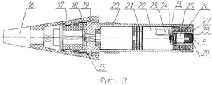
Разделяющийся реактивный снаряд содержит ракетный двигатель 15 с дном 14, отделяемую головную часть, имеющую в своем составе корпус 4 с дном 11, ВВ 6 и поражающие элементы 5, парашютный отсек 10 с парашютной системой 8 и зарядом отделения 13, поршнем 9 и узлом форсирования 7, а также взрывательное устройство 1.The separable missile contains a rocket engine 15 with a bottom 14, a detachable warhead, comprising a body 4 with a bottom 11, BB 6 and striking elements 5, a parachute compartment 10 with a parachute system 8 and a charge of the compartment 13, a piston 9 and a forcing unit 7 as well as an explosive device 1.
Головная часть снабжена центральным газоводом 3, газодинамически связывающим объем А аккумулирующего стакана 2 корпуса 4 с запоршневым рабочим объемом Б, содержащим заряд отделения, а в дне головной части выполнены осевые каналы 12, связывающие запоршневой объем Б с задонной компенсаторной зоной ракетного двигателя В.The head part is equipped with a central gas duct 3, which dynamically connects the volume A of the accumulating cup 2 of the housing 4 with the piston displacement B containing the charge of the compartment, and in the bottom of the head part there are axial channels 12 connecting the piston volume B with the backward compensating zone of the rocket engine B.
Взрывательное устройство имеет коническую 17 и цилиндрическую 20 части корпуса, в которых размещены электронное временное устройство 21, предохранительно-исполнительный механизм 22, реакционный датчик цели 16, инерционный ударный механизм 23 и исполнительный блок 25, снабженный пороховыми зарядами.The explosive device has a conical 17 and a cylindrical 20 body part, in which an electronic
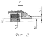
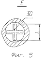
Исполнительный блок закреплен в хвостовой части цилиндрической трубы корпуса взрывателя и выполнен в виде двойного коаксиального стакана 27, в центральной части которого размещена пороховая петарда 28 системы воспламенения заряда отделения, а в периферийном кольцевом канале расположен детонатор 26 системы подрыва ВВ головной части. При этом дно стакана выполнено в виде разрывной мембраны с радиальными концентраторами напряжения 30, а пороховая петарда дополнительно снабжена усилительным пороховым зарядом 29.The executive unit is fixed in the tail of the cylindrical tube of the fuse case and is made in the form of a double
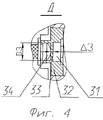
Исполнительный блок снабжен клапанным механизмом Д, закрепленным в центральном канале стакана со стороны вышибного заряда 24 ПИМа и выполненным в виде втулки 32, с противоположных сторон которой закреплены боек 34 и втулочный капсюль-воспламенитель 31, разделенные сплошной перегородкой 33, взаимодействующей с бойком при срабатывании вышибного заряда ПИМа и обеспечивающей за счет упругой деформации задействование втулочного капсюля-воспламенителя и воспламенение пороховой петарды.The actuating unit is equipped with a valve mechanism D fixed in the central channel of the beaker from the side of the
В зоне стыка конической и цилиндрической поверхностей корпуса взрывателя установлена толстостенная металлическая перемычка 19 с центральным каналом, перекрытым заглушкой с пазом 18 для размещения электрических цепей, связывающих электронные блоки составных элементов взрывателя. А над толстостенной перемычкой, в конической части корпуса взрывателя, выполнено ослабленное поперечное сечение 35, например, в виде кольцевой проточки.In the junction of the conical and cylindrical surfaces of the fuse case, a thick-
При этом внутренний диаметр центрального канала газовода D1 головной части составляет 0,8-1,1 диаметра центрального канала D2 коаксиального стакана, толщина слоя ВВ от внешнего диаметра газовода до среднего диаметра кольцевого детонатора Δ1 составляет 0,4-0,6 толщины детонатора Δ2. Одновременно, толщина упругой перегородки Δ3 исполнительного блока составляет 0,09-0,12 от диаметра D3 втулки клапанного механизма, а протяженность радиальных концентраторов напряжения L разрывной мембраны не превышает величину радиуса пороховой петарды D2.Moreover, the inner diameter of the central channel of the gas duct D 1 of the head is 0.8-1.1 of the diameter of the central channel D 2 of the coaxial cup, the thickness of the explosive layer from the outer diameter of the gas duct to the average diameter of the annular detonator Δ 1 is 0.4-0.6 thickness detonator Δ 2 . At the same time, the thickness of the elastic partition Δ 3 of the actuator block is 0.09-0.12 of the diameter D 3 of the valve sleeve, and the length of the radial stress concentrators L of the bursting membrane does not exceed the radius of the powder firecracker D 2 .
Разделяющийся реактивный снаряд работает следующим образом.Separating missile works as follows.
После старта разделяющегося снаряда, в момент окончания счета предварительно установленного времени дистанционного действия, электронно-временное устройство взрывателя 21 выдает электрический импульс ПИМу 22 и обеспечивает срабатывание его вышибного заряда 24. Продукты сгорания вышибного заряда через боек 34 передают ударную нагрузку на сплошную перегородку 33 и за счет упругой деформации ее осуществляют задействование втулочного капсюля-воспламенителя 31, который, в свою очередь, при срабатывании обеспечивает воспламенение пороховой петарды 28 исполнительного блока 25. Высокотемпературные продукты сгорания петарды заполняют центральную часть коаксиального стакана 27, воспламеняют усилительный пороховой заряд 29 и за счет избыточного давления стабильно раскрывают дно стакана, предотвращая перекрытие проходного сечения газовода 3.After the launch of the fissile shell, at the end of the counting of the pre-set time of the remote action, the electronic-temporary device of the
В дальнейшем продукты сгорания петарды и дополнительного порохового заряда по газоводу поступают в запоршневой объем Б и создают там условия, необходимые для разрушения узла форсирования 7, выполненного, например, в виде кольцевой проточки в корпусе ГЧ. Под действием давления на поршень 9 системы отделения осуществляется разделение снаряда, ввод в действие системы стабилизации и дальнейшее движение головной части происходит в требуемом угловом положении.In the future, the combustion products of the firecrackers and the additional powder charge through the gas duct enter the piston volume B and create the conditions there necessary for the destruction of the forcing unit 7, made, for example, in the form of an annular groove in the main body. Under the action of pressure on the piston 9 of the separation system, the projectile is separated, the stabilization system is put into operation and the head part moves further in the required angular position.
Необходимо отметить, что в процессе отделения головной части от ракетной продукты сгорания заряда отделения поступают в объем стакана корпуса А и (через осевые каналы в дне) в задонный компенсационный объем В, которые в процессе заполнения обеспечивают снижение максимального давления в зоне отделения, а в процессе отделения головной части от ракетной выполняют роль аккумулирующих полостей, обеспечивающих повышение скорости разделения снаряда.It should be noted that in the process of separating the warhead from the rocket, the products of combustion of the charge of the separation enter the volume of the cup body A and (through the axial channels in the bottom) into the backward compensation volume B, which during filling provide a decrease in the maximum pressure in the separation zone, and in the process separation of the warhead from the missile serves as accumulating cavities, providing an increase in the rate of separation of the projectile.
При встрече головной части с преградой срабатывает реакционный датчик цели 16 и по электрическим цепям выдает электрический импульс на ПИМ 22, который в свою очередь формирует детонационный импульс на срабатывание кольцевого детонатора 26, размещенного в периферийном отсеке коаксиального стакана 27 исполнительного блока 25. В случае отказа реакционного датчика цели при встрече с преградой происходит срабатывание инерционного ударного механизма 23, входящего в состав ПИМа с последующим срабатыванием кольцевого детонатора. Учитывая указанные выше рекомендации, подтвержденные опытным путем и связывающие толщину определенного слоя ВВ с толщиной детонатора, обеспечиваются рациональные условия для инициирования и полноты детонации ВВ, определяющие эффективность работы боеприпаса у цели.When the head part meets an obstacle, the reaction sensor of the
Дополнительно следует отметить, что в описанной конструкции РРС предложен ряд конструктивных мероприятий и соотношений, позволяющих повысить надежность и качество разделяющегося боеприпаса. Так, например, снабжение исполнительного блока клапанным механизмом обеспечивает не только надежное задействование втулочного капсюля-воспламенителя и воспламенение пороховой петарды, но и исключает повреждение узлов и механизмов ВУ от воздействия высокого давления и температуры газа в процессе отделения ГЧ от РЧ. Одновременно размещение в зоне стыка конической и цилиндрической поверхностей металлической перемычки, предотвращающей разрушение составных элементов и попадание посторонних предметов в исполнительный механизм, обеспечивается за счет того, что верхняя часть корпуса ВУ снабжена ослабленным сечением в виде кольцевой проточки (являющимся концентратором напряжения) для стабильного разрушения корпуса ВУ в заданном месте перед толстостенной перемычкой при встрече с преградой.In addition, it should be noted that in the described design of the RRS a number of constructive measures and ratios are proposed that can improve the reliability and quality of the munition. So, for example, supplying the actuator block with a valve mechanism provides not only reliable engagement of the plug-igniter and the ignition of the powder firecracker, but also eliminates damage to the components and mechanisms of the WW from high pressure and gas temperature in the process of separation of HF from RF. At the same time, the placement of a metal bridge in the junction area of the conical and cylindrical surfaces, which prevents the destruction of components and the ingress of foreign objects into the actuator, is ensured by the fact that the upper part of the casing is equipped with a weakened section in the form of an annular groove (which is a stress concentrator) for stable destruction of the casing WU in a given place in front of a thick-walled jumper when meeting with an obstacle.
Таким образом, выполнение конструкции разделяемого реактивного снаряда в соответствии с изобретением позволяет повысить надежность функционирования исполнительных органов боеприпаса, а также повысить эффективность работы его у цели.Thus, the design of a shared missile in accordance with the invention allows to increase the reliability of the functioning of the executive bodies of the munition, as well as to increase its efficiency at the target.
Изобретение может быть использовано при разработке снарядов с отделяемыми головными частями осколочно-фугасного действия и в первую очередь для реактивных систем залпового огня.The invention can be used in the development of shells with detachable warheads of high-explosive fragmentation, and primarily for multiple launch rocket systems.
Указанный положительный эффект подтвержден испытаниями опытных образцов отделяемых головных частей, выполненных в соответствии с изобретением.The specified positive effect is confirmed by testing prototypes of detachable warheads made in accordance with the invention.
В настоящее время разработана конструкторская документация, проведены государственные испытания, намечено серийное производство.Currently, design documentation has been developed, state tests have been carried out, and mass production is scheduled.
Claims (1)
Priority Applications (1)
| Application Number | Priority Date | Filing Date | Title |
|---|---|---|---|
| RU2013110881/11A RU2522537C1 (en) | 2013-03-13 | 2013-03-13 | Detachable rocket-propelled missile |
Applications Claiming Priority (1)
| Application Number | Priority Date | Filing Date | Title |
|---|---|---|---|
| RU2013110881/11A RU2522537C1 (en) | 2013-03-13 | 2013-03-13 | Detachable rocket-propelled missile |
Publications (1)
| Publication Number | Publication Date |
|---|---|
| RU2522537C1 true RU2522537C1 (en) | 2014-07-20 |
Family
ID=51217400
Family Applications (1)
| Application Number | Title | Priority Date | Filing Date |
|---|---|---|---|
| RU2013110881/11A RU2522537C1 (en) | 2013-03-13 | 2013-03-13 | Detachable rocket-propelled missile |
Country Status (1)
| Country | Link |
|---|---|
| RU (1) | RU2522537C1 (en) |
Cited By (2)
| Publication number | Priority date | Publication date | Assignee | Title |
|---|---|---|---|---|
| RU170324U1 (en) * | 2016-04-21 | 2017-04-21 | Акционерное общество "Новосибирский завод искусственного волокна" | SEPARATING REACTIVE APPARATUS |
| RU2722193C1 (en) * | 2019-05-28 | 2020-05-28 | Российская Федерация, от имени которой выступает Министерство обороны Российской Федерации | Separated fragmentation-demolition head part of projectile |
Citations (3)
| Publication number | Priority date | Publication date | Assignee | Title |
|---|---|---|---|---|
| RU2230288C1 (en) * | 2002-11-21 | 2004-06-10 | Федеральное Государственное унитарное предприятие "Государственное научно-производственное предприятие "Сплав" | Separating jet projectile |
| US20080307994A1 (en) * | 2004-01-15 | 2008-12-18 | Bae System Bofors Ab | Warhead |
| US20120137917A1 (en) * | 2010-12-06 | 2012-06-07 | Golden Peter J | Low shock rocket body separation |
-
2013
- 2013-03-13 RU RU2013110881/11A patent/RU2522537C1/en active
Patent Citations (3)
| Publication number | Priority date | Publication date | Assignee | Title |
|---|---|---|---|---|
| RU2230288C1 (en) * | 2002-11-21 | 2004-06-10 | Федеральное Государственное унитарное предприятие "Государственное научно-производственное предприятие "Сплав" | Separating jet projectile |
| US20080307994A1 (en) * | 2004-01-15 | 2008-12-18 | Bae System Bofors Ab | Warhead |
| US20120137917A1 (en) * | 2010-12-06 | 2012-06-07 | Golden Peter J | Low shock rocket body separation |
Non-Patent Citations (1)
| Title |
|---|
| . . * |
Cited By (2)
| Publication number | Priority date | Publication date | Assignee | Title |
|---|---|---|---|---|
| RU170324U1 (en) * | 2016-04-21 | 2017-04-21 | Акционерное общество "Новосибирский завод искусственного волокна" | SEPARATING REACTIVE APPARATUS |
| RU2722193C1 (en) * | 2019-05-28 | 2020-05-28 | Российская Федерация, от имени которой выступает Министерство обороны Российской Федерации | Separated fragmentation-demolition head part of projectile |
Similar Documents
| Publication | Publication Date | Title |
|---|---|---|
| RU134628U1 (en) | EXPLOSION PROTECTIVE MECHANISM | |
| US8931415B2 (en) | Initiation systems for explosive devices, scalable output explosive devices including initiation systems, and related methods | |
| US20120312184A1 (en) | Adaptable smart warhead and method for use | |
| CN109556468B (en) | Large-caliber smoothbore explosive cartridge warhead mechanical trigger fuse | |
| CN105890473A (en) | Fuze device for artificial precipitation projectile | |
| RU2540987C1 (en) | Fuse for missile projectiles and method of its application | |
| NO316339B1 (en) | Br degree no degree stainless, ballistic blasting projectile | |
| RU2522537C1 (en) | Detachable rocket-propelled missile | |
| KR20220030251A (en) | Warhead embedded ammunition with shells | |
| RU2401980C1 (en) | Signal mine of non-lethal effect | |
| FI86108C (en) | PATRON FOER HAGELGEVAER MED EXPLOSIV PROJEKTIL. | |
| US2455603A (en) | Fuse | |
| RU2705859C1 (en) | Separation bolt with obturation system | |
| US3888179A (en) | Initiator for incendiary pellet | |
| CN201093952Y (en) | Combined type smoke gun powder long prolongation exploding apparatus | |
| RU2645099C1 (en) | Detonation engine | |
| RU2439470C1 (en) | Cartridge | |
| RU145954U1 (en) | HEAD EXPLOSION OF THE ARTILLERY SMALL-BAR EQUIPMENT | |
| RU2688174C2 (en) | Universal initiation means and device based on it | |
| RU2809456C1 (en) | Cassette warhead | |
| US10969212B1 (en) | Multipurpose munition for personnel and materiel defeat | |
| RU2412426C1 (en) | Nose fuse | |
| RU2255300C1 (en) | Nose fuse | |
| RU2202760C2 (en) | Cluster war head | |
| US2892400A (en) | Projectile for simulating firing of automatic weapons |