RU2516021C2 - Monocrystalline welding of materials hardened in one direction - Google Patents
Monocrystalline welding of materials hardened in one direction Download PDFInfo
- Publication number
- RU2516021C2 RU2516021C2 RU2012122743/02A RU2012122743A RU2516021C2 RU 2516021 C2 RU2516021 C2 RU 2516021C2 RU 2012122743/02 A RU2012122743/02 A RU 2012122743/02A RU 2012122743 A RU2012122743 A RU 2012122743A RU 2516021 C2 RU2516021 C2 RU 2516021C2
- Authority
- RU
- Russia
- Prior art keywords
- powder
- substrate
- temperature
- particles
- laser beam
- Prior art date
Links
Images


Classifications
-
- B—PERFORMING OPERATIONS; TRANSPORTING
- B23—MACHINE TOOLS; METAL-WORKING NOT OTHERWISE PROVIDED FOR
- B23K—SOLDERING OR UNSOLDERING; WELDING; CLADDING OR PLATING BY SOLDERING OR WELDING; CUTTING BY APPLYING HEAT LOCALLY, e.g. FLAME CUTTING; WORKING BY LASER BEAM
- B23K26/00—Working by laser beam, e.g. welding, cutting or boring
- B23K26/34—Laser welding for purposes other than joining
-
- C—CHEMISTRY; METALLURGY
- C30—CRYSTAL GROWTH
- C30B—SINGLE-CRYSTAL GROWTH; UNIDIRECTIONAL SOLIDIFICATION OF EUTECTIC MATERIAL OR UNIDIRECTIONAL DEMIXING OF EUTECTOID MATERIAL; REFINING BY ZONE-MELTING OF MATERIAL; PRODUCTION OF A HOMOGENEOUS POLYCRYSTALLINE MATERIAL WITH DEFINED STRUCTURE; SINGLE CRYSTALS OR HOMOGENEOUS POLYCRYSTALLINE MATERIAL WITH DEFINED STRUCTURE; AFTER-TREATMENT OF SINGLE CRYSTALS OR A HOMOGENEOUS POLYCRYSTALLINE MATERIAL WITH DEFINED STRUCTURE; APPARATUS THEREFOR
- C30B13/00—Single-crystal growth by zone-melting; Refining by zone-melting
- C30B13/16—Heating of the molten zone
- C30B13/22—Heating of the molten zone by irradiation or electric discharge
- C30B13/24—Heating of the molten zone by irradiation or electric discharge using electromagnetic waves
-
- B—PERFORMING OPERATIONS; TRANSPORTING
- B23—MACHINE TOOLS; METAL-WORKING NOT OTHERWISE PROVIDED FOR
- B23K—SOLDERING OR UNSOLDERING; WELDING; CLADDING OR PLATING BY SOLDERING OR WELDING; CUTTING BY APPLYING HEAT LOCALLY, e.g. FLAME CUTTING; WORKING BY LASER BEAM
- B23K26/00—Working by laser beam, e.g. welding, cutting or boring
- B23K26/20—Bonding
- B23K26/32—Bonding taking account of the properties of the material involved
-
- B—PERFORMING OPERATIONS; TRANSPORTING
- B23—MACHINE TOOLS; METAL-WORKING NOT OTHERWISE PROVIDED FOR
- B23K—SOLDERING OR UNSOLDERING; WELDING; CLADDING OR PLATING BY SOLDERING OR WELDING; CUTTING BY APPLYING HEAT LOCALLY, e.g. FLAME CUTTING; WORKING BY LASER BEAM
- B23K26/00—Working by laser beam, e.g. welding, cutting or boring
- B23K26/34—Laser welding for purposes other than joining
- B23K26/342—Build-up welding
-
- B—PERFORMING OPERATIONS; TRANSPORTING
- B23—MACHINE TOOLS; METAL-WORKING NOT OTHERWISE PROVIDED FOR
- B23K—SOLDERING OR UNSOLDERING; WELDING; CLADDING OR PLATING BY SOLDERING OR WELDING; CUTTING BY APPLYING HEAT LOCALLY, e.g. FLAME CUTTING; WORKING BY LASER BEAM
- B23K35/00—Rods, electrodes, materials, or media, for use in soldering, welding, or cutting
- B23K35/001—Interlayers, transition pieces for metallurgical bonding of workpieces
- B23K35/007—Interlayers, transition pieces for metallurgical bonding of workpieces at least one of the workpieces being of copper or another noble metal
-
- B—PERFORMING OPERATIONS; TRANSPORTING
- B23—MACHINE TOOLS; METAL-WORKING NOT OTHERWISE PROVIDED FOR
- B23K—SOLDERING OR UNSOLDERING; WELDING; CLADDING OR PLATING BY SOLDERING OR WELDING; CUTTING BY APPLYING HEAT LOCALLY, e.g. FLAME CUTTING; WORKING BY LASER BEAM
- B23K35/00—Rods, electrodes, materials, or media, for use in soldering, welding, or cutting
- B23K35/02—Rods, electrodes, materials, or media, for use in soldering, welding, or cutting characterised by mechanical features, e.g. shape
- B23K35/0222—Rods, electrodes, materials, or media, for use in soldering, welding, or cutting characterised by mechanical features, e.g. shape for use in soldering, brazing
- B23K35/0244—Powders, particles or spheres; Preforms made therefrom
-
- C—CHEMISTRY; METALLURGY
- C30—CRYSTAL GROWTH
- C30B—SINGLE-CRYSTAL GROWTH; UNIDIRECTIONAL SOLIDIFICATION OF EUTECTIC MATERIAL OR UNIDIRECTIONAL DEMIXING OF EUTECTOID MATERIAL; REFINING BY ZONE-MELTING OF MATERIAL; PRODUCTION OF A HOMOGENEOUS POLYCRYSTALLINE MATERIAL WITH DEFINED STRUCTURE; SINGLE CRYSTALS OR HOMOGENEOUS POLYCRYSTALLINE MATERIAL WITH DEFINED STRUCTURE; AFTER-TREATMENT OF SINGLE CRYSTALS OR A HOMOGENEOUS POLYCRYSTALLINE MATERIAL WITH DEFINED STRUCTURE; APPARATUS THEREFOR
- C30B11/00—Single-crystal growth by normal freezing or freezing under temperature gradient, e.g. Bridgman-Stockbarger method
-
- C—CHEMISTRY; METALLURGY
- C30—CRYSTAL GROWTH
- C30B—SINGLE-CRYSTAL GROWTH; UNIDIRECTIONAL SOLIDIFICATION OF EUTECTIC MATERIAL OR UNIDIRECTIONAL DEMIXING OF EUTECTOID MATERIAL; REFINING BY ZONE-MELTING OF MATERIAL; PRODUCTION OF A HOMOGENEOUS POLYCRYSTALLINE MATERIAL WITH DEFINED STRUCTURE; SINGLE CRYSTALS OR HOMOGENEOUS POLYCRYSTALLINE MATERIAL WITH DEFINED STRUCTURE; AFTER-TREATMENT OF SINGLE CRYSTALS OR A HOMOGENEOUS POLYCRYSTALLINE MATERIAL WITH DEFINED STRUCTURE; APPARATUS THEREFOR
- C30B29/00—Single crystals or homogeneous polycrystalline material with defined structure characterised by the material or by their shape
- C30B29/10—Inorganic compounds or compositions
- C30B29/52—Alloys
-
- F—MECHANICAL ENGINEERING; LIGHTING; HEATING; WEAPONS; BLASTING
- F01—MACHINES OR ENGINES IN GENERAL; ENGINE PLANTS IN GENERAL; STEAM ENGINES
- F01D—NON-POSITIVE DISPLACEMENT MACHINES OR ENGINES, e.g. STEAM TURBINES
- F01D5/00—Blades; Blade-carrying members; Heating, heat-insulating, cooling or antivibration means on the blades or the members
- F01D5/005—Repairing methods or devices
-
- F—MECHANICAL ENGINEERING; LIGHTING; HEATING; WEAPONS; BLASTING
- F01—MACHINES OR ENGINES IN GENERAL; ENGINE PLANTS IN GENERAL; STEAM ENGINES
- F01D—NON-POSITIVE DISPLACEMENT MACHINES OR ENGINES, e.g. STEAM TURBINES
- F01D5/00—Blades; Blade-carrying members; Heating, heat-insulating, cooling or antivibration means on the blades or the members
- F01D5/12—Blades
- F01D5/28—Selecting particular materials; Particular measures relating thereto; Measures against erosion or corrosion
- F01D5/286—Particular treatment of blades, e.g. to increase durability or resistance against corrosion or erosion
-
- B—PERFORMING OPERATIONS; TRANSPORTING
- B23—MACHINE TOOLS; METAL-WORKING NOT OTHERWISE PROVIDED FOR
- B23K—SOLDERING OR UNSOLDERING; WELDING; CLADDING OR PLATING BY SOLDERING OR WELDING; CUTTING BY APPLYING HEAT LOCALLY, e.g. FLAME CUTTING; WORKING BY LASER BEAM
- B23K2101/00—Articles made by soldering, welding or cutting
- B23K2101/001—Turbines
-
- B—PERFORMING OPERATIONS; TRANSPORTING
- B23—MACHINE TOOLS; METAL-WORKING NOT OTHERWISE PROVIDED FOR
- B23K—SOLDERING OR UNSOLDERING; WELDING; CLADDING OR PLATING BY SOLDERING OR WELDING; CUTTING BY APPLYING HEAT LOCALLY, e.g. FLAME CUTTING; WORKING BY LASER BEAM
- B23K2103/00—Materials to be soldered, welded or cut
- B23K2103/08—Non-ferrous metals or alloys
-
- B—PERFORMING OPERATIONS; TRANSPORTING
- B23—MACHINE TOOLS; METAL-WORKING NOT OTHERWISE PROVIDED FOR
- B23K—SOLDERING OR UNSOLDERING; WELDING; CLADDING OR PLATING BY SOLDERING OR WELDING; CUTTING BY APPLYING HEAT LOCALLY, e.g. FLAME CUTTING; WORKING BY LASER BEAM
- B23K2103/00—Materials to be soldered, welded or cut
- B23K2103/18—Dissimilar materials
- B23K2103/26—Alloys of Nickel and Cobalt and Chromium
-
- B—PERFORMING OPERATIONS; TRANSPORTING
- B23—MACHINE TOOLS; METAL-WORKING NOT OTHERWISE PROVIDED FOR
- B23K—SOLDERING OR UNSOLDERING; WELDING; CLADDING OR PLATING BY SOLDERING OR WELDING; CUTTING BY APPLYING HEAT LOCALLY, e.g. FLAME CUTTING; WORKING BY LASER BEAM
- B23K2103/00—Materials to be soldered, welded or cut
- B23K2103/50—Inorganic material, e.g. metals, not provided for in B23K2103/02 – B23K2103/26
-
- F—MECHANICAL ENGINEERING; LIGHTING; HEATING; WEAPONS; BLASTING
- F05—INDEXING SCHEMES RELATING TO ENGINES OR PUMPS IN VARIOUS SUBCLASSES OF CLASSES F01-F04
- F05D—INDEXING SCHEME FOR ASPECTS RELATING TO NON-POSITIVE-DISPLACEMENT MACHINES OR ENGINES, GAS-TURBINES OR JET-PROPULSION PLANTS
- F05D2230/00—Manufacture
- F05D2230/20—Manufacture essentially without removing material
- F05D2230/23—Manufacture essentially without removing material by permanently joining parts together
- F05D2230/232—Manufacture essentially without removing material by permanently joining parts together by welding
- F05D2230/234—Laser welding
-
- F—MECHANICAL ENGINEERING; LIGHTING; HEATING; WEAPONS; BLASTING
- F05—INDEXING SCHEMES RELATING TO ENGINES OR PUMPS IN VARIOUS SUBCLASSES OF CLASSES F01-F04
- F05D—INDEXING SCHEME FOR ASPECTS RELATING TO NON-POSITIVE-DISPLACEMENT MACHINES OR ENGINES, GAS-TURBINES OR JET-PROPULSION PLANTS
- F05D2230/00—Manufacture
- F05D2230/30—Manufacture with deposition of material
- F05D2230/31—Layer deposition
- F05D2230/312—Layer deposition by plasma spraying
-
- F—MECHANICAL ENGINEERING; LIGHTING; HEATING; WEAPONS; BLASTING
- F05—INDEXING SCHEMES RELATING TO ENGINES OR PUMPS IN VARIOUS SUBCLASSES OF CLASSES F01-F04
- F05D—INDEXING SCHEME FOR ASPECTS RELATING TO NON-POSITIVE-DISPLACEMENT MACHINES OR ENGINES, GAS-TURBINES OR JET-PROPULSION PLANTS
- F05D2230/00—Manufacture
- F05D2230/80—Repairing, retrofitting or upgrading methods
-
- F—MECHANICAL ENGINEERING; LIGHTING; HEATING; WEAPONS; BLASTING
- F05—INDEXING SCHEMES RELATING TO ENGINES OR PUMPS IN VARIOUS SUBCLASSES OF CLASSES F01-F04
- F05D—INDEXING SCHEME FOR ASPECTS RELATING TO NON-POSITIVE-DISPLACEMENT MACHINES OR ENGINES, GAS-TURBINES OR JET-PROPULSION PLANTS
- F05D2230/00—Manufacture
- F05D2230/90—Coating; Surface treatment
-
- F—MECHANICAL ENGINEERING; LIGHTING; HEATING; WEAPONS; BLASTING
- F05—INDEXING SCHEMES RELATING TO ENGINES OR PUMPS IN VARIOUS SUBCLASSES OF CLASSES F01-F04
- F05D—INDEXING SCHEME FOR ASPECTS RELATING TO NON-POSITIVE-DISPLACEMENT MACHINES OR ENGINES, GAS-TURBINES OR JET-PROPULSION PLANTS
- F05D2300/00—Materials; Properties thereof
- F05D2300/60—Properties or characteristics given to material by treatment or manufacturing
- F05D2300/606—Directionally-solidified crystalline structures
-
- F—MECHANICAL ENGINEERING; LIGHTING; HEATING; WEAPONS; BLASTING
- F05—INDEXING SCHEMES RELATING TO ENGINES OR PUMPS IN VARIOUS SUBCLASSES OF CLASSES F01-F04
- F05D—INDEXING SCHEME FOR ASPECTS RELATING TO NON-POSITIVE-DISPLACEMENT MACHINES OR ENGINES, GAS-TURBINES OR JET-PROPULSION PLANTS
- F05D2300/00—Materials; Properties thereof
- F05D2300/60—Properties or characteristics given to material by treatment or manufacturing
- F05D2300/607—Monocrystallinity
-
- Y—GENERAL TAGGING OF NEW TECHNOLOGICAL DEVELOPMENTS; GENERAL TAGGING OF CROSS-SECTIONAL TECHNOLOGIES SPANNING OVER SEVERAL SECTIONS OF THE IPC; TECHNICAL SUBJECTS COVERED BY FORMER USPC CROSS-REFERENCE ART COLLECTIONS [XRACs] AND DIGESTS
- Y02—TECHNOLOGIES OR APPLICATIONS FOR MITIGATION OR ADAPTATION AGAINST CLIMATE CHANGE
- Y02T—CLIMATE CHANGE MITIGATION TECHNOLOGIES RELATED TO TRANSPORTATION
- Y02T50/00—Aeronautics or air transport
- Y02T50/60—Efficient propulsion technologies, e.g. for aircraft
Landscapes
- Engineering & Computer Science (AREA)
- Chemical & Material Sciences (AREA)
- Mechanical Engineering (AREA)
- Physics & Mathematics (AREA)
- Optics & Photonics (AREA)
- Materials Engineering (AREA)
- General Engineering & Computer Science (AREA)
- Crystallography & Structural Chemistry (AREA)
- Plasma & Fusion (AREA)
- Metallurgy (AREA)
- Organic Chemistry (AREA)
- Inorganic Chemistry (AREA)
- Electromagnetism (AREA)
- Turbine Rotor Nozzle Sealing (AREA)
- Laser Beam Processing (AREA)
- Other Surface Treatments For Metallic Materials (AREA)
Abstract
Description
Изобретение относится к способу сварки направленно упрочненных металлических материалов.The invention relates to a method for welding directionally hardened metal materials.
γ′-упрочненные SX жаропрочные сплавы на никелевой основе невозможно ни посредством обычных способов сварки, ни посредством высокоэнергетичных способов (лазером, электронным лучом) со сходными присадочными материалами в перекрывающихся сварочных дорожках сваривать наплавкой одного или нескольких слоев. Проблема заключается в том, что уже при отдельной сварочной дорожке в краевой области вблизи поверхности образуется структура с неправильной ориентацией. Для последующей перекрывающейся дорожки это означает, что фронт затвердевания (кристаллизации) в этой области не имеет SX центра кристаллизации, и область с неправильной ориентацией (не-SX структура) распространяется далее в область перекрытия. Это приводит к образованию трещин в этой области.γ′-hardened SX heat-resistant nickel-based alloys cannot be welded using one or several layers by welding using overlapping welding paths either by conventional welding methods or by high-energy methods (laser, electron beam) with similar filler materials. The problem is that even with a separate welding path in the edge region near the surface, a structure with an incorrect orientation is formed. For the subsequent overlapping track, this means that the solidification front (crystallization) in this region does not have an SX crystallization center, and the region with an incorrect orientation (non-SX structure) extends further to the overlapping region. This leads to the formation of cracks in this area.
Применявшиеся до сих пор способы сварки не в состоянии создать для γ′-упрочненных SX жаропрочных сплавов на никелевой основе наплавленный металл в обработке перекрытия в одном или нескольких слоях сходным образом с идентичной SX-структурой. При отдельной дорожке на SX-подложке локальные условия кристаллизации варьируются таким образом, что в зависимости от положения инициируется дендритный рост исходя от основных стволов или вторичных ветвей. При этом из различных возможных дендритных направлений роста проявляются таковые с наиболее благоприятными условиями роста, то есть с наименьшим углом наклона к температурному градиенту. Причина для образования неправильной ориентации в SX-структуре при порошковой наплавке γ′-упрочненных SX жаропрочных сплавов на никелевой основе в настоящее время не полностью ясна. Предполагают, что при столкновении друг с другом дендритов с различных направлений роста, возможно, вторичные ветви разрушаются и служат в качестве центров кристаллизации для образования структуры с неправильной ориентацией. Кроме того, в краевой области вблизи поверхности не полностью расплавленные частички порошка в расплаве могут служить в качестве центров кристаллизации для образования структуры с неправильной ориентацией. Поэтому для решения проблемы предлагается технологический процесс для порошковой наплавки γ′-упрочненных SX жаропрочных сплавов на никелевой основе, при котором реализуются условия роста, которые благоприятствуют только одному направлению роста для дендритов. Кроме того, технологический процесс обеспечивает полное расплавление частиц порошка в расплаве.The welding methods used so far are not able to create for γ′-hardened SX heat-resistant nickel-based alloys a deposited metal in the processing of the overlap in one or more layers in a similar way with an identical SX structure. With a separate track on the SX substrate, the local crystallization conditions vary so that depending on the position, dendritic growth is initiated based on the main trunks or secondary branches. Moreover, from various possible dendritic growth directions, those with the most favorable growth conditions, that is, with the smallest angle of inclination to the temperature gradient, are manifested. The reason for the formation of an incorrect orientation in the SX structure during powder surfacing of γ′-hardened SX heat-resistant nickel-based alloys is currently not completely clear. It is suggested that, when dendrites collide with each other from different growth directions, it is possible that secondary branches are destroyed and serve as crystallization centers to form a structure with an incorrect orientation. In addition, in the edge region near the surface, incompletely melted powder particles in the melt can serve as crystallization centers for the formation of a structure with an incorrect orientation. Therefore, to solve the problem, a technological process is proposed for powder surfacing of γ′-hardened SX heat-resistant nickel-based alloys under which growth conditions are realized that favor only one growth direction for dendrites. In addition, the process ensures complete melting of the powder particles in the melt.
Поэтому задачей изобретения является решение вышеописанной проблемы.Therefore, an object of the invention is to solve the above problem.
Эта задача решается способом согласно пункту 1 формулы изобретения.This problem is solved by the method according to paragraph 1 of the claims.
Для решения этой технической проблемы образования немонокристаллической структуры в близкой к поверхности краевой области отдельной дорожки предложен технологический процесс для наплавки лазерным излучением, при котором эта проблема не возникает или возникает в такой малой степени, что возможна обработка перекрытия (соединения внахлестку) в один или несколько слоев без образования трещин при комнатной температуре.To solve this technical problem of the formation of a non-monocrystalline structure in the edge region of a separate track close to the surface, a technological process for laser cladding has been proposed in which this problem does not occur or arises to such a small extent that processing of the overlap (lap joint) into one or several layers is possible no cracking at room temperature.
В зависимых пунктах формулы изобретения охарактеризованы другие предпочтительные меры, которые любым образом могут комбинироваться друг с другом для достижения дополнительных преимуществ.The dependent claims describe other preferred measures that can be combined with each other in any way to achieve additional benefits.
На чертежах показано следующее:The drawings show the following:
Фиг.1 - схематичное выполнение способа,Figure 1 - schematic implementation of the method,
Фиг.2 - газовая турбина,Figure 2 - gas turbine,
Фиг.3 - лопатка турбины,Figure 3 - turbine blade,
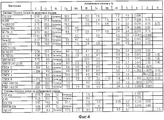
Фиг.4 - список жаропрочных сплавов.4 is a list of heat resistant alloys.
Описание и чертежи представляют только примеры выполнения изобретения.The description and drawings represent only examples of the invention.
На фиг.1 схематично представлен ход выполнения способа с устройством 1.Figure 1 schematically shows the progress of the method with the device 1.
Ремонтируемый конструктивный элемент 120, 130 имеет подложку 4 из жаропрочного сплава, в частности, жаропрочного сплава на никелевой основе согласно фиг.4.The repairable
Конкретно, подложка 4 состоит из жаропрочного сплава на никелевой основе.Specifically, the
Подложка 4 ремонтируется тем, что новый материал 7, в частности, посредством порошка, наносится на поверхность 5 подложки 4 посредством наплавки.The
Это осуществляется посредством подачи материала 7 и сварочного луча, предпочтительно лазерного луча 10 лазера, который расплавляет по меньшей мере подаваемый материал 7 и предпочтительно также частично подложку 4.This is done by feeding the material 7 and a welding beam, preferably a
При этом предпочтительно применяется порошок. Предпочтительно диаметр частиц 7 порошка настолько мал, что лазерный луч их полностью расплавляет, и в результате обеспечивается достаточно высокая температура частиц 7.In this case, a powder is preferably used. Preferably, the particle diameter 7 of the powder is so small that the laser beam completely melts them, and as a result, a sufficiently high temperature of the particles 7 is ensured.
При этом на подложке 4 во время сварки имеется наплавленная область 16 и примыкающий к ней фронт 19 затвердевания (кристаллизации) и перед ним уже вновь затвердевшая область 13.At the same time, on the
Устройство, соответствующее изобретению, предпочтительно содержит лазер (не показан) с блоком подачи порошка и систему перемещения (не показана), с помощью которой зона взаимодействия лазерного луча и область попадания для порошка 7 на поверхности 5 подложки могут перемещаться. Конструктивный элемент (подложка 4) при этом предпочтительно не нагревается и не подвергается старению за счет термообработки.The device according to the invention preferably comprises a laser (not shown) with a powder supply unit and a moving system (not shown), with which the interaction zone of the laser beam and the contact area for the powder 7 on the surface 5 of the substrate can be moved. The structural element (substrate 4) in this case is preferably not heated and does not undergo aging due to heat treatment.
Восстанавливаемая область подложки 4 предпочтительно подвергается наплавке слоями.The recovery region of the
Слои предпочтительно наносятся в форме меандра, однонаправленно или двунаправленно, причем вектора сканирования меандровых перемещений от слоя к слою предпочтительно поворачиваются на 90°, чтобы избежать ошибок привязки между слоями.The layers are preferably applied in the form of a meander, unidirectionally or bi-directionally, and the scanning vectors of meander movements from layer to layer are preferably rotated 90 ° to avoid binding errors between layers.
Дендриты 31 в подложке 4 и дендриты 34 в наносимой области 13 представлены на фиг.1. Также представлена система 25 координат. Подложка 4 перемещается относительно х-направления 22 со скоростью VV сканирования.Dendrites 31 in the
На фронте 19 кристаллизации имеется z-температурный градиент ![]()
![]()
Процесс сварки выполняется с параметрами способа относительно подачи VV, лазерной мощности, диаметра луча и расхода порошка, которые приводят к локальной ориентации температурного градиента на фронте кристаллизации, который меньше, чем 45°, к направлению дендритов 31 в подложке 4. За счет этого гарантируется, что поддерживается исключительно направление роста дендритов 34, которое продолжает направление 32 дендритов в подложке 4. Для этого необходим радиус луча, который гарантирует, что часть линий трех фаз, которая окаймляет фронт 19 кристаллизации, полностью перекрывается лазерным лучом.The welding process is performed with the parameters of the method relative to the feed V V , laser power, beam diameter and powder flow rate, which lead to a local orientation of the temperature gradient at the crystallization front, which is less than 45 °, to the direction of dendrites 31 in the
Аппроксимирующее условие для подходящего наклона фронта 19 кристаллизации к направлению 32 дендритов для дендритов 31 в подложке 4 имеет вид:The approximating condition for a suitable slope of the crystallization front 19 to the direction 32 of dendrites for dendrites 31 in the

А: степень поглощения подложкой,A: the degree of absorption by the substrate,
IL: интенсивность лазера,I L : laser intensity
VV: скорость сканирования,V V : scan speed,
λ: теплопроводность подложки,λ: thermal conductivity of the substrate,
T: температура.T: temperature.
Из этого условия получается в зависимости от материала окно процесса относительно интенсивности лазерного излучения (примерно в форме цилиндра), радиуса луча относительно фокуса порошкового пучка, скорости VV подачи и расхода порошка.Depending on the material, a process window is obtained relative to the intensity of laser radiation (approximately in the form of a cylinder), the radius of the beam relative to the focus of the powder beam, the feed rate V V and the powder flow rate.
Посредством полного перекрытия расплава лазерным излучением при коаксиальном ведении процесса гарантируется более длительное время взаимодействия частиц порошка с лазерным излучением и, тем самым, более высокая температура частиц при контакте с расплавом.By completely blocking the melt with laser radiation in a coaxial process, a longer interaction time between the powder particles and the laser radiation and thereby a higher temperature of the particles in contact with the melt are guaranteed.
Диаметр частиц и заданное тем самым время взаимодействия должны обусловить температурный уровень, достаточно высокий для полной наплавки. Достаточно высокий температурный уровень расплава при заданной температуре частиц и времени выдержки в расплаве должен обеспечить то, что частицы полностью перейдут в расплав.The particle diameter and thereby the interaction time should determine a temperature level high enough for complete surfacing. A sufficiently high temperature level of the melt at a given temperature of the particles and the exposure time in the melt should ensure that the particles completely go into the melt.
За счет описанных выше параметров способа и механизмов обеспечиваются предпосылки для эпитаксиального монокристаллического роста в наплавленном металле с идентичной ориентацией дендритов в подложке. За счет того, что в процессе сварки активируется только одно направление роста дендритов по нормали к поверхности, при затвердевании облегчается протекание расплава в междендритное пространство и предотвращается образование высокотемпературных трещин. Это дает в результате качество сварки, которое для структурной сварки (например, с целью ремонта или сцепления в высоконагруженной области конструктивного элемента) является приемлемым.Due to the parameters of the method and mechanisms described above, the prerequisites for epitaxial single crystal growth in the deposited metal with the identical orientation of the dendrites in the substrate are provided. Due to the fact that during the welding process only one direction of dendrite growth is activated normal to the surface, during solidification, the melt flows into the interdendritic space and the formation of high-temperature cracks is prevented. This results in a welding quality that is acceptable for structural welding (for example, for the purpose of repair or adhesion in a highly loaded region of a structural element).
Фиг.2 показывает для примера газовую турбину 100 в продольном сечении.Figure 2 shows, for example, a
Газовая турбина 100 имеет внутри установленный с возможностью вращения вокруг оси 102 вращения ротор 103 с валом 101, который также называется ротором турбины.The
Вдоль ротора 103 следуют друг за другом корпус 104 воздухозаборника, компрессор 105, камера 110 сгорания, выполненная, например, торообразной, в частности, кольцевая камера сгорания, с множеством коаксиально размещенных горелок 107, турбина 108 и газоотводный корпус 109.Along the
Кольцевая камера 110 сгорания сообщается с, например, кольцевым каналом 111 горячего газа. Там, например, четыре включенные друг за другом ступени 112 турбины образуют турбину 108.An
Каждая ступень 112 турбины образована, например, из двух лопаточных колец. При наблюдении в направлении течения рабочей среды 113, в канале 111 горячего газа за рядом 115 направляющих лопаток следует ряд 125, образованный из рабочих лопаток 120.Each
При этом направляющие лопатки 130 закреплены на внутреннем корпусе 138 статора 143, в то время как рабочие лопатки 120 ряда 125, размещены на роторе 103, например, посредством диска 133 турбины.In this case, the
С ротором 103 связан генератор или рабочая машина (не показано).A generator or a working machine (not shown) is connected to the
Во время работы газовой турбины 100 посредством компрессора 105 через корпус 104 воздухозаборника воздух 135 засасывается и сжимается. Сжатый воздух, подготовленный на выходе со стороны турбины компрессора 105, направляется к горелкам 107 и там смешивается с горючим средством. Затем смесь с образованием рабочей среды 113 сжигается в камере 110 сгорания. Оттуда рабочая среда 113 течет вдоль канала 111 горячего газа мимо направляющих лопаток 130 и рабочих лопаток 120. На рабочих лопатках 120 рабочая среда 113 расширяется, передавая импульс, так что рабочие лопатки 120 приводят в действие ротор 103, а последний - связанную с ним рабочую машину.During operation of the
Конструктивные элементы, открытые для горячей рабочей среды 113, подвергаются в процессе работы газовой турбины 100 термическим нагрузкам. Направляющие лопатки 130 и рабочие лопатки 120 первой при наблюдении в направлении течения рабочей среды 113 ступени 112 турбины, наряду с облицовывающими кольцевую камеру 110 сгорания элементами теплозащитного экрана, больше всего нагружаются термически.Structural elements that are open to the
Чтобы выдерживать существующие там температуры, они могут охлаждаться посредством охладителя.In order to withstand the temperatures existing there, they can be cooled by means of a cooler.
Также подложки конструктивных элементов могут иметь направленную структуру, то есть они являются монокристаллическими (SX-структура) или имеют только продольно ориентированные зерна (DS-структура).Also, the substrates of structural elements can have a directional structure, that is, they are single-crystal (SX-structure) or have only longitudinally oriented grains (DS-structure).
В качестве материала для конструктивных элементов, в частности, для лопаток 120, 130 турбины и конструктивных элементов камеры 110 сгорания применяются, например, жаропрочные сплавы на основе железа, никеля или кобальта.As a material for structural elements, in particular for
Такие жаропрочные сплавы известны, например, из ЕР 1204776 В1, ЕР 1306454, ЕР 1319729 А1, WO 99/67435 или WO 00/44949.Such heat-resistant alloys are known, for example, from EP 1204776 B1, EP 1306454, EP 1319729 A1, WO 99/67435 or WO 00/44949.
Также лопатки 120, 130 могут иметь покрытия против коррозии (MCrAlX; где M - по меньшей мере один элемент из группы железа (Fe), кобальта (Co), никеля (Ni), X - активный элемент, представляющий иттрий (Y) и/или кремний, скандий (Sc) и/или по меньшей мере один элемент из редкоземельных металлов или гафний). Такие сплавы известны из ЕР 0486489 В1, ЕР 0786017 В1, ЕР 0412397 В1 или ЕР 1306454 А1.The
На MCrAlX может еще иметься теплоизоляционный слой, состоящий, например, из ZrO2, Y2O3-ZrO2, то есть он не стабилизирован или частично или полностью стабилизирован оксидом иттрия и/или оксидом кальция и/или оксидом магния. За счет соответствующего способа нанесения покрытия, например, электронно-лучевого напыления (EB-PVD) в теплоизоляционном слое формируются стеблеобразные зерна.MCrAlX may still have a thermal insulation layer consisting, for example, of ZrO 2 , Y 2 O 3 —ZrO 2 , that is, it is not stabilized or partially or fully stabilized with yttrium oxide and / or calcium oxide and / or magnesium oxide. Due to the corresponding coating method, for example, electron beam spraying (EB-PVD), stem-shaped grains are formed in the heat-insulating layer.
Направляющая лопатка 130 имеет обращенную к внутреннему корпусу 138 турбины 108 ножку направляющей лопатки (здесь не представлено) и вершину направляющей лопатки, противолежащую ножке направляющей лопатки. Вершина направляющей лопатки обращена к ротору 103 и установлена на зажимном кольце 140 статора 143.The
Фиг.3 показывает вид в перспективе рабочей лопатки 120 или направляющей лопатки 130 турбомашины, которая ориентирована вдоль продольной оси 121.Figure 3 shows a perspective view of a working
Турбомашина может быть газовой турбиной самолета или электростанции для производства электроэнергии, паровой турбиной или компрессором.The turbomachine may be a gas turbine of an airplane or an electric power plant, a steam turbine or a compressor.
Лопатка 120, 130 имеет следующие друг за другом вдоль продольной оси 121 область 400 крепления, граничащее с ней основание 403 лопатки, а также рабочую сторону 406 лопатки и вершину 415 лопатки.The
В качестве направляющей лопатки 130 лопатка 130 может иметь на своей вершине 415 лопатки дополнительное основание (не представлено).As the
В области 400 крепления образована ножка 183 лопатки, которая служит для крепления рабочих лопаток 120, 130 на валу или на диске (не представлено).A
Ножка 183 лопатки выполнена, например, как Т-образная ножка. Возможны другие формы выполнения, такие как ступенчатая ножка или ножка в форме ласточкина хвоста.The
Лопатка 120, 130 имеет, для среды, которая протекает мимо рабочей стороны 406 лопатки, кромку 409 набегающего потока и заднюю кромку 412.The
В обычных лопатках 120, 130 во всех областях 400, 403, 406 лопаток 120, 130, например, применяются массивные металлические материалы, в особенности, жаропрочные сплавы.In
Такие жаропрочные сплавы известны, например, из ЕР 1204776 В1, ЕР 1306454, ЕР 1319729 А1, WO 99/67435 или WO 00/44949.Such heat-resistant alloys are known, for example, from EP 1204776 B1, EP 1306454, EP 1319729 A1, WO 99/67435 or WO 00/44949.
Лопатка 120, 130 может при этом изготавливаться способом отливки, а также посредством направленного отверждения, посредством способа ковки, способа фрезерования или их комбинации.The
Конструктивные детали с монокристаллической структурой или структурами используются как конструктивные элементы для машин, которые в процессе производства подвергаются высоким механическим, термическим и/или химическим нагрузкам.Structural parts with a single-crystal structure or structures are used as structural elements for machines that undergo high mechanical, thermal and / or chemical stresses during production.
Изготовление подобных монокристаллических деталей осуществляется, например, посредством направленной кристаллизации из расплава. При этом речь идет о способах отливки, при которых жидкий металлический сплав кристаллизуется в монокристаллическую структуру, то есть в монокристаллическую деталь, или направленным образом.The manufacture of such single-crystal parts is carried out, for example, by means of directional crystallization from a melt. In this case, we are talking about casting methods in which a liquid metal alloy crystallizes into a single crystal structure, that is, into a single crystal part, or in a directional manner.
При этом дендритные кристаллы ориентируются вдоль потока тепла и образуют либо стеблеобразную кристаллическую структуру зерен (столбчатую, то есть зерна, которые проходят по всей длине детали и здесь, согласно общепринятому разговорному употреблению, обозначаются как направленно кристаллизуемые), либо монокристаллическую структуру, то есть вся деталь состоит из одного единственного кристалла. В этом способе следует избегать перехода к равноосной (поликристаллической) кристаллизации, так как за счет ненаправленного роста с необходимостью образуются поперечные и продольные границы зерен, которые сводят к нулю полезные свойства направленно кристаллизуемой или монокристаллической детали.In this case, dendritic crystals are oriented along the heat flux and form either a stalk-like crystalline structure of grains (columnar, that is, grains that extend along the entire length of the part and here, according to common colloquial usage, are designated as directionally crystallized), or a single-crystal structure, i.e. the whole part consists of one single crystal. In this method, the transition to equiaxial (polycrystalline) crystallization should be avoided, since due to non-directional growth, the transverse and longitudinal grain boundaries are necessarily formed, which reduce to zero the useful properties of a directionally crystallized or single-crystal part.
Если в общем случае речь идет о направленно кристаллизуемой структуре, то тем самым имеются в виду как монокристаллы, которые не имеют границ зерен или максимум имеют границы зерен с малыми углами, а также стеблеобразные кристаллические структуры, которые хотя и имеют границы зерен, проходящие в продольном направлении, но не имеют поперечных границ зерен. В случае вторых названных кристаллических структур говорят о направленно кристаллизованных структурах. Такие способы известны из US-PS 6024792 и ЕР 0892090 А1.If in the general case we are talking about a directionally crystallizable structure, then we are referring to single crystals that have no grain boundaries or a maximum have grain boundaries with small angles, as well as stem-shaped crystalline structures, which, although they have grain boundaries passing in the longitudinal direction, but do not have transverse grain boundaries. In the case of the second named crystalline structures, one speaks of directionally crystallized structures. Such methods are known from US-PS 6024792 and EP 0892090 A1.
Также лопатки 120, 130 могут иметь покрытия против коррозии или окисления, например (MCrAlX; где M - по меньшей мере один элемент из группы железа (Fe), кобальта (Co), никеля (Ni), X - активный элемент, представляющий иттрий (Y) и/или кремний, и/или по меньшей мере один элемент из редкоземельных металлов или гафний (Hf)). Такие сплавы известны из ЕР 0486489 В1, ЕР 0786017 В1, ЕР 0412397 В1 или ЕР 1306454 А1.The
Толщина предпочтительно составляет 95% от теоретической толщины.The thickness is preferably 95% of the theoretical thickness.
На MCrAlX-слое (в качестве промежуточного слоя или самого внешнего слоя) образуется защитный слой оксида алюминия (TGO = термически выращенный оксидный слой).A protective alumina layer (TGO = thermally grown oxide layer) forms on the MCrAlX layer (as an intermediate layer or the outermost layer).
Предпочтительным образом состав слоев содержит Co-30Ni-28Cr-8Al-0,6Y-0,7Si или Co-28Ni-24Cr-10Al-0,6Y. Наряду с этими защитными покрытиями на основе кобальта, также предпочтительно применяются защитные слои на основе никеля, такие как Ni-10Cr-12Al-0,6Y-3Re или Ni-12Со-21Cr-11Al-0,4Y-2Re или Ni-25Со-17Cr-10Al-0,4Y-1,5Re.The preferred composition of the layers contains Co-30Ni-28Cr-8Al-0.6Y-0.7Si or Co-28Ni-24Cr-10Al-0.6Y. Along with these cobalt-based protective coatings, nickel-based protective layers such as Ni-10Cr-12Al-0.6Y-3Re or Ni-12Co-21Cr-11Al-0.4Y-2Re or Ni-25Co are also preferably used. 17Cr-10Al-0.4Y-1.5Re.
На MCrAlX может еще иметься теплоизоляционный слой, который предпочтительно является самым крайним слоем и состоит, например, из ZrO2, Y2O3-ZrO2, то есть он не стабилизирован или частично или полностью стабилизирован оксидом иттрия и/или оксидом кальция и/или оксидом магния. Теплоизоляционный слой покрывает весь MCrAlX-слой. За счет соответствующего способа нанесения покрытия, например электронно-лучевого напыления (EB-PVD), в теплоизоляционном слое формируются стеблеобразные зерна.MCrAlX may still have a heat-insulating layer, which is preferably the outermost layer and consists, for example, of ZrO 2 , Y 2 O 3 -ZrO 2 , that is, it is not stabilized or partially or fully stabilized with yttrium oxide and / or calcium oxide and / or magnesium oxide. A thermal insulation layer covers the entire MCrAlX layer. Due to the corresponding coating method, for example electron beam spraying (EB-PVD), stalk-like grains are formed in the heat-insulating layer.
Также возможны другие способы нанесения покрытий, например, распыление плазмы в атмосфере (APS), LPPS, VPS или CVD. Теплоизоляционный слой может иметь пористые, с микро- и макротрещинами зерна для лучшего сопротивления тепловому удару. Теплоизоляционный слой является, таким образом, предпочтительно более пористым, чем MCrAlX-слой.Other coating methods are also possible, such as atmospheric plasma spraying (APS), LPPS, VPS, or CVD. The thermal insulation layer may have porous grains with micro and macro cracks for better resistance to thermal shock. The heat insulating layer is thus preferably more porous than the MCrAlX layer.
Восстановление (приведение в исправное состояние) означает, что конструктивные элементы 120, 130 после их использования, при необходимости, должны освобождаться от защитных слоев (например, посредством пескоструйной обработки). Затем осуществляется удаление коррозионных и/или оксидных слоев или продуктов коррозии и/или окисления. При необходимости также еще ремонтируются трещины в конструктивном элементе 120, 130. Затем следует повторное нанесение покрытий на конструктивный элемент 120, 130 и повторное использование конструктивного элемента 120, 130.Restoration (bringing into good condition) means that
Лопатка 120, 130 может быть выполнена полой или сплошной. Если лопатка 120, 130 должна охлаждаться, то она имеет, при необходимости, еще отверстия 418 пленочного охлаждения (обозначены заштрихованными).The
Claims (24)

А - степень поглощения подложкой,
IL - интенсивность лазера,
VV - скорость сканирования,
λ - теплопроводность подложки. 24. The method according to any one of claims 1 to 23, in which, for laser deposition of directionally hardened metal material, the scanning speed and laser intensity are set in accordance with the ratios:
And the degree of absorption by the substrate,
I L is the laser intensity,
V V - scanning speed,
λ is the thermal conductivity of the substrate.
Applications Claiming Priority (3)
| Application Number | Priority Date | Filing Date | Title |
|---|---|---|---|
| DE102009051823A DE102009051823A1 (en) | 2009-11-04 | 2009-11-04 | Single-crystal welding of directionally solidified materials |
| DE102009051823.1 | 2009-11-04 | ||
| PCT/EP2010/066733 WO2011054864A1 (en) | 2009-11-04 | 2010-11-03 | Single crystal welding of directionally solidified materials |
Publications (2)
| Publication Number | Publication Date |
|---|---|
| RU2012122743A RU2012122743A (en) | 2013-12-10 |
| RU2516021C2 true RU2516021C2 (en) | 2014-05-20 |
Family
ID=43569167
Family Applications (1)
| Application Number | Title | Priority Date | Filing Date |
|---|---|---|---|
| RU2012122743/02A RU2516021C2 (en) | 2009-11-04 | 2010-11-03 | Monocrystalline welding of materials hardened in one direction |
Country Status (8)
| Country | Link |
|---|---|
| US (1) | US20120273468A1 (en) |
| EP (1) | EP2496380A1 (en) |
| JP (1) | JP2013510000A (en) |
| KR (1) | KR20120064128A (en) |
| CN (1) | CN102596485A (en) |
| DE (1) | DE102009051823A1 (en) |
| RU (1) | RU2516021C2 (en) |
| WO (1) | WO2011054864A1 (en) |
Families Citing this family (26)
| Publication number | Priority date | Publication date | Assignee | Title |
|---|---|---|---|---|
| DE102010034337A1 (en) * | 2010-08-14 | 2012-02-16 | Mtu Aero Engines Gmbh | Method for connecting a turbine blade with a turbine disk or a turbine ring |
| EP2522454A1 (en) | 2011-05-09 | 2012-11-14 | Siemens Aktiengesellschaft | Monocrystalline welding of directionally fixed materials |
| CH705327A1 (en) | 2011-07-19 | 2013-01-31 | Alstom Technology Ltd | Lot for high-temperature soldering and method of repairing or manufacturing components using this solder. |
| EP2591876A1 (en) * | 2011-11-09 | 2013-05-15 | Siemens Aktiengesellschaft | Process for build-up welding a single or directionally solidified metallic article |
| EP2756915A1 (en) * | 2013-01-18 | 2014-07-23 | Siemens Aktiengesellschaft | Build-up welding with previous remelting |
| EP2970312B1 (en) * | 2013-03-11 | 2017-11-15 | The Regents of The University of Michigan | Bet bromodomain inhibitors and therapeutic methods using the same |
| EP2862663A1 (en) * | 2013-10-18 | 2015-04-22 | Siemens Aktiengesellschaft | Method of directionally post treating a welding seam during laser build up welding of a substrate |
| CN107074861A (en) | 2014-02-28 | 2017-08-18 | 密执安大学评议会 | It is used as 9H pyrimidos [4, the 5 B] indoles and related analogs of BET bromine domain inhibitor |
| DE102014206143A1 (en) * | 2014-04-01 | 2015-10-15 | Fraunhofer-Gesellschaft zur Förderung der angewandten Forschung e.V. | Laser deposition welding of high-temperature superalloys by means of oscillating beam guidance |
| US9896944B2 (en) * | 2014-04-18 | 2018-02-20 | Siemens Energy, Inc. | Forming a secondary structure directly onto a turbine blade |
| EP3262045A1 (en) | 2015-02-27 | 2018-01-03 | The Regents of The University of Michigan | 9h-pyrimido [4,5-b]indoles as bet bromodomain inhibitors |
| JP6553102B2 (en) * | 2016-02-03 | 2019-07-31 | ゼネラル・エレクトリック・カンパニイ | Solidification control method in laser powder bed fusion bond addition manufacturing using diode laser fiber array |
| ES2882066T3 (en) | 2016-02-15 | 2021-12-01 | Univ Michigan Regents | Fused 1,4-oxazepines and related analogs as BET bromodomain inhibitors |
| JP6439734B2 (en) * | 2016-04-04 | 2018-12-19 | トヨタ自動車株式会社 | Laser overlaying method |
| RU2743432C2 (en) | 2016-04-06 | 2021-02-18 | Дзе Риджентс Оф Дзе Юниверсити Оф Мичиган | Mdm2 protein destructors |
| AU2017250076B2 (en) | 2016-04-12 | 2021-07-22 | The Regents Of The University Of Michigan | Bet protein degraders |
| AU2017326175B2 (en) | 2016-09-13 | 2022-01-27 | The Regents Of The University Of Michigan | Fused 1,4-diazepines as BET protein degraders |
| US11466028B2 (en) | 2016-09-13 | 2022-10-11 | The Regents Of The University Of Michigan | Fused 1,4-oxazepines as BET protein degraders |
| US10174412B2 (en) | 2016-12-02 | 2019-01-08 | General Electric Company | Methods for forming vertically cracked thermal barrier coatings and articles including vertically cracked thermal barrier coatings |
| EP3577120A1 (en) | 2017-02-03 | 2019-12-11 | The Regents of The University of Michigan | Fused 1,4-diazepines as bet bromodomain inhibitors |
| JP6931545B2 (en) * | 2017-03-29 | 2021-09-08 | 三菱重工業株式会社 | Heat treatment method for Ni-based alloy laminated model, manufacturing method for Ni-based alloy laminated model, Ni-based alloy powder for laminated model, and Ni-based alloy laminated model |
| GB2565063B (en) | 2017-07-28 | 2020-05-27 | Oxmet Tech Limited | A nickel-based alloy |
| WO2019055444A1 (en) | 2017-09-13 | 2019-03-21 | The Regents Of The University Of Michigan | Bet bromodomain protein degraders with cleavable linkers |
| CN111058907A (en) * | 2019-11-19 | 2020-04-24 | 中国人民解放军第五七一九工厂 | Method for adjusting fit clearance between inner wall of front edge of turbine of aircraft engine and bearing |
| CN113458417B (en) * | 2021-06-29 | 2023-02-14 | 西北工业大学 | Preparation method for manufacturing nickel-based superalloy directional solidification structure through laser additive manufacturing |
| CN114150253A (en) * | 2021-12-14 | 2022-03-08 | 湖南工程学院 | Erosion-resistant thermal barrier coating and preparation method and application thereof |
Citations (7)
| Publication number | Priority date | Publication date | Assignee | Title |
|---|---|---|---|---|
| RU2032513C1 (en) * | 1992-07-29 | 1995-04-10 | Валерий Григорьевич Рудычев | Laser-based surfacing of tools |
| EP1348781A1 (en) * | 2002-03-26 | 2003-10-01 | Sulzer Markets and Technology AG | Methode de croissance épitaxiale par irradiation avec un faisceau d'énergie |
| RU2228243C2 (en) * | 1998-06-30 | 2004-05-10 | Джиоти МАЗУМДЕР | Method and apparatus for laser surfacing |
| DE69821945T2 (en) * | 1998-11-10 | 2005-07-14 | Alstom Technology Ltd | Gas turbine part |
| RU2005127181A (en) * | 2004-08-30 | 2007-03-10 | Снекма (Fr) | METHOD FOR RESTORING SURFACE OF MONOCRYSTAL DETAILS OBTAINED BY DIRECTED CRYSTALLIZATION |
| DE60312826T2 (en) * | 2002-02-20 | 2008-01-24 | Alstom Technology Ltd. | METHOD FOR TRANSFORMING OR BZW. APPLICATION WELDING BY MEANS OF A LASER FROM A WORKPIECE SURFACE |
| RU2350441C2 (en) * | 2007-02-21 | 2009-03-27 | Федеральное Государственное Унитарное Предприятие "Центральный Научно-Исследовательский Институт Конструкционных Материалов "Прометей" (Фгуп "Цнии Км "Прометей") | Process of receiving of metal coating by overlaying welding method with ultra-fine grained structure and reinforced particles in nanoscale range |
Family Cites Families (20)
| Publication number | Priority date | Publication date | Assignee | Title |
|---|---|---|---|---|
| DE58908611D1 (en) | 1989-08-10 | 1994-12-08 | Siemens Ag | HIGH-TEMPERATURE-RESISTANT CORROSION PROTECTION COATING, IN PARTICULAR FOR GAS TURBINE COMPONENTS. |
| DE3926479A1 (en) | 1989-08-10 | 1991-02-14 | Siemens Ag | RHENIUM-PROTECTIVE COATING, WITH GREAT CORROSION AND / OR OXIDATION RESISTANCE |
| FR2667805B1 (en) * | 1990-10-16 | 1993-01-22 | Aerospatiale | LASER SURFACE TREATMENT NOZZLE WITH POWDER SUPPLY. |
| US5259242A (en) * | 1991-01-25 | 1993-11-09 | Illinois Tool Works Inc. | Tire holding fixture for tire processing machine |
| US5554837A (en) * | 1993-09-03 | 1996-09-10 | Chromalloy Gas Turbine Corporation | Interactive laser welding at elevated temperatures of superalloy articles |
| RU2147624C1 (en) | 1994-10-14 | 2000-04-20 | Сименс АГ | Protective layer for protecting part against corrosion, oxidation, and thermal overloading, and method of preparation thereof |
| US5993549A (en) * | 1996-01-19 | 1999-11-30 | Deutsche Forschungsanstalt Fuer Luft- Und Raumfahrt E.V. | Powder coating apparatus |
| EP0861927A1 (en) * | 1997-02-24 | 1998-09-02 | Sulzer Innotec Ag | Method for manufacturing single crystal structures |
| EP0892090B1 (en) | 1997-02-24 | 2008-04-23 | Sulzer Innotec Ag | Method for manufacturing single crystal structures |
| US5993554A (en) * | 1998-01-22 | 1999-11-30 | Optemec Design Company | Multiple beams and nozzles to increase deposition rate |
| EP1306454B1 (en) | 2001-10-24 | 2004-10-06 | Siemens Aktiengesellschaft | Rhenium containing protective coating protecting a product against corrosion and oxidation at high temperatures |
| WO1999067435A1 (en) | 1998-06-23 | 1999-12-29 | Siemens Aktiengesellschaft | Directionally solidified casting with improved transverse stress rupture strength |
| US6231692B1 (en) | 1999-01-28 | 2001-05-15 | Howmet Research Corporation | Nickel base superalloy with improved machinability and method of making thereof |
| DE19907105A1 (en) * | 1999-02-19 | 2000-08-31 | Volkswagen Ag | Method and device for producing wear-resistant, tribological cylinder running surfaces |
| DE50006694D1 (en) | 1999-07-29 | 2004-07-08 | Siemens Ag | HIGH-TEMPERATURE-RESISTANT COMPONENT AND METHOD FOR PRODUCING THE HIGH-TEMPERATURE-RESISTANT COMPONENT |
| DE50112339D1 (en) | 2001-12-13 | 2007-05-24 | Siemens Ag | High-temperature resistant component made of monocrystalline or polycrystalline nickel-based superalloy |
| WO2003087439A1 (en) * | 2002-04-15 | 2003-10-23 | Siemens Aktiengesellschaft | Method for producing for producing mono-crystalline structures |
| EP1396556A1 (en) * | 2002-09-06 | 2004-03-10 | ALSTOM (Switzerland) Ltd | Method for controlling the microstructure of a laser metal formed hard layer |
| US6995334B1 (en) * | 2003-08-25 | 2006-02-07 | Southern Methodist University | System and method for controlling the size of the molten pool in laser-based additive manufacturing |
| CN100494467C (en) * | 2006-08-16 | 2009-06-03 | 中国科学院金属研究所 | Directional freezing column crystal or single-crystal nickel-base high-temperature alloy repairing or coating method |
-
2009
- 2009-11-04 DE DE102009051823A patent/DE102009051823A1/en not_active Ceased
-
2010
- 2010-11-03 WO PCT/EP2010/066733 patent/WO2011054864A1/en active Application Filing
- 2010-11-03 JP JP2012537386A patent/JP2013510000A/en active Pending
- 2010-11-03 US US13/505,541 patent/US20120273468A1/en not_active Abandoned
- 2010-11-03 EP EP10776651A patent/EP2496380A1/en not_active Withdrawn
- 2010-11-03 KR KR1020127011603A patent/KR20120064128A/en not_active Application Discontinuation
- 2010-11-03 RU RU2012122743/02A patent/RU2516021C2/en not_active IP Right Cessation
- 2010-11-03 CN CN2010800502084A patent/CN102596485A/en active Pending
Patent Citations (7)
| Publication number | Priority date | Publication date | Assignee | Title |
|---|---|---|---|---|
| RU2032513C1 (en) * | 1992-07-29 | 1995-04-10 | Валерий Григорьевич Рудычев | Laser-based surfacing of tools |
| RU2228243C2 (en) * | 1998-06-30 | 2004-05-10 | Джиоти МАЗУМДЕР | Method and apparatus for laser surfacing |
| DE69821945T2 (en) * | 1998-11-10 | 2005-07-14 | Alstom Technology Ltd | Gas turbine part |
| DE60312826T2 (en) * | 2002-02-20 | 2008-01-24 | Alstom Technology Ltd. | METHOD FOR TRANSFORMING OR BZW. APPLICATION WELDING BY MEANS OF A LASER FROM A WORKPIECE SURFACE |
| EP1348781A1 (en) * | 2002-03-26 | 2003-10-01 | Sulzer Markets and Technology AG | Methode de croissance épitaxiale par irradiation avec un faisceau d'énergie |
| RU2005127181A (en) * | 2004-08-30 | 2007-03-10 | Снекма (Fr) | METHOD FOR RESTORING SURFACE OF MONOCRYSTAL DETAILS OBTAINED BY DIRECTED CRYSTALLIZATION |
| RU2350441C2 (en) * | 2007-02-21 | 2009-03-27 | Федеральное Государственное Унитарное Предприятие "Центральный Научно-Исследовательский Институт Конструкционных Материалов "Прометей" (Фгуп "Цнии Км "Прометей") | Process of receiving of metal coating by overlaying welding method with ultra-fine grained structure and reinforced particles in nanoscale range |
Also Published As
| Publication number | Publication date |
|---|---|
| KR20120064128A (en) | 2012-06-18 |
| RU2012122743A (en) | 2013-12-10 |
| DE102009051823A1 (en) | 2011-05-05 |
| CN102596485A (en) | 2012-07-18 |
| EP2496380A1 (en) | 2012-09-12 |
| JP2013510000A (en) | 2013-03-21 |
| US20120273468A1 (en) | 2012-11-01 |
| WO2011054864A1 (en) | 2011-05-12 |
Similar Documents
| Publication | Publication Date | Title |
|---|---|---|
| RU2516021C2 (en) | Monocrystalline welding of materials hardened in one direction | |
| RU2466841C2 (en) | Method and device for welding parts from heat-resistant alloys | |
| RU2510994C2 (en) | Method of welding the billets of high-refractory super alloys at definite filler material feed weight rate | |
| RU2490102C2 (en) | Method of welding and structural element | |
| JP5797887B2 (en) | Method and apparatus for welding parts made of heat resistant superalloy | |
| RU2509639C2 (en) | Monocrystalline welding of materials hardened in one direction | |
| RU2567140C2 (en) | Nickel-based alloy, use and method | |
| US9044825B2 (en) | Method for welding depending on a preferred direction of the substrate | |
| US20060231535A1 (en) | Method of welding a gamma-prime precipitate strengthened material | |
| EP1689553B1 (en) | Methods for repair of single crystal superalloys by laser welding and products thereof | |
| US8847106B2 (en) | Welding process with a controlled temperature profile and a device therefor | |
| US20070138238A1 (en) | Repair method for propagating epitaxial crystalline structures | |
| JP2009090371A (en) | Welding method | |
| JP2009090371A6 (en) | Welding method | |
| US9421639B2 (en) | Component having weld seam and method for producing a weld seam | |
| JP2010517779A (en) | Hard brazing method for brazing filler metals and superalloys. | |
| US20150108098A1 (en) | Single crystal welding of directionally solidified materials | |
| US20110293431A1 (en) | Component having varying structures and method for production | |
| US8123105B2 (en) | Process for brazing wide gaps | |
| US20100224600A1 (en) | Two-step welding process | |
| US20100288823A1 (en) | Application of Solder to Holes, Coating Processes and Small Solder Rods | |
| US9458552B2 (en) | Single crystal welding of directionally compacted materials | |
| US20110062120A1 (en) | Device for welding using a process chamber and welding method | |
| US20130101866A1 (en) | Combined welding/soldering process for a structural part and structural part |
Legal Events
| Date | Code | Title | Description |
|---|---|---|---|
| MM4A | The patent is invalid due to non-payment of fees |
Effective date: 20141104 |