RU2510068C2 - Electrophotographic light-sensitive drum unit and method of removing connecting element - Google Patents
Electrophotographic light-sensitive drum unit and method of removing connecting element Download PDFInfo
- Publication number
- RU2510068C2 RU2510068C2 RU2012111801/28A RU2012111801A RU2510068C2 RU 2510068 C2 RU2510068 C2 RU 2510068C2 RU 2012111801/28 A RU2012111801/28 A RU 2012111801/28A RU 2012111801 A RU2012111801 A RU 2012111801A RU 2510068 C2 RU2510068 C2 RU 2510068C2
- Authority
- RU
- Russia
- Prior art keywords
- drum
- flange
- connecting element
- drum flange
- rotational force
- Prior art date
Links
Images
Classifications
-
- G—PHYSICS
- G03—PHOTOGRAPHY; CINEMATOGRAPHY; ANALOGOUS TECHNIQUES USING WAVES OTHER THAN OPTICAL WAVES; ELECTROGRAPHY; HOLOGRAPHY
- G03G—ELECTROGRAPHY; ELECTROPHOTOGRAPHY; MAGNETOGRAPHY
- G03G15/00—Apparatus for electrographic processes using a charge pattern
- G03G15/75—Details relating to xerographic drum, band or plate, e.g. replacing, testing
-
- G—PHYSICS
- G03—PHOTOGRAPHY; CINEMATOGRAPHY; ANALOGOUS TECHNIQUES USING WAVES OTHER THAN OPTICAL WAVES; ELECTROGRAPHY; HOLOGRAPHY
- G03G—ELECTROGRAPHY; ELECTROPHOTOGRAPHY; MAGNETOGRAPHY
- G03G21/00—Arrangements not provided for by groups G03G13/00 - G03G19/00, e.g. cleaning, elimination of residual charge
- G03G21/16—Mechanical means for facilitating the maintenance of the apparatus, e.g. modular arrangements
- G03G21/18—Mechanical means for facilitating the maintenance of the apparatus, e.g. modular arrangements using a processing cartridge, whereby the process cartridge comprises at least two image processing means in a single unit
-
- G—PHYSICS
- G03—PHOTOGRAPHY; CINEMATOGRAPHY; ANALOGOUS TECHNIQUES USING WAVES OTHER THAN OPTICAL WAVES; ELECTROGRAPHY; HOLOGRAPHY
- G03G—ELECTROGRAPHY; ELECTROPHOTOGRAPHY; MAGNETOGRAPHY
- G03G15/00—Apparatus for electrographic processes using a charge pattern
- G03G15/14—Apparatus for electrographic processes using a charge pattern for transferring a pattern to a second base
- G03G15/16—Apparatus for electrographic processes using a charge pattern for transferring a pattern to a second base of a toner pattern, e.g. a powder pattern, e.g. magnetic transfer
- G03G15/1605—Apparatus for electrographic processes using a charge pattern for transferring a pattern to a second base of a toner pattern, e.g. a powder pattern, e.g. magnetic transfer using at least one intermediate support
- G03G15/1615—Apparatus for electrographic processes using a charge pattern for transferring a pattern to a second base of a toner pattern, e.g. a powder pattern, e.g. magnetic transfer using at least one intermediate support relating to the driving mechanism for the intermediate support, e.g. gears, couplings, belt tensioning
-
- G—PHYSICS
- G03—PHOTOGRAPHY; CINEMATOGRAPHY; ANALOGOUS TECHNIQUES USING WAVES OTHER THAN OPTICAL WAVES; ELECTROGRAPHY; HOLOGRAPHY
- G03G—ELECTROGRAPHY; ELECTROPHOTOGRAPHY; MAGNETOGRAPHY
- G03G15/00—Apparatus for electrographic processes using a charge pattern
- G03G15/75—Details relating to xerographic drum, band or plate, e.g. replacing, testing
- G03G15/751—Details relating to xerographic drum, band or plate, e.g. replacing, testing relating to drum
-
- G—PHYSICS
- G03—PHOTOGRAPHY; CINEMATOGRAPHY; ANALOGOUS TECHNIQUES USING WAVES OTHER THAN OPTICAL WAVES; ELECTROGRAPHY; HOLOGRAPHY
- G03G—ELECTROGRAPHY; ELECTROPHOTOGRAPHY; MAGNETOGRAPHY
- G03G15/00—Apparatus for electrographic processes using a charge pattern
- G03G15/75—Details relating to xerographic drum, band or plate, e.g. replacing, testing
- G03G15/757—Drive mechanisms for photosensitive medium, e.g. gears
-
- G—PHYSICS
- G03—PHOTOGRAPHY; CINEMATOGRAPHY; ANALOGOUS TECHNIQUES USING WAVES OTHER THAN OPTICAL WAVES; ELECTROGRAPHY; HOLOGRAPHY
- G03G—ELECTROGRAPHY; ELECTROPHOTOGRAPHY; MAGNETOGRAPHY
- G03G21/00—Arrangements not provided for by groups G03G13/00 - G03G19/00, e.g. cleaning, elimination of residual charge
- G03G21/16—Mechanical means for facilitating the maintenance of the apparatus, e.g. modular arrangements
- G03G21/1642—Mechanical means for facilitating the maintenance of the apparatus, e.g. modular arrangements for connecting the different parts of the apparatus
- G03G21/1647—Mechanical connection means
-
- G—PHYSICS
- G03—PHOTOGRAPHY; CINEMATOGRAPHY; ANALOGOUS TECHNIQUES USING WAVES OTHER THAN OPTICAL WAVES; ELECTROGRAPHY; HOLOGRAPHY
- G03G—ELECTROGRAPHY; ELECTROPHOTOGRAPHY; MAGNETOGRAPHY
- G03G21/00—Arrangements not provided for by groups G03G13/00 - G03G19/00, e.g. cleaning, elimination of residual charge
- G03G21/16—Mechanical means for facilitating the maintenance of the apparatus, e.g. modular arrangements
- G03G21/18—Mechanical means for facilitating the maintenance of the apparatus, e.g. modular arrangements using a processing cartridge, whereby the process cartridge comprises at least two image processing means in a single unit
- G03G21/1803—Arrangements or disposition of the complete process cartridge or parts thereof
- G03G21/181—Manufacturing or assembling, recycling, reuse, transportation, packaging or storage
-
- G—PHYSICS
- G03—PHOTOGRAPHY; CINEMATOGRAPHY; ANALOGOUS TECHNIQUES USING WAVES OTHER THAN OPTICAL WAVES; ELECTROGRAPHY; HOLOGRAPHY
- G03G—ELECTROGRAPHY; ELECTROPHOTOGRAPHY; MAGNETOGRAPHY
- G03G21/00—Arrangements not provided for by groups G03G13/00 - G03G19/00, e.g. cleaning, elimination of residual charge
- G03G21/16—Mechanical means for facilitating the maintenance of the apparatus, e.g. modular arrangements
- G03G21/18—Mechanical means for facilitating the maintenance of the apparatus, e.g. modular arrangements using a processing cartridge, whereby the process cartridge comprises at least two image processing means in a single unit
- G03G21/1839—Means for handling the process cartridge in the apparatus body
- G03G21/1857—Means for handling the process cartridge in the apparatus body for transmitting mechanical drive power to the process cartridge, drive mechanisms, gears, couplings, braking mechanisms
- G03G21/186—Axial couplings
-
- G—PHYSICS
- G03—PHOTOGRAPHY; CINEMATOGRAPHY; ANALOGOUS TECHNIQUES USING WAVES OTHER THAN OPTICAL WAVES; ELECTROGRAPHY; HOLOGRAPHY
- G03G—ELECTROGRAPHY; ELECTROPHOTOGRAPHY; MAGNETOGRAPHY
- G03G21/00—Arrangements not provided for by groups G03G13/00 - G03G19/00, e.g. cleaning, elimination of residual charge
- G03G21/16—Mechanical means for facilitating the maintenance of the apparatus, e.g. modular arrangements
- G03G21/18—Mechanical means for facilitating the maintenance of the apparatus, e.g. modular arrangements using a processing cartridge, whereby the process cartridge comprises at least two image processing means in a single unit
- G03G21/1839—Means for handling the process cartridge in the apparatus body
- G03G21/1857—Means for handling the process cartridge in the apparatus body for transmitting mechanical drive power to the process cartridge, drive mechanisms, gears, couplings, braking mechanisms
- G03G21/1864—Means for handling the process cartridge in the apparatus body for transmitting mechanical drive power to the process cartridge, drive mechanisms, gears, couplings, braking mechanisms associated with a positioning function
-
- G—PHYSICS
- G03—PHOTOGRAPHY; CINEMATOGRAPHY; ANALOGOUS TECHNIQUES USING WAVES OTHER THAN OPTICAL WAVES; ELECTROGRAPHY; HOLOGRAPHY
- G03G—ELECTROGRAPHY; ELECTROPHOTOGRAPHY; MAGNETOGRAPHY
- G03G21/00—Arrangements not provided for by groups G03G13/00 - G03G19/00, e.g. cleaning, elimination of residual charge
- G03G21/20—Humidity or temperature control also ozone evacuation; Internal apparatus environment control
-
- G—PHYSICS
- G03—PHOTOGRAPHY; CINEMATOGRAPHY; ANALOGOUS TECHNIQUES USING WAVES OTHER THAN OPTICAL WAVES; ELECTROGRAPHY; HOLOGRAPHY
- G03G—ELECTROGRAPHY; ELECTROPHOTOGRAPHY; MAGNETOGRAPHY
- G03G2215/00—Apparatus for electrophotographic processes
- G03G2215/00987—Remanufacturing, i.e. reusing or recycling parts of the image forming apparatus
-
- G—PHYSICS
- G03—PHOTOGRAPHY; CINEMATOGRAPHY; ANALOGOUS TECHNIQUES USING WAVES OTHER THAN OPTICAL WAVES; ELECTROGRAPHY; HOLOGRAPHY
- G03G—ELECTROGRAPHY; ELECTROPHOTOGRAPHY; MAGNETOGRAPHY
- G03G2221/00—Processes not provided for by group G03G2215/00, e.g. cleaning or residual charge elimination
- G03G2221/16—Mechanical means for facilitating the maintenance of the apparatus, e.g. modular arrangements and complete machine concepts
- G03G2221/1651—Mechanical means for facilitating the maintenance of the apparatus, e.g. modular arrangements and complete machine concepts for connecting the different parts
- G03G2221/1657—Mechanical means for facilitating the maintenance of the apparatus, e.g. modular arrangements and complete machine concepts for connecting the different parts transmitting mechanical drive power
Abstract
Description
Область техники, к которой относится изобретениеFIELD OF THE INVENTION
Данное изобретение относится к способу снятия соединительного элемента и блоку электрофотографического светочувствительного барабана, используемому для технологического картриджа, устанавливаемого с возможностью снятия в основной узел электрофотографического устройства формирования изображения. При этом в данном изобретении технологический картридж содержит в качестве блока по меньшей мере один из барабанов электрофотографического светочувствительного элемента, проявочного средства в качестве средства обработки, приводимого в действие на барабане, очищающего средства и зарядного средства. И данный картридж устанавливается с возможностью снятия в основной узел электрофотографического устройства формирования изображения.This invention relates to a method for removing a connecting element and an electrophotographic photosensitive drum unit used for a process cartridge that is removably mounted in a main assembly of an electrophotographic image forming apparatus. Moreover, in the present invention, the process cartridge contains at least one of the reels of the electrophotographic photosensitive member, a developing means as a processing means driven by a drum, a cleaning means and a charging means as a unit. And this cartridge is installed with the possibility of removal in the main node of the electrophotographic image forming device.
Кроме того, электрофотографическое устройство формирования изображения формирует изображение на материале для записи информации посредством процесса электрофотографического типа. Примерами электрофотографического устройства формирования изображения являются электрофотографический копировальный аппарат, электрофотографический принтер (принтер на светоизлучающих диодах (СИДах), лазерный принтер), устройство факсимильной связи, печатно-кодирующее устройство конторского типа и т.п.In addition, the electrophotographic image forming apparatus forms an image on the information recording material by means of an electrophotographic type process. Examples of an electrophotographic image forming apparatus are an electrophotographic photocopier, an electrophotographic printer (a printer using light emitting diodes (LEDs), a laser printer), a facsimile device, an office-type encoding device, and the like.
Кроме того, основной узел электрофотографического устройства формирования изображения, за исключением технологического картриджа, является частью этого электрофотографического устройства формирования изображения.In addition, the main assembly of the electrophotographic image forming apparatus, with the exception of the process cartridge, is part of this electrophotographic image forming apparatus.
Предшествующий уровень техникиState of the art
В известном электрофотографическом устройстве формирования изображения, в котором используется электрофотографический процесс формирования изображения, барабан электрофотографического светочувствительного элемента и средства обработки, приводимые в действие на электрофотографическом барабане со светочувствительным поверхностным слоем, объединены в картридж в виде блока. И этот картридж устанавливается с возможностью снятия в основной узел электрофотографического устройства формирования изображения того типа, который предусматривает использование технологического картриджа.In a known electrophotographic image forming apparatus that uses an electrophotographic image forming process, a drum of an electrophotographic photosensitive member and processing means driven on an electrophotographic drum with a photosensitive surface layer are combined into a block cartridge. And this cartridge is installed with the possibility of removal in the main node of an electrophotographic image forming device of the type that involves the use of a technological cartridge.
В соответствии с этим типом технологического картриджа техническое обслуживание электрофотографического устройства формирования изображения может проводить сам пользователь, не полагаясь на представителя обслуживающего персонала, и поэтому производительность технического обслуживания заметно повышается.In accordance with this type of process cartridge, the maintenance of the electrophotographic image forming apparatus can be carried out by the user himself, without relying on a representative of the maintenance personnel, and therefore, the performance of the maintenance is significantly improved.
Кроме того, в электрофотографическом устройстве формирования изображения формирование изображения происходит на материале для записи информации с использованием проявителя. Проявитель, содержащийся во вмещающей проявитель части, потребляется, когда технологический картридж, имеющий проявочное средство, повторяет формирование изображения.In addition, in the electrophotographic image forming apparatus, image formation takes place on material for recording information using a developer. The developer contained in the developer accommodating portion is consumed when the process cartridge having the developing means repeats image formation.
Желательны простые способы разборки и повторного изготовления, чтобы снова сделать полезными технологический картридж, из которого проявитель израсходован до такой степени, что формирование изображения, качество которого может удовлетворить пользователя, оказывается невозможным. Пример такого способа описан в патенте US № 6643482.Simple disassembling and re-manufacturing methods are desirable in order to make the process cartridge useful again, from which the developer is used up to such an extent that image formation, the quality of which can satisfy the user, is not possible. An example of such a method is described in US patent No. 6643482.
Желателен легко осуществимый способ сборки технологического картриджа.An easily practicable method of assembling a process cartridge is desirable.
Данное изобретение представляет собой дальнейшее развитие вышеописанного известного технического решения.This invention represents a further development of the above-described known technical solutions.
Раскрытие изобретенияDisclosure of invention
Соответственно, главная задача данного изобретения состоит в том, чтобы разработать легко осуществимый способ снятия соединительного элемента.Accordingly, the main objective of the present invention is to develop an easily feasible method of removing the connecting element.
Другая задача данного изобретения состоит в том, чтобы разработать блок электрофотографического светочувствительного барабана, в котором снятие соединительного элемента является легко осуществимым.Another objective of the present invention is to develop an electrophotographic photosensitive drum unit in which the removal of the connecting element is easily feasible.
Дополнительная задача данного изобретения состоит в том, чтобы разработать блок электрофотографического светочувствительного барабана, в котором установка соединительного элемента является легко осуществимой.An additional objective of the present invention is to develop an electrophotographic photosensitive drum unit in which installation of a connecting element is easily feasible.
В соответствии с одним аспектом данного изобретения предложен блок электрофотографического светочувствительного барабана, содержащий: (a) цилиндр, имеющий светочувствительный слой на его внешней периферии; и (b) фланец барабана, предусмотренный на одном конце упомянутого цилиндра, причем упомянутый фланец барабана включает в себя: (i) множество выступов, предусмотренных внутри упомянутого фланца барабана и выступающих радиально внутрь от фланца барабана, с зазором между упомянутыми выступами, диаметрально вокруг упомянутого фланца барабана; (ii) выемку, предусмотренную в положении, находящемся радиально снаружи от самого внутреннего участка упомянутых выступов.In accordance with one aspect of the present invention, there is provided an electrophotographic photosensitive drum unit comprising: (a) a cylinder having a photosensitive layer at its outer periphery; and (b) a drum flange provided at one end of said cylinder, said drum flange including: (i) a plurality of protrusions provided inside said drum flange and protruding radially inward from the drum flange, with a gap between said protrusions diametrically around said drum flange; (ii) a recess provided in a position radially outward from the innermost portion of said protrusions.
Участок каждого выступа предпочтительно имеет нависающую часть.The portion of each protrusion preferably has an overhang.
Предпочтительно может быть сформирован другой зазор между регулирующими участками вдоль окружного направления упомянутого фланца барабана.Preferably, another gap may be formed between the regulatory sections along the circumferential direction of said drum flange.
Предпочтительно множество таких выемок предусмотрено с промежутками в окружном направлении.Preferably, a plurality of such recesses are provided at intervals in the circumferential direction.
Упомянутый фланец барабана предпочтительно выполнен из смолы.Said drum flange is preferably made of resin.
Упомянутый блок также может содержать зубчатую часть, предусмотренную вдоль наружной поверхности упомянутого фланца барабана, при этом выступы предусмотрены в том же положении, что и упомянутая зубчатая часть относительно продольного направления упомянутого цилиндра.Said block may also comprise a gear portion provided along an outer surface of said drum flange, wherein protrusions are provided in the same position as said gear portion with respect to a longitudinal direction of said cylinder.
В соответствии со вторым аспектом данного изобретения предложен способ снятия соединительного элемента, предназначенный для снятия с фланца барабана, установленного на электрофотографический светочувствительный барабан, соединительного элемента для передачи вращающей силы фланцу барабана, для вращения электрофотографического светочувствительного барабана, причем упомянутый способ включает:In accordance with a second aspect of the present invention, there is provided a method for removing a connecting member for removing from a drum flange mounted on an electrophotographic photosensitive drum, a connecting member for transmitting a rotational force to a drum flange for rotating an electrophotographic photosensitive drum, said method comprising:
(i) этап наклона, на котором наклоняют соединительный элемент относительно оси вращения фланца барабана, причем соединительный элемент включает в себя заднюю концевую часть, поддерживаемую в фланце барабана, который имеет сферическую часть и палец, проходящий насквозь через сферическую часть, и свободную концевую часть, которая имеет принимающую вращающую силу часть для восприятия вращающей силы;(i) a tilting step in which the connecting element is tilted relative to the axis of rotation of the drum flange, the connecting element including a rear end portion supported in the drum flange, which has a spherical part and a finger passing through the spherical part, and a free end part, which has a rotational force receiving part for receiving a rotational force;
(ii) этап вынужденного перемещения пальца, на котором толкают палец от одного конца к другому его концу, причем упомянутые один конец и другой конец пальца выступают наружу из сферической части в состоянии, в котором соединительный элемент наклонен на упомянутом этапе наклона, при этом фланец барабана имеет предотвращающую часть для предотвращения расцепления сферической части с фланцем барабана, и внешнюю часть, предусмотренную снаружи предотвращающей части в направлении оси вращения фланца;(ii) a step of forced movement of the finger, in which the finger is pushed from one end to the other end thereof, said one end and the other end of the finger protruding outward from the spherical part in a state in which the connecting element is inclined at the said inclination step, wherein the drum flange has a preventive part to prevent uncoupling of the spherical part with the drum flange, and an outer part provided outside the preventive part in the direction of the axis of rotation of the flange;
(iii) этап продвижения пальца, на котором заставляют часть пальца, дополнительное выступание которой на конце обеспечено за счет упомянутого этапа вынужденного перемещения, продвигаться по упомянутой внешней части; и(iii) the step of advancing the finger, at which a part of the finger is forced, the additional protrusion of which at the end is ensured by the said stage of forced movement, to advance along the said outer part; and
(iv) этап снятия соединительного элемента, на котором снимают соединительный элемент с фланца барабана путем приложения силы к свободной концевой части соединительного элемента в направлении к центру шарнира и который является частью продвижения пальца по внешней части.(iv) the step of removing the connecting element, which removes the connecting element from the flange of the drum by applying force to the free end part of the connecting element towards the center of the hinge and which is part of the advancement of the finger on the outer part.
Аспектом данной изобретения также является способ снятия соединительного элемента, предназначенный для снятия с фланца барабана, установленного на электрофотографический светочувствительный барабан, используемый с технологическим картриджем, устанавливаемым с возможностью снятия в основной узел электрофотографического устройства формирования изображения, соединительного элемента для восприятия вращающей силы, предназначенной для вращения электрофотографического светочувствительного барабана, от основного узла устройства в состоянии, в котором технологический картридж установлен в основной узел устройства, причем упомянутый способ включает: (i) этап наклона, на котором наклоняют соединительный элемент относительно оси вращения фланца барабана, причем соединительный элемент включает в себя воспринимающий вращающую силу элемент, имеющий в свободной концевой части воспринимающую вращающую силу часть для восприятия вращающей силы, сферическую часть, установленную на заднюю коневую часть воспринимающего вращающую силу элемента за счет проходящего насквозь пальца; (ii) этап вынужденного перемещения пальца, на котором толкают палец от одного конца к другому его концу, причем упомянутый один и другой концы пальца выступают из сферической части в состоянии, в котором соединительный элемент наклонен посредством упомянутого этапа наклона; при этом вдоль внутренней части фланца барабана предусмотрена регулирующая часть с зазором между сферической частью и регулирующей частью, имеются конфигурации, которые ближе к сферической поверхности свободной концевой части, чем плоскость, которая перпендикулярна продольному направлению электрофотографического светочувствительного барабана и которая проходит через центр сферической поверхности, и при этом упомянутая регулирующая часть включает в себя первую поверхность, проходящую от регулирующей части в направлении от соединительного элемента к свободной концевой части относительно продольного направления, и вторую поверхность, загнутую от первой поверхности, проходящей от регулирующей части в направлении от соединительного элемента к свободной концевой части относительно продольного направления; (iii) этап продвижения пальца, на котором заставляют часть пальца, дополнительное выступание которой на конце обеспечено за счет упомянутого этапа вынужденного перемещения, продвигаться по второй поверхности; и (iv) этап снятия соединительного элемента, на котором снимают соединительный элемент с фланца барабана путем приложения силы к свободной концевой части соединительного элемента в направлении к центру шарнира и который является частью продвижения пальца по второй поверхности.An aspect of the present invention is also a method for removing a connecting member for removing from a flange of a drum mounted on an electrophotographic photosensitive drum used with a process cartridge that is removably mounted to a main assembly of an electrophotographic image forming apparatus, a connecting member for receiving a rotational force for rotation Electrophotographic photosensitive drum, from the main unit of the device with a state in which the process cartridge is installed in the main assembly of the device, said method comprising: (i) a tilting step in which the connecting element is tilted with respect to the axis of rotation of the drum flange, the connecting element including a rotational force sensing element having a free end part the rotational force sensing part for receiving the rotational force, a spherical part mounted on the rear axle part of the rotational force sensing element due to passing through ltsa; (ii) a step of involuntarily moving a finger, wherein the finger is pushed from one end to the other end thereof, said one and the other ends of the finger protruding from the spherical part in a state in which the connecting element is tilted by said tilting step; while along the inner part of the drum flange there is a regulating part with a gap between the spherical part and the regulating part, there are configurations that are closer to the spherical surface of the free end part than the plane that is perpendicular to the longitudinal direction of the electrophotographic photosensitive drum and which passes through the center of the spherical surface, and wherein said regulating part includes a first surface extending from the regulating part in the direction from an integral element to the free end part relative to the longitudinal direction, and a second surface bent from the first surface extending from the regulating part in the direction from the connecting element to the free end part relative to the longitudinal direction; (iii) the step of advancing the finger, at which a part of the finger is forced, the additional protrusion of which at the end is ensured by the said step of forced movement, to move along the second surface; and (iv) a step for removing the connecting member, wherein the connecting member is removed from the drum flange by applying force to the free end portion of the connecting member toward the center of the hinge and which is part of the finger moving along the second surface.
В соответствии с другим аспектом данного изобретения предложен способ снятия соединительного элемента, предназначенный для снятия с фланца барабана, установленного на электрофотографический светочувствительный барабан, используемый с технологическим картриджем, устанавливаемым с возможностью снятия в основной узел электрофотографического устройства формирования изображения, соединительного элемента для восприятия вращающей силы, предназначенной для вращения электрофотографического светочувствительного барабана, от основного узла устройства в состоянии, в котором технологический картридж установлен в основной узел устройства, причем соединительный элемент включает в себя воспринимающий вращающую силу элемент, имеющий в свободной концевой части воспринимающую вращающую силу часть для восприятия вращающей силы, полимерную сферическую часть, установленную на заднюю концевую часть воспринимающего вращающую силу элемента за счет проходящего насквозь пальца, при этом упомянутый соединительный элемент установлен на фланец барабана, установленный на один конец электрофотографического светочувствительного барабана с помощью полимерной регулирующей части, которая предусмотрена внутри фланца барабана и которая выступает внутрь относительно радиального направления фланца барабана, с зазором между сферической частью и регулирующей частью, причем упомянутый способ предусматривает: (i) этап захватывания, на котором захватывают воспринимающий вращающую силу элемент соединительного элемента; (ii) этап снятия соединительного элемента, на котором снимают соединительный элемент - его полимерную сферическую часть - с полимерной регулирующей части, деформируя при этом по меньшей мере одну из полимерной регулирующей части и полимерной сферической части путем приложения силы к свободной концевой части соединительного элемента в состоянии, в котором воспринимающий вращающую силу элемент захватывают посредством упомянутого этапа захватывания.In accordance with another aspect of the present invention, there is provided a method for removing a connecting member for removing from a flange of a drum mounted on an electrophotographic photosensitive drum used with a process cartridge that is removably mounted to a main assembly of an electrophotographic image forming apparatus, a connecting member for receiving a rotational force, designed to rotate the electrophotographic photosensitive drum, from the main a device assembly in a state in which the process cartridge is installed in the main device assembly, the connecting element including a rotational force sensing element having a rotational force sensing part in the free end portion, a rotational force sensing part, a polymer spherical part mounted on the rear end part of the receiving the rotational force of the element due to passing through the finger, while the said connecting element is mounted on the drum flange mounted on one end c of the electrophotographic photosensitive drum using a polymer regulating part that is provided inside the drum flange and which protrudes inward relative to the radial direction of the drum flange, with a gap between the spherical part and the regulating part, said method comprising: (i) a pickup step in which the receiving rotational is captured force element of the connecting element; (ii) the step of removing the connecting element, which removes the connecting element — its polymer spherical part — from the polymer regulating part, while deforming at least one of the polymer regulating part and the polymer spherical part by applying a force to the free end part of the connecting element in the state in which the rotational force receiving element is captured by said gripping step.
В соответствии с еще одним аспектом данного изобретения предложен способ установки соединительного элемента, предназначенный для установки на фланец барабана, установленный на электрофотографический светочувствительный барабан, используемый с технологическим картриджем, устанавливаемым с возможностью снятия в основной узел электрофотографического устройства формирования изображения, соединительного элемента для восприятия вращающей силы, предназначенной для вращения электрофотографического светочувствительного барабана, от основного узла устройства в состоянии, в котором технологический картридж установлен в основной узел устройства, причем соединительный элемент включает в себя воспринимающий вращающую силу элемент, имеющий в свободной концевой части воспринимающую вращающую силу часть для восприятия вращающей силы, полимерную сферическую часть, установленную на заднюю концевую часть воспринимающего вращающую силу элемента за счет проходящего насквозь пальца, при этом упомянутый соединительный элемент установлен на фланец барабана, установленный на один конец электрофотографического светочувствительного барабана, с помощью полимерной регулирующей части, которая предусмотрена внутри фланца барабана и которая выступает внутрь относительно радиального направления фланца барабана, с зазором между сферической частью и регулирующей частью, при этом упомянутый способ включает: этап установки соединительного элемента, на котором устанавливают полимерную сферическую часть соединительного элемента в полимерную регулирующую часть, деформируя при этом по меньшей мере одну из полимерной регулирующей части и полимерной сферической части путем проталкивания ее продольно внутрь электрофотографического светочувствительного барабана.In accordance with yet another aspect of the present invention, there is provided a method of mounting a connecting member for mounting on a drum flange mounted on an electrophotographic photosensitive drum used with a process cartridge that can be mounted to remove an electrophotographic image forming apparatus, a connecting member for sensing a rotational force designed to rotate an electrophotographic photosensitive drum from the main assembly of the device in a state in which the process cartridge is installed in the main assembly of the device, the connecting element includes a rotational force sensing element having a rotational force sensing part in the free end portion for receiving a rotational force, a polymer spherical part mounted on the rear end part receiving the rotational force of the element due to passing through the finger, while the said connecting element is mounted on a drum flange mounted on one end of the electrophotographic photosensitive drum, using the polymer regulatory part, which is provided inside the drum flange and which protrudes inward relative to the radial direction of the drum flange, with a gap between the spherical part and the regulating part, said method comprising: the step of installing a connecting element on which to install the polymer spherical part of the connecting element into a polymer regulatory part, while deforming at least one of the polymer first regulation portion and the polymer spherical part by pushing it longitudinally inside the electrophotographic photosensitive drum.
В соответствии с дополнительным аспектом данного изобретения предложен блок электрофотографического светочувствительного барабана, в который устанавливают соединительный элемент, причем упомянутый соединительный элемент включает в себя в свободной концевой части воспринимающий вращающую силу элемент для восприятия - от электрофотографического устройства формирования изображения - вращающей силы, предназначенной для вращения электрофотографического светочувствительного барабана, сферическую часть, установленную на заднюю концевую часть воспринимающего вращающую силу элемента за счет проходящего насквозь пальца, при этом упомянутый блок электрофотографического светочувствительного барабана содержит цилиндр, имеющий светочувствительный слой на его внешней периферии, и фланец барабана, предусмотренный на одном конце упомянутого цилиндра, причем упомянутый фланец барабана включает в себя: множество полимерных регулирующих частей, предусмотренных внутри упомянутого фланца барабана и выступающих радиально внутрь от фланца барабана, при этом упомянутые регулирующие части приводятся в действие для регулирования перемещения упомянутой сферической части в продольном направлении упомянутого блока барабана, когда в него устанавливают упомянутый соединительный элемент; выемку, предусмотренную в упомянутой регулирующей части в положении, находящемся радиально снаружи от упомянутого фланца барабана, для облегчения деформирования упомянутой регулирующей части радиально наружу от упомянутого фланца барабана; и множество воспринимающих вращающую силу частей, включающих в себя палец для восприятия вращающей силы, причем упомянутый палец предусмотрен между соседними из упомянутых регулирующих частей.In accordance with a further aspect of the present invention, there is provided an electrophotographic photosensitive drum unit in which a connecting element is mounted, said connecting element including a rotational force sensing element for sensing from a electrophotographic image forming apparatus - a rotational force for rotating an electrophotographic photosensitive drum, a spherical part mounted on the rear end the part of the rotational force sensing element due to the finger passing through, wherein said electrophotographic photosensitive drum unit comprises a cylinder having a photosensitive layer at its outer periphery, and a drum flange provided at one end of said cylinder, said drum flange including: polymer regulating parts provided inside said drum flange and protruding radially inward from the drum flange, wherein said iruyuschie parts are actuated to regulate movement of said spherical portion in a longitudinal direction of said drum unit when it is set in said connecting element; a recess provided in said regulatory portion in a position radially outward from said drum flange to facilitate deformation of said regulatory portion radially outward from said drum flange; and a plurality of rotational force sensing parts including a finger for receiving rotational force, said finger being provided between adjacent of said regulatory parts.
Эти и другие задачи, признаки и преимущества данного изобретения станут понятнее при рассмотрении нижеследующего описания предпочтительных вариантов осуществления данного изобретения совместно с прилагаемыми чертежами.These and other objectives, features and advantages of the present invention will become clearer when considering the following description of the preferred embodiments of the present invention in conjunction with the accompanying drawings.
Краткое описание чертежейBrief Description of the Drawings
На фиг.1 представлено сечение основного узла и технологический картридж устройства формирования изображения в варианте осуществления.Figure 1 shows a cross section of the main node and the process cartridge of the image forming apparatus in the embodiment.
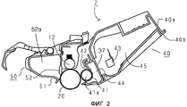
На фиг.2 представлено в увеличенном масштабе сечение картриджа.Figure 2 presents an enlarged scale section of the cartridge.
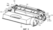
На фиг.3 показано перспективное изображение, иллюстрирующее конструкцию рамы технологического картриджа.Figure 3 shows a perspective image illustrating the design of the frame of the process cartridge.
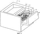
На фиг.4 представлено перспективное изображение основного узла в состоянии, в котором открываемая и закрываемая дверцы открыты.Figure 4 presents a perspective image of the main node in a state in which the opening and closing doors are open.
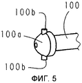
На фиг.5 представлено перспективное изображение приводного вала основного узла.Figure 5 presents a perspective image of the drive shaft of the main node.
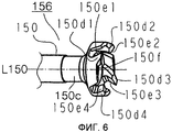
На фиг.6 представлено перспективное изображение свободной концевой части соединительного элемента.Figure 6 presents a perspective image of the free end portion of the connecting element.
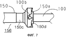
На фиг.7 представлена иллюстрация, демонстрирующая состояние, в котором соединительный элемент и приводной вал соединены друг с другом.7 is an illustration showing a state in which a connecting member and a drive shaft are connected to each other.
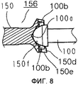
На фиг.8 представлено сечение, иллюстрирующее состояние, в котором соединительный элемент и приводной вал соединены друг с другом.Fig. 8 is a sectional view illustrating a state in which a connecting member and a drive shaft are connected to each other.
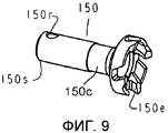
На фиг.9 представлено перспективное изображение воспринимающего вращающую силу элемента, который является частью соединительного элемента.Fig. 9 is a perspective view of a rotational force sensing member that is part of a connecting member.
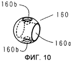
На фиг.10 представлено перспективное изображение сферической части, которая является составной частью соединительного элемента.Figure 10 presents a perspective image of a spherical part, which is an integral part of the connecting element.
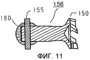
На фиг.11 представлено сечение соединительного элемента.11 shows a cross section of a connecting element.
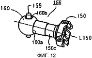
На фиг.12 представлено перспективное изображение соединительного элемента.On Fig presents a perspective image of the connecting element.
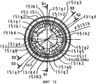
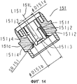
На фиг.13 представлена иллюстрация фланца барабана.13 is an illustration of a drum flange.
На фиг.14 представлено сечение, проведенное по линии S2-S2, показанной на фиг.13.On Fig presents a section drawn along the line S2-S2, shown in Fig.13.
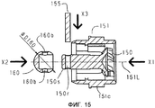
На фиг.15 представлено сечение, иллюстрирующее процесс, во время которого осуществляют сборку воспринимающего вращающую силу элемента во фланец барабана, в сечении вдоль линии Sl-Sl, показанной на фиг.13.Fig. 15 is a sectional view illustrating a process during which the rotational force receiving member is assembled into the drum flange, in section along the Sl-Sl line shown in Fig. 13.
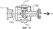
На фиг.16 представлено сечение, иллюстрирующее процесс, во время которого муфту крепят к фланцу барабана, в сечении вдоль линии Sl-Sl, показанной на фиг.13.On Fig presents a section illustrating the process during which the clutch is attached to the flange of the drum, in section along the line Sl-Sl, shown in Fig.13.
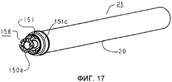
На фиг.17 представлено перспективное изображение блока, на виде с приводной стороны.On Fig presents a perspective image of the block, in a view from the drive side.
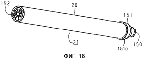
На фиг.18 представлено перспективное изображение блока, на виде с неприводной стороны.On Fig presents a perspective image of the block, in a view from the non-drive side.
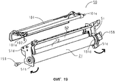
На фиг.19 представлено перспективное изображение, иллюстрирующее процесс разборки блока светочувствительного элемента.On Fig presents a perspective image illustrating the process of disassembling the block of the photosensitive element.
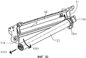
На фиг.20 представлено перспективное изображение, иллюстрирующее процесс разборки блока светочувствительного элемента.On Fig presents a perspective image illustrating the process of disassembling the block of the photosensitive element.
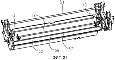
На фиг.21 представлено перспективное изображение, иллюстрирующее процесс разборки блока светочувствительного элемента.On Fig presents a perspective image illustrating the process of disassembling the block of the photosensitive element.
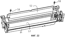
На фиг.22 представлено перспективное изображение, иллюстрирующее процесс разборки блока светочувствительного элемента.On Fig presents a perspective image illustrating the process of disassembling the block of the photosensitive element.
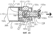
На фиг.23 представлено сечение, иллюстрирующее способ снятия соединительного элемента непосредственно с блока барабана.On Fig presents a cross section illustrating a method of removing the connecting element directly from the drum unit.
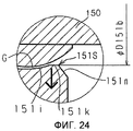
На фиг.24 представлен в увеличенном масштабе частый разрез части с проемом, показанной на фиг.23.On Fig presents on an enlarged scale a frequent section of the part with the opening shown in Fig.23.
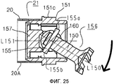
На фиг.25 представлено сечение, иллюстрирующее способ снятия соединительного элемента непосредственно с блока барабана.On Fig presents a cross section illustrating a method of removing the connecting element directly from the drum unit.
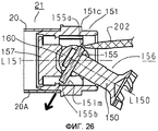
На фиг.26 представлено сечение, иллюстрирующее способ снятия соединительного элемента непосредственно с блока барабана.On Fig presents a section illustrating a method of removing the connecting element directly from the drum unit.
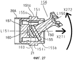
На фиг.27 представлено сечение, иллюстрирующее способ снятия соединительного элемента непосредственно с блока барабана.On Fig presents a cross section illustrating a method of removing the connecting element directly from the drum unit.
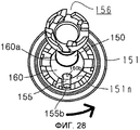
На фиг.28 представлено перспективное изображение, которое является пространственной иллюстрацией состояния согласно фиг.27.On Fig presents a perspective image, which is a spatial illustration of the state according to Fig.
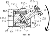
На фиг.29 представлено сечение, иллюстрирующее способ снятия соединительного элемента непосредственно с блока барабана.On Fig presents a cross section illustrating a method of removing the connecting element directly from the drum unit.
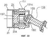
На фиг.30 представлено сечение, иллюстрирующее способ снятия соединительного элемента непосредственно с блока барабана.On Fig presents a cross section illustrating a method of removing the connecting element directly from the drum unit.
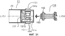
На фиг.31 представлено сечение, иллюстрирующее способ повторной сборки блока барабана.On Fig presents a cross section illustrating a method of reassembling a drum unit.
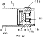
На фиг.32 представлено сечение, иллюстрирующее способ повторной сборки блока барабана.Fig. 32 is a sectional view illustrating a method for reassembling a drum unit.
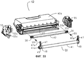
На фиг.33 представлено перспективное изображение, иллюстрирующее способ разборки блока барабана.33 is a perspective view illustrating a method for disassembling a drum unit.
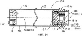
На фиг.34 представлено перспективное изображение, иллюстрирующее способ повторной сборки блока барабана.Fig. 34 is a perspective view illustrating a method for reassembling a drum unit.
Лучший способ осуществления изобретенияThe best way of carrying out the invention
Со ссылками на прилагаемые чертежи будут описаны варианты осуществления данного изобретения. Функция, материал, конфигурация, позиционные взаимосвязи и т.п. элементов, описываемых ниже, не являются ограничивающими данное изобретение, если не оговорено иное. Что касается материала, конфигурации и т.п. элементов, описанных один раз, то они применимы и к последующим описаниям, если не оговорено иное.With reference to the accompanying drawings, embodiments of the present invention will be described. Function, material, configuration, positional relationships, etc. the elements described below are not limiting of this invention, unless otherwise specified. As for the material, configuration, etc. elements described once, they apply to subsequent descriptions, unless otherwise specified.
Вариант осуществленияOption exercise
Общая компоновкаGeneral layout
На фиг.1 представлено сечение основного узла 1 устройства формирования изображения (основного узла) и технологического картриджа 2 (картриджа) устройства формирования изображения в варианте осуществления данного изобретения. На фиг.2 представлено в увеличенном масштабе сечение картриджа 2. Теперь, со ссылками на фиг.1-2, будут описаны общая компоновка и процесс формирования изображения в устройстве формирования изображения в соответствии с данным вариантом осуществления.Figure 1 shows a cross section of the
Данное устройство формирования изображения представляет собой лазерный принтер, в котором используется метод электрофотографии, при этом картридж 2 устанавливают с возможностью снятия в основной узел 1. Когда картридж 2 устанавливают в основной узел 1, в верхней части картриджа 2 располагается экспонирующее устройство 3 (блок лазерного сканера). Нижняя часть картриджа 2 снабжена лотком 4 для листов, содержащим материал Р для записи информации (листовой материал), представляющий собой объект, на котором формируют изображение. Основной узел 1 снабжен предусмотренными вдоль направления подачи листового материала Р подбирающим валиком 5a, подающим валиком 5b, парой 5c подающих валиков, направляющей 6 переноса, зарядным валиком 7 переноса, подающей направляющей 8, фиксирующим устройством 9, парой 10 выпускных валиков, выпускным лотком 11 и т.д.This imaging device is a laser printer that uses the electrophotography method, and the
Процесс формирования изображенияImaging process
Теперь будет описан основной принцип процесса формирования изображения. В ответ на сигнал начала печати барабан 20 электрофотографического светочувствительного элемента (барабан) вращается в направлении, обозначенном стрелкой R1 с заданной окружной скоростью (технологической скоростью). С внешней поверхностью барабана 20 контактирует зарядный валик 12 (зарядное средство, средство обработки), на который подается напряжение смещения, и внешняя поверхность барабана 20 равномерно заряжается этим зарядным валиком 12.Now, the basic principle of the image forming process will be described. In response to the print start signal, the
Из экспонирующего устройства 3 выдается луч L лазера, модулированный соответственно последовательному электрическому цифровому сигналу пикселя информации изображения. Луч L лазера попадает внутрь картриджа 2 через экспозиционное окно 53 верхней поверхности картридж 2 для экспонирования внешней поверхности барабана 20, сканируемой этим лучом лазера. На внешней поверхности барабана 20 формируется электростатическое скрытое изображение, соответствующее информации изображения. Это электростатическое скрытое изображение визуализируется с получением изображения, проявленного тонером, с помощью проявителя Т (тонера) в блоке 40 проявочного устройства.From the exposure device 3, a laser beam L is output, modulated according to the serial electric digital signal of the image information pixel. The laser beam L enters the
Зарядный валик 12 находится в контакте с барабаном 20 и осуществляет электрическую зарядку барабана 20. Зарядный валик 12 вращается барабаном 20. Блок 40 проявочного устройства подает тонер в зону проявки барабана 20 для проявки скрытого изображения, сформированного на барабане 20.The charging
Блок 40 проявочного устройства подает тонер T, находящийся в камере 45 тонера, в камеру 44 подачи тонера за счет вращения перемешивающего элемента 43. Проявочный валик 41 (проявочное средство, средство обработки), который является несущим проявитель элементом, содержащим магнитный валик 41а (постоянный магнит), вращается, и на поверхности проявочного валика 41 формируется слой тонера, трибоэлектрически заряженный проявочным ножом 42. Тонер переносится на барабан 20 в соответствии со скрытым изображением, так что электростатическое скрытое изображение визуализируется с получением изображения, проявленного тонером. Проявочный нож 42 прикладывает трибоэлектрический заряд, регулируя количество тонера на периферийной поверхности проявочного валика 41.The developing
С другой стороны и в соответствии с синхронизацией выдачи луча L лазера листовой материал Р, содержащийся в нижней части основного узла 1, подается из лотка 4 для листов подбирающим валиком 5a, подающим валиком 5b и парой 5с подающих валиков. Листовой материал Р синхронизируется и подается в положение переноса между барабаном 20 и зарядным валиком 7 для переноса по направляющей 6 переноса. В положении переноса изображение, проявленное тонером, последовательно переносится на листовой материал Р с барабана 20.On the other hand, and in accordance with the timing of the output of the laser beam L, the sheet material P contained in the lower part of the
Листовой материал Р, на который перенесено изображение, проявленное тонером, отделяется от барабана 20 и подается к фиксирующему устройству 9 по подающей направляющей 8. Листовой материал P проходит через зону контакта, образованную между фиксирующим валиком 9a и прижимным валиком 9b, которые составляют фиксирующее устройство 9. Этот материал подвергается воздействию процесса фиксации посредством приложения давления и нагрева в зоне контакта, так что изображение, проявленное тонером, фиксируется на листовом материале Р. Листовой материал P, подвергшийся воздействию процесса фиксации изображения для изображения, проявленного тонером, подается к паре 10 выпускных валиков и выпускается в выпускной лоток 11.The sheet material P onto which the toner developed image is transferred is separated from the
С другой стороны, остаточный тонер на внешней поверхности барабана 20 удаляется очищающим ножом 52 (очищающим средством, средством обработки) после переноса, и барабан 20 используется для следующей операции формирования изображения, которая начинается вместе с операцией электрической зарядки. Израсходованный тонер, удаленный с барабана 20, хранится в камере 52а израсходованного тонера блока 50 светочувствительного элемента.On the other hand, the residual toner on the outer surface of the
Зарядный валик 12, проявочный валик 41, очищающий нож 52 и т.п. являются средствами обработки, приводимыми в действие на барабане 20, соответственно.Charging
Конструкция рамы технологического картриджаProcess cartridge frame design
На фиг.3 представлено перспективное изображение, иллюстрирующие конструкцию рамы картриджа 2.Figure 3 presents a perspective image illustrating the design of the frame of the
Конструкция рамы картриджа 2 будет описана со ссылками на фиг.2 и фиг.3.The design of the frame of the
Как показано на фиг.2, барабан 20, зарядный валик 12 и очищающий нож 52 установлены на раму 51 барабана, составляя единый блок 50 светочувствительного барабана.As shown in FIG. 2, the
С другой стороны, блок 40 проявочного устройства образован камерой 45 тонера, которая содержит тонер, и вмещающей тонер камерой 40а, которая образует камеру 44 подачи тонера, и крышкой 40b.On the other hand, the developing
Вмещающая тонер камера 40а и крышка 40b соединены в единое целое друг с другом с помощью такого средства, как сварка.The toner holding chamber 40a and the
Как показано на фиг.3, свободный конец рычажной части 55а, выполненной на боковой крышке 55, предусмотренной на каждом конце относительно продольного направления (осевого направления проявочного валика 41) блока 40 проявочного устройства, снабжен круглым отверстием 55b под вращение, выполненное параллельным проявочному валику 41.As shown in FIG. 3, the free end of the lever portion 55a formed on the
Рама 51 барабана имеет отверстие 51а для сцепления, предназначенное для приема элемента 54 соединения, соосного с отверстием 55b для вращения, когда рычажная часть 55а вставлена в заданном положении рамы 51 барабана.The
Блок 50 светочувствительного элемента и блок 40 проявочного устройства соединены с возможностью поворота друг относительно друга с помощью элемента 54 соединения за счет вставления элемента 54 соединения сквозь оба отверстия - отверстие 55b для вращения и отверстие 51а для сцепления. При этом цилиндрическая пружина 46 сжатия, установленная на базовую часть рычажной части 55а, упирается в раму 51 барабана, отжимая блок 40 проявочного устройства книзу.The
За счет этого проявочный валик 41 (фиг.2) надежно прижимается к барабану 20.Due to this, the developing roller 41 (figure 2) is firmly pressed against the
На противоположные концы проявочного валика 41 установлены распорные элементы (не показаны), так что проявочный валик поддерживается с заданными интервалами от барабан 20.Spacer elements (not shown) are installed at opposite ends of the developing
Способ передачи вращающей силы на технологический картриджMethod for transmitting rotational force to a process cartridge
На фиг.4 представлено перспективное изображение внутренней части основного узла с открытой дверцей 140 для картриджа (дверцей основного узла). Картридж 2 не установлен.Figure 4 presents a perspective image of the inner part of the main node with the
Теперь со ссылками на фиг.4 будет описан способ передачи вращающей силы на картридж 2.Now, with reference to FIG. 4, a method of transmitting a rotational force to the
Как показано на фиг.4, в основном узле 1 предусмотрена рельсовая направляющая 130 для установки и снятия картриджа, а картридж 2 устанавливают внутрь основного узла 1 по этой рельсовой направляющей 130.As shown in figure 4, in the
В этом случае приводной вал 100 основного узла 1 и соединительный элемент 150 (фиг.3) в качестве передающей вращающую силу части картриджа 2 соединяются друг с другом во взаимосвязи с операцией установки картриджа 2.In this case, the
За счет этого барабан 20 воспринимает от основного узла 1 вращающую силу для вращения.Due to this, the
1) Приводной вал 1001) Drive
На фиг.5 представлено перспективное изображение приводного вала 100 со стороны основного узла.Figure 5 presents a perspective image of the
Приводной вал 100 соединен с передаточным средством привода, таким как не показанная зубчатая передача, предусмотренным в основном узле 1, с не показанным электродвигателем.The
Свободная концевая часть 100a приводного вала 100 имеет по существу полусферическую форму и имеет передающие вращающую силу пальцы в качестве прикладывающих вращающую силу частей 100b.The free end portion 100a of the
2) Соединительный элемент2) Connecting element
В состоянии, в котором картридж 2 установлен с возможностью снятия в основной узел 1, соединительный элемент 156 имеет функцию восприятия вращающей силы от основного узла для вращения барабана 20.In a state in which the
Как показано на фиг.11 и фиг.12, этот соединительный элемент 156 имеет воспринимающий вращающую силу элемент 150, который имеет в своей свободной концевой части воспринимающую вращающую силу часть 150е (150el-150e4) для восприятия вращающей силы.As shown in FIGS. 11 and 12, this connecting
Кроме того, он имеет сферическую часть 160 (сферический элемент), установленную за счет проходящего насквозь пальца 155 сквозь заднюю концевую часть воспринимающего вращающую силу элемента 150.In addition, it has a spherical part 160 (spherical element) mounted by passing through the
На фиг.6 представлено перспективное изображение воспринимающего вращающую силу элемента 150. Материал соединительного элемента 150 представляет собой полимерный материал, такой как полиацетель, поликарбонат и полифениленсульфид (ППС) или аналогичный материал.6 is a perspective view of a rotational
Вместе с тем, чтобы увеличить жесткость воспринимающего вращающую силу элемента 150, в полимерном материале возможно смешение стекловолокон, углеродных волокон и/или аналогичных волокон соответственно требуемой нагрузке в виде крутящего момента.However, in order to increase the rigidity of the rotational
В случае, когда смешивают такой материал, можно увеличить жесткость воспринимающего вращающую силу элемента 150.In the case when such material is mixed, it is possible to increase the rigidity of the rotational
Жесткость можно дополнительно увеличить путем введения металла в полимерный материал, при этом весь воспринимающий вращающую силу элемент 150 можно изготовить из металла и т.п.The stiffness can be further increased by introducing the metal into the polymeric material, while the entire rotational
Свободный конец передающего вращающую силу элемента 150 снабжен множеством воспринимающих привод выступов 150d (150d1-150d4).The free end of the rotational
Кроме того, воспринимающий привод выступ 150d (150d1-150d4) снабжен воспринимающей вращающую силу частью 150e (150e1-150e4), наклоненную относительно оси L150 воспринимающего вращающую силу элемента 150.In addition, the
Кроме того, внутри воспринимающего привод выступа 150d1-150d4 предусмотрена воронкообразная поверхность 150f.In addition, a funnel-shaped
3) Состояние соединения между приводным валом 100 и муфтовым элементом 1563) The condition of the connection between the
На фиг.7 представлена иллюстрация, демонстрирующая состояние, в котором воспринимающий вращающую силу элемент 150 соединительного элемента 156 и приводной вал 100 соединены друг с другом. На фиг.8 представлено сечение, иллюстрирующее состояние, в котором воспринимающий вращающую силу элемент 150 и приводной вал 100 соединены друг с другом.7 is an illustration showing a state in which the rotational
Теперь со ссылками на фиг.7 и фиг.8 будет описано состояние соединения между приводным валом 100 и воспринимающим вращающую силу элементом 156.Now, with reference to FIGS. 7 and 8, the state of the connection between the
Передающий вращающую силу палец 100b приводного вала 100 сцеплен с воспринимающей вращающую силу частью 150e (150e1-150e4).The rotational
Хотя это и не показано на фиг.7, передающий вращающую силу палец 100b на задней стороне также сцеплен с воспринимающей вращающую силу частью 150e.Although not shown in FIG. 7, the rotational
Кроме того, свободная концевая часть 100а приводного вала 100 находится в контакте с выемкой 150f воспринимающего вращающую силу элемента 150. За счет вращения приводного вала 100 вращающая сила передается на воспринимающую вращающую силу часть 150e от передающего вращающую силу пальца 100b.In addition, the free end portion 100a of the
Кроме того, за счет наклона воспринимающей вращающую силу части 150e относительно оси L150 воспринимающего вращающую силу элемента 150 этот воспринимающий вращающую силу элемент 150 и приводной вал 100 притянуты друг к другу, а между свободной концевой частью 100а и выемкой 150f имеется гарантированный контакт, так что достигается гарантированная передача вращающей силы.Furthermore, by tilting the rotational
4) Соединительный элемент 156 и соединительная часть4) Connecting
На фиг.9 представлено перспективное изображение, иллюстрирующее воспринимающий вращающую силу элемент 150, а на фиг. 10 представлено перспективное изображение, иллюстрирующее сферическую часть 160.FIG. 9 is a perspective view illustrating a rotational
На фиг.11 представлено сечение соединительного элемента 156, а на фиг.12 представлено перспективное изображение соединительного элемента 156.Figure 11 presents a cross section of the connecting
Как показано на фиг.9, конец стороны, противоположной воспринимающей вращающую силу части 150е воспринимающего вращающую силу элемента 150, снабжен сквозным отверстием 150r.As shown in FIG. 9, the end of the side opposite the rotational
Как показано на фиг.10, сферическая часть 160, соединенная с воспринимающим вращающую силу элементом 150, имеет по существу сферическую форму и снабжена воспринимающим вращающую силу элементом 150 и отверстием для принятия пальца 155, как будет описано ниже.As shown in FIG. 10, the
Отверстие 160a, закрытое на одном конце, принимает конец 150s воспринимающего вращающую силу элемента 150. Сквозное отверстие 160b - вместе с отверстием 160а - принимает палец 155, что будет описано ниже.A
Как показано на фиг.11 и 12, воспринимающий вращающую силу элемент 150 вставлен в сферическую часть 160, а палец 155 вставляют в состоянии, в котором сквозное отверстие 150r и сквозное отверстие 160b выровнены друг с другом.As shown in FIGS. 11 and 12, the rotational
В этом варианте осуществления воспринимающий вращающую силу элемент 150 и отверстие 160a сцеплены по скользящей посадке.In this embodiment, the rotational
Палец 155 и сквозное отверстие 150r сцеплены по скользящей посадке.The
Палец 155 и сквозное отверстие 160b сцеплены по прессовой посадке.The
Соответственно, палец 155 и сферическая часть 160 соединены в единое целое.Accordingly, the
Часть, обеспечиваемая соединением между воспринимающим вращающую силу элементом 150 и цилиндрической частью 160, представляет собой соединительный элемент 156.The part provided by the connection between the rotational
Когда вращающая сила воспринимается от приводного вала 100, воспринимающий вращающую силу элемент поворачивается вокруг оси L150, а сквозное отверстие 150r сцепляется с пальцем 155.When a rotational force is received from the
Более конкретно, вращающая сила, передаваемая от основного узла 1, преобразуется в силу для вращения пальца 155 вокруг оси L150 вращения посредством воспринимающего вращающую силу элемента 150.More specifically, the rotational force transmitted from the
5) Передача вращающей силы на барабан 20 от соединительного элемента 1565) The transmission of rotational force to the
На фиг.13 представлено изображение, иллюстрирующее фланец 151 барабана, а на фиг. 14 представлено сечение, проведенное вдоль линии S2-S2, показанной на фиг. 13.13 is a view illustrating a
На фиг.15 представлено сечение, проведенное вдоль линии S1-S1, показанной на фиг.13, иллюстрирующее процесс, во время которого осуществляют сборку воспринимающего вращающую силу элемента 150 во фланец 151. На фиг.16 представлено сечение, проведенное вдоль линии S1-S1, показанной на фиг.13, иллюстрирующее процесс, во время которого осуществляют крепление воспринимающего вращающую силу элемента 150 к фланцу 151.FIG. 15 is a sectional view taken along line S1-S1 shown in FIG. 13 illustrating a process during which the rotational
На фиг.17 представлено перспективное изображение блока 21 электрофотографического светочувствительного барабана (блока барабана), на виде с приводной стороны (со стороны воспринимающего вращающую силу элемента 150).On Fig presents a perspective image of the
На фиг.18 представлено схематическое перспективное изображение блока 21 барабана, на виде с не приводной стороны (продольно противоположной воспринимающему вращающую силу элемента 150).On Fig presents a schematic perspective view of the
Теперь со ссылками на фиг.13 и фиг.14 будет описан пример фланца 151 барабана (фланца), на который устанавливают воспринимающий вращающую силу элемент 150.Now with reference to Fig.13 and Fig.14 will be described an example of a
Фланец 151, на виде со стороны приводного вала 100, изображен на фиг.13.The
Проем 151g (151g1-151g4), показанный на фиг.13, представляет собой паз, проходящий в направлении оси вращения фланца 151.The opening 151g (151g1-151g4) shown in FIG. 13 is a groove extending in the direction of the axis of rotation of the
Когда воспринимающий вращающую элемент 150 устанавливают на фланец 151, палец 155 принимается любыми двумя из этих проемов 151g1-151g4.When the receiving
Расположенная выше по часовой стрелке сторона проемов 151g1-151g4 снабжена передающей вращающую силу поверхностью (воспринимающей вращающую силу частью) 151h (151h1-151h4).The clockwise upstream side of the openings 151g1-151g4 is provided with a rotational force transmitting surface (rotational force receiving part) 151h (151h1-151h4).
Когда вращающая сила передается на фланец 151 от пальца 155, этот палец 155 и передающая вращающую силу поверхность 151h контактируют друг с другом.When the rotational force is transmitted to the
Кроме того, рядом с центральной осью L151 фланца 151 предусмотрена выемка (полость) 151f. Выемка 151f обеспечивает полость, окруженную цилиндрической поверхностью 151j (151j1-151j4), стопорящей частью 151i (151il-151i4), которая является регулирующей частью, и проемом 151k (151k1-151k4). Цилиндрическая поверхность 151j (151j1-151j4) представляет собой по существу цилиндрическую поверхность, которая соосна с осью l151 и которая примыкает к проему 151g и имеет диаметр D151a.In addition, a recess (cavity) 151f is provided near the central axis L151 of the
Стопорящая часть 151i (151i1-151i4) имеет по существу полусферическую поверхность, которая гладко продолжается цилиндрической поверхностью 151j и имеет радиус SR151.The locking
Проем 151k (151k1-151k4) находится на обращенной к приводному валу 100 стороне стопорящей части 151i и имеет диаметр D151b.The
Более конкретно, проем 151k имеет первую поверхность регулирующей части, которая продолжается от стопорящей части 151i (регулирующей части) и которая проходит в направлении от соединительного элемента 156 к свободному концу воспринимающего вращающую силу элемента 150 относительно продольного направления барабана 20.More specifically, the
Кроме того, соотношение между ними и наружным размером D160 сферического элемента 160 является следующим (фиг. 14, фиг. 15):In addition, the ratio between them and the outer dimension D160 of the
D151b < D160 < D151a = 2×SR15l.D151b <D160 <D151a = 2 × SR15l.
Хотя сферический элемент 160 можно вставлять в выемку 151f с зазором G (фиг.24), его перемещение к проему 151k в направлении оси L151 предотвращено.Although the
За счет этого предотвращения сферический элемент 160 (соединительного элемента 156) неотделим от фланца 151 (технологического картриджа 2) при нормальных условиях.Due to this prevention, the spherical element 160 (connecting element 156) is inseparable from the flange 151 (process cartridge 2) under normal conditions.
Более конкретно, фланец 151 установлен на конец барабана 20, а соединительный элемент 156 установлен на фланец 151.More specifically, the
Для установки соединительного элемента 156 фланец 151 снабжен регулирующей частью (стопорящей частью 151i), проходящий по внутренней периферийной поверхности фланца 151. Эта регулирующая часть (стопорящая часть 151i) имеет зазор G относительно сферической части 160 и имеет конфигурацию, которая ближе к конфигурации поверхности сферической части 160 воспринимающего вращающую силу элемента 150, чем плоскость, которая перпендикулярна продольному направлению барабана 20 и которая проходит через центр сферической части 160.To install the connecting
Теперь, со ссылками на фиг.15 и 16, будет описан процесс сборки воспринимающего вращающую силу элемента 150 на фланец 151 и крепления к нему. Концевую часть 150s вставляют в направлении стрелки X1 во фланец 151.Now, with reference to FIGS. 15 and 16, the process of assembling the rotational
Затем сферическую часть 160 помещают поверх концевой части 150s в направлении, обозначенном стрелкой X2.Then, the
Кроме того, сквозные отверстия 160b сферической части 160 и сквозное отверстие 150r концевой части 150s выравнивают друг с другом, а после этого вставляют в них палец 155 в направлении стрелки X3.In addition, the through
Палец 155 вставляют через сквозные отверстия 160b и сквозное отверстие 150r.The
Поскольку внутренний диаметр сквозных отверстий 160b и сквозного отверстия 150r меньше, чем диаметр пальца 155, между пальцем 155 и сквозными отверстиями 160b возникает сила трения. В этом варианте осуществления натяг составляет около 50 микрометров.Since the inner diameter of the through
За счет этого, во время обычного использования предотвращается отклонение пальца 155, а соединительный элемент 150 образуется соединением между воспринимающим вращающую силу элементом 150 и сферической частью 160.Due to this, during normal use, the deviation of the
Кроме того, соединительный элемент 156 перемещается в направлении X4, а сферическая часть 160 вступает в контакт со стопорящей частью 151i или приближается к ней.In addition, the connecting
Затем стопорящий элемент 157 вставляют в направлении, обозначенном стрелкой X4, и крепят к фланцу 151.Then, the locking
Поскольку для сферической части 160 предусмотрен люфт (зазор), соединительный элемент 156 может изменять ориентацию.Since backlash (clearance) is provided for the
Теперь со ссылками на фиг.17 и фиг.18 будут описаны конструкции блока 21 барабана.Now, with reference to FIG. 17 and FIG. 18, the structures of the
Фланец 151, который имеет соединительный элемент 156, крепится к концевой стороне барабана 20 таким образом, что воспринимающий привод выступ 150d открыт снаружи.A
Кроме того, фланец 152 барабана на не приводной стороне крепится к другой концевой стороне барабана 20.In addition, the
Способом крепления может быть обжатие, склеивание, сварка и т.п.The fixing method can be crimping, gluing, welding, etc.
В состоянии, в котором приводная сторона блока 21 барабана поддерживается опорным элементом 158 (фиг.3, фиг.19), а его не приводная сторона поддерживается с возможностью вращения поддерживающим блок барабана пальцем 159 (фиг.3), блок 21 барабана поддерживается с возможностью вращения рамой 51 барабана (фиг.3). Как описано выше, вращающая сила, передаваемая от электродвигателя (не показан) основного узла 1, вращает приводной вал 100 с помощью передающего привод средства, такого как зубчатое колесо (не показано) основного узла 1.In a state in which the drive side of the
Эта вращающая сила передается на картридж 2 через воспринимающий вращающую силу элемент 150 соединительного элемента 156.This rotational force is transmitted to the
Кроме того, вращающая сила передается через палец 155 от воспринимающего вращающую силу элемента 150 на фланец 151 через палец 155 для приложения вращающей силы к барабану 20, прикрепленному к фланцу 151 как единое целое с ним.In addition, the rotational force is transmitted through the
Внешняя периферия фланца 151 снабжена косозубым зубчатым колесом 151c, сформованным как единое целое с фланцем 151.The outer periphery of the
Это зубчатое колесо 151c передает вращающую силу, воспринимаемую от приводного вала 100 воспринимающим вращающую силу элементом 150, на проявочный валик 41 (фиг.2).This
Более конкретно, внешняя часть, располагающаяся напротив стопорящей части, которая является регулирующей 151i фланца 151, снабжена косозубым зубчатым колесом 151с, и это зубатое колесо передает вращающую силу, воспринимаемую от основного узла 1 воспринимающей вращающую силу частью, на проявочный валик 41.More specifically, the outer part opposite the locking part, which is the regulating 151i of the
Способ повторного изготовления картриджаCartridge Re-Manufacturing Method
В картридже 2, установленном и используемом в основном узле 1 устройства, тонер Т, содержащийся в камере 45 тонера, расходуется при повторении формирования изображения.In the
Когда тонер Т расходуется до такое степени, что формирование изображения, качество которого удовлетворяет пользователя картриджа 2, оказывается невозможным, это приводит к утрате товарной значимости картриджа 2.When the toner T is consumed to such an extent that image formation, the quality of which satisfies the user of the
Ввиду этого предусматривается, например, средство (не показано) для обнаружения остающегося количества тонера картриджа 2, а схема управления основного узла (не показана) сравнивает обнаруженное остающееся количество с заданным порогом для выдачи прогноза срока службы картриджа и/или предупреждения о сроке службы картриджа.In view of this, for example, means are provided (not shown) for detecting the remaining amount of toner of the
Когда обнаруженное остаточное количество меньше, чем порог, индикаторная часть (не показана) отображает прогноз срока службы или предупреждение о сроке службы картриджа 2.When the detected residual amount is less than the threshold, an indicator part (not shown) displays a life expectancy or a warning about the life of the
За счет этого пользователь получает возможность подготовить сменный картридж 2, а вследствие этого поддерживается качество выходных изображений.Due to this, the user is able to prepare a
Использованные технологические картриджи 2 накапливают и проводят их чистку, замену деталей и т.д., а также засыпают в них свежий тонер.
За счет этого осуществляется повторное изготовление для повторного использования.Due to this, re-manufacturing for reuse is carried out.
Теперь будет описан способ повторного изготовления использованного картриджа.A method for re-manufacturing a used cartridge will now be described.
В данном случае, очистку проводят, например, путем всасывания воздуха, продувки воздуха, влажной очистки, протирки и т.п.In this case, the cleaning is carried out, for example, by suction of air, blowing air, wet cleaning, wiping, etc.
(i) Этап отделения блоков друг от друга(i) The step of separating the blocks from each other
Когда элемент 54 соединения, который соединяет блок 50 светочувствительного элемента и блок 40 проявочного устройства, поворачивающиеся друг относительно друга, вытаскивают, блок 40 проявочного устройства и блок 50 светочувствительного элемента отделяются друг от друга (фиг.3).When the
(ii) Разборка, очистка, замена деталей, повторная сборка блока 50 светочувствительного элемента(ii) Dismantling, cleaning, replacing parts, reassembling the
На фиг.19-22 представлены перспективные изображения, иллюстрирующие процессы разборки блока 50 светочувствительного элемента.On Fig.19-22 presents perspective images illustrating the processes of disassembly of the
После отделения блока 50 светочувствительного элемента и блока 40 проявочного устройства друг от друга проводят разборку, очистку, замену деталей, повторную сборку блока 50 со светочувствительным поверхностным слоем.After separating the
Эти операции будут описаны ниже.These operations will be described below.
Сначала со ссылками на фиг.19 будет описана разборка выступающего элемента 101 и прижимной пружины 102.First, with reference to FIG. 19, disassembly of the protruding
Вальную часть 101а выступающего элемента 101 для экранирования и защиты от света барабана 20 снимают вместе с прижимной пружиной 102 с U-образной опорной части 51d рамы 51 барабана.The shaft portion 101a of the protruding
Теперь со ссылками на фиг.20 будет описан способ снятия блока 21 барабана.Now, with reference to FIG. 20, a method of removing the
Блок 21 барабана поддерживается опорным элементом 158 и поддерживающим блок барабана пальцем 159, предусмотренными на соответствующих концах блока 50 светочувствительного элемента (рамы 51 барабана).The
Когда вытаскивают палец 159, неприводная сторона (сторона с пальцем) блока 21 барабана расцепляется.When the
Стенку 51b неприводной стороны рамы 51 барабана открывают в продольном направлении наружу, и одновременно с этим опорный элемент 158, закрепленный на стенке 51с приводной стороны рамы 51 барабана как единое целое с ней, открывается в продольном направлении наружу на приводной стороне.The
Эти направления обозначены стрелками на фиг.19.These directions are indicated by arrows in FIG.
Затем блок 21 барабана поворачивают в направлении, обозначенном стрелкой X201, вокруг приводной стороны блока 21 барабана.Then, the
Его поворачивают, пока фланец 152 барабана неприводной стороны (фиг.18) не перестанет перекрываться со стенкой 51b неприводной стороны относительно осевого направления (направлению стрелки X202) блока 21 барабана, и затем блок 21 барабана легко вытаскивают в направлении, обозначенном стрелкой X202.It is rotated until the non-drive side drum flange 152 (Fig. 18) ceases to overlap with the
Теперь со ссылками на фиг.21 будет описано удаление израсходованного тонера и снятие зарядного валика 12.Now, with reference to FIG. 21, the removal of the consumed toner and the removal of the
Когда блок 21 барабана снимают, между очищающим ножом 52 и листом 56 для предотвращения утечки израсходованного тонера, установленным на раму 51 барабана, образуется удлиненный проем 57 для сбора израсходованного тонера.When the
За счет этого удаление израсходованного тонера, хранимого в камере 52а израсходованного тонера (фиг.2) рамы 51 барабана, может быть достигнуто с помощью проема 57 для сбора израсходованного тонера.Due to this, the removal of the spent toner stored in the
Это удаление осуществляется, например, путем всасывания воздуха, его продувки, влажной очистки, протирки.This removal is carried out, for example, by suction of air, its purge, wet cleaning, wiping.
Для снятия зарядного валика 12 снимают вал валика в направлении, обозначенном стрелкой, с опор 13 зарядного валика на стороне рамы барабана, которая поддерживает противоположные концы вала валика.To remove the charging
В состоянии, в котором зарядный валик 12 снят, осуществляют удаление израсходованного тонера, избегая загрязнения зарядного валика 12 и повреждения зарядного валика 12 во время этого удаления.In the state in which the
Снятие очищающего ножа 52 осуществляют путем удаления двух винтов 58, которые крепят очищающий нож 52 к раме 51 барабана.Removing the cleaning
(iii) Снятие и разборка соединительного элемента 156 (1)(iii) Removing and disassembling connector 156 (1)
В этом варианте осуществления воспринимающий вращающую силу элемент 150 и палец 155 соединительного элемента 156 выполнены из металла, чтобы достичь высокого качества изображения.In this embodiment, the rotational
Поскольку они выполнены из металла, долговечность является превосходной, и можно осуществлять повторное использование, вследствие чего желательно снимать их и использовать повторно. При осуществлении способа снятия соединительного элемента 156 способ изготовления блока 21 барабана, описанный выше, воплощают в обратном порядке.Since they are made of metal, the durability is excellent and reuse can be carried out, whereby it is desirable to remove and reuse them. In the method for removing the connecting
Иными словами, барабан 20 снимают с блока 21 барабана и затем материал 158 стопорящей части (фиг.16) отделяют от фланца 151.In other words, the
Затем вытаскивают палец 155 из соединительного элемента 156.Then pull the
За счет этого воспринимающий вращающую силу элемент 150 и сферическую часть 160 можно отделить друг от друга.Due to this, the rotational
Палец 155 и воспринимающий вращающую силу элемент 150 повторно используются по меньшей мере один раз (не показано).The
(iv) Снятие и разборка соединительного элемента 156 (2)(iv) Removing and disassembling connector 156 (2)
В качестве другого способа возможно снятие соединительного элемента 156 непосредственно с блока 21 барабана.As another method, it is possible to remove the connecting
В этом случае, поскольку операция отделения барабана 20 и стопорящего элемента 157 друг от друга необязательна, эффективность работы оказывается превосходной.In this case, since the operation of separating the
Теперь будет описан способ снятия соединительного элемента 156 непосредственно с блока 21 барабана.A method for removing the connecting
На фиг.23 представлено сечение, иллюстрирующее способ снятия соединительного элемента 156 непосредственно с блока 21 барабана. Это сечение является сечением по линии S2-S2, показанной на фиг.13.On Fig presents a cross section illustrating a method of removing the connecting
На фиг.24 представлен подробный вид части с проемом 151k (части, обведенной кружком), показанной на фиг. 23.On Fig presents a detailed view of the part with the
Поскольку фланец 151 имеет зубчатое колесо 151c, оно обычно выполнено из полимерного материала с высокой способностью к скольжению, такого как полиацеталь.Since the
Поскольку сферическая часть 160 совершает качания в выемке 151f аналогичным образом, она тоже выполнена из полимерных элементов, например из полиацеталя. Более конкретно, сферическая часть 160 и фланец 151 (регулирующая часть, обозначенная позицией 151S, или стопорящая часть 151i) выполнены из полимерного материала.Since the
Как описано выше внешний размер D160 сферической части 160 больше, чем диаметр D151b проема 151k, и поэтому во время использования сферическая часть 160 (соединительного элемента 156) обычно не отделяется от фланца 151 (технологического картриджа 2).As described above, the outer dimension D160 of the
Проем 151k продолжается вместе со стопорящей частью 151i и наклоняется от соединительного элемента 156 (сферической части 160).The
Более детально, в этом варианте различие между внешним размером D160 сферической части 160 и диаметром D151b проема 151k составляет приблизительно 0,4 мм. Вместе с тем, поскольку фланец 151 и сферическая часть 160 выполнены из полимерного материала, они относительно легко деформируются в соответствии с внешней силой.In more detail, in this embodiment, the difference between the outer dimension D160 of the
Поэтому они деформируются, вследствие чего и оказывается возможным пропускание сферической части 160.Therefore, they are deformed, as a result of which it is possible to transmit the
Следовательно, соединительный элемент 156 можно извлекать из фланца 151.Therefore, the connecting
Сначала с гарантией удерживают элементы, не являющиеся воспринимающим вращающую силу элементом 150, блока 21 барабана, т.е. барабан 20 и фланец 151.At first, elements that are not sensitive to the rotational force of the
Затем, зажимая ведомую часть 150а и соединительную часть 150c, которые имеют воспринимающую вращающую силу часть 150е, зажимающим инструментом 201, таким как плоскогубцы или щипцы (средство с рифлением, которое использует соединительную часть 150с на фиг.23) (этап захватывания), можно вытащить их в направлении (направлении, обозначенном стрелкой X231) оси L150.Then, clamping the driven portion 150a and the connecting
За счет этого сферическая часть 160 контактирует со стопорящей частью 151i.Due to this, the
Кроме того, когда усилие вытягивания увеличивается, внешний размер D160 сферической части 160 уменьшается, так что стопорящая часть 151i, проем 151k и скошенная поверхность 151n фланца 151 деформируется наружу в радиальном направлении от оси L151 фланца 151 (направлении, обозначенном стрелкой на фиг. 24).Furthermore, when the pulling force increases, the outer dimension D160 of the
Скошенная поверхность 151n фланца 151 проходит к проему 151k и наклонена от соединительного элемента 156 к стороне свободного конца соединительного элемента 156, который находится на стороне ведомой части относительно осевого направления L151.The
Скошенная поверхность 151n представляет собой часть второй поверхности регулирующей части 151S.The
Более конкретно, скошенная поверхность 151n наклонена от проема 151k, который является первой поверхностью стопорящей части 151i, которая является регулирующей частью 151S, и проходит от соединительного элемента 156 к свободному концу воспринимающего вращающую силу элемента 150 относительно продольного направления барабана. Иными словами, сферическая часть 160, стопорящая часть которой является регулирующей частью 151S, которая выступает радиально внутрь от фланца 151, задает проем 151k и отгиб скошенной поверхности 151n и в момент, когда диаметр D151b проема 151k и внешний размер D160 сферической части 160 становятся одинаковыми, соединительный элемент 156 можно извлечь из фланца 151 (этап снятия).More specifically, the
Сила, необходимая при этом, составляет приблизительно 9-11 кгс (88-108 Н).The force required is approximately 9–11 kgf (88–108 N).
Для эффективного использования тяговой силы предпочтительно проводить операцию вытягивания в состоянии, в котором ось L151 фланца 151 и ось L150 воспринимающего вращающую силу элемента 150 выровнены друг с другом (позиционная взаимосвязь, показанная на фиг.23).For the efficient use of the traction force, it is preferable to carry out a drawing operation in a state in which the axis L151 of the
Гибкость регулирующей части фланца 151 (стопорящей части 151i, проема 151k, скошенной поверхности 15In) зависит от выемок 151q1-8, которые находятся в положениях снаружи в радиальном направлении фланца 151 барабана, как можно увидеть от регулирующей части 151S на фиг.13.The flexibility of the regulating part of the flange 151 (locking
Подробнее, когда выемки 151q велики, отделение происходит легко, а когда они малы, отделение затруднено.In more detail, when the
В этом варианте осуществления, связь размеров выбирают так, чтобы при нормальной эксплуатации функция удержания оказалась действенной и чтобы во время снятия его можно было осуществлять с помощью вышеописанной силы.In this embodiment, the dimensional relationship is chosen so that during normal operation the retention function is effective and that during removal it can be carried out using the above-described force.
При таком способе, как описано выше, соединительный элемент 156 может быть непосредственно снят с блока 21 барабана.With this method, as described above, the connecting
Соответственно, операция отделения барабана 20 и стопорящего элемента 157 друг от друга становится необязательной, и поэтому повышается эффективность работы.Accordingly, the operation of separating the
Кроме того, поскольку можно работать обычным инструментом 201, таким как плоскогубцы или щипцы, не пользуясь специальным инструментом, работа становится простой.In addition, since it is possible to work with a
Помимо этого, в случае, когда разбирают малое количество блоков барабанов, может быть осуществлено снятие вручную и даже без использования обычного инструмента.In addition, in the case where a small number of drum blocks are disassembled, removal can be carried out manually and even without using a conventional tool.
Следовательно, палец 155 можно вытащить или вытолкнуть из сферической части 160.Therefore, the
За счет этого соединительный элемент 156 может быть разделен на воспринимающий вращающую силу элемент 150, палец 155 и сферическую часть 160.Due to this, the connecting
В данном случае, выемки 151q (151q1-151q8) предусмотрены в положениях, симметричных относительно оси 151L фланца 150.In this case, the
Более конкретно, выемка 151q1 и выемка 151q5, выемка 151q2 и выемка 151q6, и выемка 151q3 и выемка 151q7, а также выемка 151q4 и выемка 151q8, соответственно, предусмотрены в положениях, симметричных относительно оси 151L.More specifically, a recess 151q1 and a recess 151q5, a recess 151q2 and a recess 151q6, and a recess 151q3 and a recess 151q7, as well as a recess 151q4 and a recess 151q8, respectively, are provided in positions symmetrical about the
За счет такого расположения, когда соединительный элемент 156 снимают с фланца 151, деформация регулирующей части происходит равномерно относительно окружного направления фланца 151, и поэтому деформацию зубчатой части 151с (т.е. зубчатого колеса) можно облегчить.Due to this arrangement, when the connecting
Это применимо также в случае установки соединительного элемента 156 на фланец 151.This also applies if the connecting
Ось 151L выровнена с осью 20L барабана 20 и с осью 20AL цилиндра 20A барабана (фиг.13, фиг.34). Символом S обозначен светочувствительный слой.The
(v) Снятие и разборка соединительного элемента 156 (3)(v) Removing and disassembling connector 156 (3)
Далее будет описан еще один способ снятия соединительного элемента 156 непосредственно с блока 21 барабана. На фиг.25-27, а также фиг.29 и 30 представлены сечения, иллюстрирующие способ снятия соединительного элемента 156 непосредственно с блока 21 барабана. В данном случае, они являются сечениями вдоль плоскости, включающей в себя ось L151 фланца 151 и ось пальца 155. На фиг.28 представлено перспективное изображение для иллюстрации состояния согласно фиг.27 в трех измерениях. С помощью этих изображений будет приведено подробное описание.Next, another method for removing the connecting
Сначала соединительный элемент 156 поворачивают относительно фланца 151 в направлении стрелки, показанной на фиг.25, вокруг центра сферической части 160 (этап наклона соединительного элемента). Затем раскрывают концевую поверхность 155a пальца 155.First, the connecting
После этого концевую поверхность 155a пальца 155 подталкивают к концевой поверхности 155b в направлении стрелки, показанной на фиг.26. Более конкретно, в состоянии, в котором соединительный элемент 156 наклонен посредством вышеописанного этапа наклона, палец 155, один конец и другой конец которого выступают из сферической части 160, подталкивается от одного конца к другому концу (этап вынужденного перемещения пальца). Как описано выше, между пальцем 155 и сферической частью 160 создается сила трения, и поэтому палец 155 удерживается, но этот палец 155 можно проталкивать, без разрушения частей (соединительный элемент 156) посредством нажимного инструмента 202, такого как отвертка, имеющая наконечник. Когда концевую поверхность 155a проталкивают в окрестность поверхности сферической части 160, концевая поверхность 155b противоположной стороны переходит в состояние, в котором поддерживается просвет относительно внутренней поверхности 151m фланца 151.After that, the
Затем соединительный элемент 156 слегка тянут в направлении стрелки X271 на фиг.27. За счет этого сферическая часть 160 контактирует со стопорящей частью 151i. Кроме того, соединительный элемент 156 поворачивают в направлении стрелки X272. За счет этого сторона концевой поверхности 155b становится открытой снаружи.Then, the connecting
Затем, когда соединительный элемент 156 наклоняется, ось L150 и ось L151 пересекаются, а соединительный элемент 156 поворачивают вокруг оси L151 фланца 151 на фиг.27 в направлении стрелки, показанной на фиг. 28.Then, when the connecting
Перед проталкиванием конца 155a пальца 155, передающая вращающую силу поверхность 151h (фиг.13) и палец 155 находятся в контакте друг с другом, но палец 155a проталкивается, и поэтому он может поворачиваться без контакта с передающей вращающую силу поверхностью 151h. Кроме того, этот поворот не ограничивается на конце 155b, потому что предусмотрен просвет между пальцем 155 и скошенной поверхностью 151n.Before pushing the
Соединительный элемент 156 поворачивают в положение, в котором конец 155b пальца, как видно в продольном направлении, перекрывается со скошенной поверхностью 151n фланца 151 (фиг.29).The connecting
Как упоминалось выше, часть пальца, которая выступала дальше из другой концевой части за счет вышеописанного этапа вынужденного перемещения пальца, продвигается по скошенной поверхности 151n, которая является второй поверхностью стопорящей части 151i, которая является регулирующей частью.As mentioned above, the part of the finger that protrudes further from the other end part due to the above-described step of forced movement of the finger moves along the
Помимо этого, при удержании ведомой части 150a воспринимающего вращающую силу элемента 150 в направлении по стрелке, показанном на фиг.29, соответствующем направлению вращения соединительного элемента 156, прикладывается сила.In addition, while holding the driven portion 150a of the rotational
Когда эта сила прикладывается, при наличии такой позиционной взаимосвязи, ведомая часть 150a является местом приложения силы, точки контакта между пальцем 155 и скошенной поверхностью 151n представляют собой центр Pl шарнира, и участок контакта между сферической частью 160 и стопорящей частью 151i представляет собой точку приложения.When this force is applied, if there is such a positional relationship, the driven portion 150a is the point of application of force, the contact points between the
Как показано на фиг.29, соединительная часть 150c воспринимающего вращающую силу элемента 150 является длинной, а расстояние между центром P1 шарнира и точкой приложения короче, чем расстояние между точкой приложения силы и центром Р1 шарнира, и поэтому работает так называемое «правило рычага». За счет увеличения этой силы внешний размер D160 сферической части 160 в точке приложения уменьшается. А стопорящая часть 151i, проем 151k и скошенная поверхность 151n фланца 151 деформируются наружу относительно радиального направления оси L151 фланца 151 (направлению стрелки на фиг.24). За счет этого появляется возможность снять сферическую часть 160 (соединительный элемент 156) с фланца 151. Сила, необходимая в этот момент, составляет приблизительно 8-l0 кгс (78-98 Н).As shown in FIG. 29, the connecting
Как описано выше, сила, направленная к центру шарнира, прикладывается на свободном конце соединительного элемента 156 с центром шарнира в части пальца, которая продвигается по скошенной поверхности 151n, так что соединительный элемент 156 снимается с фланца 151 (этап снятия соединительного элемента).As described above, a force directed to the center of the hinge is applied at the free end of the connecting
С помощью этого способа обеспечивается возможность снимать соединительный элемент 156 непосредственно с блока 21 барабана. Соответственно, операция отделения барабана 20 и стопорящего элемента 157 друг от друга оказывается необязательной, и поэтому эффективность работы повышается. Кроме того, можно работать обычным инструментом 202, таким как отвертка, не пользуясь специальным инструментом, и поэтому работа становится значительно более простой. Помимо этого, сила, прикладываемая до тех пор пока сферическая часть 160 (соединительный элемент 156) не отделяется от фланца 151 (фиг.30), мала за счет «рычажного воздействия».Using this method, it is possible to remove the connecting
(vi) Способ повторной сборки блока 21 барабана (1)(vi) Method for reassembling drum unit 21 (1)
Первый способ является по существу таким же, как способ сборки блока 21 барабана, описанный выше. Иными словами, воспринимающий вращающую силу элемент 150 вставляют во фланец 151 и накрывают сферическую часть 160. Затем воспринимающий вращающую силу элемент 150, сферический элемент 160 и палец 155 соединяют в единое целое пальцем 155 и осуществляют сборку соединительного элемента 156 с фланцем фланец 151 (фиг.15). Кроме того, стопорящий элемент 157 вставляют в направлении стрелки X4 и крепят его к фланцу 151 (фиг.16). Затем барабан 20 и фланец 151 соединяют друг с другом. В заключение, фланец 152 барабана на неприводной стороне крепят к другой концевой части барабана 20 (фиг.18).The first method is essentially the same as the assembly method of the
При этом повторно используют воспринимающий вращающую силу элемент 150, полученный после разборки и извлеченный, а сферическую часть 160 и палец 155 можно повторно использовать после контроля степеней повреждения и деформации.In this case, the rotational
(vii) Способ повторной сборки блока 21 барабана (2)(vii) Method for reassembling drum unit 21 (2)
На фиг.31 и фиг.32 представлены сечения, иллюстрирующие способ повторной сборки блока 21 барабана в соответствии с другим вариантом осуществления. В данном случае, на фиг.31 и фиг.32 представлены сечения, проведенные вдоль линии S1-S1, показанной на фиг. 13. На фиг.34 представлено сечение, иллюстрирующее блок 21 барабана согласно другому варианту осуществления.On Fig and Fig presents sections illustrating a method of reassembling the
Сначала будет приведено описание со ссылками на фиг.31. В способе сборки, описанном выше, осуществляют сборку соединительного элемента 156 во фланце 151, а в данном варианте осуществления сборку соединительного элемента 156 проводят независимо. При этом повторно используют воспринимающий вращающую силу элемент 150, полученный при разборке и извлеченный, а сферическую часть 160 и палец 155 можно повторно использовать после контроля степеней повреждения и деформации.First, a description will be made with reference to FIG. In the assembly method described above, the
Помимо этого, стопорящий элемент 156 крепят к фланцу 151 и затем соединяют друг с другом барабан 20 и фланец 151. Кроме того, фланец 152 барабана на неприводной стороне крепят к другой концевой части барабана 20 (фиг.18, фиг.34).In addition, the locking
В заключение, соединительный элемент 156 проталкивают в направлении стрелки, показанном на фиг.31, а сферическая часть 160 вводится в контакт со скошенной поверхностью 151n, и когда упомянутый элемент проталкивают далее, сферическая часть 160 и окрестность скошенной поверхности 151n фланца 151, являющаяся регулирующей частью, деформируются (см. стрелку на фиг.24). За счет этой деформации сферическую часть 160 (соединительный элемент 156) можно размещать в выемке 151f (фиг.23).In conclusion, the connecting
В данном случае, простота достижения деформаций регулирующей части 151S (стопорящей части 151i, проема 151k, скошенной поверхности 151n) фланца 151 зависит от выемки 151q (фиг.13, фиг. 34), которая находится снаружи относительно радиального направления фланца 151 барабана, и эта простота увеличивается с размером выемки 151q. В этом варианте осуществления размерные взаимосвязи таковы, что во время использования выемка обычно выполняет функцию удержания (стопора) и втолкнуть в нее элемент легко. Регулирующая часть 151S неизбежно имеет стопорящую часть 151i, проем 151k и скошенную поверхность 151n. Регулирующая часть 151S может иметь по меньшей мере стопорящую часть 151i.In this case, the ease of achieving deformations of the regulating
Следовательно, при установке соединительного элемента 156 на фланец 151 сферическая часть 160 контактирует со скошенной поверхностью 151n, а положение центра сферической части 160 на оси фланца 151 регулируется. За счет этого состояние контакта сферической части 160 относительно скошенной поверхности 151n оказывается равномерным. Соответственно, регулирующая часть 151S деформируется равномерно, и поэтому сферическую часть 160 можно плавно устанавливать на фланец 151.Therefore, when the connecting
Следовательно, даже если фланец 151 и сферическая часть 160 выполнены из полимерного материала, как в данном варианте осуществления, можно предотвратить повреждение, когда они находятся в контакте.Therefore, even if the
В этом варианте осуществления, соединительный элемент 156 выполнен из металла, и поэтому его прочность является высокой.In this embodiment, the connecting
Вместе с тем, положение центра сферической части 160 задано на оси 151L. Соответственно, соединительный элемент 156 можно плавно устанавливать на фланец 151.However, the position of the center of the
В сферической части 160, по меньшей мере часть, контактирующая с регулирующей частью 151S, имеет сферическую конфигурацию, когда соединительный элемент 156 плавно устанавливают на фланец 151.In the
Палец 155 можно вставлять в сферическую часть 160 и воспринимающий вращающую силу элемент 150, не вставляя воспринимающий вращающую силу элемент 150 во фланец 151, и поэтому вставление пальца 155 оказывается простым. Кроме того, не нужно устанавливать детали со стороны стопорящего элемента 157, и поэтому его можно изготавливать как цельную деталь путем формования фланца 151 и стопорящего элемента 157 как единого целого (цельный фланец 153), как показано на фиг.32. За счет этого достигаются упрощение этапа изготовления и снижение стоимости изделия.The
(viii) Способ повторной сборки блока 50 светочувствительного элемента(viii) Method for reassembling the
После этого осуществляют повторную сборку блока 50 светочувствительного элемента посредством процесса, выполняемого в обратном порядке по сравнению со случаем разборки блока 50 светочувствительного элемента. Более конкретно, очищающий нож 52, зарядный 12 и блок 21 барабана устанавливают в указанном порядке. В ходе вышеописанной повторной сборки используют новое изделие, по меньшей мере в качестве барабана 20.After this, reassembly of the
(ix) Способ разборки и повторной сборки блока 40 проявочного устройства(ix) A method for disassembling and reassembling a developing
На фиг.33 представлено перспективное изображение, иллюстрирующее способ разборки блока 40 проявочного устройства. Теперь со ссылками на фиг.33 будет приведено описание способа разборки блока 40 проявочного устройства.33 is a perspective view illustrating a method of disassembling a developing
Сначала снимают боковые крышки 55 на противоположных продольных концах блока 40 проявочного устройства. Боковая крышка 55 крепится к вмещающей тонер камере 40a с помощью крепежных средств, таких как не показанные винты, и поэтому, отвинчивая их, можно снимать эту крышку с блока 40 проявочного устройства. Затем снимают блок 39 проявочного валика. Блок 39 проявочного валика поддерживается с возможностью вращения опорными элементами 47, предусмотренными на противоположных концах проявочного валика 41. Каждая из верхней части и нижней части опорного элемента 47 снабжена двумя отверстиями 47a, которые сцеплены с валом 55c боковой крышки 55. Соответственно, когда боковые крышки 55 в обеих концевых частях сняты, можно легко снять блок 39 проявочного валика с блока 40 проявочного устройства 40. Кроме того, блок 39 проявочного валика снабжен на каждом конце проявочного валика 41 распорным элементом 48 для поддержания заданного зазора между проявочным валиком 41 и барабаном 20. Кроме того, конец проявочного валика 41 снабжен зубчатым колесом 49 для передачи вращающей силы на проявочный валик 41 за счет зацепления с зубчатым колесом 151c фланца 151. Затем снимают проявочный нож 42. Проявочный нож 42 крепится к вмещающей тонер камере 40a винтами 59 на его противоположных концах вместе с очищающим элементом 38 для осуществления операции очистки при сохранении контакта с концевой поверхностью проявочного валика 41. Поэтому снять проявочный нож 42 можно путем отвинчивания обоих винтов 59.First, the side covers 55 are removed at opposite longitudinal ends of the developing
Теперь будет описан этап повторного наполнения тонером. Отверстие 37 для подачи тонера (фиг.2, фиг.33), сообщающееся с камерой 44 подачи тонера и камерой тонера, открывают посредством вышеописанного этапа разборки. Камеру 45 тонера наполняют тонером через отверстие 37 для подачи тонера. Наполнение тонером проводят, удерживая блок 40 проявочного устройства так, что отверстие 37 подачи тонера оказывается в верхнем положении, а камера 45 тонера - в нижнем положении. При этом используют такое средство подачи, как воронка, и осуществляют повторное наполнение тонером, засыпая его в отверстие 37 для подачи тонера.Now the step of refilling the toner will be described. The toner supply hole 37 (FIG. 2, FIG. 33) communicating with the
Как описано выше, после повторного наполнения тонером осуществляют сборку блока 40 проявочного устройства. В случае повторной сборки блока 40 проявочного устройства проводят операции, осуществляя процесс в порядке, обратном по сравнению с процессом этапа разборки, описанным выше. Более конкретно, по окончании повторного наполнения тонером устанавливают проявочный нож 42, блок 39 проявочного валика и боковую крышку 55.As described above, after refilling with the toner, the
(x) Способ повторной сборки картриджа 2(x) Method for reassembling
Операции проводят, осуществляя процесс повторной сборки в порядке, обратном по сравнению с процессом разборки картриджа 2. Более конкретно, с помощью элемента 54 соединения (фиг.3) соединяют друг с другом с возможностью вращения блок 50 светочувствительного элемента и блок 40 проявочного устройства. В заключение, в состоянии, в котором прижимная пружина 102 установлена на выступающий элемент 101 (фиг.19), вальную часть 101a выступающего элемента 101 вставляют в U-образную опорную часть 51d рамы 51 барабана. Посредством вышеописанных этапов процесс повторного изготовления картриджа 2 завершается.The operations are carried out by carrying out the reassembly process in the reverse order compared to the disassembly process of the
При осуществлении способа сборки, способа разборки, способа повторного изготовления технологического картриджа разные операторы могут проводить этапы одновременно. Кроме того, специалист в данной области техники сможет надлежащим образом изменять порядки этапов, приведенные выше или в формуле изобретения.In the implementation of the assembly method, the disassembly method, the method of re-manufacturing the process cartridge, different operators can carry out steps simultaneously. In addition, one skilled in the art will be able to appropriately change the order of steps given above or in the claims.
Помимо этого сборку, разборку и повторное изготовление технологического картриджа можно проводить посредством ручных операций, автоматической операции с использованием автоматизированных станков, а также посредством сочетаний ручных операций и автоматических операций. Кроме того, можно надлежащим образом использовать инструменты.In addition, the assembly, disassembly and re-manufacturing of the process cartridge can be carried out through manual operations, automatic operations using automated machines, as well as through combinations of manual operations and automatic operations. In addition, tools can be used appropriately.
Кроме того, в этом варианте осуществления предусматривается накопление и разборка использованных технологических картриджей. А детали, извлеченные из технологических картриджей посредством разборки, собирают для создания запаса тех же деталей, соответственно. Затем эти детали можно использовать повторно, но в некоторых случаях деталь из числа деталей (не использованных повторно) использовать нельзя, и тогда можно использовать новую деталь вместо нее. Кроме того, в разновидности данного варианта осуществления, используемые технологические картриджи накапливают и разбирают. Если деталь, из числа деталей (не использованных повторно) использовать нельзя, тогда вместо нее можно еще раз использовать повторно используемую деталь из другого использованного картриджа. Поэтому в формуле изобретения определение «упомянутые или указанные» для элементов, деталей, частей и устройств охватывает и другие элементы, детали, части и устройства, которые имеют ту же функцию, что и эти детали, части и устройства.In addition, this embodiment provides for the accumulation and disassembly of used process cartridges. And the parts extracted from the process cartridges by disassembly are assembled to create a stock of the same parts, respectively. Then these parts can be reused, but in some cases a part from among the parts (not reused) cannot be used, and then a new part can be used instead. In addition, in a variation of this embodiment, the process cartridges used are accumulated and disassembled. If a part from the number of parts (not reused) cannot be used, then instead of it you can once again use the reused part from another used cartridge. Therefore, in the claims, the definition of "mentioned or indicated" for elements, parts, parts and devices covers other elements, parts, parts and devices that have the same function as these parts, parts and devices.
Как описано выше, в соответствии с вариантами осуществления, описанными выше, предложен технологический картридж, который прост в сборке. Кроме того, предложен технологический картридж, который прост в разборке. Помимо этого, также предложен простой способ повторного изготовления технологического картриджа. Кроме того, предложен способ повторного изготовления, предусматривающий повторное использование технологического картриджа, проявитель из которого использован до такой степени, что изображения, качество которых удовлетворяет пользователя, не формируются. Помимо этого, можно без затруднений повторно засыпать проявитель в технологический картридж, из которого уже израсходован тонер. Сущность конструкций технологического картриджа согласно вышеизложенным вариантам осуществления можно вкратце изложить следующим образом.As described above, in accordance with the embodiments described above, a process cartridge is provided that is easy to assemble. In addition, a technological cartridge is proposed that is easy to disassemble. In addition, a simple method for re-manufacturing a process cartridge is also proposed. In addition, the proposed method of re-manufacturing, involving the reuse of the process cartridge, the developer of which is used to such an extent that images whose quality satisfies the user are not formed. In addition, you can easily re-fill the developer in the process cartridge, from which the toner has already been used up. The essence of the design of the process cartridge according to the above embodiments can be summarized as follows.
(1) Технологический картридж 2, устанавливаемый с возможностью снятия в основной узел 1 электрофотографического устройства формирования изображения, содержит барабан 20 электрофотографического светочувствительного элемента и средства 12, 41, 52 обработки, приводимые в действие на барабане 20 электрофотографического светочувствительного элемента. Этот картридж включает в себя соединительный элемент 156 для восприятия вращающей силы, предназначенной для вращения барабана 20 электрофотографического светочувствительного элемента, от основного узла в состоянии, в котором технологический картридж установлен с возможностью снятия в основной узел. Этот соединительный элемент включает в себя воспринимающий вращающую силу элемент 150, который имеет воспринимающую вращающую силу часть 150e для восприятия вращающей силы на свободной концевой части и сферическую часть 160, установленную посредством сквозной вставки пальцем 155 на заднюю концевую часть воспринимающего вращающую силу элемента. Кроме того, он включает в себя стопорящую часть 151i, которая является регулирующей частью, проходящей по внутренней периферийной поверхности фланца 151, для установки соединительного элемента 156 на фланец 151 барабана, установленного на конец барабана электрофотографического светочувствительного элемента. Конфигурация стопорящей части 151i обеспечивает зазор G относительно сферической части 160 и ближе к конфигурации, проходящей по поверхности сферической части 160 свободной концевой части, чем плоскость, которая перпендикулярна продольному направлению барабана 20 и которая проходит через центр сферической части 160.(1) The
При этой конструкции обеспечивается технологический картридж, который можно легко собрать. Кроме того, обеспечивается технологический картридж, который можно легко разобрать.With this design, a process cartridge is provided that can be easily assembled. In addition, a process cartridge is provided that can be easily disassembled.
Более конкретно, соединительный элемент можно снимать непосредственно с блока 21 электрофотографического светочувствительного барабана, и поэтому операция отделения барабана электрофотографического светочувствительного элемента и вращающегося элемента друг от друга оказывается необязательной, вследствие чего эффективность работы оказывается превосходной. Кроме того, разборку можно проводить с помощью обычных инструментов, таких как плоскогубцы и щипцы, не пользуясь специальным инструментом.More specifically, the connecting member can be removed directly from the electrophotographic
(2) Регулирующие части 151S включают в себя первую поверхность 151k (проем), проходящую от соединительного элемента 156 к свободной концевой части - относительно продольного направления - от регулирующей части 151S.(2) The regulating
(3) Регулирующие части 151S включают в себя вторую поверхность 151n (скошенную поверхность), загнутую от первой поверхности 151k (проема), и эта вторая поверхность 151n (скошенная поверхность) проходит от соединительного элемента 156 к свободной концевой части относительно продольного направления.(3) The regulating
(4) Наружная поверхность, которая обращена к стопорящей части 151i фланца 151, снабжена косозубым зубчатым колесом 151c, и это косозубое зубчатое колесо передает вращающую силу, воспринимаемую муфтовым элементом 156 от основного узла 1, на проявочный валик 41.(4) The outer surface that faces the locking
(5) Сферическая часть 160 и регулирующая часть 151S выполнены из полимерного материала.(5) The
Кроме того, сущность способов снятия соединительного элемента 156 согласно вариантам осуществления, описанным выше, можно вкратце изложить следующим образом.In addition, the essence of the methods of removing the connecting
(6) Соединительный элемент 156 снимают с фланца 151 барабана, установленного на барабан 20 электрофотографического светочувствительного элемента, используемый с технологическим картриджем 2, устанавливаемым с возможностью снятия в основной узел 1 электрофотографического устройства формирования изображения. В состоянии, в котором технологический картридж 2 установлен в основной узел 1, соединительный элемент 156 воспринимает вращающую силу, предназначенную для вращения электрофотографического элемента-барабана 20 со светочувствительным поверхностным слоем, от основного узла 1.(6) The connecting
Соединительный элемент 156 имеет воспринимающий вращающую силу элемент 150, который имеет воспринимающую вращающую силу часть 151e для восприятия вращающей силы в свободной концевой части, а также полимерную сферическую часть 160, установленную за счет сквозной вставки пальца 155 на заднюю концевую часть воспринимающего вращающую силу элемента. И этот соединительный элемент 156 установлен на фланец 151 барабана посредством регулирующей части 151i (стопорящей части), а конфигурация регулирующей части 151i (стопорящей части) обеспечивает зазор G относительно сферической части 160 и ближе, чем плоскость, которая перпендикулярна продольному направлению барабана электрофотографического светочувствительного элемента, плоской поверхности, и которая проходит через центр сферической части 160, к конфигурации, проходящей по поверхности сферической части свободной концевой части.The connecting
(i) Способ имеет этап захватывания, на котором захватывают воспринимающий вращающую силу элемент 150 соединительного элемента 156 с помощью инструмента 201.(i) The method has a gripping step in which a rotational
(ii) Способ имеет этап снятия соединительного элемента, на котором прикладывают силу к инструменту 201, направленную к свободной концевой части - относительно продольного направления - в состоянии, в котором воспринимающий вращающую силу элемент захватывается на упомянутом этапе захватывания. За счет этого при упругой деформации проема 151k стопорящей части 151i, которая является полимерной регулирующей частью, скошенной поверхности 151n и полимерной сферической части 160, эту полимерную сферическую часть 160 снимают с выполненной из полимерного материала регулирующей части (стопорящей части 151i), за счет чего снимают и соединительный элемент 156.(ii) The method has the step of removing the connecting member, in which a force is applied to the
Предложен способ, при котором соединительный элемент 156 устанавливают на фланец барабана, который имеет регулирующую часть 151S (стопорящую часть 151i, проем 151k, скошенную поверхность 15In) из полимерного материала, предусмотренную внутри фланца 151, установленного на конец светочувствительного барабана 20. В данном случае, регулирующая часть 151S выступает внутрь - относительно радиального направления - от фланца 151.A method is proposed in which the connecting
Способ включает в себя этап захватывания, на котором захватывают воспринимающий вращающую силу элемент 150 соединительного элемента 156. Способ включает в себя этап установки соединительного элемента. На этапе установки соединительного элемента, обеспечивая упругую деформацию по меньшей мере одной стороны полимерной регулирующей части 151S полимерной сферической части 160, эту сферическую часть 160 подталкивают вовнутрь регулирующей части 151S в направлении оси 20L светочувствительного барабана 20, вследствие чего происходит установка соединительного элемента 156 на фланец 151. Кроме того, этап снятия, на котором снимают соединительный элемент 156 с фланца 151, имеет следующие этапы. Он имеет этап захватывания, на котором захватывают воспринимающий вращающую силу элемент 150 соединительного элемента 156. Он имеет этап снятия соединительного элемента, причем в состоянии, в котором воспринимающий вращающую силу элемент 150 захвачен посредством этапа захватывания, сферическую часть 160 снимают с регулирующей части 151S, деформируя по меньшей мере одну сторону регулирующей части 151S и сферическую часть 160 путем приложения силы по направлению к свободной концевой части, за счет чего снимают соединительный элемент 156 с фланца 151.The method includes a gripping step in which a rotational
Регулирующие части 151S предусмотрены внутри фланца 151 вместе с интервалом между ними в окружном направлении фланца 151. Выемка 151f также предусмотрена изнутри от фланца 151 и находится снаружи от регулирующей части 151S применительно к радиальному направлению фланца 151. Внешняя поверхность фланца 151 напротив выемки 151f снабжена деталью 151с в виде зубчатого колеса. Деталь 151с в виде зубчатого колеса предусмотрена на внешней поверхности фланца 151. Эта деталь 151с в виде зубчатого колеса передает вращающую силу, воспринимаемую муфтовым элементом 156 от основного узла 1, на проявочный валик 41. В соответствии со способом снятия этого соединительного элемента можно снимать соединительный элемент непосредственно с блока электрофотографического светочувствительного барабана, так что операция разделения барабана электрофотографического светочувствительного элемента и стопорящего элемента становится необязательной. Кроме того, можно работать обычным инструментом, таким как плоскогубцы и щипцы, не пользуясь специальным инструментом.The regulating
(7) Предложен способ, при осуществлении которого соединительный элемент 156 снимают с фланца 151 барабана, установленного на барабан 20 электрофотографического светочувствительного элемента, используемый с технологическим картриджем 2, устанавливаемым с возможностью снятия в основной узел 1 электрофотографического устройства формирования изображения. Соединительный элемент 156 воспринимает вращающую силу, предназначенную для вращения барабана 20 электрофотографического светочувствительного элемента, от основного узла 1 в состоянии, в котором технологический картридж 2 установлен с возможностью снятия в основной узел 1. Соединительный элемент 156 имеет воспринимающий вращающую силу элемент, который имеет воспринимающую вращающую силу часть для восприятия вращающей силы в свободной концевой части и сферическую часть, установленную на задней концевой части воспринимающего вращающую силу элемента за счет сквозной вставки пальца 155.(7) A method is proposed in which the connecting
(i) Способ имеет этап наклона, на котором наклоняют соединительный элемент 156 относительно оси вращения фланца 151 барабана.(i) The method has a tilting step in which the connecting
(ii) Способ имеет этап вынужденного перемещения пальца 155, на котором толкают палец, причем один и другой концы пальца выступают из сферической части 160 в состоянии, в котором соединительный элемент 156 наклонен посредством этапа наклона.(ii) The method has a step of involuntarily moving the
(iii) Способ имеет этап продвижения пальца, на котором заставляют часть пальца, дополнительное выступание которого на другой концевой части обеспечено за счет этапа вынужденного перемещения, продвигаться по второй поверхности (скошенной поверхности) фланца 151 барабана. В данном случае, стопорящая часть 151i в качестве регулирующей части обеспечивает зазор G относительно сферической части 160, а конфигурация ее ближе, чем плоскость, которая перпендикулярна продольному направлению светочувствительного барабана 20 и которая проходит через центр сферической части 160, к конфигурации, проходящей по поверхности сферической части свободной коневой части. И эта регулирующая часть 151S проходит от стопорящей части 151i и имеет первую поверхность 151k (проем), проходящую от соединительного элемента 156 к свободной концевой части относительно продольного направления. Вторая поверхность 151n (скошенная поверхность) загнута от первой поверхности 151k (проема) и проходит от соединительного элемента 156 к свободной концевой части относительно продольного направления.(iii) The method has the step of advancing the finger, on which a part of the finger is forced, the additional protrusion of which on the other end part is provided due to the stage of forced movement, to advance along the second surface (beveled surface) of the
(iv) Способ имеет этап снятия соединительного элемента путем приложения силы к части пальца, которая находится на свободной концевой части соединительного элемента 156 и продвигается по второй поверхности, вследствие чего соединительный элемент 156 снимается с фланца 151 барабана.(iv) The method has the step of removing the connecting member by applying force to a portion of the finger that is on the free end portion of the connecting
В соответствии со способом снятия соединительного элемента согласно вариантам осуществления, описанным выше, соединительный элемент можно снимать непосредственно с блока электрофотографического светочувствительного барабана. Следовательно, операция разделения электрофотографического элемента светочувствительного барабана и стопорящего элемента оказывается необязательной, и поэтому рабочая эффективность разборки становится превосходной. Кроме того, можно работать, не пользуясь специальными инструментами, а пользуясь обычным инструментом, таким как плоскогубцы, щипцы, и т.п., и поэтому работа оказывается простой. За счет использования рычажного воздействия сила, необходимая для непосредственного снятия соединительного элемента, мала. Помимо этого, сущность конструкций блока 21 электрофотографического светочувствительного барабана согласно вариантам осуществления, описанным выше, можно вкратце изложить следующим образом.According to the method of removing the connecting member according to the embodiments described above, the connecting member can be removed directly from the electrophotographic photosensitive drum unit. Therefore, the operation of separating the electrophotographic element of the photosensitive drum and the locking element is optional, and therefore, the operational disassembly efficiency becomes excellent. In addition, you can work without using special tools, but using an ordinary tool, such as pliers, tongs, etc., and therefore the work is simple. Due to the use of leverage, the force required to directly remove the connecting element is small. In addition, the essence of the structures of the electrophotographic
(8) Барабан электрофотографического светочувствительного элемента используется в блоке 21 барабана электрофотографического светочувствительного элемента, используемом с технологическим картриджем 2, устанавливаемым с возможностью снятия в основной узел 1 электрофотографического устройства формирования изображения. Он имеет соединительный элемент 156 для восприятия вращающей силы, предназначенной для вращения светочувствительного барабана 20, от основного узла 1 в состоянии, в котором технологический картридж 2 установлен с возможностью снятия в основной узел 1. Соединительный элемент 156 имеет воспринимающий вращающую силу элемент 150, который имеет воспринимающую вращающую силу часть 151e для восприятия вращающей силы в свободной концевой части и сферическую часть 160, установленную за счет сквозной вставки пальца 155 на задней концевой части воспринимающего вращающую силу элемента 150. И этот соединительный элемент 156 установлен на фланец 151, установленный на конец светочувствительного барабана 20 посредством регулирующей части 151S (стопорящей части 151i). Регулирующая часть 151S (стопорящая часть 151i) предусмотрена вдоль внутренней периферийной поверхности фланца 151 для установки соединительного элемента 156 на фланец 151, установленный на конец светочувствительного барабана 20. Кроме того, регулирующая часть 151S (стопорящая часть 151i) обеспечивает зазор относительно сферической части, а ее конфигурация ближе, чем плоскость, которая перпендикулярна продольному направлению светочувствительного барабана 20 и которая проходит через центр сферической части 160, к конфигурации, проходящей по поверхности сферической части 160 свободной концевой части 160.(8) The drum of the electrophotographic photosensitive member is used in the
Как описано выше, конструкция блока 21 барабана является следующей. Во-первых, соединительный элемент 156 установлен на блок 21 барабана. И этот соединительный элемент 156 имеет воспринимающий вращающую силу элемент 150, который имеет воспринимающую вращающую силу часть 151e для восприятия вращающей силы в свободной концевой части, и сферическую часть 160, установленную за счет сквозной вставки пальца 155 на задней концевой части воспринимающего вращающую силу элемента 150, чтобы вращать барабан 20, причем упомянутая сила воспринимается от основного узла 1 электрофотографического устройства формирования изображения. Блок 21 барабана имеет цилиндр 20A, который снабжен светочувствительным слоем S на периферийной поверхности, и фланец 151 барабана, предусмотренный на конце цилиндра 20A. Фланец 151 барабана имеет регулирующую часть 151S из полимерного материала, которая выступает наружу в радиальном направлении фланца 151 барабана внутрь от фланца 151 барабана. Регулирующая часть 151S предотвращает перемещение сферической части 160 в продольном направлении блока 21 барабана, когда устанавливают соединительный элемент 156. И эти регулирующие части 151S выполнены с интервалами в окружном направлении внутри фланца 151. Кроме того, фланец 151 барабана имеет выемку 151q (151q1-151q8), предусмотренную в регулирующей части 151S снаружи относительно радиального направления фланца 151 барабана, причем выемка 151q облегчает или допускает деформирование регулирующей части 151S наружу относительно радиального направления фланца 151. Кроме того, фланец 151 имеет множество передающих вращающую силу поверхностей 151h (151hl-151h4) (передающих вращающую силу частей), которые предусмотрены между регулирующими частями 151S, чтобы воспринимать вращающую силу от пальца 155.As described above, the structure of the
Кроме того, регулирующие части 151S из полимерного материала предусмотрены в тех же положениях, что и часть 151с в виде зубчатого колеса, относительно продольного направления цилиндра 20A в полимерном фланце 151, и они расположены с интервалами в окружном направлении цилиндра 20А. В регулирующей части 151S свободная концевая часть - относительно продольного направления цилиндра - выступает внутрь относительно радиального направления фланца 151. Помимо этого, выемка 151q (151q1-151q8) предусмотрена между регулирующей частью 151S и внутренней поверхностью 151t (фиг.13, фиг.34) фланца 151 относительно радиального направления. И эта выемка 151q облегчает или допускает деформацию регулирующей части 151S наружу относительно радиального направления.In addition, the regulating
В данном случае, регулирующая часть 151S легко деформируется наружу относительно радиального направления за счет того, что предусмотрена выемка 151q. Кроме того, регулирующая часть 151S, которая деформировалась, затем восстанавливается.In this case, the regulating
Помимо этого, позицией 151r (фиг.13) обозначена соединительная часть для соединения регулирующей части 151S и внутренней поверхности 151t (фиг.13, фиг.34) фланца 151 друг с другом. Выемка 151q предусмотрена между соединительными частями 151r. Иными словами, соединительная часть 151r и выемка 151q предусмотрены как витки в окружном направлении фланца 151. Поэтому регулирующая часть 151S легко деформируется.In addition, the
Кроме того, соединительный элемент 156 установлен на фланец 151. Соединительный элемент 156 воспринимает вращающую силу, передаваемую от основного узла 1 на фланец 1. Соединительный элемент 156 имеет воспринимающий вращающую силу элемент 150, который имеет воспринимающую вращающую силу часть 150e (150el-150e4) для восприятия вращающей силы на свободной концевой части и сферическую часть 160, установленную за счет проходящего насквозь пальца на заднюю концевую часть воспринимающего вращающую силу элемента 150. В состоянии, в котором соединительный элемент 156 установлен на фланец 151, палец 155 движется в окружном направлении и продольном направлении цилиндра в пределах регулирующей части 151S, а эта регулирующая часть 151S предусмотрена в окружном направлении фланца 155. Помимо этого соединительный элемент 156 выполнен с возможностью совершения оборота относительно фланца 151 в состоянии, в котором сферическая часть 160 перемещается в окружном направлении, и регулируется при движении в продольном направлении регулирующей частью 151S. Более конкретно, соединительный элемент 156 установлен с возможностью совершения оборота на фланец 151 в состоянии, в котором сферическая часть 160 перемещается в пределах, в которых палец 155 регулируется при движении регулирующей частью 151S в окружном направлении, и регулируется при движении регулирующей частью 151S в продольном направлении.In addition, the connecting
В соответствии с блоком 21 барабана, описанным выше, снятие соединительного элемента 156 оказывается простым. В соответствии с блоком 21 барабана, описанным выше, установка соединительного элемента 156 оказывается простой.According to the
В соответствии с конструкцией блока 21 барабана 21 появляется возможность снять соединительный элемент 160 непосредственно с блока 21 барабана, а операция отделения барабана 20 и стопорящего элемента друг от друга оказывается необязательной, и поэтому эффективность работы оказывается превосходной. Помимо этого, так как можно работать обычным инструментом, таким как плоскогубцы, щипцы и т.п., не пользуясь специальными инструментами, это с выгодой сказывается в простоте работы.In accordance with the design of the
(9) Регулирующие части 151S (стопорящие части 151i) имеют первую поверхность 151k (проем), проходящую от соединительного элемента 156 к свободной концевой части относительно продольного направления от стопорящей часть 151i как регулирующей части 151S.(9) The regulating
(10) Регулирующие части имеют вторую поверхность 151n (скошенную поверхность), загнутую от первой поверхности 151k (проема), проходящую от соединительного элемента 156 к свободной концевой части относительно продольного направления.(10) The regulating parts have a
(11) Внешняя поверхность фланца 151 барабана, которая обращена к стопорящей части 151i, снабжена косозубым зубчатым колесом 151c, а это косозубое зубчатое колесо передает вращающую силу, воспринимаемую муфтовым элементом 156 от основного узла 1, на проявочный валик 41.(11) The outer surface of the
В соответствии с вариантами осуществления, описанными выше, можно обеспечить простой способ снятия соединительного элемента.According to the embodiments described above, it is possible to provide a simple method for removing the connecting member.
В соответствии с вариантами осуществления, описанными выше, можно обеспечить простой способ установки соединительного элемента.According to the embodiments described above, it is possible to provide a simple method for mounting the connecting member.
В соответствии с вариантами осуществления, описанными выше, можно обеспечить блок электрофотографического светочувствительного барабана, с которого можно легко снять соединительный элемент.According to the embodiments described above, it is possible to provide an electrophotographic photosensitive drum unit from which the connecting member can be easily removed.
В соответствии с вариантами осуществления, описанными выше, можно обеспечить блок электрофотографического светочувствительного барабана, в который можно легко установить соединительный элемент.According to the embodiments described above, it is possible to provide an electrophotographic photosensitive drum unit into which a connecting member can be easily mounted.
Промышленная применимостьIndustrial applicability
В соответствии с данным изобретением можно обеспечить простой способ снятия соединительного элемента.In accordance with this invention, it is possible to provide a simple method for removing the connecting element.
Данное изобретение также может обеспечить простой способ установки соединительного элемента.The present invention can also provide an easy way to install a connecting element.
Данное изобретение также может обеспечить блок электрофотографического светочувствительного барабана, снятие соединительного элемента с которого является простым.The present invention can also provide an electrophotographic photosensitive drum unit, the removal of the connecting element from which is simple.
Помимо этого, данное изобретение может обеспечить блок электрофотографического светочувствительного барабана, установка соединительного элемента в который является простой.In addition, the present invention can provide an electrophotographic photosensitive drum unit, the installation of the connecting element in which is simple.
Хотя изобретение описано со ссылками на раскрытые здесь конструкции, оно не ограничивается их описанными деталями, и данную заявку следует считать охватывающей такие модификации или изменения, которые могут находиться в пределах целей усовершенствований или объема нижеследующей формулы изобретения.Although the invention is described with reference to the constructions disclosed herein, it is not limited to the details described, and this application should be considered to cover such modifications or changes that may fall within the scope of the improvements or scope of the following claims.
Claims (13)
(a) цилиндр, имеющий светочувствительный слой на его внешней периферии; и
(b) фланец барабана, закрепленный на одном конце упомянутого цилиндра, причем упомянутый фланец барабана включает в себя множество выступов, предусмотренных внутри упомянутого фланца барабана и выступающих радиально внутрь от фланца барабана, с зазором диаметрально между упомянутыми выступами, при этом каждый выступ имеет выемку для легкой деформации упомянутых выступов.1. Block electrophotographic photosensitive drum containing:
(a) a cylinder having a photosensitive layer at its outer periphery; and
(b) a drum flange mounted on one end of said cylinder, said drum flange including a plurality of protrusions provided inside said drum flange and protruding radially inward from the drum flange, with a gap diametrically between said protrusions, each protrusion having a recess for slight deformation of said protrusions.
(i) этап наклона, на котором наклоняют соединительный элемент относительно оси вращения фланца барабана, причем соединительный элемент включает в себя заднюю концевую часть, поддерживаемую в фланце барабана, которая имеет сферическую часть и палец, проходящий насквозь через сферическую часть, и свободную концевую часть, которая имеет принимающую вращающую силу часть для восприятия вращающей силы;
(ii) этап вынужденного перемещения пальца, на котором толкают палец от одного конца к другому его концу, причем упомянутые один конец и другой конец пальца выступают наружу из сферической части в состоянии, в котором соединительный элемент наклонен на упомянутом этапе наклона, при этом фланец барабана имеет предотвращающую часть для предотвращения расцепления сферической части с фланцем барабана, и внешнюю часть, предусмотренную снаружи предотвращающей части в направлении оси вращения фланца;
(iii) этап продвижения пальца, на котором заставляют часть пальца, дополнительное выступание которой на конце обеспечено за счет упомянутого этапа вынужденного перемещения, продвигаться по упомянутой внешней части; и
(iv) этап снятия соединительного элемента, на котором снимают соединительный элемент с фланца барабана путем приложения силы к свободной концевой части соединительного элемента в направлении к центру шарнира и который является частью продвижения пальца по внешней части.7. A method for removing a connecting member for removing from a drum flange mounted on an electrophotographic photosensitive drum, a connecting member for transmitting a rotational force to a drum flange for rotating an electrophotographic photosensitive drum, said method comprising:
(i) a tilting step in which the connecting element is tilted with respect to the axis of rotation of the drum flange, the connecting element including a rear end portion supported in the drum flange, which has a spherical part and a finger passing through the spherical part and a free end part, which has a rotational force receiving part for receiving a rotational force;
(ii) a step of forced movement of the finger, in which the finger is pushed from one end to the other end thereof, said one end and the other end of the finger protruding outward from the spherical part in a state in which the connecting element is inclined at the said inclination step, wherein the drum flange has a preventive part to prevent uncoupling of the spherical part with the drum flange, and an outer part provided outside the preventive part in the direction of the axis of rotation of the flange;
(iii) the step of advancing the finger, at which a part of the finger is forced, the additional protrusion of which at the end is ensured by the said stage of forced movement, to advance along the said outer part; and
(iv) the step of removing the connecting element, which removes the connecting element from the flange of the drum by applying force to the free end portion of the connecting element towards the center of the hinge and which is part of the advancement of the finger on the outer part.
(a) цилиндр, имеющий светочувствительный слой на его внешней периферии; и
(b) фланец барабана, предусмотренный на одном конце упомянутого цилиндра, причем упомянутый фланец барабана включает в себя множество выступов, предусмотренных внутри упомянутого фланца барабана и выступающих радиально внутрь от фланца барабана, с зазором диаметрально между упомянутыми выступами, при этом каждый выступ имеет выемку для легкой деформации упомянутых выступов.8. Block electrophotographic photosensitive drum containing:
(a) a cylinder having a photosensitive layer at its outer periphery; and
(b) a drum flange provided at one end of said cylinder, said drum flange including a plurality of protrusions provided inside said drum flange and protruding radially inward from the drum flange, with a clearance diametrically between said protrusions, each protrusion having a recess for slight deformation of said protrusions.
Applications Claiming Priority (4)
| Application Number | Priority Date | Filing Date | Title |
|---|---|---|---|
| JP2008-161527 | 2008-06-20 | ||
| JP2008161527 | 2008-06-20 | ||
| JP2008-207291 | 2008-08-11 | ||
| JP2008207291A JP5159507B2 (en) | 2008-06-20 | 2008-08-11 | Method of removing coupling member, method of attaching coupling member, and electrophotographic photosensitive drum unit |
Related Parent Applications (1)
| Application Number | Title | Priority Date | Filing Date |
|---|---|---|---|
| RU2011101893/28A Division RU2456657C1 (en) | 2008-06-20 | 2009-06-15 | Methods of removing and fitting connecting element and elecrophotographic light-sensitive drum unit |
Related Child Applications (1)
| Application Number | Title | Priority Date | Filing Date |
|---|---|---|---|
| RU2013154415A Division RU2627006C2 (en) | 2008-06-20 | 2013-12-06 | Electrophotographic photosensitive drum unit |
Publications (2)
| Publication Number | Publication Date |
|---|---|
| RU2012111801A RU2012111801A (en) | 2013-10-10 |
| RU2510068C2 true RU2510068C2 (en) | 2014-03-20 |
Family
ID=40943658
Family Applications (5)
| Application Number | Title | Priority Date | Filing Date |
|---|---|---|---|
| RU2012111801/28A RU2510068C2 (en) | 2008-06-20 | 2009-06-15 | Electrophotographic light-sensitive drum unit and method of removing connecting element |
| RU2011101893/28A RU2456657C1 (en) | 2008-06-20 | 2009-06-15 | Methods of removing and fitting connecting element and elecrophotographic light-sensitive drum unit |
| RU2013154415A RU2627006C2 (en) | 2008-06-20 | 2013-12-06 | Electrophotographic photosensitive drum unit |
| RU2017126993A RU2698478C2 (en) | 2008-06-20 | 2017-07-27 | Electrophotographic photosensitive drum unit |
| RU2019125146A RU2719565C1 (en) | 2008-06-20 | 2019-08-08 | Electrophotographic photosensitive drum unit |
Family Applications After (4)
| Application Number | Title | Priority Date | Filing Date |
|---|---|---|---|
| RU2011101893/28A RU2456657C1 (en) | 2008-06-20 | 2009-06-15 | Methods of removing and fitting connecting element and elecrophotographic light-sensitive drum unit |
| RU2013154415A RU2627006C2 (en) | 2008-06-20 | 2013-12-06 | Electrophotographic photosensitive drum unit |
| RU2017126993A RU2698478C2 (en) | 2008-06-20 | 2017-07-27 | Electrophotographic photosensitive drum unit |
| RU2019125146A RU2719565C1 (en) | 2008-06-20 | 2019-08-08 | Electrophotographic photosensitive drum unit |
Country Status (17)
| Country | Link |
|---|---|
| US (5) | US7885575B2 (en) |
| EP (2) | EP3173875B1 (en) |
| JP (1) | JP5159507B2 (en) |
| KR (4) | KR101559618B1 (en) |
| CN (4) | CN102890435B (en) |
| AU (1) | AU2009269328B2 (en) |
| BR (1) | BRPI0914845B1 (en) |
| CA (1) | CA2728434C (en) |
| DE (2) | DE112009001529T5 (en) |
| ES (2) | ES2619834T3 (en) |
| HK (4) | HK1178264A1 (en) |
| HU (2) | HUE031609T2 (en) |
| MX (1) | MX2010013461A (en) |
| PL (2) | PL3173875T3 (en) |
| PT (2) | PT2291715T (en) |
| RU (5) | RU2510068C2 (en) |
| WO (1) | WO2010004854A1 (en) |
Cited By (3)
| Publication number | Priority date | Publication date | Assignee | Title |
|---|---|---|---|---|
| RU2645915C1 (en) * | 2014-06-02 | 2018-02-28 | Лексмарк Интернэшнл, Инк. | Replacement unit for image formation device, having magnets with variable angle offset for toner level detection |
| RU2664679C1 (en) * | 2015-02-25 | 2018-08-21 | Лексмарк Интернэшнл, Инк. | Replaceable block for electrophotographic imaging device with engagement member for positioning magnetic sensor |
| RU2667311C1 (en) * | 2015-03-10 | 2018-09-18 | Кэнон Кабусики Кайся | Drum cylinder unit, the method of attaching the binding element and the drum unit |
Families Citing this family (70)
| Publication number | Priority date | Publication date | Assignee | Title |
|---|---|---|---|---|
| JP5306050B2 (en) | 2008-06-20 | 2013-10-02 | キヤノン株式会社 | Cartridge, coupling member attaching method, and coupling member removing method |
| JP5159507B2 (en) * | 2008-06-20 | 2013-03-06 | キヤノン株式会社 | Method of removing coupling member, method of attaching coupling member, and electrophotographic photosensitive drum unit |
| JP5283986B2 (en) * | 2008-06-20 | 2013-09-04 | キヤノン株式会社 | Drum unit and electrophotographic image forming apparatus |
| JP5127584B2 (en) * | 2008-06-20 | 2013-01-23 | キヤノン株式会社 | Drum unit and electrophotographic image forming apparatus |
| JP4803267B2 (en) * | 2009-02-17 | 2011-10-26 | 富士ゼロックス株式会社 | Image forming apparatus |
| JP5683281B2 (en) | 2010-02-02 | 2015-03-11 | キヤノン株式会社 | Drum unit |
| CN102087494B (en) * | 2011-01-14 | 2012-12-26 | 珠海天威飞马打印耗材有限公司 | Photosensitive drum drive assembly, photosensitive drum and processing cartridge |
| US8644733B2 (en) | 2011-03-29 | 2014-02-04 | Static Control Components, Inc. | Cartridge drive shaft gear |
| US8892004B2 (en) | 2011-03-29 | 2014-11-18 | Static Control Components, Inc. | Drive gear for extended drive shaft |
| CN102736461B (en) * | 2011-04-10 | 2015-09-02 | 珠海赛纳打印科技股份有限公司 | A kind of driving component for photosensitive element |
| EP3722885A1 (en) * | 2011-12-06 | 2020-10-14 | Canon Kabushiki Kaisha | Cartridge detachably mountable to main assembly of electrophotographic image forming apparatus, assembling method for drive transmitting device for photosensitive drum, and electrophotographic image forming apparatus |
| CN103376683B (en) * | 2012-04-25 | 2016-01-13 | 上福全球科技股份有限公司 | The transmission component of photosensitive drums |
| JP6102438B2 (en) | 2012-05-30 | 2017-03-29 | 三菱化学株式会社 | Bearing member, end member, photosensitive drum unit, process cartridge, and manufacturing method of bearing member |
| CN103513534B (en) * | 2012-06-22 | 2016-06-29 | 珠海艾派克科技股份有限公司 | A kind of revolving force drives assembly and comprises the cartridge of this revolving force driving assembly |
| CN102722094A (en) * | 2012-06-27 | 2012-10-10 | 富美科技有限公司 | Gear driving assembly of photosensitive drum |
| JP6066841B2 (en) | 2012-09-10 | 2017-01-25 | キヤノン株式会社 | Developing cartridge, process cartridge, and image forming apparatus |
| JP6140962B2 (en) | 2012-09-27 | 2017-06-07 | キヤノン株式会社 | Cartridge, process cartridge, and image forming apparatus |
| JP6053428B2 (en) | 2012-09-27 | 2016-12-27 | キヤノン株式会社 | Developer container, developer cartridge, process cartridge, and image forming apparatus |
| JP5975823B2 (en) | 2012-09-28 | 2016-08-23 | キヤノン株式会社 | Cartridge and image forming apparatus |
| CN102880025A (en) * | 2012-10-24 | 2013-01-16 | 富美科技集团有限公司 | Photosensitive drum driving assembly |
| US9894269B2 (en) | 2012-10-31 | 2018-02-13 | Atheer, Inc. | Method and apparatus for background subtraction using focus differences |
| US8909102B2 (en) | 2012-10-31 | 2014-12-09 | Clover Technologies Group, LLP | Electrophotographic drum gear flange socket configurations |
| JP6245932B2 (en) | 2012-11-06 | 2017-12-13 | キヤノン株式会社 | Cartridge, developing cartridge, process cartridge, and image forming apparatus |
| US20140165761A1 (en) * | 2012-12-17 | 2014-06-19 | Mitsubishi Kagaku Imaging Corporation | Drive transmission part for image forming apparatus |
| JP6033103B2 (en) | 2013-01-25 | 2016-11-30 | キヤノン株式会社 | Cartridge, developing cartridge, process cartridge, and image forming apparatus |
| JP6370039B2 (en) | 2013-01-31 | 2018-08-08 | キヤノン株式会社 | Storage container, developing device, process cartridge, and image forming apparatus |
| JP6020237B2 (en) * | 2013-02-15 | 2016-11-02 | 三菱化学株式会社 | Bearing member, end member, photosensitive drum unit, and method for manufacturing bearing member |
| JP2014186299A (en) | 2013-03-25 | 2014-10-02 | Mitsubishi Chemicals Corp | Shaft member detaching method |
| JP2014191025A (en) | 2013-03-26 | 2014-10-06 | Mitsubishi Chemicals Corp | Bearing member, end part member, photosensitive drum unit, and process cartridge |
| JP6289172B2 (en) | 2013-05-23 | 2018-03-07 | キヤノン株式会社 | Developer container, developer cartridge, process cartridge, and image forming apparatus |
| JP6112974B2 (en) | 2013-05-31 | 2017-04-12 | キヤノン株式会社 | Developer container, developer cartridge, process cartridge, and image forming apparatus |
| JP2015028594A (en) | 2013-06-24 | 2015-02-12 | キヤノン株式会社 | Cartridge, process cartridge, and image forming apparatus |
| JP6173069B2 (en) | 2013-06-27 | 2017-08-02 | キヤノン株式会社 | Developer container, developer cartridge, process cartridge, and image forming apparatus |
| US9098048B2 (en) * | 2013-08-13 | 2015-08-04 | General Plastic Industrial Co., Ltd. | Transmission device for photosensitive drum |
| USRE46847E1 (en) | 2013-07-08 | 2018-05-15 | General Plastic Industrial Co., Ltd. | Transmission device for photosensitive drum |
| USRE46863E1 (en) * | 2013-07-08 | 2018-05-22 | General Plastic Industrial Co., Ltd. | Transmission device for photosensitive drum |
| JP6299446B2 (en) | 2013-07-12 | 2018-03-28 | 三菱ケミカル株式会社 | Bearing member, end member, photosensitive drum unit, developing roller unit, process cartridge, intermediate member, and main body of bearing member |
| US9091995B2 (en) * | 2013-08-13 | 2015-07-28 | General Plastic Industrial Co., Ltd. | Transmission device for photosensitive drum and drum device having same |
| US9091994B2 (en) * | 2013-08-13 | 2015-07-28 | General Plastic Industrial Co., Ltd. | Transmission device for photosensitive drum |
| CN103399478B (en) * | 2013-08-15 | 2016-04-13 | 珠海天威飞马打印耗材有限公司 | Processing box for laser printer |
| JP6415198B2 (en) * | 2013-09-12 | 2018-10-31 | キヤノン株式会社 | cartridge |
| JP2015121776A (en) * | 2013-11-19 | 2015-07-02 | 三菱化学株式会社 | Process cartridge, photoreceptor drum unit and a pair of end part members |
| CN103744272A (en) * | 2014-01-15 | 2014-04-23 | 卢璐瑛 | Photosensitive drum |
| US9829855B2 (en) * | 2014-05-22 | 2017-11-28 | Lexmark International, Inc. | Drive coupler |
| JP6287603B2 (en) | 2014-06-06 | 2018-03-07 | 三菱ケミカル株式会社 | Bearing member, end member, photosensitive drum unit, developing roller unit, process cartridge, and bearing member manufacturing method |
| TWI547774B (en) * | 2014-08-15 | 2016-09-01 | Drum drive assembly | |
| US9329517B2 (en) | 2014-09-30 | 2016-05-03 | Clover Technologies Group, Llc | Drive receiving member for an imaging cartridge |
| US9804392B2 (en) | 2014-11-20 | 2017-10-31 | Atheer, Inc. | Method and apparatus for delivering and controlling multi-feed data |
| CN113296378A (en) | 2015-02-27 | 2021-08-24 | 佳能株式会社 | Drum unit, cartridge, and coupling member |
| US9651915B2 (en) * | 2015-03-05 | 2017-05-16 | Clover Technologies Group, Llc | Process cartridge modification and method for retractable process cartridge drive |
| CN106707711B (en) * | 2015-07-16 | 2020-01-21 | 纳思达股份有限公司 | Image forming apparatus with a toner supply device |
| WO2017008764A1 (en) * | 2015-07-16 | 2017-01-19 | 珠海艾派克科技股份有限公司 | Image formation device |
| JP1543378S (en) * | 2015-07-22 | 2016-02-08 | ||
| RU2692943C1 (en) | 2015-09-30 | 2019-06-28 | Кэнон Кабусики Кайся | Drum unit, process cartridge and image forming device |
| JP6808311B2 (en) * | 2015-10-14 | 2021-01-06 | キヤノン株式会社 | Electrophotographic photosensitive drum unit, cartridge, and flange member |
| EP3171228A1 (en) * | 2015-10-16 | 2017-05-24 | Turbon AG | Dongle gear process |
| JP6922188B2 (en) | 2015-11-12 | 2021-08-18 | 三菱ケミカル株式会社 | End member, photoconductor drum unit, process cartridge |
| CN108475031A (en) | 2015-12-07 | 2018-08-31 | 三菱化学株式会社 | End piece, photoconductive drum unit, handle box |
| CN107219745B (en) * | 2016-03-21 | 2019-12-03 | 中山诚威科技有限公司 | Drum unit and handle box with the drum unit |
| GB2565986B (en) | 2016-06-14 | 2021-04-21 | Canon Kk | Process cartridge and electrophotographic image formation apparatus |
| KR102380993B1 (en) * | 2016-08-26 | 2022-03-30 | 캐논 가부시끼가이샤 | Drum unit, cartridge, electrophotographic image forming device, and coupling member |
| CA3080773C (en) | 2016-08-26 | 2023-03-07 | Canon Kabushiki Kaisha | Drum unit, cartridge, electrophotographic image forming apparatus and c oupling member |
| US9588478B1 (en) * | 2016-09-30 | 2017-03-07 | Roy Fan | Drive coupling and transmitting assembly for photosensitive drum and toner cartridges |
| FR3067419B1 (en) * | 2017-06-09 | 2019-07-19 | Sebastien Mallinjoud | DEVICE FOR MECHANICAL BONDING AND OPTICAL AND / OR ELECTRICAL AND / OR FLUIDIC TRANSMISSION |
| JP1597822S (en) | 2017-09-28 | 2018-02-19 | ||
| USD876535S1 (en) * | 2017-09-28 | 2020-02-25 | Canon Kabushiki Kaisha | Flange coupling for process cartridge for image forming apparatus |
| WO2019170017A1 (en) * | 2018-03-06 | 2019-09-12 | 纳思达股份有限公司 | Processing cartridge |
| JP7059072B2 (en) * | 2018-03-30 | 2022-04-25 | キヤノン株式会社 | Manufacturing method of image-carrying unit and manufacturing method of cartridge |
| JP7057191B2 (en) | 2018-03-30 | 2022-04-19 | キヤノン株式会社 | Manufacturing method of image-carrying unit and manufacturing method of cartridge |
| KR20210024807A (en) | 2019-08-26 | 2021-03-08 | 휴렛-팩커드 디벨롭먼트 컴퍼니, 엘.피. | Replaceable cartridge with driven coupler |
Citations (3)
| Publication number | Priority date | Publication date | Assignee | Title |
|---|---|---|---|---|
| JPS60249729A (en) * | 1984-05-23 | 1985-12-10 | Fuji Xerox Co Ltd | Uncouplable two-freedom joint |
| EP0622698B1 (en) * | 1993-04-28 | 2000-01-12 | Canon Kabushiki Kaisha | Photosensitive drum, process cartridge and image forming apparatus |
| EP1791034A1 (en) * | 2005-11-25 | 2007-05-30 | Brother Kogyo Kabushiki Kaisha | Developer cartridge and image forming apparatus |
Family Cites Families (45)
| Publication number | Priority date | Publication date | Assignee | Title |
|---|---|---|---|---|
| JPS60249720A (en) | 1984-05-23 | 1985-12-10 | Hitachi Ltd | Journal bearing |
| JPH02205882A (en) * | 1989-02-06 | 1990-08-15 | Canon Inc | Method for fixing photosensitive drum and gear or flange |
| JP3347361B2 (en) * | 1992-06-12 | 2002-11-20 | キヤノン株式会社 | Image forming device |
| JPH1026881A (en) * | 1996-07-10 | 1998-01-27 | Matsushita Electric Ind Co Ltd | Developing roll and photoreceptor drum unit for electrophotographic device |
| JP3445069B2 (en) * | 1996-07-24 | 2003-09-08 | キヤノン株式会社 | Developing unit, process cartridge, and image forming apparatus |
| JP3323754B2 (en) * | 1996-08-30 | 2002-09-09 | キヤノン株式会社 | Process cartridge and electrophotographic image forming apparatus |
| JP4026895B2 (en) | 1996-09-26 | 2007-12-26 | キヤノン株式会社 | Electrophotographic image forming apparatus and process cartridge |
| JP3869913B2 (en) * | 1996-09-30 | 2007-01-17 | キヤノン株式会社 | Cylindrical member and process cartridge used in electrophotographic image forming apparatus |
| JP3352370B2 (en) * | 1996-11-14 | 2002-12-03 | キヤノン株式会社 | Process cartridge and electrophotographic image forming apparatus |
| JP3524334B2 (en) * | 1997-02-10 | 2004-05-10 | キヤノン株式会社 | Developing unit, process cartridge, electrophotographic image forming apparatus, and toner seal |
| JPH10228222A (en) * | 1997-02-17 | 1998-08-25 | Canon Inc | Process cartridge and electrophotographic image forming device |
| JP3689552B2 (en) * | 1997-04-07 | 2005-08-31 | キヤノン株式会社 | Toner frame, process cartridge, and electrophotographic image forming apparatus |
| JP3437424B2 (en) * | 1997-10-27 | 2003-08-18 | キヤノン株式会社 | Developing device, process cartridge, and electrophotographic image forming device |
| JP3290619B2 (en) * | 1997-11-20 | 2002-06-10 | キヤノン株式会社 | Process cartridge and electrophotographic image forming apparatus |
| JP3667091B2 (en) * | 1998-05-22 | 2005-07-06 | キヤノン株式会社 | Developing device, process cartridge and electrical contact parts |
| JP2000132000A (en) * | 1998-10-23 | 2000-05-12 | Canon Inc | Cylindrical member, developing sleeve and photosensitive drum |
| JP2001034055A (en) * | 1999-02-18 | 2001-02-09 | Canon Inc | Developer container and cartridge |
| JP2000315037A (en) * | 1999-04-28 | 2000-11-14 | Canon Inc | Electrophotographic sensitive drum, process cartridge and electrophotographic image forming device |
| JP2001075435A (en) * | 1999-09-02 | 2001-03-23 | Canon Inc | Electrophotographic image forming device |
| US20010016240A1 (en) * | 1999-12-27 | 2001-08-23 | Munenori Iizuka | Resin pipe, production thereof, base for photosensitive drums, and photosensitive drum constructed from said base |
| JP3320403B2 (en) * | 2000-06-28 | 2002-09-03 | キヤノン株式会社 | Process cartridge remanufacturing method |
| JP4046933B2 (en) * | 2000-08-02 | 2008-02-13 | キヤノン株式会社 | Drive transmission device and image forming apparatus having the same |
| US6714746B2 (en) * | 2001-01-23 | 2004-03-30 | Canon Kabushiki Kaisha | Image forming apparatus rotationally driving image bearing member and contact electrifying member of process cartridge and process cartridge comprising image bearing member and contact electrifying member |
| ATE521920T1 (en) * | 2001-02-19 | 2011-09-15 | Canon Kk | TONER SUPPLY TANK AND TONER SUPPLY SYSTEM |
| JP3631156B2 (en) * | 2001-03-16 | 2005-03-23 | キヤノン株式会社 | Electrophotographic image forming apparatus |
| US6464589B1 (en) * | 2001-12-14 | 2002-10-15 | Kinzou Shinozuka | Transverse cylindrical engagement tripartite flexible shaft coupling |
| JP2003307931A (en) * | 2002-04-17 | 2003-10-31 | Canon Inc | Process cartridge and electrophotographic image forming apparatus |
| JP2003307992A (en) * | 2002-04-17 | 2003-10-31 | Canon Inc | Process cartridge and electrophotographic image forming apparatus |
| JP4018517B2 (en) * | 2002-11-29 | 2007-12-05 | キヤノン株式会社 | parts |
| JP2004177835A (en) * | 2002-11-29 | 2004-06-24 | Canon Inc | Component and component supply method |
| JP3673793B2 (en) * | 2003-08-29 | 2005-07-20 | キヤノン株式会社 | Process cartridge, process cartridge mounting mechanism, and electrophotographic image forming apparatus |
| JP2005077743A (en) * | 2003-08-29 | 2005-03-24 | Canon Inc | Development frame, process cartridge, and electrophotographic image forming apparatus |
| JP2005148445A (en) * | 2003-11-17 | 2005-06-09 | Canon Inc | Developing unit, process cartridge, electrophotographic image forming apparatus, and end part restricting member |
| JP4424727B2 (en) | 2003-11-28 | 2010-03-03 | キヤノン株式会社 | Image forming apparatus |
| JP2005173321A (en) * | 2003-12-12 | 2005-06-30 | Kyocera Mita Corp | Resin flange, manufacturing method of resin flange and electrophotographic photoreceptor with resin flange |
| JP4110143B2 (en) * | 2004-01-30 | 2008-07-02 | キヤノン株式会社 | Electrophotographic image forming apparatus, unit detachable from electrophotographic image forming apparatus, and process cartridge |
| JP4431467B2 (en) * | 2004-09-03 | 2010-03-17 | 株式会社リコー | Image forming apparatus. |
| CN1851282B (en) * | 2005-04-21 | 2012-06-27 | Ntn株式会社 | Constant-velocity joint and image forming device |
| US7680435B2 (en) * | 2006-01-26 | 2010-03-16 | Ricoh Company, Ltd. | Flange, flange processing device, and method of processing flange |
| KR100788037B1 (en) * | 2006-04-05 | 2007-12-24 | 주식회사 파캔오피씨 | Photosensitive drum for printer cartridge and method for mounting the same |
| JP4364214B2 (en) * | 2006-05-13 | 2009-11-11 | 村田機械株式会社 | Drive transmission mechanism and image forming apparatus using the same |
| JP4498407B2 (en) * | 2006-12-22 | 2010-07-07 | キヤノン株式会社 | Process cartridge, electrophotographic image forming apparatus, and electrophotographic photosensitive drum unit |
| US7630667B2 (en) * | 2007-05-07 | 2009-12-08 | General Plastic Industrial Co., Ltd. | Supporting apparatus for a photosensitive drum |
| JP5283986B2 (en) * | 2008-06-20 | 2013-09-04 | キヤノン株式会社 | Drum unit and electrophotographic image forming apparatus |
| JP5159507B2 (en) * | 2008-06-20 | 2013-03-06 | キヤノン株式会社 | Method of removing coupling member, method of attaching coupling member, and electrophotographic photosensitive drum unit |
-
2008
- 2008-08-11 JP JP2008207291A patent/JP5159507B2/en active Active
-
2009
- 2009-06-12 US US12/483,718 patent/US7885575B2/en not_active Expired - Fee Related
- 2009-06-15 DE DE112009001529T patent/DE112009001529T5/en active Pending
- 2009-06-15 BR BRPI0914845-0A patent/BRPI0914845B1/en active IP Right Grant
- 2009-06-15 PT PT97879761T patent/PT2291715T/en unknown
- 2009-06-15 PL PL16202843T patent/PL3173875T3/en unknown
- 2009-06-15 HU HUE09787976A patent/HUE031609T2/en unknown
- 2009-06-15 HU HUE16202843A patent/HUE056709T2/en unknown
- 2009-06-15 WO PCT/JP2009/061266 patent/WO2010004854A1/en active Application Filing
- 2009-06-15 DE DE202009018968.6U patent/DE202009018968U1/en not_active Expired - Lifetime
- 2009-06-15 CN CN201210403423.9A patent/CN102890435B/en active Active
- 2009-06-15 KR KR1020127026931A patent/KR101559618B1/en active IP Right Grant
- 2009-06-15 PL PL09787976T patent/PL2291715T3/en unknown
- 2009-06-15 RU RU2012111801/28A patent/RU2510068C2/en active
- 2009-06-15 ES ES09787976.1T patent/ES2619834T3/en active Active
- 2009-06-15 EP EP16202843.5A patent/EP3173875B1/en active Active
- 2009-06-15 CN CN201310045138.9A patent/CN103149824B/en active Active
- 2009-06-15 CN CN2009801223057A patent/CN102067043B/en active Active
- 2009-06-15 MX MX2010013461A patent/MX2010013461A/en active IP Right Grant
- 2009-06-15 ES ES16202843T patent/ES2893603T3/en active Active
- 2009-06-15 KR KR1020127026933A patent/KR101559619B1/en active IP Right Grant
- 2009-06-15 CN CN201310043921.1A patent/CN103149823B/en active Active
- 2009-06-15 KR KR1020157006326A patent/KR101559708B1/en active IP Right Grant
- 2009-06-15 CA CA2728434A patent/CA2728434C/en active Active
- 2009-06-15 KR KR1020117000807A patent/KR101260216B1/en active IP Right Grant
- 2009-06-15 EP EP09787976.1A patent/EP2291715B1/en active Active
- 2009-06-15 PT PT162028435T patent/PT3173875T/en unknown
- 2009-06-15 RU RU2011101893/28A patent/RU2456657C1/en active
- 2009-06-15 AU AU2009269328A patent/AU2009269328B2/en active Active
-
2010
- 2010-12-30 US US12/981,683 patent/US8406656B2/en not_active Expired - Fee Related
-
2011
- 2011-07-21 HK HK13103547.7A patent/HK1178264A1/en unknown
- 2011-07-21 HK HK11107588.0A patent/HK1153544A1/en unknown
- 2011-07-21 HK HK13108560.8A patent/HK1181469A1/en unknown
- 2011-07-21 HK HK13108561.7A patent/HK1181470A1/en unknown
-
2013
- 2013-02-22 US US13/773,856 patent/US8565640B2/en not_active Expired - Fee Related
- 2013-09-19 US US14/031,192 patent/US20140086632A1/en not_active Abandoned
- 2013-12-04 US US14/096,669 patent/US8676085B1/en not_active Expired - Fee Related
- 2013-12-06 RU RU2013154415A patent/RU2627006C2/en active
-
2017
- 2017-07-27 RU RU2017126993A patent/RU2698478C2/en active
-
2019
- 2019-08-08 RU RU2019125146A patent/RU2719565C1/en active
Patent Citations (3)
| Publication number | Priority date | Publication date | Assignee | Title |
|---|---|---|---|---|
| JPS60249729A (en) * | 1984-05-23 | 1985-12-10 | Fuji Xerox Co Ltd | Uncouplable two-freedom joint |
| EP0622698B1 (en) * | 1993-04-28 | 2000-01-12 | Canon Kabushiki Kaisha | Photosensitive drum, process cartridge and image forming apparatus |
| EP1791034A1 (en) * | 2005-11-25 | 2007-05-30 | Brother Kogyo Kabushiki Kaisha | Developer cartridge and image forming apparatus |
Cited By (5)
| Publication number | Priority date | Publication date | Assignee | Title |
|---|---|---|---|---|
| RU2645915C1 (en) * | 2014-06-02 | 2018-02-28 | Лексмарк Интернэшнл, Инк. | Replacement unit for image formation device, having magnets with variable angle offset for toner level detection |
| RU2664679C1 (en) * | 2015-02-25 | 2018-08-21 | Лексмарк Интернэшнл, Инк. | Replaceable block for electrophotographic imaging device with engagement member for positioning magnetic sensor |
| RU2667311C1 (en) * | 2015-03-10 | 2018-09-18 | Кэнон Кабусики Кайся | Drum cylinder unit, the method of attaching the binding element and the drum unit |
| RU2691137C2 (en) * | 2015-03-10 | 2019-06-11 | Кэнон Кабусики Кайся | Drum cylinder unit, method for attachment of binder element and drum unit |
| US10613465B2 (en) | 2015-03-10 | 2020-04-07 | Canon Kabushiki Kaisha | Drum cylinder unit, method for attaching coupling member, and drum unit |
Also Published As
Similar Documents
| Publication | Publication Date | Title |
|---|---|---|
| RU2719565C1 (en) | Electrophotographic photosensitive drum unit | |
| KR101783018B1 (en) | Process cartridge and electrostatic image forming apparatus | |
| JP5420052B2 (en) | Electrophotographic photosensitive drum unit | |
| TWI506383B (en) | Dismounting and mounting methods for coupling and electrophotographic photosensitive drum unit |