EP2291715B1 - Electrophotographic photosensitive drum unit and method for mounting a coupling member - Google Patents
Electrophotographic photosensitive drum unit and method for mounting a coupling member Download PDFInfo
- Publication number
- EP2291715B1 EP2291715B1 EP09787976.1A EP09787976A EP2291715B1 EP 2291715 B1 EP2291715 B1 EP 2291715B1 EP 09787976 A EP09787976 A EP 09787976A EP 2291715 B1 EP2291715 B1 EP 2291715B1
- Authority
- EP
- European Patent Office
- Prior art keywords
- drum
- coupling member
- flange
- regulating
- drum flange
- Prior art date
- Legal status (The legal status is an assumption and is not a legal conclusion. Google has not performed a legal analysis and makes no representation as to the accuracy of the status listed.)
- Active
Links
Images


Classifications
-
- G—PHYSICS
- G03—PHOTOGRAPHY; CINEMATOGRAPHY; ANALOGOUS TECHNIQUES USING WAVES OTHER THAN OPTICAL WAVES; ELECTROGRAPHY; HOLOGRAPHY
- G03G—ELECTROGRAPHY; ELECTROPHOTOGRAPHY; MAGNETOGRAPHY
- G03G21/00—Arrangements not provided for by groups G03G13/00 - G03G19/00, e.g. cleaning, elimination of residual charge
- G03G21/16—Mechanical means for facilitating the maintenance of the apparatus, e.g. modular arrangements
- G03G21/18—Mechanical means for facilitating the maintenance of the apparatus, e.g. modular arrangements using a processing cartridge, whereby the process cartridge comprises at least two image processing means in a single unit
-
- G—PHYSICS
- G03—PHOTOGRAPHY; CINEMATOGRAPHY; ANALOGOUS TECHNIQUES USING WAVES OTHER THAN OPTICAL WAVES; ELECTROGRAPHY; HOLOGRAPHY
- G03G—ELECTROGRAPHY; ELECTROPHOTOGRAPHY; MAGNETOGRAPHY
- G03G15/00—Apparatus for electrographic processes using a charge pattern
- G03G15/75—Details relating to xerographic drum, band or plate, e.g. replacing, testing
-
- G—PHYSICS
- G03—PHOTOGRAPHY; CINEMATOGRAPHY; ANALOGOUS TECHNIQUES USING WAVES OTHER THAN OPTICAL WAVES; ELECTROGRAPHY; HOLOGRAPHY
- G03G—ELECTROGRAPHY; ELECTROPHOTOGRAPHY; MAGNETOGRAPHY
- G03G15/00—Apparatus for electrographic processes using a charge pattern
- G03G15/14—Apparatus for electrographic processes using a charge pattern for transferring a pattern to a second base
- G03G15/16—Apparatus for electrographic processes using a charge pattern for transferring a pattern to a second base of a toner pattern, e.g. a powder pattern, e.g. magnetic transfer
- G03G15/1605—Apparatus for electrographic processes using a charge pattern for transferring a pattern to a second base of a toner pattern, e.g. a powder pattern, e.g. magnetic transfer using at least one intermediate support
- G03G15/1615—Apparatus for electrographic processes using a charge pattern for transferring a pattern to a second base of a toner pattern, e.g. a powder pattern, e.g. magnetic transfer using at least one intermediate support relating to the driving mechanism for the intermediate support, e.g. gears, couplings, belt tensioning
-
- G—PHYSICS
- G03—PHOTOGRAPHY; CINEMATOGRAPHY; ANALOGOUS TECHNIQUES USING WAVES OTHER THAN OPTICAL WAVES; ELECTROGRAPHY; HOLOGRAPHY
- G03G—ELECTROGRAPHY; ELECTROPHOTOGRAPHY; MAGNETOGRAPHY
- G03G15/00—Apparatus for electrographic processes using a charge pattern
- G03G15/75—Details relating to xerographic drum, band or plate, e.g. replacing, testing
- G03G15/751—Details relating to xerographic drum, band or plate, e.g. replacing, testing relating to drum
-
- G—PHYSICS
- G03—PHOTOGRAPHY; CINEMATOGRAPHY; ANALOGOUS TECHNIQUES USING WAVES OTHER THAN OPTICAL WAVES; ELECTROGRAPHY; HOLOGRAPHY
- G03G—ELECTROGRAPHY; ELECTROPHOTOGRAPHY; MAGNETOGRAPHY
- G03G15/00—Apparatus for electrographic processes using a charge pattern
- G03G15/75—Details relating to xerographic drum, band or plate, e.g. replacing, testing
- G03G15/757—Drive mechanisms for photosensitive medium, e.g. gears
-
- G—PHYSICS
- G03—PHOTOGRAPHY; CINEMATOGRAPHY; ANALOGOUS TECHNIQUES USING WAVES OTHER THAN OPTICAL WAVES; ELECTROGRAPHY; HOLOGRAPHY
- G03G—ELECTROGRAPHY; ELECTROPHOTOGRAPHY; MAGNETOGRAPHY
- G03G21/00—Arrangements not provided for by groups G03G13/00 - G03G19/00, e.g. cleaning, elimination of residual charge
- G03G21/16—Mechanical means for facilitating the maintenance of the apparatus, e.g. modular arrangements
- G03G21/1642—Mechanical means for facilitating the maintenance of the apparatus, e.g. modular arrangements for connecting the different parts of the apparatus
- G03G21/1647—Mechanical connection means
-
- G—PHYSICS
- G03—PHOTOGRAPHY; CINEMATOGRAPHY; ANALOGOUS TECHNIQUES USING WAVES OTHER THAN OPTICAL WAVES; ELECTROGRAPHY; HOLOGRAPHY
- G03G—ELECTROGRAPHY; ELECTROPHOTOGRAPHY; MAGNETOGRAPHY
- G03G21/00—Arrangements not provided for by groups G03G13/00 - G03G19/00, e.g. cleaning, elimination of residual charge
- G03G21/16—Mechanical means for facilitating the maintenance of the apparatus, e.g. modular arrangements
- G03G21/18—Mechanical means for facilitating the maintenance of the apparatus, e.g. modular arrangements using a processing cartridge, whereby the process cartridge comprises at least two image processing means in a single unit
- G03G21/1803—Arrangements or disposition of the complete process cartridge or parts thereof
- G03G21/181—Manufacturing or assembling, recycling, reuse, transportation, packaging or storage
-
- G—PHYSICS
- G03—PHOTOGRAPHY; CINEMATOGRAPHY; ANALOGOUS TECHNIQUES USING WAVES OTHER THAN OPTICAL WAVES; ELECTROGRAPHY; HOLOGRAPHY
- G03G—ELECTROGRAPHY; ELECTROPHOTOGRAPHY; MAGNETOGRAPHY
- G03G21/00—Arrangements not provided for by groups G03G13/00 - G03G19/00, e.g. cleaning, elimination of residual charge
- G03G21/16—Mechanical means for facilitating the maintenance of the apparatus, e.g. modular arrangements
- G03G21/18—Mechanical means for facilitating the maintenance of the apparatus, e.g. modular arrangements using a processing cartridge, whereby the process cartridge comprises at least two image processing means in a single unit
- G03G21/1839—Means for handling the process cartridge in the apparatus body
- G03G21/1857—Means for handling the process cartridge in the apparatus body for transmitting mechanical drive power to the process cartridge, drive mechanisms, gears, couplings, braking mechanisms
- G03G21/186—Axial couplings
-
- G—PHYSICS
- G03—PHOTOGRAPHY; CINEMATOGRAPHY; ANALOGOUS TECHNIQUES USING WAVES OTHER THAN OPTICAL WAVES; ELECTROGRAPHY; HOLOGRAPHY
- G03G—ELECTROGRAPHY; ELECTROPHOTOGRAPHY; MAGNETOGRAPHY
- G03G21/00—Arrangements not provided for by groups G03G13/00 - G03G19/00, e.g. cleaning, elimination of residual charge
- G03G21/16—Mechanical means for facilitating the maintenance of the apparatus, e.g. modular arrangements
- G03G21/18—Mechanical means for facilitating the maintenance of the apparatus, e.g. modular arrangements using a processing cartridge, whereby the process cartridge comprises at least two image processing means in a single unit
- G03G21/1839—Means for handling the process cartridge in the apparatus body
- G03G21/1857—Means for handling the process cartridge in the apparatus body for transmitting mechanical drive power to the process cartridge, drive mechanisms, gears, couplings, braking mechanisms
- G03G21/1864—Means for handling the process cartridge in the apparatus body for transmitting mechanical drive power to the process cartridge, drive mechanisms, gears, couplings, braking mechanisms associated with a positioning function
-
- G—PHYSICS
- G03—PHOTOGRAPHY; CINEMATOGRAPHY; ANALOGOUS TECHNIQUES USING WAVES OTHER THAN OPTICAL WAVES; ELECTROGRAPHY; HOLOGRAPHY
- G03G—ELECTROGRAPHY; ELECTROPHOTOGRAPHY; MAGNETOGRAPHY
- G03G21/00—Arrangements not provided for by groups G03G13/00 - G03G19/00, e.g. cleaning, elimination of residual charge
- G03G21/20—Humidity or temperature control also ozone evacuation; Internal apparatus environment control
-
- G—PHYSICS
- G03—PHOTOGRAPHY; CINEMATOGRAPHY; ANALOGOUS TECHNIQUES USING WAVES OTHER THAN OPTICAL WAVES; ELECTROGRAPHY; HOLOGRAPHY
- G03G—ELECTROGRAPHY; ELECTROPHOTOGRAPHY; MAGNETOGRAPHY
- G03G2215/00—Apparatus for electrophotographic processes
- G03G2215/00987—Remanufacturing, i.e. reusing or recycling parts of the image forming apparatus
-
- G—PHYSICS
- G03—PHOTOGRAPHY; CINEMATOGRAPHY; ANALOGOUS TECHNIQUES USING WAVES OTHER THAN OPTICAL WAVES; ELECTROGRAPHY; HOLOGRAPHY
- G03G—ELECTROGRAPHY; ELECTROPHOTOGRAPHY; MAGNETOGRAPHY
- G03G2221/00—Processes not provided for by group G03G2215/00, e.g. cleaning or residual charge elimination
- G03G2221/16—Mechanical means for facilitating the maintenance of the apparatus, e.g. modular arrangements and complete machine concepts
- G03G2221/1651—Mechanical means for facilitating the maintenance of the apparatus, e.g. modular arrangements and complete machine concepts for connecting the different parts
- G03G2221/1657—Mechanical means for facilitating the maintenance of the apparatus, e.g. modular arrangements and complete machine concepts for connecting the different parts transmitting mechanical drive power
Definitions
- the present invention relates to an electrophotographic photosensitive drum unit used for a process cartridge dismountably mounted to a main assembly of an electrophotographic image forming apparatus and a coupling member mounting method.
- the process cartridge contains as a unit at least one of an electrophotographic photosensitive member drum, developing means as process means actable on the drum, cleaning means, and charging means. And, it is detachably mountable to the electrophotographic image forming apparatus main assembly.
- the electrophotographic image forming apparatus forms an image on a recording material through an electrophotographic type process.
- the electrophotographic image forming apparatus there are an electrophotographic copying machine, an electrophotographic printer (LED printer, a laser beam printer), a facsimile device, a word processor, and so on.
- the main assembly of the electrophotographic image forming apparatus is a portion of the electrophotographic image forming apparatus except the process cartridge.
- the electrophotographic photosensitive member drum, and the process means actable on the electrophotographic photosensitive member drum are integrated into a cartridge as a unit. And, this cartridge is detachably mountable to the main assembly of the electrophotographic image forming apparatus process cartridge type.
- the maintenance of the image forming apparatus can be carried out by the user himself or herself without relying on the service person, and therefore, the operativity of the maintenance is remarkably improved.
- an image is formed on a recording material using a developer.
- the developer contained in the developer accommodating portion is consumed as the process cartridge having the developing means repeats the image formation.
- Electrophotographic photosensitive drum units and methods for mounting a coupling member are known from US 2008/0152388 A1 and US 2007/0237545 A1 . Furthermore, WO 2009/154311 A1 shows an electrophotographic photosensitive drum unit and a method for mounting a coupling member.
- an object of the present invention to provide an electrophotographic photosensitive drum unit and a coupling member mounting method, wherein mounting of the coupling member is easy.
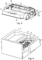
- Figure 1 is a sectional view of an image formation main assembly 1 (main assembly), and a process cartridge 2 (cartridge) of an image forming apparatus in an embodiment of the present invention.
- Figure 2 is an enlarged cross-sectional view of the cartridge 2. Referring to Figures 1 - 2 , a general arrangement, and an image formation process of the image forming apparatus in the present embodiment will be described.
- This image forming apparatus is a laser beam printer which utilizes electrophotography, wherein a cartridge 2 is detachably mountable to the main assembly 1.
- a cartridge 2 is detachably mountable to the main assembly 1.
- an exposure device (laser scanner unit) 3 is disposed on the upper portion of the cartridge 2.
- the lower portion of the cartridge 2 is provided with a sheet tray 4 which contains recording material (sheet material) P which is the object on which an image is formed.
- the main assembly 1 is provided with a pick-up roller 5a, a feeding roller 5b, a feeding roller pair 5c, a transfer guide 6, a transfer charging roller 7, a feeding guide 8, a fixing device 9, a discharging roller pair 10, a discharging tray 11, and so on along a feeding direction of the sheet material P.
- an electrophotographic photosensitive member drum (drum) 20 is rotated at a predetermined peripheral speed (process speed) in a direction of the arrow R1.
- the a charging roller (charging means, process means) 12 which is supplied with a bias voltage contacts to an outer surface of the drum 20, and the outer surface of by drum 20 is uniformly charged by the charging roller 12.
- a laser beam L modulated correspondingly to a serial electrical digital pixel signal of the image information is outputted from the exposure device 3.
- the laser beam L enters the cartridge 2 through an exposure window 53 of an upper surface of the cartridge 2 to scanningly expose the outer surface of the drum 20 by this, an electrostatic latent image corresponding to the image information is formed on the outer surface of the drum 20.
- the electrostatic latent image is visualized by a developer T (toner) of a developing device unit 40 into a Toner image.
- the charging roller 12 is contacted to the drum 20, and charges the drum 20 electrically.
- the charging roller 12 is rotated by the drum 20.
- the developing device unit 40 supplies the toner into the developing zone of the drum 20 to develop the latent image formed on the drum 20.
- the developing device unit 40 feeds the toner T in a toner chamber 45 to a toner feeding chamber 44 by the rotation of a stirring member 43.
- the developing roller (developing means, process means) 41 which is a developer carrying member containing a magnet roller (stationary magnet) 41a is rotated, and the toner layer triboelectrically charged by the developing blade 42 is formed on the surface of the developing roller 41.
- the toner is transferred onto the drum 20 in accordance with the latent image, so that the electrostatic latent image is visualized into a toner image.
- the developing blade 42 applies the triboelectrical charge while regulating the toner amount on the peripheral surface of the developing roller 41.
- the paper is fed to the sheet material P accommodated in the lower portion of the main assembly 1 from the sheet tray 4 by the pick-up roller 5a, the feeding roller 5b, and feeding roller pair 5c.
- the sheet material P is timed and fed to a transfer position between the drum 20, and a transfer charging roller 7 via the transfer guide 6. In the transfer position, the toner image is transferred onto the sheet material P sequentially from the drum 20.
- the sheet P onto which the toner image has been transferred is separated from the drum 20, and fed to the fixing device 9 along the feeding guide 8.
- the sheet material P is passed through a nip formed between a fixing roller 9a, and a pressing roller 9b which constitute the fixing device 9.
- the pressing and the heat-fixing process are carried out in the nip so that toner image is fixed on the sheet material P.
- the sheet material P having been subjected to the image fixing process for the toner image is fed to discharging roller pair 10, and is discharged to the discharging tray 11.
- the drum 20 is used for the next image formation which starts with the electrical charging operation.
- the waste toner removed from the drum 20 is stored in the waste toner chamber 52a in the photosensitive member unit 50.
- the charging roller 12, the developing roller 41, the cleaning blade 52, and so on are the process means actable on the drum 20, respectively.
- Figure 3 is a perspective view illustrating structures of a frame of the cartridge 2.
- the drum 20, the charging roller 12, and the cleaning blade 52 is mounted to the drum frame 51, and constitutes an integral photosensitive member unit 50.
- the developing device unit 40 is constituted by the toner chamber 45 which contains the toner, the toner accommodating chamber 40a which forms the toner feeding chamber 44, and the cover 40b.
- the toner accommodating chamber 40a and the cover 40b is connected relative to each other by the means such as the welding.
- the cartridge 2 is constituted by connecting the photosensitive member unit 50 and the developing device unit 40 rotatably relative to each other by a connection member 54 of a round pin.
- the free end of an arm portion 55a formed on a side cover 55 provided at each end with respect to the longitudinal direction of the developing device unit 40 (axial direction of the developing roller 41) is provided with a round rotation hole extending in parallel with the developing roller 41 55b.
- the drum frame 51 has an engaging hole 51a for receiving the connection member 54 co-axially with the rotation hole 55b when the arm portion 55a is inserted in the predetermined position of the drum frame 51.
- the photosensitive member unit 50 and the developing device unit 40 are connected with each other rotatably about the connection member 54 by inserting the connection member 54 through both the rotation hole 55b and the engaging hole 51a.
- a compression coil spring 46 mounted to the base portion of the arm portion 55a abuts to the drum frame 51 to urge the developing device unit 40 downwardly.
- the spacing members are mounted at the opposite ends of the developing roller 41, so that the developing roller 41, is held with predetermined intervals from the drum 20.
- Figure 4 is a perspective view of an inside of the main assembly with the door 140 open.
- the cartridge 2 is not mounted.
- a guiding rail 130 for the cartridge mounting and demounting is provided in the main assembly 1, and the cartridge 2 is mounted into the inside of the main assembly 1 along a guiding rail 130.
- a drive shaft 100 of the main assembly side and a coupling member 156 which is a rotational force transmitting portion of the cartridge 2 connect with each other in interrelation with the mounting operation of the cartridge 2.
- the drum 20 receives the rotational force from the main assembly 1 to rotate.
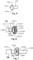
- Figure 5 is a perspective view of the drive shaft 100 of the main assembly side.
- the drive shaft 100 is coupled with the drive transmitting means, such as an unshown gear train and the unshown motor provided in the main assembly 1.
- the free end portion 100a of the drive shaft 100 has a substantial semispherical shape, and is provided with rotational force transmitting pins as the rotational force applying portion 100b.
- the coupling member 156 has the function of receiving a rotational force for rotating the drum 20 from the main assembly 1.
- this coupling member 156 has a rotational force receiving member 150 which has a rotational force receiving portion 150e (150e1 - 150e4) for receiving the rotational force at the free end portion thereof.
- spherical portion 160 mounted by penetrating the pin 155 through a rear end portion of the rotational force receiving member 150.
- Figure 6 is a perspective view of the rotational force receiving member 150.
- the material of the rotational force receiving member 150 is resin material of the polyacetal, the polycarbonate, PPS, or the like.
- glass fibers, carbon fibers, and/or the like may be mixed in the resin material in response to the required torque load.
- the rigidity of the rotational force receiving member 150 can be enhanced.
- the rigidity may further be enhanced by inserting a metal member material in the resin material, and the whole rotational force receiving member 150 may be made of metal or the like.
- the free end of the rotational force receiving member 150 is provided with a plurality of drive receiving projections 150d (150d1 - 150d4).
- the drive receiving projection 150d (150d1 - 150d4) is provided with rotational force receiving portion 150e (150e1 - 150e4) inclined relative to the axis L150 of the rotational force receiving member 150.
- drive receiving projection 150d1 - 150d4 is provided with a funnel-like funnel 150f as a recessed portion.
- Figure 7 is an illustration showing the state that the rotational force receiving member 150 of the coupling member 156 and the drive shaft 100 connects with each other.
- Figure 8 is a sectional view illustrating the state that the rotational force receiving member 150 and the drive shaft 100 connect with each other.
- the rotational force transmitting pin 100b of the drive shaft 100 is in engagement with the rotational force receiving portion 150e (150e1 - 150e4).
- the free end portion 100a of the drive shaft 100 is in contact with the recessed portion 150f of the rotational force receiving member 150.
- the rotational force is transmitted from the rotational force transmitting pin 100b to the rotational force receiving portion 150e by the drive shaft 100 rotating.
- the rotational force receiving portion 150e inclining relative to the axis L150 of the rotational force receiving member 150, the rotational force receiving member 150 and the drive shaft 100 are attracted relative to each other and the free end portion 100a and the recessed portion 150f contact them to each other assuredly, so that the stabilized rotational force transmission is accomplished.
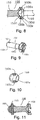
- Figure 9 is a perspective view illustrating the rotational force receiving member 150
- Figure 10 is a perspective view illustrating the spherical portion 160.
- Figure 11 is a sectional view of the coupling member 156
- Figure 12 is a perspective view of the coupling member 156.
- the end on the side opposite from the rotational force receiving portion 150e of the rotational force receiving member 150 150s is provided with a through-hole 150r.
- the spherical portion 160 connected with the rotational force receiving member 150 has the substantial spherical shape and is provided with the rotational force receiving member 150 and the hole for receiving the pin 155 as will be described hereinafter.
- a one-end-closed hole 160a receives the end 150s of the rotational force receiving member 150.
- the through-hole 160b receives the pin 155 which will be described hereinafter with the hole 160a.
- the rotational force receiving member 150 is inserted into the spherical portion 160, and the pin 155 is inserted in the state that the through-hole 150r and the through-hole 160b are aligned with each other.
- the rotational force receiving member 150 and the one-end-closed-hole 160a are engaged with each other with the loose-fit.
- the pin 155 and the through-hole 150r are engaged with each other with the loose-fit.
- the pin 155 and the through-hole 160b are engaged with each other with the press-fit.
- the pin 155 and the spherical portion 160 are connected with each other integrally.
- a part provided by the connection between the rotational force receiving member 150 and the spherical portion 160 is the coupling member 156.
- the rotational force receiving member 150 rotates about the axis L150, and the through-hole 150r is engaged with the pin 155.
- the rotational force from the main assembly 1 is converted to the force for rotating the pin 155 about the rotation shaft L150 through the rotational force receiving member 150.
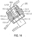
- Figure 13 is an illustration illustrating the drum flange 151
- Figure 14 is a sectional view taken along line S2-S2 in Figure 13 .
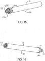
- FIG 15 is a perspective view of the electrophotographic photosensitive drum unit (drum unit) 21, as seen from the driving side (rotational force receiving member 150).
- Figure 16 is a perspective view of the drum unit 21, as seen from the non-driving side (longitudinally opposite from the rotational force receiving member 150).
- Figure 13 illustrates the flange 151, as seen from the drive shaft 100 side.
- An opening 151g (151g1 - 151g4) shown in Figure 13 is a groove which extends in the direction of a rotation shaft of the flange 151.
- the clockwisely upstream side of openings 151g1 - 151g4 is provided with the rotational force transmitting surface (rotational force receiving portion) 151h (151h1 - 151h4).
- a recessed space 151f is formed adjacent to the center axis L151 of the flange 151.
- the recessed space 151f provides a space surrounded by the cylindrical surface 151j (151j1 - 151j4), a retaining portion 151i (151i1 - 151i4) which is a regulating portion, and the opening 151k (151k1 - 151k4).
- the cylindrical surface 151j (151j1 - 151j4) is a substantially cylindrical surface which is co-axial with the axis L151 and which is adjacent to the opening 151g, and has diameter D151a.
- the retaining portion 151i (151i1 - 151i4) is a substantially semispherical surface which continues smoothly with the cylindrical surface 151j, and has the radius of SR151.
- the opening 151k (151k1 - 151k4) is positioned at the drive shaft side of the retaining portion 151i, and has diameter of D151b.
- the opening 151k is a first surface of the regulating portion which continues from the retaining portion 151i (regulating portion) and which is extended in the direction away from the coupling member 156 toward the free end of the rotational force receiving member 150 with respect to the longitudinal direction of the drum 20.
- the spherical portion 160 can be inserted with the gap G ( Figure 17 ) into the recessed space 151f, the movement toward the opening 151k of the axis L151 is prohibited.
- the spherical portion 160 does not separate from the flange 151 (process cartridge 2) under the normal service condition by this prohibition.
- the flange 151 is mounted to the end of the drum 20, and the coupling member 156 is mounted to this flange 151.
- the flange 151 is provided with the regulating portion extended along the inside peripheral surface of the flange 151 (retaining portion 151i).
- This regulating portion (retaining portion 151i) has the gap G relative to the spherical portion 160, and has a nearer configuration to the configuration of the surface of the spherical portion 160 of the rotational force receiving member 150 than a flat plane which is perpendicular to the longitudinal direction of the drum 20 and which passes through the center of the spherical portion 160.
- the flange 151 which has the mounted coupling member 156 is fixed to the end side of the drum 20 so that the drive receiving projection 150d is exposed,
- drum flange 152 of the non-driving side is fixed to the other end side of the drum 20.
- the fixing method may be the crimping, the bonding, the welding, and so on.
- the rotational force from the motor (unshown) of the main assembly 1 rotates the drive shaft 100 through the drive transmitting means, such as the gear of the main assembly 1 (unshown).
- the rotational force is transmitted to the cartridge 2 through the rotational force receiving member 150 of the coupling member 156.
- the rotational force is transmitted from the rotational force receiving member 150 to the flange 151 through the pin 155 to apply the rotational force to the drum 20 integrally fixed to the flange 151.
- the outside periphery of the flange 151 is provided with a helical gear molded integrally with the flange 151 151c.
- This gear 151c transmits the rotational force received from the drive shaft 100 by the rotational force receiving member 150 to the developing roller 41 ( Figure 2 ).
- the outside portion opposed to the retaining portion which is the regulating portion 151i of the flange 151 is provided with the helical gear 151c, and the gear transmits the rotational force received from the main assembly 1 by the coupling member 156 to the developing roller 41.
- Figure 17 is a detailed view of the opening 151k portion (surrounded portion) in Figure 14 .
- the flange 151 Since the flange 151 has the gear 151c, usually, it is made of resin material of a high slidability, such as polyacetal.
- the spherical portion 160 swings in the recessed space 151f similarly, it is made of a resin members, such as polyacetal, similarly.
- the spherical portion 160 and the flange 151 are made of resin material.
- the outside dimension D160 of the spherical portion 160 is larger than the diameter D151b of the opening 151k, and therefore, usually, at the time of the usage, it does not separate from the spherical portion 160 (coupling member 156) from the flange 151 (process cartridge 2).
- the opening 151k is continuing with the retaining portion 151i, and inclines away from the coupling member 156 (spherical portion 160).
- the difference between the outside dimension of the spherical portion 160 D160 and the diameter of the opening 151k D151b is approx. 0.4mm.
- the flange 151 and the spherical portion 160 are made of resin material, they relatively easily deform in accordance with the external force.
- the outside dimension D160 of the spherical portion 160 reduces, and, the retaining portion 151i, the opening 151k, and taper surface 151n of the flange 151 deforms outwardly in the radial direction from the axis L151 of the flange 151 (direction indicated by the arrow in Figure 17 ).
- the taper surface 151n of the flange 151 extends to the opening 151k, and it inclines away from the coupling member 156 toward the free end side of the coupling member 156 which is in the driven portion side with respect to the axial direction L151.
- This taper surface 151n is the portion of the second surface of the regulating portion 151S.
- the taper surface 151n is inclined from the opening which is the first surface of the retaining portion 151i which is the regulating portion 151S 151k, and is extended away from the coupling member 156 toward the free end of the rotational force receiving member 150 with respect to the longitudinal direction of the drum.
- the spherical portion 160 the retaining portion which is the regulating portion 151S which projects radially inwardly of the flange 151 sets, the opening 151k, and taper surface 151n bend, and at the time of the diameter of the opening 151k D151b and the outside dimension of the spherical portion 160 D160 can become the same.
- the flexibility of the flange regulating portion (retaining portion 151i, opening 151k, taper surface 151n) of the drum flange 151 depends on the recess 151q1-8 which is in the positions outside in the radial direction of the drum flange 151 as seen from the regulating portion part 151S Figure 13 .
- the dimensional relation in this embodiment is selected such that in the normal use, the retention function is effective.
- the recesses 151q (151q1 - 151q8) are provided in the symmetric positions with respect to the axis 151 L of the flange 151.
- the recess 151q1 and the recess 151q5, the recess 151q2 and the recess 151q6, the recess 151q3 and the recess 151q7, and the recess 151q4 and the recess 151q8 are provided at the symmetric positions with respect to the axis 151L, respectively.
- the axis 151L is aligned with the axis 20L of the drum 20, and with the axis 20AL of the drum cylinder 20A ( Figure 13 , Figure 17 ).
- Designated by reference character S is the photosensitive layer.
- a first method is the same as the assembling method of the drum unit 21 described above substantially.
- the rotational force receiving member 150 is inserted into the flange 151, and the spherical portion 160 is covered.
- the rotational force receiving member 150, the spherical member 160, and the pin 155 are integrally connected by the pin 155, and the coupling member 15 is assembled to the flange 151.
- non-driving side drum flange 152 is fixed to the other end portion of the drum 20 ( Figure 16 ).
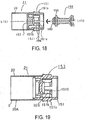
- Figure 18 and Figure 19 are sectional views illustrating the assembling method of the drum unit 21 according to another embodiment.
- Figures 18 and 19 are a sectional views taken along a line S1-S1 in Figure 13 .
- Figure 20 is a sectional view illustrating a drum unit 21 of the other embodiment.
- the coupling member 156 is assembled in the flange 151, but in the present embodiment, the coupling member 156 is assembled independently.
- the retaining member 157 is fixed to the flange 151, and then the drum 20 and the flange 151 are connected with each other. Furthermore, non-driving side drum flange 152 is fixed to the other end portion of the drum 20 ( Figure 16 , Figure 20 ).
- the coupling member 156 is pushed in the direction of the arrow in Figure 31, and the spherical portion 160 is contacted to the tapered surface 151n, and when it is further pushed in, the spherical portion 160, and the neighborhood of the tapered surface 151n of the flange 151 which is the regulating portion deforms (arrow in Figure 17 ).
- the spherical portion 160 (coupling member 156) can be accommodated in the recessed space 151f by this deformation.
- the easiness of the deformations of the regulating portion 151S (retaining portion 151i, the opening 151k, tapered surface 151n) of the flange 151 depend on the recess 151q ( Figure 13 , Figure 20 ) which is in the outside of the regulating portions 151S with respect to the radial direction of the drum flange 151, and the easiness is increased with the size of the recess 151q.
- the dimensional relations are such that at the time of the usage, it has the retention function normally, and is easily pushed in. It is not inevitable that the regulating portion 151S has the retaining portion 151i, the opening 151k, and the tapered surface 151n.
- the regulating portion 151S may have the retaining portion 151i at least.
- the spherical portion 160 contacts to the tapered surface 151n, and the center position of the spherical portion 160 is regulated on the axis of the flange 151.
- the contacted state of the spherical portion 160 relative to the tapered surface 151n is uniform.
- the regulating portion 151S deforms uniformly, and therefore, the spherical portion 160 can be smoothly mounted to the flange 151.
- the damage can be prevented when they contact.
- the coupling member 156 is made of the metal, and therefore, the strength is high.
- the center position of the spherical portion 160 is set on the axis 151L. Accordingly, the coupling member 156 can be smoothly mounted to the flange 151.
- the spherical portion 160 at least the portion contacted to the regulating portion 151S has the spherical configuration when mounting the coupling member 156 smoothly to the flange 151.
- the pin 155 can be inserted into the spherical portion 160 and the rotating force receiving portion 150 without inserting the rotational force receiving member 150 into the flange 151, and therefore, the insertion of the pin 155 is easy.
- it is not necessary to mount the parts from the retaining member 157 side, and therefore, it can manufacture as a single part by molding the flange 151, and the retaining member 157 integrally (integral-type flange 153), as shown in Figure 19 . By this, the simplification of the manufacturing step, and the cost reduction of the product are accomplished.
- the cleaning blade 52, the charging roller 12, and the drum unit 21 are mounted in the order named order.
- connection member 54 Figure 3
- the photosensitive member unit 50, and the developing device unit 40 are connected rotatably with each other.
- the process cartridge which is easy in assembling is provided.
- the structure of the drum unit 21 is as follows.
- the coupling member 156 is mountable to the drum unit 21. And, the coupling member 156 has the rotational force receiving member 150 which has the rotational force receiving portion 151e for receiving the rotational force at the free end portion, and the spherical portion 160 mounted by the penetration of the pin 155 at the rear end portion of the rotational force receiving member 150 in order to rotate the drum 20 from the main assembly 1 of the electrophotographic image forming apparatus.
- the drum unit 21 has the cylinder 20A which is provided with the photosensitive layer S at the peripheral surface, and the drum flange 151 provided at the end of the cylinder 20A.
- the drum flange 151 has the resin material regulating portion 151S which inwardly projects with respect to the radial direction of the drum flange 151 in the inside of the drum flange 151.
- the regulating portion 151S prevents the spherical portion 160 from moving in the longitudinal direction of the drum unit 21, when the coupling member 156 is mounted.
- the regulating portions 151S are provided with the intervals along the circumferential direction in the inside of the flange 151.
- the drum flange 151 has the recess 151q (151q1 to 151q8) provided in the flange 151 radially outside of the regulating portion 151S, wherein the recess 151q facilitates or permits the regulating portion 151S to outwardly deform with respect to the radial direction of the flange 151.
- the flange 151 has a plurality of rotational force transmitting surface (rotational force transmitted portion) 151h (151h1-151h4) which are provided between the regulating portions 151S in order to receive the rotational force from the pin 155.
- the resin material regulating portions 151S are provided at the same positions as the gear portion 151C with respect to the longitudinal direction of the cylinder 20A in the resin flange 151, and they are disposed with the intervals along the circumferential direction of the cylinder 20A. And, in the regulating portion 151S, the free end portion with respect to the longitudinal direction of the cylinder 20A inwardly projects with respect to the radial direction of the flange 151.
- the recess 151q (151q1 to 151q8) is provided between the regulating portion 151S, and the inner surface 151t ( Figure 13 , Figure 20 ) of the flange 151 with respect to the radial direction. And, the recess 151q facilitates or permits the regulating portion 151S to outwardly deform with respect to the radial direction.
- the regulating portion 151S outwardly deforms easily with respect to the radial direction by the provision of the recess 151q. In addition, thereafter, the regulating portion 151S which deformed is restored.
- 151r ( Figure 13 ) is the connecting portion for connecting the regulating portion 151S, and the inner surface 151t ( Figure 13 , Figure 20 ) of the flange 151 with each other.
- the recess 151q is provided between the connecting portions 151r.
- the connecting portion 151r, and the recess 151q are provided by turns along the circumferential direction of the flange 151. Therefore, the regulating portion 151S deforms easily.
- the coupling member 156 is mounted to the flange 151.
- the coupling member 156 receives the rotational force to be transmitted from the main assembly 1 to the flange 1.
- the coupling member 156 has the rotational force receiving member 150 which has the rotational force receiving portion 150e (150e1 to 150e4) for receiving the rotational force at the free end portion, and the spherical portion 160 mounted by the penetration of the pin 155 at the rear end portion of the rotational force receiving member 150.
- the pin 155 is movable in the circumferential direction, and the longitudinal direction of the cylinder between the regulating portion 151S, and the regulating portion 151S provided along the circumferential direction of the flange 155.
- the coupling member 156 is revolvable relative to the flange 151 in the state in which the spherical portion 160 is movable in the circumferential direction, and is regulated in the movement in the longitudinal direction by the regulating portion 151S.
- the coupling member 156 is mounted revolvably to the flange 151 in the state that the spherical portion 160 is movable within the limits that the pin 155 is regulated in the movement by the regulating portion 151S in the circumferential direction, and it is regulated in the movement by the regulating portion 151S in the longitudinal direction.
- the mounting of the coupling member 156 is easy.
- an easy mounting method for the coupling member can be provided.
- the electrophotographic photosensitive drum unit to which the coupling member can be easily mounted can be provided.
- the present invention can provide an easy mounting method for a coupling member.
- the present invention can further provide an electrophotographic photosensitive drum unit, wherein mounting of the coupling is easy.
Description
- The present invention relates to an electrophotographic photosensitive drum unit used for a process cartridge dismountably mounted to a main assembly of an electrophotographic image forming apparatus and a coupling member mounting method. Here, in the present invention, the process cartridge contains as a unit at least one of an electrophotographic photosensitive member drum, developing means as process means actable on the drum, cleaning means, and charging means. And, it is detachably mountable to the electrophotographic image forming apparatus main assembly.
- In addition, the electrophotographic image forming apparatus forms an image on a recording material through an electrophotographic type process. As examples of the electrophotographic image forming apparatus, there are an electrophotographic copying machine, an electrophotographic printer (LED printer, a laser beam printer), a facsimile device, a word processor, and so on.
- In addition, the main assembly of the electrophotographic image forming apparatus is a portion of the electrophotographic image forming apparatus except the process cartridge.
- In a known electrophotographic image forming apparatus in which the electrophotographic image forming process is used the electrophotographic photosensitive member drum, and the process means actable on the electrophotographic photosensitive member drum are integrated into a cartridge as a unit. And, this cartridge is detachably mountable to the main assembly of the electrophotographic image forming apparatus process cartridge type.
- According to this process cartridge type the maintenance of the image forming apparatus can be carried out by the user himself or herself without relying on the service person, and therefore, the operativity of the maintenance is remarkably improved.
- In addition, in the electrophotographic image forming apparatus, an image is formed on a recording material using a developer. The developer contained in the developer accommodating portion is consumed as the process cartridge having the developing means repeats the image formation.
- An easy assembling method of the process cartridge has been desired. The present invention further develops the above described prior art.
- Electrophotographic photosensitive drum units and methods for mounting a coupling member are known from
US 2008/0152388 A1 andUS 2007/0237545 A1 . Furthermore,WO 2009/154311 A1 shows an electrophotographic photosensitive drum unit and a method for mounting a coupling member. - Accordingly, it is an object of the present invention to provide an electrophotographic photosensitive drum unit and a coupling member mounting method, wherein mounting of the coupling member is easy.
- This object is achieved by an electrophotographic photosensitive drum unit having the features of
claim 1 or a method for mounting a coupling member having the features ofclaim 6. - Advantageous further developments are set out in the dependent claims.
- The object as well as features and advantages of the present invention will become more apparent upon consideration of the following description of the preferred embodiments of the present invention, taken in conjunction with the accompanying drawings.
-
-
Figure 1 is a sectional view of a main assembly, and a process cartridge of an image forming apparatus in an embodiment. -
Figure 2 is an enlarged cross-sectional view of the process cartridge. -
Figure 3 is a perspective view illustrating a frame structure of the process cartridge. -
Figure 4 is a perspective view of the main assembly in the state that an openable and closable door is opened. -
Figure 5 is a perspective view of a drive shaft of the main assembly. -
Figure 6 is a perspective view of a free end portion of a coupling member. -
Figure 7 is an illustration showing the state that the coupling member and the drive shaft are connected with each other. -
Figure 8 is a sectional view illustrating the state that the coupling member and the drive shaft are connected with each other. -
Figure 9 is a perspective view of a rotational force receiving member which is a component part of the coupling member. -
Figure 10 is a perspective view of a spherical portion which is a component part of the coupling member. -
Figure 11 is a sectional view of the coupling member. -
Figure 12 is a perspective view of the coupling member. -
Figure 13 is an illustration of a drum flange. -
Figure 14 is a sectional view taken along a line S2-S2 inFigure 13 . -
Figure 15 is a perspective view of the drum unit, as seen from a driving side. -
Figure 16 is a perspective view of the drum unit, as seen from a non-driving side. -
Figure 17 is a partial enlarged view of the opening portion inFigure 14 . -
Figure 18 is a sectional view illustrating a method of assembling the drum unit. -
Figure 19 is a sectional view illustrating a method of assembling of the drum unit. -
Figure 20 is a sectional view illustrating a method for assembling the drum unit. - Referring to the accompanying drawings, the preferred embodiments of the present invention will be described. The function, material, configuration, positional relations and the like of the elements described hereinbelow is not limiting to the present invention unless otherwise stated. As for the material, configuration and the like of the elements described once apply to the subsequent descriptions unless otherwise stated.
-
Figure 1 is a sectional view of an image formation main assembly 1 (main assembly), and a process cartridge 2 (cartridge) of an image forming apparatus in an embodiment of the present invention.Figure 2 is an enlarged cross-sectional view of thecartridge 2. Referring toFigures 1 - 2 , a general arrangement, and an image formation process of the image forming apparatus in the present embodiment will be described. - This image forming apparatus is a laser beam printer which utilizes electrophotography, wherein a
cartridge 2 is detachably mountable to themain assembly 1. When thecartridge 2 is set to themain assembly 1, an exposure device (laser scanner unit) 3 is disposed on the upper portion of thecartridge 2. The lower portion of thecartridge 2 is provided with asheet tray 4 which contains recording material (sheet material) P which is the object on which an image is formed. Themain assembly 1 is provided with a pick-up roller 5a, a feeding roller 5b, a feeding roller pair 5c, atransfer guide 6, a transfer charging roller 7, a feeding guide 8, afixing device 9, adischarging roller pair 10, adischarging tray 11, and so on along a feeding direction of the sheet material P. - The outline of the image formation process will be described. In response to a print start signal, an electrophotographic photosensitive member drum (drum) 20 is rotated at a predetermined peripheral speed (process speed) in a direction of the arrow R1. The a charging roller (charging means, process means) 12 which is supplied with a bias voltage contacts to an outer surface of the
drum 20, and the outer surface of bydrum 20 is uniformly charged by thecharging roller 12. - A laser beam L modulated correspondingly to a serial electrical digital pixel signal of the image information is outputted from the
exposure device 3. The laser beam L enters thecartridge 2 through an exposure window 53 of an upper surface of thecartridge 2 to scanningly expose the outer surface of thedrum 20 by this, an electrostatic latent image corresponding to the image information is formed on the outer surface of thedrum 20. The electrostatic latent image is visualized by a developer T (toner) of a developingdevice unit 40 into a Toner image. - The
charging roller 12 is contacted to thedrum 20, and charges thedrum 20 electrically. Thecharging roller 12 is rotated by thedrum 20. The developingdevice unit 40 supplies the toner into the developing zone of thedrum 20 to develop the latent image formed on thedrum 20. - The developing
device unit 40 feeds the toner T in atoner chamber 45 to atoner feeding chamber 44 by the rotation of a stirring member 43. The developing roller (developing means, process means) 41 which is a developer carrying member containing a magnet roller (stationary magnet) 41a is rotated, and the toner layer triboelectrically charged by the developingblade 42 is formed on the surface of the developingroller 41. The toner is transferred onto thedrum 20 in accordance with the latent image, so that the electrostatic latent image is visualized into a toner image. The developingblade 42 applies the triboelectrical charge while regulating the toner amount on the peripheral surface of the developingroller 41. - On the other hand, and in accordance with the output timing of the laser beam L, the paper is fed to the sheet material P accommodated in the lower portion of the
main assembly 1 from thesheet tray 4 by the pick-up roller 5a, the feeding roller 5b, and feeding roller pair 5c. The sheet material P is timed and fed to a transfer position between thedrum 20, and a transfer charging roller 7 via thetransfer guide 6. In the transfer position, the toner image is transferred onto the sheet material P sequentially from thedrum 20. - The sheet P onto which the toner image has been transferred is separated from the
drum 20, and fed to thefixing device 9 along the feeding guide 8. The sheet material P is passed through a nip formed between a fixing roller 9a, and a pressing roller 9b which constitute the fixingdevice 9. The pressing and the heat-fixing process are carried out in the nip so that toner image is fixed on the sheet material P. The sheet material P having been subjected to the image fixing process for the toner image is fed to dischargingroller pair 10, and is discharged to the dischargingtray 11. - On the other hand, and the residual toner remaining on the outer surface of the
drum 20 is removed by a cleaning blade (cleaning means, process means) 52 after the transferring 20, and the drum is used for the next image formation which starts with the electrical charging operation. The waste toner removed from thedrum 20 is stored in thewaste toner chamber 52a in thephotosensitive member unit 50. - The charging
roller 12, the developingroller 41, thecleaning blade 52, and so on are the process means actable on thedrum 20, respectively. -
Figure 3 is a perspective view illustrating structures of a frame of thecartridge 2. - Referring to
Figure 2 andFigure 3 , the frame structure of thecartridge 2 will be described. - As shown in
Figure 2 , thedrum 20, the chargingroller 12, and thecleaning blade 52 is mounted to thedrum frame 51, and constitutes an integralphotosensitive member unit 50. - On the other hand, the developing
device unit 40 is constituted by thetoner chamber 45 which contains the toner, the toner accommodating chamber 40a which forms thetoner feeding chamber 44, and thecover 40b. - The toner accommodating chamber 40a and the
cover 40b is connected relative to each other by the means such as the welding. - As shown in
Figure 3 , thecartridge 2 is constituted by connecting thephotosensitive member unit 50 and the developingdevice unit 40 rotatably relative to each other by aconnection member 54 of a round pin. - As shown in
Figure 3 , the free end of an arm portion 55a formed on aside cover 55 provided at each end with respect to the longitudinal direction of the developing device unit 40 (axial direction of the developing roller 41) is provided with a round rotation hole extending in parallel with the developingroller 41 55b. - The
drum frame 51 has an engaging hole 51a for receiving theconnection member 54 co-axially with therotation hole 55b when the arm portion 55a is inserted in the predetermined position of thedrum frame 51. - The
photosensitive member unit 50 and the developingdevice unit 40 are connected with each other rotatably about theconnection member 54 by inserting theconnection member 54 through both therotation hole 55b and the engaging hole 51a. - At this time, a
compression coil spring 46 mounted to the base portion of the arm portion 55a abuts to thedrum frame 51 to urge the developingdevice unit 40 downwardly. - By this, the developing roller 41 (
Figure 2 ) is assuredly pressed toward thedrum 20. - The spacing members (unshown) are mounted at the opposite ends of the developing
roller 41, so that the developingroller 41, is held with predetermined intervals from thedrum 20. -
Figure 4 is a perspective view of an inside of the main assembly with thedoor 140 open. - The
cartridge 2 is not mounted. - Referring to
Figure 4 , the rotational force transmission method to thecartridge 2 will be described. - As shown in
Figure 4 , a guidingrail 130 for the cartridge mounting and demounting is provided in themain assembly 1, and thecartridge 2 is mounted into the inside of themain assembly 1 along a guidingrail 130. - In this case, a
drive shaft 100 of the main assembly side and a coupling member 156 (Figure 3 ) which is a rotational force transmitting portion of thecartridge 2 connect with each other in interrelation with the mounting operation of thecartridge 2. - By this, the
drum 20 receives the rotational force from themain assembly 1 to rotate. -
Figure 5 is a perspective view of thedrive shaft 100 of the main assembly side. - The
drive shaft 100 is coupled with the drive transmitting means, such as an unshown gear train and the unshown motor provided in themain assembly 1. - The
free end portion 100a of thedrive shaft 100 has a substantial semispherical shape, and is provided with rotational force transmitting pins as the rotationalforce applying portion 100b. - In the state where the
cartridge 2 is dismountably mounted to themain assembly 1, thecoupling member 156 has the function of receiving a rotational force for rotating thedrum 20 from themain assembly 1. - As shown in
Figure 11 andFigure 12 , thiscoupling member 156 has a rotationalforce receiving member 150 which has a rotationalforce receiving portion 150e (150e1 - 150e4) for receiving the rotational force at the free end portion thereof. - In addition, it has a spherical portion (spherical member) 160 mounted by penetrating the
pin 155 through a rear end portion of the rotationalforce receiving member 150. -
Figure 6 is a perspective view of the rotationalforce receiving member 150. - The material of the rotational
force receiving member 150 is resin material of the polyacetal, the polycarbonate, PPS, or the like. - However, in order to enhance the rigidity of the rotational
force receiving member 150, glass fibers, carbon fibers, and/or the like may be mixed in the resin material in response to the required torque load. - In the case of mixing such a material, the rigidity of the rotational
force receiving member 150 can be enhanced. - The rigidity may further be enhanced by inserting a metal member material in the resin material, and the whole rotational
force receiving member 150 may be made of metal or the like. - The free end of the rotational
force receiving member 150 is provided with a plurality ofdrive receiving projections 150d (150d1 - 150d4). - In addition, the
drive receiving projection 150d (150d1 - 150d4) is provided with rotationalforce receiving portion 150e (150e1 - 150e4) inclined relative to the axis L150 of the rotationalforce receiving member 150. - In addition, the inside of drive receiving projection 150d1 - 150d4 is provided with a funnel-like funnel 150f as a recessed portion.
-
Figure 7 is an illustration showing the state that the rotationalforce receiving member 150 of thecoupling member 156 and thedrive shaft 100 connects with each other. -
Figure 8 is a sectional view illustrating the state that the rotationalforce receiving member 150 and thedrive shaft 100 connect with each other. - Referring to
Figure 7 andFigure 8 , the connection state between the drive shaft, 100 and thecoupling member 156 will be described. - The rotational
force transmitting pin 100b of thedrive shaft 100 is in engagement with the rotationalforce receiving portion 150e (150e1 - 150e4). - Although it is not visible in
Figure 7 , the rotationalforce transmitting pin 100b on the back side is also in engagement with the rotationalforce receiving portion 150e. - In addition, the
free end portion 100a of thedrive shaft 100 is in contact with the recessed portion 150f of the rotationalforce receiving member 150. - The rotational force is transmitted from the rotational
force transmitting pin 100b to the rotationalforce receiving portion 150e by thedrive shaft 100 rotating. - In addition, by the rotational
force receiving portion 150e inclining relative to the axis L150 of the rotationalforce receiving member 150, the rotationalforce receiving member 150 and thedrive shaft 100 are attracted relative to each other and thefree end portion 100a and the recessed portion 150f contact them to each other assuredly, so that the stabilized rotational force transmission is accomplished. -
Figure 9 is a perspective view illustrating the rotationalforce receiving member 150, andFigure 10 is a perspective view illustrating thespherical portion 160. -
Figure 11 is a sectional view of thecoupling member 156, andFigure 12 is a perspective view of thecoupling member 156. - As shown in
Figure 9 , the end on the side opposite from the rotationalforce receiving portion 150e of the rotationalforce receiving member 150 150s is provided with a through-hole 150r. - As shown in
Figure 10 , thespherical portion 160 connected with the rotationalforce receiving member 150 has the substantial spherical shape and is provided with the rotationalforce receiving member 150 and the hole for receiving thepin 155 as will be described hereinafter. - A one-end-closed
hole 160a receives theend 150s of the rotationalforce receiving member 150. - The through-
hole 160b receives thepin 155 which will be described hereinafter with thehole 160a. - As shown in
Figure 11 andFigure 12 , the rotationalforce receiving member 150 is inserted into thespherical portion 160, and thepin 155 is inserted in the state that the through-hole 150r and the through-hole 160b are aligned with each other. - In this embodiment, the rotational
force receiving member 150 and the one-end-closed-hole 160a are engaged with each other with the loose-fit. - The
pin 155 and the through-hole 150r are engaged with each other with the loose-fit. - The
pin 155 and the through-hole 160b are engaged with each other with the press-fit. - Accordingly, the
pin 155 and thespherical portion 160 are connected with each other integrally. - A part provided by the connection between the rotational
force receiving member 150 and thespherical portion 160 is thecoupling member 156. - When the rotational force is received from the
drive shaft 100, the rotationalforce receiving member 150 rotates about the axis L150, and the through-hole 150r is engaged with thepin 155. - More particularly, the rotational force from the
main assembly 1 is converted to the force for rotating thepin 155 about the rotation shaft L150 through the rotationalforce receiving member 150. -
Figure 13 is an illustration illustrating thedrum flange 151, andFigure 14 is a sectional view taken along line S2-S2 inFigure 13 . -
Figure 15 is a perspective view of the electrophotographic photosensitive drum unit (drum unit) 21, as seen from the driving side (rotational force receiving member 150). -
Figure 16 is a perspective view of thedrum unit 21, as seen from the non-driving side (longitudinally opposite from the rotational force receiving member 150). - Referring to
Figure 13 andFigure 14 , an example of the drum flange 151 (flange) to which the rotationalforce deceiving member 150 is mounted will be described. -
Figure 13 illustrates theflange 151, as seen from thedrive shaft 100 side. - An opening 151g (151g1 - 151g4) shown in
Figure 13 is a groove which extends in the direction of a rotation shaft of theflange 151. - When the rotational
force receiving member 150 is mounted to theflange 151, thepin 155 is received in the either two of openings 151g1 - 151g4. - The clockwisely upstream side of openings 151g1 - 151g4 is provided with the rotational force transmitting surface (rotational force receiving portion) 151h (151h1 - 151h4).
- When the rotational force is transmitted to the
flange 151 from thepin 155, thepin 155 and the rotational force transmitting surface 151h contact to each other. - In addition, adjacent to the center axis L151 of the
flange 151, a recessed space 151f is formed. - The recessed space 151f provides a space surrounded by the cylindrical surface 151j (151j1 - 151j4), a retaining
portion 151i (151i1 - 151i4) which is a regulating portion, and theopening 151k (151k1 - 151k4). - The cylindrical surface 151j (151j1 - 151j4) is a substantially cylindrical surface which is co-axial with the axis L151 and which is adjacent to the opening 151g, and has diameter D151a.
- The retaining
portion 151i (151i1 - 151i4) is a substantially semispherical surface which continues smoothly with the cylindrical surface 151j, and has the radius of SR151. - The
opening 151k (151k1 - 151k4) is positioned at the drive shaft side of the retainingportion 151i, and has diameter of D151b. - More particularly, the
opening 151k is a first surface of the regulating portion which continues from the retainingportion 151i (regulating portion) and which is extended in the direction away from thecoupling member 156 toward the free end of the rotationalforce receiving member 150 with respect to the longitudinal direction of thedrum 20. - In addition, the relation of the
spherical portion 160 relative to outside dimension D160 is as follows:
- Although the
spherical portion 160 can be inserted with the gap G (Figure 17 ) into the recessed space 151f, the movement toward theopening 151k of the axis L151 is prohibited. - The spherical portion 160 (coupling member 156) does not separate from the flange 151 (process cartridge 2) under the normal service condition by this prohibition.
- More particularly, the
flange 151 is mounted to the end of thedrum 20, and thecoupling member 156 is mounted to thisflange 151. - In order to mount the
coupling member 156, theflange 151 is provided with the regulating portion extended along the inside peripheral surface of the flange 151 (retainingportion 151i). - This regulating portion (retaining
portion 151i) has the gap G relative to thespherical portion 160, and has a nearer configuration to the configuration of the surface of thespherical portion 160 of the rotationalforce receiving member 150 than a flat plane which is perpendicular to the longitudinal direction of thedrum 20 and which passes through the center of thespherical portion 160. - Referring to
Figure 15 and Figure 16 , the structures of thedrum unit 21 will be described. - The
flange 151 which has the mountedcoupling member 156 is fixed to the end side of thedrum 20 so that thedrive receiving projection 150d is exposed, - In addition, the
drum flange 152 of the non-driving side is fixed to the other end side of thedrum 20. - The fixing method may be the crimping, the bonding, the welding, and so on.
- In the state that the driving side of the
drum unit 21 is supported by the bearing member 158 (Figure 3 ,Figure 19 ), and the non-driving side thereof is supported by the drum unit supporting pin 159 (Figure 19 ), thedrum unit 21 is supported rotatably by the drum frame 51 (Figure 3 ). - As has been described hereinbefore, the rotational force from the motor (unshown) of the
main assembly 1 rotates thedrive shaft 100 through the drive transmitting means, such as the gear of the main assembly 1 (unshown). - The rotational force is transmitted to the
cartridge 2 through the rotationalforce receiving member 150 of thecoupling member 156. - In addition, the rotational force is transmitted from the rotational
force receiving member 150 to theflange 151 through thepin 155 to apply the rotational force to thedrum 20 integrally fixed to theflange 151. - The outside periphery of the
flange 151 is provided with a helical gear molded integrally with theflange 151 151c. - This
gear 151c transmits the rotational force received from thedrive shaft 100 by the rotationalforce receiving member 150 to the developing roller 41 (Figure 2 ). - More particularly, the outside portion opposed to the retaining portion which is the regulating
portion 151i of theflange 151 is provided with thehelical gear 151c, and the gear transmits the rotational force received from themain assembly 1 by thecoupling member 156 to the developingroller 41. -
Figure 17 is a detailed view of theopening 151k portion (surrounded portion) inFigure 14 . - Since the
flange 151 has thegear 151c, usually, it is made of resin material of a high slidability, such as polyacetal. - Since the
spherical portion 160 swings in the recessed space 151f similarly, it is made of a resin members, such as polyacetal, similarly. - More particularly, the
spherical portion 160 and the flange 151 (regulatingportion 151i) are made of resin material. - As has been described hereinbefore, the outside dimension D160 of the
spherical portion 160 is larger than the diameter D151b of theopening 151k, and therefore, usually, at the time of the usage, it does not separate from the spherical portion 160 (coupling member 156) from the flange 151 (process cartridge 2). - The
opening 151k is continuing with the retainingportion 151i, and inclines away from the coupling member 156 (spherical portion 160). - In more detail, in this embodiment, the difference between the outside dimension of the
spherical portion 160 D160 and the diameter of theopening 151k D151b is approx. 0.4mm. - However, since the
flange 151 and thespherical portion 160 are made of resin material, they relatively easily deform in accordance with the external force. - Therefore, they deform, so that they can pass the
spherical portion 160. - In addition, the outside dimension D160 of the
spherical portion 160 reduces, and, the retainingportion 151i, theopening 151k, andtaper surface 151n of theflange 151 deforms outwardly in the radial direction from the axis L151 of the flange 151 (direction indicated by the arrow inFigure 17 ). - The
taper surface 151n of theflange 151 extends to theopening 151k, and it inclines away from thecoupling member 156 toward the free end side of thecoupling member 156 which is in the driven portion side with respect to the axial direction L151. - This
taper surface 151n is the portion of the second surface of the regulatingportion 151S. - More particularly, the
taper surface 151n is inclined from the opening which is the first surface of the retainingportion 151i which is the regulatingportion 151Scoupling member 156 toward the free end of the rotationalforce receiving member 150 with respect to the longitudinal direction of the drum. - In other words, the
spherical portion 160, the retaining portion which is the regulatingportion 151S which projects radially inwardly of theflange 151 sets, theopening 151k, andtaper surface 151n bend, and at the time of the diameter of theopening 151k D151b and the outside dimension of thespherical portion 160 D160 can become the same. - The flexibility of the flange regulating portion (retaining
portion 151i, opening 151k,taper surface 151n) of thedrum flange 151 depends on the recess 151q1-8 which is in the positions outside in the radial direction of thedrum flange 151 as seen from the regulatingportion part 151SFigure 13 . - In this embodiment, the dimensional relation in this embodiment is selected such that in the normal use, the retention function is effective.
- Here, the
recesses 151q (151q1 - 151q8) are provided in the symmetric positions with respect to theaxis 151 L of theflange 151. - More particularly, the recess 151q1 and the recess 151q5, the recess 151q2 and the recess 151q6, the recess 151q3 and the recess 151q7, and the recess 151q4 and the recess 151q8 are provided at the symmetric positions with respect to the
axis 151L, respectively. - By such the disposition, when the
coupling member 156 is mounted to theflange 151, the deformation of the regulating portion arises uniformly with respect to the circumferential direction of theflange 151, and therefore, the deformation of the gear portion 151C can be eased. - The
axis 151L is aligned with theaxis 20L of thedrum 20, and with the axis 20AL of thedrum cylinder 20A (Figure 13 ,Figure 17 ). Designated by reference character S is the photosensitive layer. - A first method is the same as the assembling method of the
drum unit 21 described above substantially. In other words, the rotationalforce receiving member 150 is inserted into theflange 151, and thespherical portion 160 is covered. Then, the rotationalforce receiving member 150, thespherical member 160, and thepin 155 are integrally connected by thepin 155, and thecoupling member 15 is assembled to theflange 151. Finally, non-drivingside drum flange 152 is fixed to the other end portion of the drum 20 (Figure 16 ). - Assembling method of drum unit 21 (2):
-
Figure 18 and Figure 19 are sectional views illustrating the assembling method of thedrum unit 21 according to another embodiment. Here,Figures 18 and 19 are a sectional views taken along a line S1-S1 inFigure 13 .Figure 20 is a sectional view illustrating adrum unit 21 of the other embodiment. - First, referring to
Figure 18 , the description will be made. In the assembling method described above, thecoupling member 156 is assembled in theflange 151, but in the present embodiment, thecoupling member 156 is assembled independently. - Apart from it, the retaining
member 157 is fixed to theflange 151, and then thedrum 20 and theflange 151 are connected with each other. Furthermore, non-drivingside drum flange 152 is fixed to the other end portion of the drum 20 (Figure 16 ,Figure 20 ). - Finally, the
coupling member 156 is pushed in the direction of the arrow in Figure 31, and thespherical portion 160 is contacted to the taperedsurface 151n, and when it is further pushed in, thespherical portion 160, and the neighborhood of the taperedsurface 151n of theflange 151 which is the regulating portion deforms (arrow inFigure 17 ). The spherical portion 160 (coupling member 156) can be accommodated in the recessed space 151f by this deformation. - Here, the easiness of the deformations of the regulating
portion 151S (retainingportion 151i, theopening 151k, taperedsurface 151n) of theflange 151 depend on therecess 151q (Figure 13 ,Figure 20 ) which is in the outside of the regulatingportions 151S with respect to the radial direction of thedrum flange 151, and the easiness is increased with the size of therecess 151q. In this embodiment, the dimensional relations are such that at the time of the usage, it has the retention function normally, and is easily pushed in. It is not inevitable that the regulatingportion 151S has the retainingportion 151i, theopening 151k, and thetapered surface 151n. The regulatingportion 151S may have the retainingportion 151i at least. - Therefore, in mounting the
coupling member 156 to theflange 151 thespherical portion 160 contacts to the taperedsurface 151n, and the center position of thespherical portion 160 is regulated on the axis of theflange 151. By this, the contacted state of thespherical portion 160 relative to the taperedsurface 151n is uniform. Accordingly, the regulatingportion 151S deforms uniformly, and therefore, thespherical portion 160 can be smoothly mounted to theflange 151. - Therefore, even if the
flange 151 and thespherical portion 160 are made of the resin material, as with the present embodiment, the damage can be prevented when they contact. - In this embodiment, the
coupling member 156 is made of the metal, and therefore, the strength is high. - However, the center position of the
spherical portion 160 is set on theaxis 151L. Accordingly, thecoupling member 156 can be smoothly mounted to theflange 151. - In the
spherical portion 160 at least the portion contacted to the regulatingportion 151S has the spherical configuration when mounting thecoupling member 156 smoothly to theflange 151. - The
pin 155 can be inserted into thespherical portion 160 and the rotatingforce receiving portion 150 without inserting the rotationalforce receiving member 150 into theflange 151, and therefore, the insertion of thepin 155 is easy. In addition, it is not necessary to mount the parts from the retainingmember 157 side, and therefore, it can manufacture as a single part by molding theflange 151, and the retainingmember 157 integrally (integral-type flange 153), as shown inFigure 19 . By this, the simplification of the manufacturing step, and the cost reduction of the product are accomplished. - The
cleaning blade 52, the chargingroller 12, and thedrum unit 21 are mounted in the order named order. - By the connection member 54 (
Figure 3 ), thephotosensitive member unit 50, and the developingdevice unit 40 are connected rotatably with each other. - As has been described hereinbefore, according to the embodiments described above, the process cartridge which is easy in assembling is provided.
- The structures of the process cartridge of the foregoing embodiments are summarized as follows.
- (1) The
process cartridge 2 detachably mountable to themain assembly 1 of the electrophotographic image forming apparatus comprises the electrophotographicphotosensitive member drum 20, and the process means 12, 41, 52 actable on the electrophotographic photosensitive member drum. It includes thecoupling member 156 for receiving the rotational force for rotating the electrophotographic photosensitive member drum from the main assembly in the state that the process cartridge is dismountably mounted to the main assembly. This coupling member includes the rotationalforce receiving member 150 which has the rotationalforce receiving portion 150e for receiving the rotational force at the free end portion, and thespherical portion 160 mounted by thepin 155 penetration to the rear end portion of the rotational force receiving member. In addition, it includes the retainingportion 151i which is the regulating portion extended along the inner peripheral surface of theflange 151 in order to mount thecoupling member 156 to thedrum flange 151 mounted to the end of the electrophotographicphotosensitive member drum 20. The configuration of the retainingportion 151i provides the gap G relative to thespherical portion 160, and is nearer to the configuration extended along the surface of thespherical portion 160 of the free end portion than the flat plane which is perpendicular to the longitudinal direction of thedrum 20, and which passes through the center of thespherical portion 160.
With this structure, the process cartridge which can be easily assembled is accomplished. - (2) Regulating
portions 151S include the first surface (opening) 151k extended away from thecoupling member 156 toward the free end portion with respect to the longitudinal direction from the regulatingportion 151S. - (3) Regulating
portions 151S include the second surface (tapered surface) 151n bent from the first surface (opening) 151k, and the second surface (tapered surface) 151n is extended away from thecoupling member 156 toward the free end portion with respect to the longitudinal direction. - (4) The outside which faces the retaining
portion 151i of theflange 151 are provided with thehelical gear 151c, and the helical gear transmits the rotational force received by thecoupling member 156 from themain assembly 1 to the developingroller 41. - (5) The
spherical portion 160, and the regulatingportion 151S are made of resin material. - (6) The
coupling member 156 has the rotationalforce receiving member 150 which has the rotational force receiving portion 151e for receiving the rotational force, ad the free end portion, and the resinspherical portion 160 mounted by thepin 155 penetration to the rear end portion of the rotational force receiving member. And, thecoupling member 156 is mounted to thedrum flange 151 by the regulating portion (retaining portion) 151i, and the configuration of the regulating portion (retaining portion) 151i provides the gap G relative to thespherical portion 160, and nearer, than the flat plane which is perpendicular to the longitudinal direction of the electrophotographicphotosensitive member drum 20 of flat surface, and is, and which passed through the center of thespherical portion 160, to the configuration extended along the surface of the spherical portion of free end portion.
There is provided a method in which thecoupling member 156 is mounted to the drum flange which has the resin material regulating portion provided inside of theflange 151 mounted to the end of thephotosensitive drum 20 151S (retainingportion 151i, opening 151k, taperedsurface 151n). Here, the regulatingportion 151S inwardly projects with respect to the radial direction of theflange 151.
The method includes the gripping step of gripping the rotationalforce receiving member 150 of thecoupling member 156. It includes the coupling member mounting step. In the coupling member mounting step, while elastically deforming the at least one side of theresin regulating portion 151S, and the resinspherical portion 160, thespherical portion 160 is pushed into the inside of the regulatingportion 151S with respect to the direction of theaxis 20L of thephotosensitive drum 20, by which thecoupling member 156 is mounted to theflange 151.
The regulatingportions 151S are provided inside of theflange 151 together with an interval along the circumferential direction of theflange 151. Furthermore, therecess 151q is provided inside of theflange 151, and it is provided at the outside of the regulatingportion 151S with respect to the radial direction of theflange 151. The outside surface of theflange 151 opposed to therecess 151q is provided with the gear portion 151C. The gear portion 151C is provided along the outer surface of theflange 151. The gear portion 151C transmits the rotational force received by thecoupling member 156 from themain assembly 1 to the developingroller 41. - (7) The
coupling member 156 receives the rotational force for rotating the electrophotographicphotosensitive member drum 20 from themain assembly 1 in the state in which theprocess cartridge 2 is dismountably mounted to themain assembly 1. Thecoupling member 156 has the rotational force receiving member which has the rotational force receiving portion for receiving the rotational force at the free end portion, and the spherical portion mounted at the rear end portion of the rotational force receiving member by the penetration of thepin 155.
In addition, when the structures of the electrophotographicphotosensitive drum unit 21 of the embodiments described above are summarized as follows. - (8) The electrophotographic
photosensitive member drum 20 is used in the electrophotographicphotosensitive drum unit 21 usable with theprocess cartridge 2 detachably mountable to themain assembly 1 of the electrophotographic image forming apparatus. It has thecoupling member 156 for receiving the rotational force for rotating thephotosensitive drum 20 from themain assembly 1, in the state that theprocess cartridge 2 is dismountably mounted to themain assembly 1. Thecoupling member 156 has the rotationalforce receiving member 150 which has the rotational force receiving portion 151e for receiving the rotational force at the free end portion, and thespherical portion 160 mounted by the penetration of thepin 155 at the rear end portion of the rotationalforce receiving member 150. And, thecoupling member 156 is mounted to theflange 151 mounted to the end of thephotosensitive drum 20 by the regulatingportion 151S (retainingportion 151i). The regulatingportion 151S (retainingportion 151i) is provided along the inner peripheral surface of theflange 151 in order to mount thecoupling member 156 to theflange 151 mounted to the end of thephotosensitive drum 20. In addition, the regulatingportion 151S (retainingportion 151i) provides the gap relative to the spherical portion, and the configuration thereof is nearer, than the flat plane which is perpendicular to the longitudinal direction of thephotosensitive drum 20, and, and which passes through the center of thespherical portion 160, to the configuration extended along the surface of thespherical portion 160 of thefree end portion 160. - As has been described hereinbefore, the structure of the
drum unit 21 is as follows. - First, the
coupling member 156 is mountable to thedrum unit 21. And, thecoupling member 156 has the rotationalforce receiving member 150 which has the rotational force receiving portion 151e for receiving the rotational force at the free end portion, and thespherical portion 160 mounted by the penetration of thepin 155 at the rear end portion of the rotationalforce receiving member 150 in order to rotate thedrum 20 from themain assembly 1 of the electrophotographic image forming apparatus. - And, the
drum unit 21 has thecylinder 20A which is provided with the photosensitive layer S at the peripheral surface, and thedrum flange 151 provided at the end of thecylinder 20A. Thedrum flange 151 has the resinmaterial regulating portion 151S which inwardly projects with respect to the radial direction of thedrum flange 151 in the inside of thedrum flange 151. The regulatingportion 151S prevents thespherical portion 160 from moving in the longitudinal direction of thedrum unit 21, when thecoupling member 156 is mounted. And, the regulatingportions 151S are provided with the intervals along the circumferential direction in the inside of theflange 151. In addition, thedrum flange 151 has therecess 151q (151q1 to 151q8) provided in theflange 151 radially outside of the regulatingportion 151S, wherein therecess 151q facilitates or permits the regulatingportion 151S to outwardly deform with respect to the radial direction of theflange 151. In addition, theflange 151 has a plurality of rotational force transmitting surface (rotational force transmitted portion) 151h (151h1-151h4) which are provided between the regulatingportions 151S in order to receive the rotational force from thepin 155. - In addition, the resin
material regulating portions 151S are provided at the same positions as the gear portion 151C with respect to the longitudinal direction of thecylinder 20A in theresin flange 151, and they are disposed with the intervals along the circumferential direction of thecylinder 20A. And, in the regulatingportion 151S, the free end portion with respect to the longitudinal direction of thecylinder 20A inwardly projects with respect to the radial direction of theflange 151. In addition, therecess 151q (151q1 to 151q8) is provided between the regulatingportion 151S, and theinner surface 151t (Figure 13 ,Figure 20 ) of theflange 151 with respect to the radial direction. And, therecess 151q facilitates or permits the regulatingportion 151S to outwardly deform with respect to the radial direction. - Here, the regulating
portion 151S outwardly deforms easily with respect to the radial direction by the provision of therecess 151q. In addition, thereafter, the regulatingportion 151S which deformed is restored. - In addition, designated by 151r (
Figure 13 ) is the connecting portion for connecting the regulatingportion 151S, and theinner surface 151t (Figure 13 ,Figure 20 ) of theflange 151 with each other. Therecess 151q is provided between the connectingportions 151r. In other words, the connectingportion 151r, and therecess 151q are provided by turns along the circumferential direction of theflange 151. Therefore, the regulatingportion 151S deforms easily. - In addition, the
coupling member 156 is mounted to theflange 151. Thecoupling member 156 receives the rotational force to be transmitted from themain assembly 1 to theflange 1. Thecoupling member 156 has the rotationalforce receiving member 150 which has the rotationalforce receiving portion 150e (150e1 to 150e4) for receiving the rotational force at the free end portion, and thespherical portion 160 mounted by the penetration of thepin 155 at the rear end portion of the rotationalforce receiving member 150. In the state that thecoupling member 156 is mounted to theflange 151, thepin 155 is movable in the circumferential direction, and the longitudinal direction of the cylinder between the regulatingportion 151S, and the regulatingportion 151S provided along the circumferential direction of theflange 155. In addition, thecoupling member 156 is revolvable relative to theflange 151 in the state in which thespherical portion 160 is movable in the circumferential direction, and is regulated in the movement in the longitudinal direction by the regulatingportion 151S. More particularly, thecoupling member 156 is mounted revolvably to theflange 151 in the state that thespherical portion 160 is movable within the limits that thepin 155 is regulated in the movement by the regulatingportion 151S in the circumferential direction, and it is regulated in the movement by the regulatingportion 151S in the longitudinal direction. - According to the
drum unit 21 described above, the mounting of thecoupling member 156 is easy. - (9) Regulating
portions 151S (retainingportion 151i) have the first surface (opening) 151k extended away from thecoupling member 156 toward the free end portion with respect to the longitudinal direction from the retainingportion 151i as the regulatingportion 151S. - (10) Regulating portions have the second surface (tapered surface) 151n bent from the first surface (opening) 151k, and it is extended away from the coupling member 156' toward the free end portion with respect to the longitudinal direction.
- (11) The outside which faces the retaining
portion 151i of thedrum flange 151 is provided with thehelical gear 151c, and the helical gear transmits the rotational force received by thecoupling member 156 from themain assembly 1 to the developingroller 41. - According to the embodiment described above, an easy mounting method for the coupling member can be provided.
- According to the embodiments described above, the electrophotographic photosensitive drum unit to which the coupling member can be easily mounted can be provided.
- The present invention can provide an easy mounting method for a coupling member.
- The present invention can further provide an electrophotographic photosensitive drum unit, wherein mounting of the coupling is easy.
Claims (7)
- An electrophotographic photosensitive drum unit for an electrophotographic image forming apparatus, said unit comprising:a cylinder (20) having a photosensitive layer at an outer periphery thereof; anda drum flange (151) provided at one end of said cylinder (20), said drum flange (151) includinga plurality of resin regulating portions (151i; 151S, 151k) provided inside said drum flange (151) to surround a space and projected radially inwardly of the drum flange (151), wherein free end portions (151S, 151k) of said regulating portions (151i; 151S, 151k) with respect to a longitudinal direction of said cylinder (20) project inwardly to provide a narrowed opening of the space, with a gap between said regulating portions (151i; 151S, 151k) along a circumferential direction of said drum flange (151);characterised bya recess (151q) provided in said drum flange (151) at a position radially outside of said regulating portions (151i, 151S, 151k), for facilitating deformation of said regulating portions (151i, 151S, 151k) in a radially outward direction of said drum flange (151).
- An electrophotographic photosensitive drum unit according to claim 1 further including a coupling member (156) mountable thereto, wherein said coupling member (156) includes a rotating force receiving member (150) for receiving, from the electrophotographic image forming apparatus, a rotating force for rotating said cylinder (20) as an electrophotographic photosensitive drum, and a spherical portion (160) mounted to a rear end portion of the rotating force receiving member (150) by a pin penetration, whereinsaid regulating portions (151i; 151S, 151k) are effective to regulate movement of said spherical portion (160) in a longitudinal direction of said drum unit when said coupling member (156) is mounted thereto; and whereinsaid drum flange (151) includes a plurality of rotating force receiving portions (151h) which contact with a pin (155) of said pin penetration for receiving the rotating force, wherein said pin (155) is provided between adjacent ones of said regulating portions (151i; 151S, 151k).
- An electrophotographic photosensitive drum unit according to claim 1 or 2, wherein a plurality of such recesses (151q) are provided intermittently in the circumferential direction.
- An electrophotographic photosensitive drum to claim 1, whereina gear portion (151c) is provided along an outer surface of said drum flange (151); whereinsaid plurality of resin regulating portions (151i; 151S, 151k) is provided at the same position as said gear portion (151c) with respect to a longitudinal direction of said cylinder (20); and whereinsaid recess (151q) is provided radially between said regulating portions (151i; 151S, 151k) and an inner surface of said drum flange (151).
- An electrophotographic photosensitive unit according to claim 4, wherein a coupling member (156) for receiving a rotating force from said main assembly of the apparatus is mounted to said drum flange (151) and includes a rotating force receiving member (150) having a rotating force receiving portion (150e), at a free end portion, for receiving the rotating force, and a spherical portion (160) mounted to a rear end portion of the rotating force receiving member (150) by a pin penetration, and wherein said pin (155) is disposed between said regulating portions (151i; 151S, 151k) arranged along the circumferential direction and is movable in the circumferential direction and in the longitudinal direction of said cylinder (20), wherein said spherical portion (160) is mounted revolvably to said drum flange (151), and said spherical portion (160) is movable in a range regulated by said regulating portions (151i; 151S, 151k) regulating said pin (155) in the circumferential direction and with regulation by said regulating portions (151i; 151S, 151k) in the longitudinal direction.
- An electrophotographic photosensitive drum unit according to any one of Claims 1 to 5, wherein said drum flange (151) is made of resin.
- A method for mounting a coupling member (156) to a drum flange (151) mounted to an electrophotographic photosensitive drum (20) usable with a process cartridge which is detachably mountable to a main assembly of an electrophotographic image forming apparatus, wherein said coupling member (156) receives a rotating force for rotating the electrophotographic photosensitive drum (20) from the main assembly of the apparatus in a state in which the process cartridge is mounted to the main assembly of the apparatus, whereinthe coupling member (156) includes a rotating force receiving member (150) having, at a free end portion, a rotating force receiving portion (150e) for receiving the rotating force, a resin spherical portion (160) mounted to a rear end portion of the rotating force receiving member (150) by a pin penetration, wherein said coupling member (156) is mounted to said drum flange (151), mounted to one end of the electrophotographic photosensitive drum (20), by a resin regulating portion (151i; 151S, 151k) provided inside the drum flange (151) and projected radially inwardly of the drum flange (151), wherein a free end portion (151S, 151k) of said regulating portion (151i; 151S, 151k) with respect to a longitudinal direction of said photosensitive drum (20) projects inwardly to prevent said spherical portion (160) from moving in a longitudinal direction of said drum unit, with a gap (G) between the spherical portion (160) and the regulating portion (151i, 151S, 151k), said method comprising:a coupling member mounting step of mounting the coupling member (156), into the resin regulating portion (151i; 151S, 151k), with the resin spherical portion (160) while deforming at least one of the resin regulating portion (151i; 151S, 151k) and the resin spherical portion (160) by pushing it longitudinally inwardly of the electrophotographic photosensitive drum (20), whereinthe gap (G) extends in a circumferential direction of the drum flange (151), and said drum flange (151) is provided with a recess (151q) at a position radially outside of the regulating portion (151i; 151S, 151k) in a radially outward direction of said drum flange (151) for facilitating deformation of said regulating portion (151i, 151S, 151k) in a radially outward direction of said drum flange (151), during mounting said coupling member (156).
Priority Applications (3)
| Application Number | Priority Date | Filing Date | Title |
|---|---|---|---|
| PL16202843T PL3173875T3 (en) | 2008-06-20 | 2009-06-15 | Dismounting and mounting methods for coupling and electrophotographic photosensitive drum unit |
| PL09787976T PL2291715T3 (en) | 2008-06-20 | 2009-06-15 | Electrophotographic photosensitive drum unit and method for mounting a coupling member |
| EP16202843.5A EP3173875B1 (en) | 2008-06-20 | 2009-06-15 | Dismounting and mounting methods for coupling and electrophotographic photosensitive drum unit |
Applications Claiming Priority (3)
| Application Number | Priority Date | Filing Date | Title |
|---|---|---|---|
| JP2008161527 | 2008-06-20 | ||
| JP2008207291A JP5159507B2 (en) | 2008-06-20 | 2008-08-11 | Method of removing coupling member, method of attaching coupling member, and electrophotographic photosensitive drum unit |
| PCT/JP2009/061266 WO2010004854A1 (en) | 2008-06-20 | 2009-06-15 | Dismounting and mounting methods for coupling and electrophotographic photosensitive drum unit |
Related Child Applications (2)
| Application Number | Title | Priority Date | Filing Date |
|---|---|---|---|
| EP16202843.5A Division EP3173875B1 (en) | 2008-06-20 | 2009-06-15 | Dismounting and mounting methods for coupling and electrophotographic photosensitive drum unit |
| EP16202843.5A Division-Into EP3173875B1 (en) | 2008-06-20 | 2009-06-15 | Dismounting and mounting methods for coupling and electrophotographic photosensitive drum unit |
Publications (2)
| Publication Number | Publication Date |
|---|---|
| EP2291715A1 EP2291715A1 (en) | 2011-03-09 |
| EP2291715B1 true EP2291715B1 (en) | 2017-01-11 |
Family
ID=40943658
Family Applications (2)
| Application Number | Title | Priority Date | Filing Date |
|---|---|---|---|
| EP16202843.5A Active EP3173875B1 (en) | 2008-06-20 | 2009-06-15 | Dismounting and mounting methods for coupling and electrophotographic photosensitive drum unit |
| EP09787976.1A Active EP2291715B1 (en) | 2008-06-20 | 2009-06-15 | Electrophotographic photosensitive drum unit and method for mounting a coupling member |
Family Applications Before (1)
| Application Number | Title | Priority Date | Filing Date |
|---|---|---|---|
| EP16202843.5A Active EP3173875B1 (en) | 2008-06-20 | 2009-06-15 | Dismounting and mounting methods for coupling and electrophotographic photosensitive drum unit |
Country Status (17)
| Country | Link |
|---|---|
| US (5) | US7885575B2 (en) |
| EP (2) | EP3173875B1 (en) |
| JP (1) | JP5159507B2 (en) |
| KR (4) | KR101559618B1 (en) |
| CN (4) | CN102890435B (en) |
| AU (1) | AU2009269328B2 (en) |
| BR (1) | BRPI0914845B1 (en) |
| CA (1) | CA2728434C (en) |
| DE (2) | DE112009001529T5 (en) |
| ES (2) | ES2619834T3 (en) |
| HK (4) | HK1178264A1 (en) |
| HU (2) | HUE031609T2 (en) |
| MX (1) | MX2010013461A (en) |
| PL (2) | PL3173875T3 (en) |
| PT (2) | PT2291715T (en) |
| RU (5) | RU2510068C2 (en) |
| WO (1) | WO2010004854A1 (en) |
Families Citing this family (73)
| Publication number | Priority date | Publication date | Assignee | Title |
|---|---|---|---|---|
| JP5306050B2 (en) | 2008-06-20 | 2013-10-02 | キヤノン株式会社 | Cartridge, coupling member attaching method, and coupling member removing method |
| JP5159507B2 (en) * | 2008-06-20 | 2013-03-06 | キヤノン株式会社 | Method of removing coupling member, method of attaching coupling member, and electrophotographic photosensitive drum unit |
| JP5283986B2 (en) * | 2008-06-20 | 2013-09-04 | キヤノン株式会社 | Drum unit and electrophotographic image forming apparatus |
| JP5127584B2 (en) * | 2008-06-20 | 2013-01-23 | キヤノン株式会社 | Drum unit and electrophotographic image forming apparatus |
| JP4803267B2 (en) * | 2009-02-17 | 2011-10-26 | 富士ゼロックス株式会社 | Image forming apparatus |
| JP5683281B2 (en) | 2010-02-02 | 2015-03-11 | キヤノン株式会社 | Drum unit |
| CN102087494B (en) * | 2011-01-14 | 2012-12-26 | 珠海天威飞马打印耗材有限公司 | Photosensitive drum drive assembly, photosensitive drum and processing cartridge |
| US8644733B2 (en) | 2011-03-29 | 2014-02-04 | Static Control Components, Inc. | Cartridge drive shaft gear |
| US8892004B2 (en) | 2011-03-29 | 2014-11-18 | Static Control Components, Inc. | Drive gear for extended drive shaft |
| CN102736461B (en) * | 2011-04-10 | 2015-09-02 | 珠海赛纳打印科技股份有限公司 | A kind of driving component for photosensitive element |
| EP3722885A1 (en) * | 2011-12-06 | 2020-10-14 | Canon Kabushiki Kaisha | Cartridge detachably mountable to main assembly of electrophotographic image forming apparatus, assembling method for drive transmitting device for photosensitive drum, and electrophotographic image forming apparatus |
| CN103376683B (en) * | 2012-04-25 | 2016-01-13 | 上福全球科技股份有限公司 | The transmission component of photosensitive drums |
| JP6102438B2 (en) | 2012-05-30 | 2017-03-29 | 三菱化学株式会社 | Bearing member, end member, photosensitive drum unit, process cartridge, and manufacturing method of bearing member |
| CN103513534B (en) * | 2012-06-22 | 2016-06-29 | 珠海艾派克科技股份有限公司 | A kind of revolving force drives assembly and comprises the cartridge of this revolving force driving assembly |
| CN102722094A (en) * | 2012-06-27 | 2012-10-10 | 富美科技有限公司 | Gear driving assembly of photosensitive drum |
| JP6066841B2 (en) | 2012-09-10 | 2017-01-25 | キヤノン株式会社 | Developing cartridge, process cartridge, and image forming apparatus |
| JP6140962B2 (en) | 2012-09-27 | 2017-06-07 | キヤノン株式会社 | Cartridge, process cartridge, and image forming apparatus |
| JP6053428B2 (en) | 2012-09-27 | 2016-12-27 | キヤノン株式会社 | Developer container, developer cartridge, process cartridge, and image forming apparatus |
| JP5975823B2 (en) | 2012-09-28 | 2016-08-23 | キヤノン株式会社 | Cartridge and image forming apparatus |
| CN102880025A (en) * | 2012-10-24 | 2013-01-16 | 富美科技集团有限公司 | Photosensitive drum driving assembly |
| US9894269B2 (en) | 2012-10-31 | 2018-02-13 | Atheer, Inc. | Method and apparatus for background subtraction using focus differences |
| US8909102B2 (en) | 2012-10-31 | 2014-12-09 | Clover Technologies Group, LLP | Electrophotographic drum gear flange socket configurations |
| JP6245932B2 (en) | 2012-11-06 | 2017-12-13 | キヤノン株式会社 | Cartridge, developing cartridge, process cartridge, and image forming apparatus |
| US20140165761A1 (en) * | 2012-12-17 | 2014-06-19 | Mitsubishi Kagaku Imaging Corporation | Drive transmission part for image forming apparatus |
| JP6033103B2 (en) | 2013-01-25 | 2016-11-30 | キヤノン株式会社 | Cartridge, developing cartridge, process cartridge, and image forming apparatus |
| JP6370039B2 (en) | 2013-01-31 | 2018-08-08 | キヤノン株式会社 | Storage container, developing device, process cartridge, and image forming apparatus |
| JP6020237B2 (en) * | 2013-02-15 | 2016-11-02 | 三菱化学株式会社 | Bearing member, end member, photosensitive drum unit, and method for manufacturing bearing member |
| JP2014186299A (en) | 2013-03-25 | 2014-10-02 | Mitsubishi Chemicals Corp | Shaft member detaching method |
| JP2014191025A (en) | 2013-03-26 | 2014-10-06 | Mitsubishi Chemicals Corp | Bearing member, end part member, photosensitive drum unit, and process cartridge |
| JP6289172B2 (en) | 2013-05-23 | 2018-03-07 | キヤノン株式会社 | Developer container, developer cartridge, process cartridge, and image forming apparatus |
| JP6112974B2 (en) | 2013-05-31 | 2017-04-12 | キヤノン株式会社 | Developer container, developer cartridge, process cartridge, and image forming apparatus |
| JP2015028594A (en) | 2013-06-24 | 2015-02-12 | キヤノン株式会社 | Cartridge, process cartridge, and image forming apparatus |
| JP6173069B2 (en) | 2013-06-27 | 2017-08-02 | キヤノン株式会社 | Developer container, developer cartridge, process cartridge, and image forming apparatus |
| US9098048B2 (en) * | 2013-08-13 | 2015-08-04 | General Plastic Industrial Co., Ltd. | Transmission device for photosensitive drum |
| USRE46847E1 (en) | 2013-07-08 | 2018-05-15 | General Plastic Industrial Co., Ltd. | Transmission device for photosensitive drum |
| USRE46863E1 (en) * | 2013-07-08 | 2018-05-22 | General Plastic Industrial Co., Ltd. | Transmission device for photosensitive drum |
| JP6299446B2 (en) | 2013-07-12 | 2018-03-28 | 三菱ケミカル株式会社 | Bearing member, end member, photosensitive drum unit, developing roller unit, process cartridge, intermediate member, and main body of bearing member |
| US9091995B2 (en) * | 2013-08-13 | 2015-07-28 | General Plastic Industrial Co., Ltd. | Transmission device for photosensitive drum and drum device having same |
| US9091994B2 (en) * | 2013-08-13 | 2015-07-28 | General Plastic Industrial Co., Ltd. | Transmission device for photosensitive drum |
| CN103399478B (en) * | 2013-08-15 | 2016-04-13 | 珠海天威飞马打印耗材有限公司 | Processing box for laser printer |
| JP6415198B2 (en) * | 2013-09-12 | 2018-10-31 | キヤノン株式会社 | cartridge |
| JP2015121776A (en) * | 2013-11-19 | 2015-07-02 | 三菱化学株式会社 | Process cartridge, photoreceptor drum unit and a pair of end part members |
| CN103744272A (en) * | 2014-01-15 | 2014-04-23 | 卢璐瑛 | Photosensitive drum |
| US9829855B2 (en) * | 2014-05-22 | 2017-11-28 | Lexmark International, Inc. | Drive coupler |
| US9389582B2 (en) * | 2014-06-02 | 2016-07-12 | Lexmark International, Inc. | Replaceable unit for an image forming device having magnets of varying angular offset for toner level sensing |
| JP6287603B2 (en) | 2014-06-06 | 2018-03-07 | 三菱ケミカル株式会社 | Bearing member, end member, photosensitive drum unit, developing roller unit, process cartridge, and bearing member manufacturing method |
| TWI547774B (en) * | 2014-08-15 | 2016-09-01 | Drum drive assembly | |
| US9329517B2 (en) | 2014-09-30 | 2016-05-03 | Clover Technologies Group, Llc | Drive receiving member for an imaging cartridge |
| US9804392B2 (en) | 2014-11-20 | 2017-10-31 | Atheer, Inc. | Method and apparatus for delivering and controlling multi-feed data |
| US9291989B1 (en) * | 2015-02-25 | 2016-03-22 | Lexmark International, Inc. | Replaceable unit for an electrophotographic image forming device having an engagement member for positioning a magnetic sensor |
| CN113296378A (en) | 2015-02-27 | 2021-08-24 | 佳能株式会社 | Drum unit, cartridge, and coupling member |
| US9651915B2 (en) * | 2015-03-05 | 2017-05-16 | Clover Technologies Group, Llc | Process cartridge modification and method for retractable process cartridge drive |
| JP6794117B2 (en) | 2015-03-10 | 2020-12-02 | キヤノン株式会社 | Drum cylinder unit, coupling member mounting method, drum unit |
| CN106707711B (en) * | 2015-07-16 | 2020-01-21 | 纳思达股份有限公司 | Image forming apparatus with a toner supply device |
| WO2017008764A1 (en) * | 2015-07-16 | 2017-01-19 | 珠海艾派克科技股份有限公司 | Image formation device |
| JP1543378S (en) * | 2015-07-22 | 2016-02-08 | ||
| RU2692943C1 (en) | 2015-09-30 | 2019-06-28 | Кэнон Кабусики Кайся | Drum unit, process cartridge and image forming device |
| JP6808311B2 (en) * | 2015-10-14 | 2021-01-06 | キヤノン株式会社 | Electrophotographic photosensitive drum unit, cartridge, and flange member |
| EP3171228A1 (en) * | 2015-10-16 | 2017-05-24 | Turbon AG | Dongle gear process |
| JP6922188B2 (en) | 2015-11-12 | 2021-08-18 | 三菱ケミカル株式会社 | End member, photoconductor drum unit, process cartridge |
| CN108475031A (en) | 2015-12-07 | 2018-08-31 | 三菱化学株式会社 | End piece, photoconductive drum unit, handle box |
| CN107219745B (en) * | 2016-03-21 | 2019-12-03 | 中山诚威科技有限公司 | Drum unit and handle box with the drum unit |
| GB2565986B (en) | 2016-06-14 | 2021-04-21 | Canon Kk | Process cartridge and electrophotographic image formation apparatus |
| KR102380993B1 (en) * | 2016-08-26 | 2022-03-30 | 캐논 가부시끼가이샤 | Drum unit, cartridge, electrophotographic image forming device, and coupling member |
| CA3080773C (en) | 2016-08-26 | 2023-03-07 | Canon Kabushiki Kaisha | Drum unit, cartridge, electrophotographic image forming apparatus and c oupling member |
| US9588478B1 (en) * | 2016-09-30 | 2017-03-07 | Roy Fan | Drive coupling and transmitting assembly for photosensitive drum and toner cartridges |
| FR3067419B1 (en) * | 2017-06-09 | 2019-07-19 | Sebastien Mallinjoud | DEVICE FOR MECHANICAL BONDING AND OPTICAL AND / OR ELECTRICAL AND / OR FLUIDIC TRANSMISSION |
| JP1597822S (en) | 2017-09-28 | 2018-02-19 | ||
| USD876535S1 (en) * | 2017-09-28 | 2020-02-25 | Canon Kabushiki Kaisha | Flange coupling for process cartridge for image forming apparatus |
| WO2019170017A1 (en) * | 2018-03-06 | 2019-09-12 | 纳思达股份有限公司 | Processing cartridge |
| JP7059072B2 (en) * | 2018-03-30 | 2022-04-25 | キヤノン株式会社 | Manufacturing method of image-carrying unit and manufacturing method of cartridge |
| JP7057191B2 (en) | 2018-03-30 | 2022-04-19 | キヤノン株式会社 | Manufacturing method of image-carrying unit and manufacturing method of cartridge |
| KR20210024807A (en) | 2019-08-26 | 2021-03-08 | 휴렛-팩커드 디벨롭먼트 컴퍼니, 엘.피. | Replaceable cartridge with driven coupler |
Citations (3)
| Publication number | Priority date | Publication date | Assignee | Title |
|---|---|---|---|---|
| US20070237545A1 (en) * | 2006-04-05 | 2007-10-11 | Park & Opc Co., Ltd. | Photosensitive drum for printer cartridge and method for mounting the same |
| US20080279584A1 (en) * | 2007-05-07 | 2008-11-13 | General Plastic Industrial Co., Ltd. | Supporting apparatus for a photosensitive drum |
| WO2009154311A1 (en) * | 2008-06-20 | 2009-12-23 | Canon Kabushiki Kaisha | Process cartridge and electrographic photosensitive drum unit |
Family Cites Families (45)
| Publication number | Priority date | Publication date | Assignee | Title |
|---|---|---|---|---|
| JPS60249729A (en) * | 1984-05-23 | 1985-12-10 | Fuji Xerox Co Ltd | Uncouplable two-freedom joint |
| JPS60249720A (en) | 1984-05-23 | 1985-12-10 | Hitachi Ltd | Journal bearing |
| JPH02205882A (en) * | 1989-02-06 | 1990-08-15 | Canon Inc | Method for fixing photosensitive drum and gear or flange |
| JP3347361B2 (en) * | 1992-06-12 | 2002-11-20 | キヤノン株式会社 | Image forming device |
| JP3285413B2 (en) * | 1993-04-28 | 2002-05-27 | キヤノン株式会社 | Photosensitive drum, process cartridge, and image forming apparatus |
| JPH1026881A (en) * | 1996-07-10 | 1998-01-27 | Matsushita Electric Ind Co Ltd | Developing roll and photoreceptor drum unit for electrophotographic device |
| JP3445069B2 (en) * | 1996-07-24 | 2003-09-08 | キヤノン株式会社 | Developing unit, process cartridge, and image forming apparatus |
| JP3323754B2 (en) * | 1996-08-30 | 2002-09-09 | キヤノン株式会社 | Process cartridge and electrophotographic image forming apparatus |
| JP4026895B2 (en) | 1996-09-26 | 2007-12-26 | キヤノン株式会社 | Electrophotographic image forming apparatus and process cartridge |
| JP3869913B2 (en) * | 1996-09-30 | 2007-01-17 | キヤノン株式会社 | Cylindrical member and process cartridge used in electrophotographic image forming apparatus |
| JP3352370B2 (en) * | 1996-11-14 | 2002-12-03 | キヤノン株式会社 | Process cartridge and electrophotographic image forming apparatus |
| JP3524334B2 (en) * | 1997-02-10 | 2004-05-10 | キヤノン株式会社 | Developing unit, process cartridge, electrophotographic image forming apparatus, and toner seal |
| JPH10228222A (en) * | 1997-02-17 | 1998-08-25 | Canon Inc | Process cartridge and electrophotographic image forming device |
| JP3689552B2 (en) * | 1997-04-07 | 2005-08-31 | キヤノン株式会社 | Toner frame, process cartridge, and electrophotographic image forming apparatus |
| JP3437424B2 (en) * | 1997-10-27 | 2003-08-18 | キヤノン株式会社 | Developing device, process cartridge, and electrophotographic image forming device |
| JP3290619B2 (en) * | 1997-11-20 | 2002-06-10 | キヤノン株式会社 | Process cartridge and electrophotographic image forming apparatus |
| JP3667091B2 (en) * | 1998-05-22 | 2005-07-06 | キヤノン株式会社 | Developing device, process cartridge and electrical contact parts |
| JP2000132000A (en) * | 1998-10-23 | 2000-05-12 | Canon Inc | Cylindrical member, developing sleeve and photosensitive drum |
| JP2001034055A (en) * | 1999-02-18 | 2001-02-09 | Canon Inc | Developer container and cartridge |
| JP2000315037A (en) * | 1999-04-28 | 2000-11-14 | Canon Inc | Electrophotographic sensitive drum, process cartridge and electrophotographic image forming device |
| JP2001075435A (en) * | 1999-09-02 | 2001-03-23 | Canon Inc | Electrophotographic image forming device |
| US20010016240A1 (en) * | 1999-12-27 | 2001-08-23 | Munenori Iizuka | Resin pipe, production thereof, base for photosensitive drums, and photosensitive drum constructed from said base |
| JP3320403B2 (en) * | 2000-06-28 | 2002-09-03 | キヤノン株式会社 | Process cartridge remanufacturing method |
| JP4046933B2 (en) * | 2000-08-02 | 2008-02-13 | キヤノン株式会社 | Drive transmission device and image forming apparatus having the same |
| US6714746B2 (en) * | 2001-01-23 | 2004-03-30 | Canon Kabushiki Kaisha | Image forming apparatus rotationally driving image bearing member and contact electrifying member of process cartridge and process cartridge comprising image bearing member and contact electrifying member |
| ATE521920T1 (en) * | 2001-02-19 | 2011-09-15 | Canon Kk | TONER SUPPLY TANK AND TONER SUPPLY SYSTEM |
| JP3631156B2 (en) * | 2001-03-16 | 2005-03-23 | キヤノン株式会社 | Electrophotographic image forming apparatus |
| US6464589B1 (en) * | 2001-12-14 | 2002-10-15 | Kinzou Shinozuka | Transverse cylindrical engagement tripartite flexible shaft coupling |
| JP2003307931A (en) * | 2002-04-17 | 2003-10-31 | Canon Inc | Process cartridge and electrophotographic image forming apparatus |
| JP2003307992A (en) * | 2002-04-17 | 2003-10-31 | Canon Inc | Process cartridge and electrophotographic image forming apparatus |
| JP4018517B2 (en) * | 2002-11-29 | 2007-12-05 | キヤノン株式会社 | parts |
| JP2004177835A (en) * | 2002-11-29 | 2004-06-24 | Canon Inc | Component and component supply method |
| JP3673793B2 (en) * | 2003-08-29 | 2005-07-20 | キヤノン株式会社 | Process cartridge, process cartridge mounting mechanism, and electrophotographic image forming apparatus |
| JP2005077743A (en) * | 2003-08-29 | 2005-03-24 | Canon Inc | Development frame, process cartridge, and electrophotographic image forming apparatus |
| JP2005148445A (en) * | 2003-11-17 | 2005-06-09 | Canon Inc | Developing unit, process cartridge, electrophotographic image forming apparatus, and end part restricting member |
| JP4424727B2 (en) | 2003-11-28 | 2010-03-03 | キヤノン株式会社 | Image forming apparatus |
| JP2005173321A (en) * | 2003-12-12 | 2005-06-30 | Kyocera Mita Corp | Resin flange, manufacturing method of resin flange and electrophotographic photoreceptor with resin flange |
| JP4110143B2 (en) * | 2004-01-30 | 2008-07-02 | キヤノン株式会社 | Electrophotographic image forming apparatus, unit detachable from electrophotographic image forming apparatus, and process cartridge |
| JP4431467B2 (en) * | 2004-09-03 | 2010-03-17 | 株式会社リコー | Image forming apparatus. |
| CN1851282B (en) * | 2005-04-21 | 2012-06-27 | Ntn株式会社 | Constant-velocity joint and image forming device |
| JP2007147881A (en) * | 2005-11-25 | 2007-06-14 | Brother Ind Ltd | Developing cartridge and image forming apparatus |
| US7680435B2 (en) * | 2006-01-26 | 2010-03-16 | Ricoh Company, Ltd. | Flange, flange processing device, and method of processing flange |
| JP4364214B2 (en) * | 2006-05-13 | 2009-11-11 | 村田機械株式会社 | Drive transmission mechanism and image forming apparatus using the same |
| JP4498407B2 (en) * | 2006-12-22 | 2010-07-07 | キヤノン株式会社 | Process cartridge, electrophotographic image forming apparatus, and electrophotographic photosensitive drum unit |
| JP5159507B2 (en) * | 2008-06-20 | 2013-03-06 | キヤノン株式会社 | Method of removing coupling member, method of attaching coupling member, and electrophotographic photosensitive drum unit |
-
2008
- 2008-08-11 JP JP2008207291A patent/JP5159507B2/en active Active
-
2009
- 2009-06-12 US US12/483,718 patent/US7885575B2/en not_active Expired - Fee Related
- 2009-06-15 DE DE112009001529T patent/DE112009001529T5/en active Pending
- 2009-06-15 BR BRPI0914845-0A patent/BRPI0914845B1/en active IP Right Grant
- 2009-06-15 PT PT97879761T patent/PT2291715T/en unknown
- 2009-06-15 PL PL16202843T patent/PL3173875T3/en unknown
- 2009-06-15 HU HUE09787976A patent/HUE031609T2/en unknown
- 2009-06-15 HU HUE16202843A patent/HUE056709T2/en unknown
- 2009-06-15 WO PCT/JP2009/061266 patent/WO2010004854A1/en active Application Filing
- 2009-06-15 DE DE202009018968.6U patent/DE202009018968U1/en not_active Expired - Lifetime
- 2009-06-15 CN CN201210403423.9A patent/CN102890435B/en active Active
- 2009-06-15 KR KR1020127026931A patent/KR101559618B1/en active IP Right Grant
- 2009-06-15 PL PL09787976T patent/PL2291715T3/en unknown
- 2009-06-15 RU RU2012111801/28A patent/RU2510068C2/en active
- 2009-06-15 ES ES09787976.1T patent/ES2619834T3/en active Active
- 2009-06-15 EP EP16202843.5A patent/EP3173875B1/en active Active
- 2009-06-15 CN CN201310045138.9A patent/CN103149824B/en active Active
- 2009-06-15 CN CN2009801223057A patent/CN102067043B/en active Active
- 2009-06-15 MX MX2010013461A patent/MX2010013461A/en active IP Right Grant
- 2009-06-15 ES ES16202843T patent/ES2893603T3/en active Active
- 2009-06-15 KR KR1020127026933A patent/KR101559619B1/en active IP Right Grant
- 2009-06-15 CN CN201310043921.1A patent/CN103149823B/en active Active
- 2009-06-15 KR KR1020157006326A patent/KR101559708B1/en active IP Right Grant
- 2009-06-15 CA CA2728434A patent/CA2728434C/en active Active
- 2009-06-15 KR KR1020117000807A patent/KR101260216B1/en active IP Right Grant
- 2009-06-15 EP EP09787976.1A patent/EP2291715B1/en active Active
- 2009-06-15 PT PT162028435T patent/PT3173875T/en unknown
- 2009-06-15 RU RU2011101893/28A patent/RU2456657C1/en active
- 2009-06-15 AU AU2009269328A patent/AU2009269328B2/en active Active
-
2010
- 2010-12-30 US US12/981,683 patent/US8406656B2/en not_active Expired - Fee Related
-
2011
- 2011-07-21 HK HK13103547.7A patent/HK1178264A1/en unknown
- 2011-07-21 HK HK11107588.0A patent/HK1153544A1/en unknown
- 2011-07-21 HK HK13108560.8A patent/HK1181469A1/en unknown
- 2011-07-21 HK HK13108561.7A patent/HK1181470A1/en unknown
-
2013
- 2013-02-22 US US13/773,856 patent/US8565640B2/en not_active Expired - Fee Related
- 2013-09-19 US US14/031,192 patent/US20140086632A1/en not_active Abandoned
- 2013-12-04 US US14/096,669 patent/US8676085B1/en not_active Expired - Fee Related
- 2013-12-06 RU RU2013154415A patent/RU2627006C2/en active
-
2017
- 2017-07-27 RU RU2017126993A patent/RU2698478C2/en active
-
2019
- 2019-08-08 RU RU2019125146A patent/RU2719565C1/en active
Patent Citations (3)
| Publication number | Priority date | Publication date | Assignee | Title |
|---|---|---|---|---|
| US20070237545A1 (en) * | 2006-04-05 | 2007-10-11 | Park & Opc Co., Ltd. | Photosensitive drum for printer cartridge and method for mounting the same |
| US20080279584A1 (en) * | 2007-05-07 | 2008-11-13 | General Plastic Industrial Co., Ltd. | Supporting apparatus for a photosensitive drum |
| WO2009154311A1 (en) * | 2008-06-20 | 2009-12-23 | Canon Kabushiki Kaisha | Process cartridge and electrographic photosensitive drum unit |
Also Published As
Similar Documents
| Publication | Publication Date | Title |
|---|---|---|
| EP2291715B1 (en) | Electrophotographic photosensitive drum unit and method for mounting a coupling member | |
| EP2291713B1 (en) | Process cartridge and electrographic photosensitive drum unit | |
| US8688004B2 (en) | Process cartridge, electrophotographic image forming apparatus and electrophotographic photosensitive drum unit | |
| EP0749053A2 (en) | Process cartridge, assembling method for process cartridge and electrophotographic image forming apparatus | |
| EP0753800A2 (en) | Process cartridge, assembling method for process cartridge and electrophotographic image forming apparatus | |
| JP6882393B2 (en) | Process cartridge and electrophotographic image forming apparatus | |
| AU2021202841B2 (en) | Process cartridge, electrophotographic image forming apparatus and electrographic photosensitive drum unit | |
| AU2023202766A1 (en) | Process cartridge, electrophotographic image forming apparatus and electrographic photosensitive drum unit |
Legal Events
| Date | Code | Title | Description |
|---|---|---|---|
| PUAI | Public reference made under article 153(3) epc to a published international application that has entered the european phase |
Free format text: ORIGINAL CODE: 0009012 |
|
| 17P | Request for examination filed |
Effective date: 20110120 |
|
| AK | Designated contracting states |
Kind code of ref document: A1 Designated state(s): AT BE BG CH CY CZ DE DK EE ES FI FR GB GR HR HU IE IS IT LI LT LU LV MC MK MT NL NO PL PT RO SE SI SK TR |
|
| AX | Request for extension of the european patent |
Extension state: AL BA RS |
|
| RAP1 | Party data changed (applicant data changed or rights of an application transferred) |
Owner name: CANON KABUSHIKI KAISHA |
|
| RIN1 | Information on inventor provided before grant (corrected) |
Inventor name: HARA, NOBUYOSHI Inventor name: BATORI YOSHIYUKI |
|
| DAX | Request for extension of the european patent (deleted) | ||
| 17Q | First examination report despatched |
Effective date: 20150112 |
|
| REG | Reference to a national code |
Ref country code: DE Ref legal event code: R079 Ref document number: 602009043737 Country of ref document: DE Free format text: PREVIOUS MAIN CLASS: G03G0021180000 Ipc: G03G0021160000 |
|
| GRAP | Despatch of communication of intention to grant a patent |
Free format text: ORIGINAL CODE: EPIDOSNIGR1 |
|
| RIC1 | Information provided on ipc code assigned before grant |
Ipc: G03G 21/16 20060101AFI20151002BHEP Ipc: G03G 15/00 20060101ALI20151002BHEP Ipc: G03G 21/18 20060101ALI20151002BHEP |
|
| INTG | Intention to grant announced |
Effective date: 20151023 |
|
| GRAS | Grant fee paid |
Free format text: ORIGINAL CODE: EPIDOSNIGR3 |
|
| GRAP | Despatch of communication of intention to grant a patent |
Free format text: ORIGINAL CODE: EPIDOSNIGR1 |
|
| INTG | Intention to grant announced |
Effective date: 20160414 |
|
| GRAS | Grant fee paid |
Free format text: ORIGINAL CODE: EPIDOSNIGR3 |
|
| STAA | Information on the status of an ep patent application or granted ep patent |
Free format text: STATUS: GRANT OF PATENT IS INTENDED |
|
| GRAA | (expected) grant |
Free format text: ORIGINAL CODE: 0009210 |
|
| STAA | Information on the status of an ep patent application or granted ep patent |
Free format text: STATUS: THE PATENT HAS BEEN GRANTED |
|
| AK | Designated contracting states |
Kind code of ref document: B1 Designated state(s): AT BE BG CH CY CZ DE DK EE ES FI FR GB GR HR HU IE IS IT LI LT LU LV MC MK MT NL NO PL PT RO SE SI SK TR |
|
| REG | Reference to a national code |
Ref country code: GB Ref legal event code: FG4D |
|
| REG | Reference to a national code |
Ref country code: CH Ref legal event code: EP Ref country code: CH Ref legal event code: NV Representative=s name: BOVARD AG PATENT- UND MARKENANWAELTE, CH |
|
| REG | Reference to a national code |
Ref country code: AT Ref legal event code: REF Ref document number: 861825 Country of ref document: AT Kind code of ref document: T Effective date: 20170115 |
|
| REG | Reference to a national code |
Ref country code: FR Ref legal event code: PLFP Year of fee payment: 9 |
|
| REG | Reference to a national code |
Ref country code: IE Ref legal event code: FG4D Ref country code: RO Ref legal event code: EPE |
|
| REG | Reference to a national code |
Ref country code: PT Ref legal event code: SC4A Ref document number: 2291715 Country of ref document: PT Date of ref document: 20170217 Kind code of ref document: T Free format text: AVAILABILITY OF NATIONAL TRANSLATION Effective date: 20170210 |
|
| REG | Reference to a national code |
Ref country code: DE Ref legal event code: R096 Ref document number: 602009043737 Country of ref document: DE |
|
| REG | Reference to a national code |
Ref country code: NL Ref legal event code: FP |
|
| REG | Reference to a national code |
Ref country code: SE Ref legal event code: TRGR |
|
| REG | Reference to a national code |
Ref country code: LT Ref legal event code: MG4D |
|
| REG | Reference to a national code |
Ref country code: AT Ref legal event code: MK05 Ref document number: 861825 Country of ref document: AT Kind code of ref document: T Effective date: 20170111 |
|
| REG | Reference to a national code |
Ref country code: ES Ref legal event code: FG2A Ref document number: 2619834 Country of ref document: ES Kind code of ref document: T3 Effective date: 20170627 |
|
| REG | Reference to a national code |
Ref country code: HU Ref legal event code: AG4A Ref document number: E031609 Country of ref document: HU |
|
| PG25 | Lapsed in a contracting state [announced via postgrant information from national office to epo] |
Ref country code: FI Free format text: LAPSE BECAUSE OF FAILURE TO SUBMIT A TRANSLATION OF THE DESCRIPTION OR TO PAY THE FEE WITHIN THE PRESCRIBED TIME-LIMIT Effective date: 20170111 Ref country code: HR Free format text: LAPSE BECAUSE OF FAILURE TO SUBMIT A TRANSLATION OF THE DESCRIPTION OR TO PAY THE FEE WITHIN THE PRESCRIBED TIME-LIMIT Effective date: 20170111 Ref country code: GR Free format text: LAPSE BECAUSE OF FAILURE TO SUBMIT A TRANSLATION OF THE DESCRIPTION OR TO PAY THE FEE WITHIN THE PRESCRIBED TIME-LIMIT Effective date: 20170412 Ref country code: NO Free format text: LAPSE BECAUSE OF FAILURE TO SUBMIT A TRANSLATION OF THE DESCRIPTION OR TO PAY THE FEE WITHIN THE PRESCRIBED TIME-LIMIT Effective date: 20170411 Ref country code: IS Free format text: LAPSE BECAUSE OF FAILURE TO SUBMIT A TRANSLATION OF THE DESCRIPTION OR TO PAY THE FEE WITHIN THE PRESCRIBED TIME-LIMIT Effective date: 20170511 Ref country code: LT Free format text: LAPSE BECAUSE OF FAILURE TO SUBMIT A TRANSLATION OF THE DESCRIPTION OR TO PAY THE FEE WITHIN THE PRESCRIBED TIME-LIMIT Effective date: 20170111 |
|
| PG25 | Lapsed in a contracting state [announced via postgrant information from national office to epo] |
Ref country code: AT Free format text: LAPSE BECAUSE OF FAILURE TO SUBMIT A TRANSLATION OF THE DESCRIPTION OR TO PAY THE FEE WITHIN THE PRESCRIBED TIME-LIMIT Effective date: 20170111 Ref country code: LV Free format text: LAPSE BECAUSE OF FAILURE TO SUBMIT A TRANSLATION OF THE DESCRIPTION OR TO PAY THE FEE WITHIN THE PRESCRIBED TIME-LIMIT Effective date: 20170111 Ref country code: BG Free format text: LAPSE BECAUSE OF FAILURE TO SUBMIT A TRANSLATION OF THE DESCRIPTION OR TO PAY THE FEE WITHIN THE PRESCRIBED TIME-LIMIT Effective date: 20170411 |
|
| REG | Reference to a national code |
Ref country code: DE Ref legal event code: R097 Ref document number: 602009043737 Country of ref document: DE |
|
| PG25 | Lapsed in a contracting state [announced via postgrant information from national office to epo] |
Ref country code: EE Free format text: LAPSE BECAUSE OF FAILURE TO SUBMIT A TRANSLATION OF THE DESCRIPTION OR TO PAY THE FEE WITHIN THE PRESCRIBED TIME-LIMIT Effective date: 20170111 Ref country code: CZ Free format text: LAPSE BECAUSE OF FAILURE TO SUBMIT A TRANSLATION OF THE DESCRIPTION OR TO PAY THE FEE WITHIN THE PRESCRIBED TIME-LIMIT Effective date: 20170111 Ref country code: SK Free format text: LAPSE BECAUSE OF FAILURE TO SUBMIT A TRANSLATION OF THE DESCRIPTION OR TO PAY THE FEE WITHIN THE PRESCRIBED TIME-LIMIT Effective date: 20170111 |
|
| PLBE | No opposition filed within time limit |
Free format text: ORIGINAL CODE: 0009261 |
|
| STAA | Information on the status of an ep patent application or granted ep patent |
Free format text: STATUS: NO OPPOSITION FILED WITHIN TIME LIMIT |
|
| PG25 | Lapsed in a contracting state [announced via postgrant information from national office to epo] |
Ref country code: DK Free format text: LAPSE BECAUSE OF FAILURE TO SUBMIT A TRANSLATION OF THE DESCRIPTION OR TO PAY THE FEE WITHIN THE PRESCRIBED TIME-LIMIT Effective date: 20170111 |
|
| 26N | No opposition filed |
Effective date: 20171012 |
|
| PG25 | Lapsed in a contracting state [announced via postgrant information from national office to epo] |
Ref country code: MC Free format text: LAPSE BECAUSE OF FAILURE TO SUBMIT A TRANSLATION OF THE DESCRIPTION OR TO PAY THE FEE WITHIN THE PRESCRIBED TIME-LIMIT Effective date: 20170111 |
|
| PG25 | Lapsed in a contracting state [announced via postgrant information from national office to epo] |
Ref country code: SI Free format text: LAPSE BECAUSE OF FAILURE TO SUBMIT A TRANSLATION OF THE DESCRIPTION OR TO PAY THE FEE WITHIN THE PRESCRIBED TIME-LIMIT Effective date: 20170111 |
|
| REG | Reference to a national code |
Ref country code: IE Ref legal event code: MM4A |
|
| PG25 | Lapsed in a contracting state [announced via postgrant information from national office to epo] |
Ref country code: IE Free format text: LAPSE BECAUSE OF NON-PAYMENT OF DUE FEES Effective date: 20170615 Ref country code: LU Free format text: LAPSE BECAUSE OF NON-PAYMENT OF DUE FEES Effective date: 20170615 |
|
| REG | Reference to a national code |
Ref country code: BE Ref legal event code: MM Effective date: 20170630 |
|
| REG | Reference to a national code |
Ref country code: FR Ref legal event code: PLFP Year of fee payment: 10 |
|
| PG25 | Lapsed in a contracting state [announced via postgrant information from national office to epo] |
Ref country code: BE Free format text: LAPSE BECAUSE OF NON-PAYMENT OF DUE FEES Effective date: 20170630 |
|
| PG25 | Lapsed in a contracting state [announced via postgrant information from national office to epo] |
Ref country code: MT Free format text: LAPSE BECAUSE OF NON-PAYMENT OF DUE FEES Effective date: 20170615 |
|
| PG25 | Lapsed in a contracting state [announced via postgrant information from national office to epo] |
Ref country code: CY Free format text: LAPSE BECAUSE OF NON-PAYMENT OF DUE FEES Effective date: 20170111 |
|
| PG25 | Lapsed in a contracting state [announced via postgrant information from national office to epo] |
Ref country code: MK Free format text: LAPSE BECAUSE OF FAILURE TO SUBMIT A TRANSLATION OF THE DESCRIPTION OR TO PAY THE FEE WITHIN THE PRESCRIBED TIME-LIMIT Effective date: 20170111 |
|
| P01 | Opt-out of the competence of the unified patent court (upc) registered |
Effective date: 20230516 |
|
| PGFP | Annual fee paid to national office [announced via postgrant information from national office to epo] |
Ref country code: RO Payment date: 20230606 Year of fee payment: 15 Ref country code: PT Payment date: 20230524 Year of fee payment: 15 Ref country code: NL Payment date: 20230523 Year of fee payment: 15 Ref country code: IT Payment date: 20230523 Year of fee payment: 15 Ref country code: FR Payment date: 20230523 Year of fee payment: 15 Ref country code: DE Payment date: 20230523 Year of fee payment: 15 |
|
| PGFP | Annual fee paid to national office [announced via postgrant information from national office to epo] |
Ref country code: TR Payment date: 20230530 Year of fee payment: 15 Ref country code: SE Payment date: 20230523 Year of fee payment: 15 Ref country code: PL Payment date: 20230524 Year of fee payment: 15 Ref country code: HU Payment date: 20230531 Year of fee payment: 15 |
|
| PGFP | Annual fee paid to national office [announced via postgrant information from national office to epo] |
Ref country code: GB Payment date: 20230523 Year of fee payment: 15 Ref country code: ES Payment date: 20230703 Year of fee payment: 15 Ref country code: CH Payment date: 20230702 Year of fee payment: 15 |