RU2509373C2 - Method of preventing unauthorised use of aircraft - Google Patents
Method of preventing unauthorised use of aircraft Download PDFInfo
- Publication number
- RU2509373C2 RU2509373C2 RU2012123805/11A RU2012123805A RU2509373C2 RU 2509373 C2 RU2509373 C2 RU 2509373C2 RU 2012123805/11 A RU2012123805/11 A RU 2012123805/11A RU 2012123805 A RU2012123805 A RU 2012123805A RU 2509373 C2 RU2509373 C2 RU 2509373C2
- Authority
- RU
- Russia
- Prior art keywords
- frequency
- aircraft
- voltage
- board
- phase
- Prior art date
Links
- 238000000034 method Methods 0.000 title claims abstract description 23
- 230000008859 change Effects 0.000 claims abstract description 9
- 239000002131 composite material Substances 0.000 claims abstract description 4
- 230000008569 process Effects 0.000 claims abstract description 4
- 230000010363 phase shift Effects 0.000 claims description 16
- 230000010355 oscillation Effects 0.000 claims description 14
- 238000001514 detection method Methods 0.000 claims description 7
- 230000001360 synchronised effect Effects 0.000 claims description 6
- 230000002159 abnormal effect Effects 0.000 claims description 5
- 238000002360 preparation method Methods 0.000 claims description 3
- 238000012544 monitoring process Methods 0.000 claims 1
- 238000004891 communication Methods 0.000 abstract description 7
- 230000000694 effects Effects 0.000 abstract description 3
- 239000000126 substance Substances 0.000 abstract 1
- 230000009471 action Effects 0.000 description 7
- 238000001069 Raman spectroscopy Methods 0.000 description 5
- 101000585507 Solanum tuberosum Cytochrome b-c1 complex subunit 7 Proteins 0.000 description 4
- 230000036039 immunity Effects 0.000 description 4
- 238000006243 chemical reaction Methods 0.000 description 3
- 230000006378 damage Effects 0.000 description 3
- 238000010586 diagram Methods 0.000 description 3
- 230000035945 sensitivity Effects 0.000 description 3
- 230000003321 amplification Effects 0.000 description 2
- 230000007123 defense Effects 0.000 description 2
- 238000001914 filtration Methods 0.000 description 2
- 239000000446 fuel Substances 0.000 description 2
- 238000003199 nucleic acid amplification method Methods 0.000 description 2
- 238000012545 processing Methods 0.000 description 2
- 201000004569 Blindness Diseases 0.000 description 1
- 230000002411 adverse Effects 0.000 description 1
- 238000004458 analytical method Methods 0.000 description 1
- 238000013459 approach Methods 0.000 description 1
- 230000005540 biological transmission Effects 0.000 description 1
- 230000000903 blocking effect Effects 0.000 description 1
- 229940052810 complex b Drugs 0.000 description 1
- 239000012141 concentrate Substances 0.000 description 1
- 238000012937 correction Methods 0.000 description 1
- 125000004122 cyclic group Chemical group 0.000 description 1
- 238000011161 development Methods 0.000 description 1
- 238000005516 engineering process Methods 0.000 description 1
- 230000002708 enhancing effect Effects 0.000 description 1
- 238000009434 installation Methods 0.000 description 1
- 230000003993 interaction Effects 0.000 description 1
- 230000002427 irreversible effect Effects 0.000 description 1
- 231100000897 loss of orientation Toxicity 0.000 description 1
- 230000007257 malfunction Effects 0.000 description 1
- 230000008520 organization Effects 0.000 description 1
- 238000011160 research Methods 0.000 description 1
- 230000002441 reversible effect Effects 0.000 description 1
- 238000001228 spectrum Methods 0.000 description 1
- 230000006641 stabilisation Effects 0.000 description 1
- 238000011105 stabilization Methods 0.000 description 1
- 231100000331 toxic Toxicity 0.000 description 1
- 230000002588 toxic effect Effects 0.000 description 1
- 238000012546 transfer Methods 0.000 description 1
- 230000007704 transition Effects 0.000 description 1
- XLYOFNOQVPJJNP-UHFFFAOYSA-N water Substances O XLYOFNOQVPJJNP-UHFFFAOYSA-N 0.000 description 1
Images


Landscapes
- Traffic Control Systems (AREA)
Abstract
Description
Предлагаемый способ относится к области техники, занимающейся разработкой бортовой аппаратуры и бортовых систем летательных аппаратов (ЛА), обеспечивающих как безопасность полетов, так и безопасность наземных объектов особой важности (атомные электростанции, арсеналы, пункты управления, учреждения государственной власти, склады и предприятия, места проведения массовых мероприятий и др.) при несанкционированном использовании ЛА недоброжелателями.The proposed method relates to the field of technology engaged in the development of on-board equipment and on-board systems of aircraft (LA), ensuring both flight safety and the safety of ground objects of special importance (nuclear power plants, arsenals, command posts, government agencies, warehouses and enterprises, places mass events, etc.) in case of unauthorized use of aircraft by ill-wishers.
Известны способы обеспечения безопасности полетов (патенты РФ № №2.015.940, 2.089.449, 2.114.374, 2.115.163, 2.137.303, 2.137.678, 2.148.781, 2.151.714, 2.192.116, 2.228.543, 2.243.912, 2.343.530, 2.349.511, 2.446.481; патенты США №№4.706.198, 4.775.116, 4.821.982, 5.071.087; патент Франции №2.322.350, Доброленский Ю.П. и др. Методы инженерно-психологических исследований в авиации. - М., 1975, с.34 и др.).Known methods for ensuring flight safety (RF patents No. 2.015.940, 2.089.449, 2.114.374, 2.115.163, 2.137.303, 2.137.678, 2.148.781, 2.151.714, 2.192.116, 2.228.543, 2.243.912, 2.343.530, 2.349.511, 2.446.481; US patents Nos. 4,706.198, 4.775.116, 4.821.982, 5.071.087; French patent No. 2,322.350, Dobrolensky Yu.P. et al Methods of engineering and psychological research in aviation. - M., 1975, p. 34 and others).
Из известных способов наиболее близким к предлагаемому является «Способ предотвращения несанкционированного использования летательных аппаратов» (патент РФ №2.446.481, G08G 5/00, 2010), который и выбран в качестве прототипа.Of the known methods, the closest to the proposed one is the "Method of preventing unauthorized use of aircraft" (RF patent No. 2,446.481, G08G 5/00, 2010), which is selected as a prototype.
В известном способе на борту летательного аппарата при его несанкционированном использовании формируют гармоническое колебание несущей частоты ωс, манипулируют его по фазе псевдослучайной последовательностью, которая является идентифицированным номером летательного аппарата. Сформулированный сложный сигнал с фазовой манипуляцией преобразуют по частоте с использованием частоты ωГ1 первого гетеродина, выделяют напряжение первой промежуточной частоты, равной сумме частот ωпр1=ωс+ωГ1, усиливают его по мощности и излучают в эфир на частоте ω1=ωпр=ωГ2.In the known method, on board an aircraft, when it is used for unauthorized use, a harmonic oscillation of the carrier frequency ω s is generated, and the phase is manipulated with a pseudo-random sequence, which is the identified number of the aircraft. The formulated complex signal with phase shift keying is frequency-converted using the frequency ω G1 of the first local oscillator, the voltage of the first intermediate frequency is extracted, which is equal to the sum of the frequencies ω pr1 = ω s + ω G1 , amplified by its power and radiated into the air at a frequency ω 1 = ω pr = ω Г2 .
Принимаемый сложный сигнал с фазовой манипуляцией на частоте ω1 на пункте управления воздушным движением. На последнем формируют гармоническое колебание несущей частоты ωс, манипулируют его по фазе модулирующим кодом, отображающим команды на реконфигурацию бортовой аппаратуры летательного аппарата. Принимают сложный сигнал с фазовой манипуляцией на частоте ω2 на борту летательного аппарата. Выделяют низкочастотное напряжение, пропорциональное модулирующему коду, и используют его для реконфигурации бортовой аппаратуры летательного аппарата. Частоты ωГ1 и ωГ2 гетеродинов разнесены на величину второй промежуточной частоты ωГ2-ωГ1=ωпр2.Received complex signal with phase shift keying at frequency ω 1 at the air traffic control station. On the latter, a harmonic oscillation of the carrier frequency ω s is formed , it is manipulated in phase by a modulating code that displays commands for reconfiguring the aircraft's onboard equipment. Receive a complex signal with phase shift keying at a frequency of ω 2 on board the aircraft. A low-frequency voltage is proportional to the modulating code, and it is used to reconfigure the on-board equipment of the aircraft. The frequencies ω and ω r1 r2 oscillators spaced apart by the amount of the second intermediate frequency ω -ω T2 T1 = ω np2.
В приемниках, входящих в состав бортовой аппаратуры ЛА и аппаратуры, размещаемой на пунктах управления воздушным движением, одно и то же значение второй промежуточной частоты ωпр2 может быть получено в результате приема сигналов на следующих частотах ωс, ω2, ωз1 и ωз2, т.е.In the receivers that are part of the aircraft’s onboard equipment and equipment located at air traffic control points, the same value of the second intermediate frequency ω pr2 can be obtained by receiving signals at the following frequencies ω s , ω 2 , ω z1 and ω z2 , i.e.
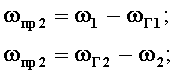
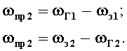
Следовательно, если частоты настройки ω1 и ω2 принять за основные каналы приема, то наряду с ними будут иметь место зеркальные каналы приема, частоты ω1 и ω2 которых отличаются от частот ω1 и ω2 на 2ωпр2 и расположены симметрично (зеркально) относительно частот гетеродинов ωГ1 и ωГ2 (фиг.4). Преобразование по зеркальным каналам приема происходит с тем же коэффициентом преобразования Кпр, что и по основным каналам приема. Поэтому они наиболее существенно влияют на избирательность и помехоустойчивость приемников.Therefore, if the tuning frequencies ω 1 and ω 2 are taken as the main reception channels, then along with them there will be mirror receiving channels, the frequencies ω 1 and ω 2 of which differ from the frequencies ω 1 and ω 2 by 2ω pr2 and are located symmetrically (mirror ) relative to the frequencies of the local oscillators ω G1 and ω G2 (figure 4). The conversion of the mirror channels of reception occurs with the same conversion coefficient K pr as the main channels of reception. Therefore, they most significantly affect the selectivity and noise immunity of receivers.
Кроме зеркальных существуют и другие дополнительные (комбинационные) каналы приема. В общем виде любой комбинационный канал приема имеет место при выполнении условий:In addition to mirrored, there are other additional (combination) reception channels. In general terms, any combination receive channel takes place when the following conditions are met:
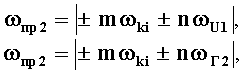
где ωki - частота i-го комбинированного канала приема, m, n , i - целые положительные числа.where ω ki is the frequency of the i-th combined receive channel, m, n, i are positive integers.
Наиболее вредные комбинационными каналами приема являются каналы, образующиеся при взаимодействии первой гармоники частоты сигнала с гармониками частот гетеродинов малого порядка (второй, третьей и т.д.), так как чувствительность приемников по этим каналам близка к чувствительности основных каналов. Так, четырем комбинационным каналам при m=1 и n=2 соответствуют частоты:The most harmful Raman reception channels are the channels formed by the interaction of the first harmonic of the signal frequency with the harmonics of the frequencies of small local oscillators (second, third, etc.), since the sensitivity of the receivers on these channels is close to the sensitivity of the main channels. So, four combination channels with m = 1 and n = 2 correspond to frequencies:

Наличие ложных сигналов (помех), принимаемых по зеркальным и комбинационным каналам, приводят к снижению помехоустойчивости и надежности дуплексной радиосвязи между пунктом управления воздушным движением и летательным аппаратом.The presence of false signals (interference) received via mirror and Raman channels leads to a decrease in noise immunity and reliability of duplex radio communication between an air traffic control center and an aircraft.
Технической задачей изобретения является повышение помехоустойчивости и надежности дуплексной радиосвязи между пунктом управления воздушным движением и летательным аппаратом путем подавления ложных сигналов (помех), принимаемых по зеркальным и комбинационным каналам.An object of the invention is to increase the noise immunity and reliability of duplex radio communication between an air traffic control center and an aircraft by suppressing false signals (interference) received via mirror and Raman channels.
Поставленная задача решается тем, что способ предотвращения несанкционированного использования летательных аппаратов, заключающийся, в соответствии с ближайшим аналогом, в том, что средствами пунктов управления воздушным движением определяют текущие координаты и параметры движения летательного аппарата, прогнозируют возможность нештатного изменения траектории его полета, формируют и передают на борт летательного аппарата команды на изменение параметров полета, при этом в процессе предполетной подготовки в бортовую навигационную систему летательного аппарата вводят детерминированные программные траекторные параметры с заложенной невозможностью из изменения, в процессе полета определение текущих координат и параметров движения летательного аппарата дополнительно производят собственными средствами летательного аппарата и средствами космического и воздушного наблюдения, информационно сопряженными с пунктами управления воздушным движением с постоянным определением указанными средствами рассогласования параметров текущей траектории летательного аппарата от детерминированной программной, по информации, размещенной в системе серверов баз обновляемых данных, информационно сопряженных с пунктами управления воздушным движением, об энергетическом потенциале летательного аппарата, о степени важности объектов, расположенных по траектории полета летательного аппарата и их взаимном положении в процессе полета, выявляют конфликтно-опасные летательные аппараты и отслеживают попытки несанкционированного использования выявленных конфликтно-опасных летательных аппаратов по информации об их недопустимом отклонении от детерминированной программной траектории или по тревожному сообщению с борта летательного аппарата, а при наступлении этого сообщения производят реконфигурацию бортовых систем или бортовой аппаратуры летательного аппарата по командам, сформированным бортовым корректирующим устройством, или по командам, сформированным и переданным на борт летательного аппарата указанными средствами наблюдения и пункты управления и снятие этой реконфигурации после уменьшения рассогласования до допустимой величины, при этом на борту летательного аппарата при его несанкционированном использовании формируют гармоническое колебание несущей частоты ωc, манипулируют его по фазе псевдослучайной последовательностью, которая является идентификационным номером летательного аппарата, сформированный сложный сигнал с фазовой манипуляцией преобразуют по частоте с использованием частоты ωГ1, первого гетеродина, выделяют напряжение первой промежуточной частоты, равной сумме частот ωпр1=ωс+ωГ1, усиливают его по мощности и излучают в эфир на частоте ω1=ωпр1=ωГ1, принимают сложный сигнал с фазовой манипуляцией на частоте ω1 на пункте управления воздушным движением, усиливают его по мощности, преобразуют по частоте с использованием частоты ωГ1 второго гетеродина, выделяют напряжение второй промежуточной частоты, равной разности частот ωпp2=ω1-ωГ1, выделяют низкочастотное напряжение, пропорциональное идентифицированному номеру летательного аппарата, регистрируют и анализируют его, на пункте управления воздушным движением формируют гармоническое колебание несущей частоты ωс, манипулируют его по фазе модулирующим кодом, отображающим команды на реконфигурацию бортовой аппаратуры летательного аппарата, преобразуют его по частоте с использованием частоты ωг2, первого гетеродина, выделяют напряжение третьей промежуточной частоты, равной разности частот ωпр3=ωг2-ωс, усиливают его по мощности и излучают в эфир на частоте ω2=ωпр3=ωг1, принимают сложный сигнал с фазовой манипуляцией на частоте ω2 на борту летательного аппарата, усиливают его по мощности, преобразуют по частоте с использованием частоты ωг2 второго гетеродина, выделяют первое напряжение второй промежуточной частоты, равной разности частот ωпр2=ωг2-ω2, выделяют низкочастотное напряжение, пропорциональное модулирующему коду, и используют его для реконфигурации бортовой аппаратуры летательного аппарата, причем частоты ωг1 и ωг2 гетеродинов разносят на величину второй промежуточной частоты ωг2-ωг1=ωпр2, на борту летательного аппарата сложные сигналы с фазовой манипуляцией излучают на частоте ω1 а принимают - на частоте ω2, а на пункте управления воздушным движением, наоборот, сложные сигналы с фазовой манипуляцией излучают на частоте ω2, а принимают - на частоте ω1, отличается от ближайшего аналога тем, что на борту летательного аппарата напряжение второго гетеродина сдвигают по фазе на -90°, используют его для повторного преобразования по частоте принимаемого сложного сигнала с фазовой манипуляцией на частоте ω2, выделяют второе напряжение второй промежуточной частоты, равной разности частот ωпр2=ωГ2-ω2, сдвигают его по фазе на +90°, суммируют с первым напряжением второй промежуточной частоты, перемножают первое суммарное напряжение с принимаемым сложным сигналом, выделяют гармоническое напряжение с частотой ωГ2, детектируют его, используют продетектированное напряжение для разрешения синхронного детектирования первого суммарного напряжения с использованием гармонического колебания несущей частоты ωс в качестве опорного напряжения, на пункте управления воздушным движением напряжение второго гетеродина сдвигают по фазе на +90°, используют его для повторного преобразования по частоте принимаемого сигнала с фазовой манипуляцией на частоте ω2, выделяют четвертое напряжение второй промежуточной частоты, равной разности частот ωпp2=ω1-ωГ1, сдвигают его по фазе на +90°, суммируют с третьим напряжением второй промежуточной частоты, перемножают второе суммарное напряжение с принимаемым сложным сигналом, выделяют гармоническое напряжение с частотой ωГ1, детектируют его, используют продетектированное напряжение для разрешения синхронного детектирования второго суммарного напряжения с использованием гармонического колебания несущей частоты ωс в качестве опорного напряжения.The problem is solved in that a way to prevent unauthorized use of aircraft, which, in accordance with the closest analogue, is that the air traffic control points determine the current coordinates and parameters of the aircraft’s movement, predict the possibility of an abnormal change in its flight path, form and transmit on board the aircraft crews to change flight parameters, while in the process of preflight preparation for on-board navigation the system of the aircraft is introduced with deterministic programmed trajectory parameters with the impossibility of changing; during the flight, the determination of the current coordinates and parameters of the aircraft’s movement is additionally carried out using the aircraft’s own means and space and airborne surveillance tools informationally coupled with the air traffic control points with constant determination by the indicated means mismatch of the parameters of the current trajectory of the aircraft and from the deterministic software, according to the information placed in the system of updated database servers, informationally coupled with air traffic control points, about the energy potential of the aircraft, about the importance of objects located along the flight path of the aircraft and their relative position during the flight, reveal conflict-dangerous aircraft and track attempts to unauthorized use of identified conflict-dangerous aircraft according to information about their an unacceptable deviation from the deterministic programmed trajectory or by an alarm message from the aircraft, and upon the occurrence of this message, reconfiguration of the aircraft’s onboard systems or aircraft’s equipment is performed according to the commands generated by the aircraft’s onboard correction device, or according to the commands generated and transmitted to the aircraft by the indicated means observation and control points and removal of this reconfiguration after reducing the mismatch to an acceptable value, with e the volume on board the aircraft during its unauthorized use form a harmonic oscillation of the carrier frequency ω c , manipulate it in phase with a pseudo-random sequence, which is the identification number of the aircraft, the generated complex signal with phase manipulation is converted in frequency using frequency ω G1 , the first local oscillator, isolated the voltage of the first intermediate frequency equal to the sum of the frequencies ω CR1 = ω s + ω G1 , amplify it in power and radiate it at the frequency ω 1 = ω CR1 = ω G1 , receive a complex signal with phase shift keying at frequency ω 1 at the air traffic control station, amplify it in power, convert it in frequency using frequency ω G1 of the second local oscillator, isolate the voltage of the second intermediate frequency equal to the frequency difference ω p2 = ω 1 -ω G1, isolated low-frequency voltage proportional to the identified number of the aircraft, recorded and analyzed, the air traffic control point forming a harmonic oscillation with the carrier frequency ω by manipulating T his code phase modulating reflecting reconfiguration commands on-board equipment of the aircraft, it is converted in frequency by using frequency ω r2, the first local oscillator is isolated voltage of the third intermediate frequency equal to the frequency difference PR3 ω = ω z2 -ω s, amplify it by and power emit broadcast at the frequency ω = ω 2 = ω r1 PR3, receiving a composite signal with a phase shift keying at frequency ω 2 on board the aircraft, increase its power, frequency-converted using a second frequency ω z2 geterod to, allocate the first voltage of the second intermediate frequency equal to the frequency difference np2 ω = ω z2 -ω 2, allocate a low-frequency voltage proportional to the modulating code and use it to reconfigure the board equipment of the aircraft, wherein the frequency ω d1 and ω z2 heterodyne spread by an amount second intermediate frequency ω z2 -ω d1 = ω np2, on board an aircraft complex signals with a phase shift keying radiate at frequency ω 1 and receiving - at frequency ω 2, and an air traffic control point on the contrary, complex B Nala phase shift keyed radiate at frequency ω 2, and receiving - at frequency ω 1 differs from the closest analog by the fact that on board the aircraft voltage of the second local oscillator is shifted in phase by -90 °, it is used to re-convert the frequency of the received complex signal with phase manipulation at a frequency of ω 2 , the second voltage of the second intermediate frequency is selected , equal to the frequency difference ω pr2 = ω G2 -ω 2 , it is shifted in phase by + 90 °, summed with the first voltage of the second intermediate frequency, the first sum is multiplied voltage with the received complex signal, emit a harmonic voltage with a frequency ω Г2 , detect it, use the detected voltage to enable synchronous detection of the first total voltage using harmonic oscillations of the carrier frequency ω s as a reference voltage, at the air traffic control point, the voltage of the second local oscillator is shifted in phase by + 90 °, it is used for re-transformation of the received signal with the phase frequency shift keying at a frequency ω 2, in fissioning fourth voltage of the second intermediate frequency equal to the frequency difference pp2 ω = ω 1 -ω G1, it is shifted in phase by + 90 °, the third voltage is added to the second intermediate frequency, the second sum voltage is multiplied with the received complex signal, allocate the harmonic voltage with frequency ω G1 , detect it, use the detected voltage to enable synchronous detection of the second total voltage using harmonic oscillations of the carrier frequency ω s as a reference voltage.
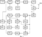
Техническая сущность способа поясняется фиг.1 на примере перелета пилотируемого ЛА (например, пассажирский дальнемагистральный самолет) из одного пункта в другой. Структурная схема бортовой аппаратуры ЛА представлена на фиг.2. Структурная схема аппаратуры, размещаемой на пункте управления воздушным движением, представлена на фиг.3. Частотная диаграмма, поясняющая преобразование сигналов по частоте, представлена на фиг.4.The technical essence of the method is illustrated in figure 1 by the example of a flight of a manned aircraft (for example, a passenger long-haul aircraft) from one point to another. The structural diagram of the on-board equipment of the aircraft is presented in figure 2. The structural diagram of the equipment placed at the air traffic control point, is presented in figure 3. A frequency diagram explaining the conversion of signals by frequency is shown in FIG. 4.
Бортовая аппаратура ЛА и аппаратура, размещаемая на пункте управления воздушным движением, содержит последовательно включенные задающий генератор 11.1 (11.2), фазовый манипулятор 13.1 (13.2), второй вход которого соединен с выходом генератора 12.1 псевдослучайной последовательности (ПСП) (генератора 12.2 модулирующего кода), первый смеситель 15.1 (15.2), второй вход которого соединен с выходом первого гетеродина 14.1 (14.2), усилитель 16.1 первой промежуточной (16.2 третьей промежуточной) частоты, первый усилитель 17.1 (17.2) мощности, дуплексер 18.1 (18.2), вход-выход которого связан с приемопередающей антенной 19.1 (19.2), второй усилитель 20.1 (20.2) мощности, второй смеситель 22.1 (22.2), второй вход которого соединен с выходом второго гетеродина 21. (21.2), первый усилитель 23.1 (третий усилитель 23.2) второй промежуточной частоты, сумматор 30.1 (30.2), перемножитель 31.1 (31.2), второй вход которого соединен с выходом второго усилителя 20.1 (20.2) мощности, узкополосный фильтр 32.1 (32.2), амплитудный детектор 33.1 (33.2), ключ 34.1 (34.2), второй вход которого соединен с выходом сумматора 30.1 (30.2), фазовый детектор 24.1 (24.2), второй вход которого соединен с выходом задающего генератора 11.1 (11.2), и блок 25.1 реконфигурации бортовой аппаратуры (блок 25.2 регистрации).The aircraft on-board equipment and the equipment located at the air traffic control center contain serially connected master oscillator 11.1 (11.2), a phase manipulator 13.1 (13.2), the second input of which is connected to the output of the pseudorandom sequence generator 12.1 (modulating code generator 12.2), the first mixer 15.1 (15.2), the second input of which is connected to the output of the first local oscillator 14.1 (14.2), the amplifier 16.1 of the first intermediate (16.2 third intermediate) frequency, the first amplifier 17.1 (17.2) power, the duplexer 18.1 (18.2), input-output of which connected to the transceiver antenna 19.1 (19.2), the second power amplifier 20.1 (20.2), the second mixer 22.1 (22.2), the second input of which is connected to the output of the second local oscillator 21. (21.2), the first amplifier 23.1 (third amplifier 23.2) of the second intermediate frequency , adder 30.1 (30.2), a multiplier 31.1 (31.2), the second input of which is connected to the output of the second power amplifier 20.1 (20.2), a narrow-band filter 32.1 (32.2), an amplitude detector 33.1 (33.2), a key 34.1 (34.2), the second input of which connected to the output of the adder 30.1 (30.2), a phase detector 24.1 (24.2), the second input of which is connected to the output the master oscillator house 11.1 (11.2), and the on-board equipment reconfiguration block 25.1 (registration block 25.2).
Предлагаемый способ реализуется следующим образом.The proposed method is implemented as follows.
Экипаж самолета 1, находящегося в аэропорту 2 (показана только взлетная полоса) с разрешения пункта 3 управления воздушным движением, обслуживающим данный аэропорт, готовится к перелету в аэропорт 4, который обслуживается пунктом 5 управления воздушным движением. Вдоль трассы полета могут находиться несколько таких пунктов, информационно взаимоувязанных друг с другом и с бортом сопровождаемого ими самолета в процессе его полета.The crew of aircraft 1 located at airport 2 (only the runway is shown) with the permission of
В процессе предполетной подготовки в вычислители бортовых навигационных систем вводят блоки памяти с размещенными в них детерминированными программными траекторными параметрами с заложенной невозможностью их изменения.In the process of preflight preparation, memory units with deterministic programmed trajectory parameters placed in them with the impossibility of changing them are introduced into the on-board navigation system calculators.
Следовательно, экипаж в процессе полета не имеет возможности каким-либо образом изменить заложенные траекторные параметры. Их изменение возможно только по инициативе пункта управления воздушным движением, в зоне управления которого в данный момент находится самолет (например, по радиоканалу), в случае обхода грозы, невозможности посадки в аэропорту пребывания по метеоусловиям, появления технических неисправностей. Такие же детерминированные траекторные параметры размещены в памяти вычислительных систем всех пунктов управления воздушным движением, размещенных в радиусе досягаемости ЛА данного типа. В общем случае в них же размещены детерминированные траекторные параметры всех ЛА, пребывающих в зоне видимости устойчивого информационного обмена в соответствии с расписанием и маршрутизацией полетов. Траекторные параметры, включая участки послевзлетных разворотов и маневрирования перед посадкой, могут задаваться в различной форме, например, совокупностью пар H(L), ψ(L) (текущая высота и ортодромный курс по дальности L), текущими координатами текущими X, Y, Z по дальности L или времени t в связанной с землей системой координат или в другой форме.Therefore, the crew during the flight does not have the ability to somehow change the incorporated trajectory parameters. Their change is possible only at the initiative of the air traffic control center, in the control zone of which the aircraft is currently located (for example, via a radio channel), in case of a thunderstorm circumvention, impossibility to land at the airport under weather conditions, and technical malfunctions. The same determinate trajectory parameters are located in the memory of computer systems of all air traffic control points located within the reach of an aircraft of this type. In the general case, they also contain the determined trajectory parameters of all aircraft that are in the visibility zone of stable information exchange in accordance with the flight schedule and routing. The trajectory parameters, including the areas of post-take-off turns and maneuvering before landing, can be set in various forms, for example, by a combination of pairs H (L), ψ (L) (current altitude and orthodrome course in range L), current coordinates, current X, Y, Z in range L or time t in a coordinate system connected with the earth or in another form.
После взлета самолета и начала его полета по детерминированной программной траектории средствами пунктов управления воздушным движением определяют текущие координаты и параметры движения ЛА и прогнозируют возможность нештатного изменения траектории полета по рассогласованию параметров текущей траектории ЛА от детерминированной программной на величину, более чем заранее заданная. При этом допускаемая величина рассогласования может быть переменной на различных участках траектории: на участке захода на посадку она должна быть меньше. В процессе полета определение текущих координат и параметров движения ЛА, а также выявление рассогласования между текущими и детерминированными программными траекторными параметрами дополнительно производятся его собственными бортовыми средствами и средствами космического (например, спутник разведки) и воздушного наблюдения (например, самолет типа «Авакс»).After the aircraft takes off and begins its flight along a deterministic programmed trajectory, the air traffic control points determine the current coordinates and parameters of the aircraft’s movement and predict the possibility of an abnormal change in the flight path by mismatching the parameters of the current aircraft trajectory from the deterministic program by more than a predetermined amount. In this case, the allowable value of the mismatch can be variable in different parts of the trajectory: in the approach area, it should be less. During the flight, the determination of the current coordinates and parameters of the aircraft’s movement, as well as the identification of the mismatch between the current and deterministic programmed trajectory parameters, is additionally carried out by its own on-board means and by means of space (for example, reconnaissance satellite) and aerial surveillance (for example, Avax type aircraft).
К собственным средствам определения текущих координат относится инерциальная навигационная система (ИНС) или аппаратура спутниковой навигационной системы. Предполагается также, что вычислительные системы средств воздушного и космического наблюдения тоже содержат детерминированные программные траекторные параметры ЛА, находящихся в зонах их видимости и устойчивого информационного обмена.Inertial navigation system (ANN) or satellite navigation system equipment is one of the own means of determining the current coordinates. It is also assumed that the computing systems of airborne and space surveillance equipment also contain deterministic programmed trajectory parameters of the aircraft located in the zones of their visibility and stable information exchange.
Как в зоне полета, так и в зоне досягаемой дальности ЛА, обладающего значительным энергетическим потенциалом (сотни тонн общей массы, десятки тонн топлива, большая скорость полета), расположено большое количество объектов различной степени важности, включая и объекты особой важности (объекты атомной и гидроэнергетики, учреждения государственной власти, пусковые установки с ядерными зарядами, склады и предприятия особо токсичной продукции, пункты управления, места проведения массовых мероприятий, крупные объекты на водной поверхности и др.), разрушение или уничтожение которых чревато необратимыми катастрофическими последствиями. Координаты этих объектов размещаются в серверах баз данных 6.Both in the flight zone and in the reachable range of an aircraft with significant energy potential (hundreds of tons of total mass, tens of tons of fuel, high flight speed), there are a large number of objects of varying degrees of importance, including objects of special importance (nuclear and hydropower facilities , government agencies, launchers with nuclear charges, warehouses and enterprises of particularly toxic products, control centers, venues for public events, large facilities on the water surface and etc.), the destruction or destruction of which is fraught with irreversible catastrophic consequences. The coordinates of these objects are located in database servers 6.
На борту ЛА 1, осуществляющего полет по траектории 8 с заданными детерминированными траекторными параметрами может произойти нештатная ситуация, следствием которой может стать появление сигнала о рассогласовании между текущими и детерминированными программными траекторными параметрами на величину, более чем заранее допустимую, что будет обнаружено бортовыми средствами ЛА, средствами пункта управления воздушным движением и средствами воздушного и космического наблюдения. Предположим, что это происходит в точке 9 траектории 8, и ЛА, перейдя на ручное управление, произвел несанкционированный разворот и по траектории 10 продолжил полет в направлении объекта особой важности 7. Появление отмеченного выше сигнала при отсутствии причины технического характера (например, по оперативному анализу телеметрируемых параметров) идентификация как попытка несанкционированного использования выявленного конфликтно-опасного ЛА (например, при захвате управления ЛА террористами). Эта попытка может быть идентифицирована также по тревожному сообщению экипажа ЛА до начала его несанкционированного разворота или в процессе взлета. При этом включается задающий генератор 11.1, который формирует высокочастотное колебаниеAn abnormal situation may occur on board the aircraft 1 flying along trajectory 8 with the given deterministic trajectory parameters, which may result in the appearance of a signal about the mismatch between the current and deterministic program trajectory parameters by an amount more than previously admissible, which will be detected by the aircraft's onboard means, by means of an air traffic control center and by means of air and space observation. Suppose that this happens at point 9 of trajectory 8, and the aircraft, having switched to manual control, made an unauthorized turn and continued along the path 10 in the direction of the object of special importance 7. The signal noted above appears in the absence of a technical reason (for example, operational analysis telemetry parameters) identification as an attempt to unauthorized use of the identified conflict-dangerous aircraft (for example, when seizing control of an aircraft by terrorists). This attempt can also be identified by an alarm message from the aircraft crew before the start of its unauthorized turn or during take-off. In this case, the master oscillator 11.1 is turned on, which generates a high-frequency oscillation
uc1(t)=Uc1cos(ωct+φc), 0≤t≤Tc1 u c1 (t) = U c1 cos (ω c t + φ c ), 0≤t≤T c1
где Uc1, ωc, φc, Тc1 - амплитуда, несущая частота, начальная фаза и длительностьwhere U c1 , ω c , φ c , T c1 - amplitude, carrier frequency, initial phase and duration
высокочастотного колебания,high frequency oscillation
которое поступает на первый вход фазового манипулятора 13.1. На второй вход фазового манипулятора 13.1 подается псевдослучайная последовательность (ПСП) с выхода генератора 12.1 ПСП, которая является идентификационным номером ЛА. На выходе фазового манипулятора 13.1 образуется сложный сигнал с фазовой манипуляцией (ФМн)which goes to the first input of the phase manipulator 13.1. The second input of the phase manipulator 13.1 is fed a pseudo-random sequence (PSP) from the output of the generator 12.1 PSP, which is the identification number of the aircraft. At the output of the phase manipulator 13.1, a complex signal with phase shift keying (PSK) is formed
u1(t)=UГ1cos[ωct+φk1(t)+φc1], 0≤t≤Tc1,u 1 (t) = U Г1 cos [ω c t + φ k1 (t) + φ c1 ], 0≤t≤T c1 ,
где φk1(t)={0,π} - манипулированная составляющая фазы, отображающая закон фазовой манипуляции в соответствии с идентификационным номером ЛА,where φ k1 (t) = {0, π} is the manipulated component of the phase, which displays the law of phase manipulation in accordance with the identification number of the aircraft,
который поступает на первый вход первого смесителя 15.1, на второй вход которого подается напряжение первого гетеродина 14.1which is fed to the first input of the first mixer 15.1, the second input of which is supplied with the voltage of the first local oscillator 14.1
UГ1(t)=UГ1cos(ωГ1t+φГ1).U Г1 (t) = U Г1 cos (ω Г1 t + φ Г1 ).
На выходе смесителя 15.1 образуется напряжение комбинационных частот. Усилителем 16.1 выделяется напряжение первой промежуточной частотыAt the output of the mixer 15.1, a voltage of combination frequencies is generated. Amplifier 16.1 distinguishes the voltage of the first intermediate frequency
uпр1(t)=Uпр1cos[ωпр1t+φk1(t)+φпр1],u CR1 (t) = U CR1 cos [ω CR1 t + φ k1 (t) + φ CR1 ],
где ![]()
![]()
ωпр1=ωс+ωГ1=ω1 - первая промежуточная (суммарная) частота (фиг.4);ω pr1 = ω s + ω G1 = ω 1 - the first intermediate (total) frequency (figure 4);
φпр1=φГ1+φc;φ CR1 = φ G1 + φ c ;
которое после усиления в усилителе 17,1 мощности через дуплексер 18.1 поступает в приемопередающую антенну 19.1, излучается ею в эфир, улавливается приемопередающей антенной 19.2 пункта управления воздушным движением и через дуплексер 18.2 и усилитель 20.2 мощности поступает на первые входы смесителей 22.2 и 27.2, на вторые входы которых подаются напряжения гетеродина 21.2which, after amplification in the power amplifier 17.1 through the duplexer 18.1, enters the transceiver antenna 19.1, is radiated by it, is captured by the transceiver antenna 19.2 of the air traffic control station, and through the duplexer 18.2 and the power amplifier 20.2 goes to the first inputs of the mixers 22.2 and 27.2, to the second the inputs of which the voltage of the local oscillator 21.2
uг1(t)=UГ1cos(ωГ1t+φГ1),u g1 (t) = U Г1 cos (ω Г1 t + φ Г1 ),
uГ1(t)=UГ1cos(ωГ1t+φГ1+90°).u Г1 (t) = U Г1 cos (ω Г1 t + φ Г1 + 90 °).
На выходе смесителей 22.2 и 27.2 образуются напряжения комбинационных частот. Усилителями 23.2 и 28.2 выделяются напряжения второй промежуточной (разностной) частоты:At the output of the mixers 22.2 and 27.2, voltages of combination frequencies are generated. Amplifiers 23.2 and 28.2 distinguish the voltage of the second intermediate (difference) frequency:
uпр2(t)=Uпр2cos[ωпр2t+φk1(t)+φпр2],u CR2 (t) = U CR2 cos [ω CR2 t + φ k1 (t) + φ CR2 ],
uпр3(t)=Uпр2cos[ωпр2t+φk1(t)+φпр2-90°],u CR3 (t) = U CR2 cos [ω CR2 t + φ k1 (t) + φ CR2 -90 °],
где ![]()
![]()
ωпр2=ωпр1-ωГ1 - вторая промежуточная (разностная) частота;ω CR2 = ω CR1- ω G1 - the second intermediate (difference) frequency;
φпр2=φпр1-φГ1. φ pr2 = φ pr1 -φ G1.
Напряжение uпр3(t) с выхода усилителя 28.2 второй промежуточной частоты поступает на вход фазовращателя на 29.2 на 90°, на выходе которого образуется напряжениеThe voltage u pr3 (t) from the output of the amplifier 28.2 of the second intermediate frequency is fed to the input of the phase shifter at 29.2 by 90 °, at the output of which a voltage is generated
uпp4(t)=Uпp2сos[ωпр2t+φk1(t)+φпр2-90°+90°]=Uпр2cos[ωпр2t+φk1(t)+φпр2].u pp4 (t) = U pp2 cos [ω CR2 t + φ k1 (t) + φ CR2 -90 ° + 90 °] = U CR2 cos [ω CR2 t + φ k1 (t) + φ CR2 ].
Напряжения uпр2(t) и uпр4(t) поступают на два входа сумматора 30.2, на выходе которого образуется второе суммарное напряжение u∑2(t)=U∑2cos[ωпр2t+φk1(t)+φпр2], 0≤t≤Tc1 Voltages u CR2 (t) and u CR4 (t) are supplied to two inputs of the adder 30.2, at the output of which a second total voltage u ∑2 (t) = U ∑2 cos [ω CR2 t + φ k1 (t) + φ CR2 ], 0≤t≤T c1
где U∑2=2Uпр2;where U ∑2 = 2U pr2 ;
которое поступает на второй вход перемножителя 31.2. На первый вход последнего подается принимаемый сигнал uпр1(t) с выхода усилителя 20.2 мощности. На выходе перемножителя 31.2 образуется гармоническое напряжениеwhich goes to the second input of the multiplier 31.2. The received signal u pr1 (t) from the output of the power amplifier 20.2 is fed to the first input of the latter. At the output of the multiplier 31.2 a harmonic voltage is generated
u2(t)=U2cos(ωГ1t+φГ1),u 2 (t) = U 2 cos (ω Г1 t + φ Г1 ),
где ![]()
![]()
которое выделяется узкополосным фильтром 32.2, детектируется амплитудным детектором 33.2 и подается на управляющий вход ключа 34.2, открывая его. В исходном состоянии ключ 34.2 всегда закрыт.which is allocated by the narrow-band filter 32.2, is detected by the amplitude detector 33.2 and is supplied to the control input of the key 34.2, opening it. In the initial state, key 34.2 is always closed.
Частота настройки ωн1 узкополосного фильтра 32.2 выбирается следующим образом: ωн1=ωГ2. При этом суммарное напряжение u∑2(t) с выхода сумматора 30.2 через открытый ключ 34.2 подается на первый (информационный) вход фазового детектора 24.2. На второй (опорный) вход фазового детектора 24.2 подается напряжениеThe tuning frequency ω n1 of the narrow-band filter 32.2 is selected as follows: ω n1 = ω G2 . In this case, the total voltage u ∑2 (t) from the output of the adder 30.2 through the public key 34.2 is supplied to the first (information) input of the phase detector 24.2. A voltage is applied to the second (reference) input of the phase detector 24.2
uc2(t)=Uc2cos(ωct+φc), 0≤t≤Tc2,u c2 (t) = U c2 cos (ω c t + φ c ), 0≤t≤T c2 ,
с выхода задающего генератора 11.2. В результате синхронного детектирования на выходе фазового детектора 24.2 образуется низкочастотное напряжениеfrom the output of the master oscillator 11.2. As a result of synchronous detection, a low-frequency voltage is generated at the output of the phase detector 24.2
uн1(t)=Uн1cosφk1(t),u н1 (t) = U н1 cosφ k1 (t),
где ![]()
![]()
которое фиксируется блоком 25.2 регистрации.which is fixed by the block 25.2 registration.
По зафиксированному низкочастотному напряжению определяется идентификационный номер ЛА, захваченного террористами, и его местоположение. При этом высокочастотное колебание uc2(t) с выхода задающего генератора 11.2 поступает на первый вход фазового манипулятора 13.2, на второй вход которого подается модулирующий код M(t) с выхода генератора 12.2. На выходе фазового манипулятора 13.2 образуется сложный ФМн-сигналAccording to the recorded low-frequency voltage, the identification number of the aircraft captured by the terrorists and its location are determined. In this case, the high-frequency oscillation u c2 (t) from the output of the master oscillator 11.2 is fed to the first input of the phase manipulator 13.2, the second input of which is supplied with the modulating code M (t) from the output of the generator 12.2. At the output of the phase manipulator 13.2, a complex QPSK signal is formed
u2(t)=Uc2cos[ωct+φk2(t)+φc], 0≤t≤Tc2,u 2 (t) = U c2 cos [ω c t + φ k2 (t) + φ c ], 0≤t≤T c2 ,
где φk2(t)={0,π} - манипулируемая составляющая фазовой манипуляции в соответствии с модулирующим кодом M(t);where φ k2 (t) = {0, π} is the manipulated component of phase manipulation in accordance with the modulating code M (t);
который поступает на первый вход смесителя 15.2, на второй вход которого подается напряжение гетеродина 14.2which goes to the first input of the mixer 15.2, the second input of which is the voltage of the local oscillator 14.2
uг2(t)=Uг2cos(ωг2t+φг2).u g2 (t) = U g2 cos (ω g2 t + φ g2 ).
На выходе смесителя 15.2 образуются напряжения комбинационных частот. Усилителем 16.2 выделяется напряжение третьей промежуточной частотыAt the output of the mixer 15.2, voltages of combination frequencies are generated. Amplifier 16.2 distinguishes the voltage of the third intermediate frequency
uпр3(t)=Uпр3cos[ωпр3t-φk2(t)+φпр3], 0≤t≤Tc2 u CR3 (t) = U CR3 cos [ω CR3 t-φ k2 (t) + φ CR3 ], 0≤t≤T c2
где ![]()
![]()
ωпр3=ωu2-ωс - третья промежуточная частота;ω pr3 = ω u2 -ω s is the third intermediate frequency;
φпр3=φг2-φс, PR3 cp = φ -φ r2 with,
которое после усиления в усилителе 17.2 мощности через дуплексер 18.2 поступает в приемопередающую антенну 19.2, излучается ею в эфир на частоте ω2, улавливаются приемопередающей антенной 19.1 летательного аппарата и через дуплексер 18.1 и усилитель 20.1 мощности поступает на первые входы смесителей 22.1 и 27.1, на вторые входы которых подаются напряжения гетеродина 21.1:which, after amplification in the power amplifier 17.2 through the duplexer 18.2, enters the transceiver antenna 19.2, is radiated by it at the frequency ω 2 , it is captured by the transceiver antenna 19.1 of the aircraft and through the duplexer 18.1 and the power amplifier 20.1 goes to the first inputs of the mixers 22.1 and 27.1, to the second the inputs of which the voltage of the local oscillator 21.1 is supplied:
uГ2(t)=UГ2cos(ωГ2t+φГ2),u Г2 (t) = U Г2 cos (ω Г2 t + φ Г2 ),
![]()
![]()
На выходе смесителей 22.1 и 27.1 образуются напряжения комбинационных частот. Усилителями 23.1 и 28.1 выделяются напряжения второй промежуточной (разностной) частоты:At the output of the mixers 22.1 and 27.1, voltages of combination frequencies are generated. Amplifiers 23.1 and 28.1 distinguish the voltage of the second intermediate (difference) frequency:
uпр5(t)=Uпр5cos[ωпр2t+φk2(t)+φпр5],u CR5 (t) = U CR5 cos [ω CR2 t + φ k2 (t) + φ CR5 ],
uпр6(t)=Uпр5cos[ωпр2t+φk2(t)+φпр5-90°],u CR6 (t) = U CR5 cos [ω CR2 t + φ k2 (t) + φ CR5 -90 °],
где ![]()
![]()
ωпр2=ωГ2-ωпр3 - вторая промежуточная (разностная) частота;ω CR2 = ω G2- ω CR3 - the second intermediate (difference) frequency;
φпр5=φГ2-φпр3.φ pr5 = φ Г2 -φ pr3 .
Напряжение uпр6(t) с выхода усилителя 28.1 второй промежуточной частоты поступает на вход фазовращателя 29.1 на -90°, на выходе которого образуется напряжениеThe voltage u pr6 (t) from the output of the amplifier 28.1 of the second intermediate frequency is supplied to the input of the phase shifter 29.1 by -90 °, at the output of which a voltage is generated
uпр7(t)=Uпр5cos[ωпр2t+φk2(t)+φпр5-90°+90°]=Uпр5cos[ωпр2t+φk2(t)+φпр5].u PR7 (t) = U CR5 cos [ω CR2 t + φ k2 (t) + φ CR5 -90 ° + 90 °] = U CR5 cos [ω CR2 t + φ k2 (t) + φ CR5 ].
Напряжения uпр5(t) и uпр7(t) поступают на два входа сумматора 30.1, на выходе которого образуется первое суммарное напряжениеVoltages u CR5 (t) and u CR7 (t) are supplied to two inputs of the adder 30.1, at the output of which the first total voltage is formed
u∑1(t)=U∑cos[ωпр2t+φk2(t)+φпр6], 0≤t≤Tc,u ∑1 (t) = U ∑ cos [ω CR2 t + φ k2 (t) + φ CR6 ], 0≤t≤T c ,
где U∑1=2Uпр5,where U ∑1 = 2U pr5 ,
которое поступает на второй вход перемножителя 31.1. На первый вход последнего подается принимаемый сигнал uпр3(t) с выхода усилителя 20.1 мощности. На выходе перемножителя 31.1 образуется гармоническое напряжениеwhich goes to the second input of the multiplier 31.1. At the first input of the latter, a received signal u pr3 (t) is supplied from the output of the power amplifier 20.1. At the output of the multiplier 31.1, a harmonic voltage is generated
u3(t)=U3cos(ωГ2t+φГ2),u 3 (t) = U 3 cos (ω Г2 t + φ Г2 ),
где ![]()
![]()
которое выделяется узкополосным фильтром 32.1, детектируется амплитудным детектором 33.1 и подается на управляющий вход ключа 34.1, открывая его. В исходном состоянии ключ 34.1 всегда закрыт. Частота настройки ωН2 узкополосного фильтра 32.1 выбирается следующим образом: ωH2=ωГ2. При этом суммарное напряжение u∑1(t) с выхода сумматора 30.1 через открытый ключ 34.1 поступает на первый (информационный) вход фазового детектора 24.1. На второй (опорный) вход фазового детектора 24.1 подается напряжение uс1(t) с выхода задающего генератора 11.1.which is allocated by the narrow-band filter 32.1, is detected by the amplitude detector 33.1 and is supplied to the control input of the key 34.1, opening it. In the initial state, key 34.1 is always closed. The tuning frequency ω H2 of the narrow-band filter 32.1 is selected as follows: ω H2 = ω G2 . In this case, the total voltage u ∑1 (t) from the output of the adder 30.1 through the public key 34.1 is supplied to the first (information) input of the phase detector 24.1. The second (reference) input of the phase detector 24.1 is supplied with voltage u с1 (t) from the output of the master oscillator 11.1.
В результате синхронного детектирования на выходе фазового детектора 24.1 образуется низкочастотное напряжениеAs a result of synchronous detection, a low-frequency voltage is generated at the output of the phase detector 24.1
uн2(t)=Uн2cosφk2(t),u n2 (t) = U n2 cosφ k2 (t),
где ![]()
![]()
которое поступает в блок 25.1 реконфигурации бортовой аппаратуры.which enters the block 25.1 reconfiguration of on-board equipment.
Блок 25.1 может выполнять следующие виды реконфигурации бортовой аппаратуры ЛА:Block 25.1 may perform the following types of reconfiguration of aircraft onboard equipment:
- введение блокировки гидромеханической части системы штурвального управления;- the introduction of blocking the hydromechanical part of the steering control system;
- отключение системы распознавания «свой-чужой». Этим достигается выделение конфликтно-опасного ЛА в воздушном пространстве среди большого количества других ЛА с целью упорядоченной концентрации на нем внимания пунктов управления воздушным движением, средств ПВО и истребительной авиации;- disable the recognition system "friend or foe". This achieves the allocation of conflict-hazardous aircraft in the airspace among a large number of other aircraft in order to orderly concentrate on it the attention of air traffic control points, air defense systems and fighter aircraft;
- включение блока колебательности в автомате стабилизации, что приведет к раскачиванию ЛА по всем осям до границы его неустойчивости, затруднению пилотирования ЛА и наведению его на объект;- the inclusion of the block of oscillation in the stabilization machine, which will lead to the rocking of the aircraft in all axes to the boundary of its instability, the difficulty of piloting the aircraft and pointing it at the object;
- включение блоков искажения в системах построения курса, тангажа, например, циклическим суммированием с переменной по величине и времени установкой. Это обстоятельство приведет к потере ориентировки в пространстве и усложнит поиск объекта нанесения таранного удара;- the inclusion of blocks of distortion in the systems for constructing the course, pitch, for example, by cyclic summation with a variable installation in magnitude and time. This circumstance will lead to a loss of orientation in space and complicate the search for the target of ramming;
- включение блока искажения в системах измерения высоты и скорости, что затрудняет пилотирование ЛА;- the inclusion of a distortion unit in systems for measuring altitude and speed, which makes it difficult to pilot the aircraft;
- включение блока искажения в системе отображения полетной информации на приборной доске пилотов (углы атаки и скольжения, обороты двигателей и др.), например «мерцанием» показаний;- inclusion of a distortion block in the flight information display system on the pilots dashboard (attack and slip angles, engine speed, etc.), for example, by “flickering” of readings;
- принудительное включение системы аварийной сигнализации о нештатном функционировании всех жизненно важных систем ЛА. Это обстоятельство повлечет стрессовое состояние экипажа с потерей глубины логических действий с возможным последующим отказом от несанкционированных действий;- forced inclusion of the emergency alarm system about the abnormal functioning of all vital aircraft systems. This circumstance will entail the stressful state of the crew with the loss of the depth of logical actions with the possible subsequent rejection of unauthorized actions;
- отключение одного или группы двигателей, а также включение системы аварийного слива топлива, что затрудняет пилотирование ЛА и уменьшает его досягаемую дальность полета;- turning off one or a group of engines, as well as turning on the emergency fuel drain system, which complicates the piloting of the aircraft and reduces its reachable flight range;
- включение блока отрицательного мультимедиа воздействия (звуковое сопровождение на частотах, неблагоприятно воздействующих на слуховой аппарат, а также выведение на бортовой дисплей изображений, неприятных для ощущений террористам). Это обстоятельство повлечет стрессовое состояние экипажа с потерей полноты логических действий;- inclusion of a block of negative multimedia effects (sound accompaniment at frequencies that adversely affect the hearing aid, as well as displaying images on the on-board display that are unpleasant for terrorists to sense). This circumstance will entail the stressful state of the crew with the loss of completeness of logical actions;
- включение блока выдачи рекомендаций экипажу, например включение изображения главы террористической организации, приказывающего прекратить несанкционированные действия;- inclusion of a block for issuing recommendations to the crew, for example, inclusion of an image of the head of a terrorist organization ordering to stop unauthorized actions;
- включение блока перевода управления в режим дистанционного пилотирования (например, на самолет сопровождения или пункт управления воздушным движением);- inclusion of the control transfer unit in the remote piloting mode (for example, to an escort aircraft or air traffic control center);
- включение систем придания непрозрачности остеклению кабины путем поляризации остекления, внутреннего или внешнего его забрызгивания, а также принудительное ослепление экипажа. Особенно эффективно это действие на начальной стадии взлета, когда несанкционированное использование ЛА может быть исключено в принципе;- the inclusion of systems to give opacity to the glazing of the cabin by polarizing the glazing, its internal or external splashing, as well as the compelling blindness of the crew. This action is especially effective at the initial stage of take-off, when unauthorized use of the aircraft can be excluded in principle;
- принудительную механическую фиксацию частей тела экипажа, что может затруднить ручное пилотирование ЛА или исключить переход на ручное управление перетягиванием штурвала;- forced mechanical fixation of the parts of the crew’s body, which may complicate manual piloting of the aircraft or preclude the transition to manual control of the tug of war;
- включение блока принудительного сваливания в штопор, например, путем одновременного формирования сигналов на реверс или отключение двигателей, но рули высоты (для увеличения угла атаки), крена и курса. Это действие является одним из последних, когда обнаружиться неизбежность столкновения ЛА с объектом особой ценности при исчерпании всех других, но подобная операция выполняется по команде с пункта управления воздушным движением по принятию соответствующего решения при лимите времени на задействование средств ПВО и истребительной авиации.- inclusion of a forced stall block in a tailspin, for example, by simultaneously generating signals to reverse or turn off the engines, but elevators (to increase the angle of attack), roll and course. This action is one of the last when it is inevitable that an aircraft collides with an object of special value when all the others are exhausted, but such an operation is carried out on command from the air traffic control center to make an appropriate decision with a time limit on the use of air defense and fighter aircraft.
Последовательность выдачи команд на виды реконфигурации бортовых систем или бортовой аппаратуры определяется мерой усиления эффекта их последствия. Причем эта последовательность команд может формироваться на средствах наземного базирования, на пунктах управления воздушным движением, а также на борту самого ЛА, подвергнутого попытке несанкционированного использования (кроме команды на принудительное сваливание в штопор).The sequence of issuing commands on the types of reconfiguration of on-board systems or on-board equipment is determined by the measure of enhancing the effect of their consequences. Moreover, this sequence of commands can be formed on ground-based facilities, at air traffic control points, as well as on board the aircraft itself, subjected to an attempt of unauthorized use (except for the command for compulsory stalling).
Следовательно, на борту ЛА размещен блок 25.1 реконфигурации, информационно сопряженный с элементами бортовой аппаратуры и бортовых систем, формирующий последовательность команд при появлении недопустимого рассогласования между текущими и детерминированными траекторными параметрами. При этом следует отметить, что при уменьшении рассогласования до допустимой величины (что можно трактовать как отказ экипажа от несанкционированных действий) ранее выданные команды на реконфигурацию бортовой аппаратуры и бортовых систем снимаются.Therefore, on board the aircraft there is a reconfiguration block 25.1, informationally coupled with elements of the on-board equipment and on-board systems, forming a sequence of commands when an unacceptable mismatch occurs between the current and deterministic trajectory parameters. It should be noted that when the discrepancy is reduced to an acceptable value (which can be interpreted as the crew refuses unauthorized actions), previously issued commands for reconfiguring the on-board equipment and on-board systems are removed.
Описанная выше работа устройства, реализующего предлагаемый способ, соответствует случаю приема полезных ФМн-сигналов по основному каналу на частотах ω1 и ω2.The above operation of the device that implements the proposed method corresponds to the case of receiving useful QPSK signals through the main channel at frequencies ω 1 and ω 2 .
Если ложный сигнал (помеха) поступает по первому зеркальному каналу на частоте ωЗ1 If a false signal (interference) enters the first mirror channel at a frequency ω З1
uЗ1(t)=UЗ1cos(ωЗ1t+φЗ1), 0≤t≤TЗ1, Z1 u (t) = U Z1 cos (ω t + φ P1 P1), 0≤t≤T P1,
то усилителями 23.2 и 28.2 второй промежуточной частоты выделяются следующие напряжения:the amplifiers 23.2 and 28.2 of the second intermediate frequency distinguish the following voltages:
uпр8(t)=Uпр8cos(ωпр2t+φпр8),u CR8 (t) = U CR8 cos (ω CR2 t + φ CR8 ),
uпр9(t)=Uпр8cos(ωпр2t+φпр8+90°), 0≤t≤TЗ1 pr9 u (t) = U pr8 cos (ω t + φ np2 pr8 + 90 °), 0≤t≤T P1
где ![]()
![]()
ωпр2=ωГ1-ωЗ1 - вторая промежуточная (разностная) частота,ω CR2 = ω G1 -ω Z1 - the second intermediate (difference) frequency,
φпр8=φГ1-φЗ1. pr8 cp = φ G1 -φ P1.
Напряжение Uпр9(t) с выхода усилителя 28.1 второй промежуточной частоты поступают на вход фазовращателя 29.2 на +90°, на выходе которого формируется напряжениеThe voltage U pr9 (t) from the output of the amplifier 28.1 of the second intermediate frequency is supplied to the input of the phase shifter 29.2 by + 90 °, at the output of which a voltage is formed
Uпр10(t)=Uпр8cos(ωпр2t+φпр8+90°+90°)=-Uпр8cos(ωпр2t+φпр8).U pr10 (t) = U pr8 cos (ω pr2 t + φ pr8 + 90 ° + 90 °) = - U pr8 cos (ω pr2 t + φ pr8 ).
Напряжения uпр8(t) и uпр10(t) поступают на два входа сумматора 30.3, на его выходе компенсируются.Voltages u CR8 (t) and u CR10 (t) are supplied to the two inputs of the adder 30.3, at its output are compensated.
Следовательно, ложный сигнал (помеха), принимаемый по первому зеркальному каналу на частоте ωЗ1, подавляется внешним кольцом, состоящим из гетеродина 21.2, фазовращателей 26.2 и 29.2 на +90°, смесителей 22.2 и 27.2, усилителей 23.2 и 28.2 второй промежуточной частоты, сумматора 30.2 и реализующим фазокомпенсационный метод.Therefore, a false signal (interference) received through the first mirror channel at a frequency of ω З1 is suppressed by an external ring consisting of a local oscillator 21.2, phase shifters 26.2 and 29.2 + 90 °, mixers 22.2 and 27.2, amplifiers 23.2 and 28.2 of the second intermediate frequency, adder 30.2 and implements phase compensation method.
Если ложный сигнал (помеха) поступает по второму зеркальному каналу на частоте ωЗ2 If a false signal (interference) enters the second mirror channel at a frequency ω З2
uЗ2(t)=UЗ2cos(ωЗ2t+φP2), 0≤t≤TЗ2,u З2 (t) = U З2 cos (ω З2 t + φ P2 ), 0≤t≤T З2 ,
то усилителями23.1 и 28.1 второй промежуточной частоты выделяются следующие напряжения:the amplifiers 23.1 and 28.1 of the second intermediate frequency distinguish the following voltages:
uпр11(t)=Uпр11cos(ωпр2t+φпр11),u pr11 (t) = U pr11 cos (ω pr2 t + φ pr11 ),
uпр12(t)=Uпр11cos(ωпр2t+φпр11+90°),u pr12 (t) = U pr11 cos (ω pr2 t + φ pr11 + 90 °),
где ![]()
![]()
ωпр2=ωЗ2-ωЗ2 - вторая промежуточная (разностная) частота, np2 ω = ω P2 -ω Z2 - second intermediate (difference) frequency,
φпр11=φЗ2-φЗ2.φ pr11 = φ З2 -φ З2 .
Напряжение Uпр12(t) с выхода усилителя 28.1 второй промежуточной частоты поступает на вход фазовращателя 29.1 на +90°, на выходе которого формируется напряжениеThe voltage U pr12 (t) from the output of the amplifier 28.1 of the second intermediate frequency is supplied to the input of the phase shifter 29.1 by + 90 °, at the output of which a voltage is formed
uпр13(t)=Uпр11cos(ωпр2t+φпр11+90°+90°)=-Uпр11cos(ωпр2t+φпр11).u pr13 (t) = U pr11 cos (ω pr2 t + φ pr11 + 90 ° + 90 °) = - U pr11 cos (ω pr2 t + φ pr11 ).
Напряжения uпр11(t) и uпр13(t), поступающие на два входа сумматора 30.1, на его выходе компенсируются.The voltages u pr11 (t) and u pr13 (t) supplied to the two inputs of the adder 30.1 are compensated at its output.
Следовательно, ложный сигнал (помеха), принимаемый по второму зеркальному каналу на частоте ωЗ2, подавляется внешним кольцом, состоящим из гетеродина 21.1, фазовращателя 26.1 на -90°, фазовращателя 29.1 на -90°, смесителей 22.1 и 27.1, усилителей 23.1 и 28.1 второй промежуточной частоты, сумматора 30.1 и реализующим фазокомпенсационный метод.Therefore, a false signal (interference) received via the second mirror channel at a frequency of ω З2 is suppressed by an external ring consisting of a local oscillator 21.1, a phase shifter 26.1 by -90 °, a phase shifter 29.1 by -90 °, mixers 22.1 and 27.1, amplifiers 23.1 and 28.1 the second intermediate frequency, the adder 30.1 and implements phase-compensation method.
По аналогичной причине подавляются и ложные сигналы (помехи), принимаемые по первому ωк1 и четвертому ωк4 комбинационным каналам.For a similar reason, false signals (interference) received through the first ω k1 and fourth ω k4 combinational channels are also suppressed.
Если ложный сигнал (помеха) принимается по второму комбинационному каналу на частоте ωк2 If a false signal (interference) is received on the second combination channel at a frequency ω k2
uK2(t)=UK2cos(ωK2t+φK2), 0≤t≤TK2,u K2 (t) = U K2 cos (ω K2 t + φ K2 ), 0≤t≤T K2 ,
то усилителями 23.2 и 28.2 второй промежуточной частоты выделяются следующие напряжения:the amplifiers 23.2 and 28.2 of the second intermediate frequency distinguish the following voltages:
uпр14(t)=Uпр14cos(ωпр2t+φпр14),u CR14 (t) = U CR14 cos (ω CR2 t + φ CR14 ),
uпр15(t)=Uпр14cos(ωпр2t+φпр14-90°),u pr15 (t) = U pr14 cos (ω pr2 t + φ pr14 -90 °)
где ![]()
![]()
ωпр2=ωК2-2ωГ1 - вторая промежуточная (разностная)частота,ω CR2 = ω K2 -2ω G1 - the second intermediate (difference) frequency,
φпр14=φК2-φГ1.φ pr14 = φ K2 -φ G1 .
Напряжение uпр15(t) с выхода усилителя 28.2 второй промежуточной частоты поступает на вход фазовращателя 29.2 на +90°, на выходе которого формируется напряжениеThe voltage u pr15 (t) from the output of the amplifier 28.2 of the second intermediate frequency is supplied to the input of the phase shifter 29.2 by + 90 °, at the output of which a voltage is formed
uпр16(t)-Uпр14cos(ωпр2t+φпр14-90°+90°)=Uпр14cos(ωпр2t+φпр14).u pr16 (t) -U pr14 cos (ω pr2 t + φ pr14 -90 ° + 90 °) = U pr14 cos (ω pr2 t + φ pr14 ).
Напряжения uпр14(t) и uпр16(t) поступают на два входа сумматора 30.1, на выходе которого образуется суммарное напряжениеVoltages u pr14 (t) and u pr16 (t) are supplied to two inputs of the adder 30.1, at the output of which the total voltage is formed
u∑3(t)=U∑3cos(ωпр2t+φпр14), 0≤t≤Tk2,u ∑3 (t) = U ∑3 cos (ω CR2 t + φ CR14 ), 0≤t≤T k2 ,
где U∑3=2Uпр14,where U ∑3 = 2U pr14 ,
которое поступает на второй вход перемножителя 31.2. На первый вход последнего подается принимаемый ложный сигнал (помеха) uk2(t) с выхода усилителя 20.2 мощности. На выходе перемножителя 31.2 образуется гармоническое напряжениеwhich goes to the second input of the multiplier 31.2. The first input of the latter receives the received false signal (interference) u k2 (t) from the output of the power amplifier 20.2. At the output of the multiplier 31.2 a harmonic voltage is generated
u4(t)=U4cos(2ωГ1t+φГ1), 0≤t≤Tk2,u 4 (t) = U 4 cos (2ω t + φ G1 G1), 0≤t≤T k2,
где ![]()
![]()
которое попадает в полосу пропускания узкополосного фильтра 32.2. Ключ 34.2 не открывается и ложный сигнал (помеха), принимаемый по второму комбинационному каналу на частоте ωк2, подавляется. Для этого используется «внутреннее кольцо», состоящее из перемножителя 31.2, узкополосного фильтра 32.2, амплитудного детектора 33.2, ключа 34.2 и реализующее метод узкополосной фильтрации.which falls into the passband of the narrow-band filter 32.2. Key 34.2 does not open and a false signal (interference) received on the second combination channel at a frequency ω k2 is suppressed. For this, an “inner ring” is used, consisting of a multiplier 31.2, a narrow-band filter 32.2, an amplitude detector 33.2, a key 34.2 and implementing the narrow-band filtering method.
Если ложный сигнал (помеха) поступает по третьему комбинационному каналу на частоте ωк2 If a false signal (interference) enters the third combination channel at a frequency ω k2
uk3(t)=Uk3cos(ωk3t+φk3), 0≤t≤Tk3,u k3 (t) = U k3 cos (ω k3 t + φ k3 ), 0≤t≤T k3 ,
То усилителями 23.1 и 28.1 второй промежуточной частоты выделяются следующие напряжения:The amplifiers 23.1 and 28.1 of the second intermediate frequency distinguish the following voltages:
uпр17(t)=Uпр17cos(ωпр2t+φпр17),u pr17 (t) = U pr17 cos (ω pr2 t + φ pr17 ),
uпр18(t)=Uпр17cos(ωпр2t+φпр17-90°),u pr18 (t) = U pr17 cos (ω pr2 t + φ pr17 -90 °),
где ![]()
![]()
ωпр2=2ωГ2-ωк3 - вторая промежуточная (разностная) частота, np2 ω -ω G2 = 2ω k3 - second intermediate (difference) frequency,
φпр2=φГ2-φк3.φ pr2 = φ Г2 -φ к3 .
Напряжение uпр18(t) с выхода усилителя 28.1 второй промежуточной частоты поступает на вход фазовращателя 29.1 на +90°, на выходе которого формируется напряжениеThe voltage u pr18 (t) from the output of the amplifier 28.1 of the second intermediate frequency is supplied to the input of the phase shifter 29.1 by + 90 °, at the output of which a voltage is formed
uпр19(t)-Uпр17cos(ωпр2t+φпр17-90°+90°)=Uпр17cos(ωпр2t+φgh17).u pr19 (t) -U pr17 cos (ω pr2 t + φ pr17 -90 ° + 90 °) = U pr17 cos (ω pr2 t + φ gh17 ).
Напряжения uпр17(t) и uпр19(t) поступают на два входа сумматора 30.1, на выходе которого образуется суммарное напряжениеVoltages u pr17 (t) and u pr19 (t) are supplied to two inputs of the adder 30.1, at the output of which the total voltage is formed
u∑4(t)=U∑4cos(ωпр2t+φпр17), 0≤t≤Tk3,u ∑4 (t) = U ∑4 cos (ω CR2 t + φ CR17 ), 0≤t≤T k3 ,
где U∑4=2Uпр17,where U ∑4 = 2U pr17 ,
которое поступает на второй вход перемножителя 31.1. На первый вход последнего подается принимаемый ложный сигнал (помеха) uk3(t) с выхода усилителя 20.1 мощности. На выходе перемножителя 31.1 образуется гармоническое напряжениеwhich goes to the second input of the multiplier 31.1. The first input of the latter receives the received false signal (interference) u k3 (t) from the output of the power amplifier 20.1. At the output of the multiplier 31.1, a harmonic voltage is generated
u5(t)=U5cos(2ωГ2t+φГ2), 0≤t≤Tk3,u 5 (t) = U 5 cos (2ω Г2 t + φ Г2 ), 0≤t≤T k3 ,
где ![]()
![]()
которое не попадает в полосу пропускания узкополосного фильтра 32.1. Ключ 34.1 не открывается и ложный сигнал (помеха), принимаемый по третьему комбинационному каналу на частоте ωк3, подавляется. Для этого используется «внутреннее кольцо», состоящее из перемножителя 31.1, узкополосного фильтра 32.1, амплитудного детектора 33.1, ключа 34.1 и реализующее метод узкополосной фильтрации.which does not fall into the passband of the narrow-band filter 32.1. Key 34.1 does not open and a false signal (interference) received on the third combination channel at a frequency ω k3 is suppressed. For this, an “inner ring” is used, consisting of a multiplier 31.1, a narrow-band filter 32.1, an amplitude detector 33.1, a key 34.1 and implementing the method of narrow-band filtering.
Предлагаемый способ обеспечивает повышение надежности дуплексной радиосвязи между пунктами управления воздушным движением и летательными аппаратами. Это достигается использованием сложных сигналов с фазовой манипуляцией и двух частот ω1 и ω2. Причем на борту ЛА передачу сложных ФМн-сигналов осуществляют на частоте ω1, а прием - на частоте ω2. А на пункте управления воздушным движением, наоборот, передачу сложных ФМн-сигналов ведут на частоте ω2, а прием - на частоте ω2. Частоты ω1 и ω2 разнесены на значение второй промежуточной частоты: ωг2-ωг1=ωпр2.The proposed method provides increased reliability of duplex radio communications between air traffic control centers and aircraft. This is achieved using complex signals with phase shift keying and two frequencies ω 1 and ω 2 . Moreover, onboard the aircraft, the transmission of complex PSK signals is carried out at a frequency of ω 1 , and reception at a frequency of ω 2 . And at the air traffic control point, on the contrary, complex PSK signals are transmitted at a frequency of ω 2 , and reception at a frequency of ω 2 . The frequencies ω 1 and ω 2 are spaced apart by the value of the second intermediate frequency: ω z2 -ω d1 = ω np2.
Сложные ФМн-сигналы с точки зрения обнаружения обладают высокой энергетической и структурной скрытностью.Complex QPSK signals from the point of view of detection have high energy and structural secrecy.
Энергетическая скрытность данных сигналов обусловлена их высокой сжимаемостью во времени и по спектру, при оптимальной обработке, что позволяет снизить мгновенную излучаемую мощность. Вследствие этого сложный ФМн-сигнал в точке приема может оказаться замаскированным шумами и помехами.The energy secrecy of these signals is due to their high compressibility in time and spectrum, with optimal processing, which reduces the instantaneous radiated power. As a result, a complex QPSK signal at the receiving point may be masked by noise and interference.
Причем энергия сложного ФМн-сигнала отнюдь не мала, она просто равномерно распределена по частотно-временной области так, что в каждой точке этой области мощность сигнала меньше мощности шумов и помех.Moreover, the energy of a complex QPSK signal is by no means small; it is simply evenly distributed over the time-frequency domain so that at each point in this region the signal power is less than the power of noise and interference.
Структурная скрытность сложных ФМн-сигналов обусловлена большим разнообразием их форм и значительными диапазонами изменений параметров, что затрудняет оптимальную или хотя бы квазиоптимальную обработку сложных ФМн-сигналов априорно неизвестной структуры с целью повышения чувствительности приемников.The structural secrecy of complex QPSK signals is due to the wide variety of their forms and significant ranges of parameter changes, which makes it difficult to optimize or at least quasi-optimal processing of complex QPSK signals of an a priori unknown structure in order to increase the sensitivity of receivers.
Применение данного способа с использованием дуплексной радиосвязи на двух частотах с применением сложных ФМн-сигналов позволяет предотвратить преднамеренное нанесение непоправимого ущерба особо важным объектам таранным ударом по ним ЛА, принудительно захваченным террористами, путем создания на борту условий, препятствующих изменению заданной траектории полета ЛА, затрудняющих пилотирование ЛА, исключая возможности прицельного наведения ЛА на выбранный объект, уменьшения его досягаемой дальности полета, а также создания психологического дискомфорта при его пилотировании и уменьшения при исчерпании всех других операций, когда обнаружиться неизбежность столкновения ЛА с объектом особой ценности.The use of this method using duplex radio communication at two frequencies with the use of complex PSK signals allows you to prevent the intentional damage to particularly important objects by ramming an aircraft by force captured by terrorists by creating conditions on board that impede the change in the flight path of the aircraft, making it difficult to fly LA, excluding the possibility of aiming the aircraft at the selected object, reducing its reachable range, as well as creating psychologists eskogo discomfort when piloting and to reduce the exhaustion of all other operations, when he discovered the inevitability of collision of aircraft with the object of special value.
Таким образом, предлагаемый способ по сравнению с прототипом и другими техническими решениями аналогичного назначения обеспечивает повышение помехоустойчивости и надежности дуплексной радиосвязи между пунктом управления воздушным движением и летательным аппаратом. Это достигается подавлением ложных сигналов (помех), принимаемых по зеркальным и комбинационным каналам. Причем, для подавления ложных сигналов (помех), принимаемых по первому ωЗ1 и второму ωЗ1 зеркальным каналам, по первому ωк1 и четвертому ωк4 комбинационным каналам используется фазокомпенсационный метод, а для подавления ложных сигналов (помех), принимаемых по второму ωк2 и третьему ωк3 комбинационным каналам, используется метод узкополосной фильтрации.Thus, the proposed method in comparison with the prototype and other technical solutions for a similar purpose provides increased noise immunity and reliability of duplex radio communication between the air traffic control center and the aircraft. This is achieved by suppressing false signals (interference) received via mirror and Raman channels. Moreover, to suppress false signals (interference) received through the first ω З1 and second ω З1 mirror channels, through the first ω к1 and fourth ω к4 combination channels, the phase-compensation method is used, and to suppress false signals (interference) received through the second ω к2 and third k3 ω Raman channels, the method narrowband filter.
Claims (1)
Priority Applications (1)
| Application Number | Priority Date | Filing Date | Title |
|---|---|---|---|
| RU2012123805/11A RU2509373C2 (en) | 2012-06-07 | 2012-06-07 | Method of preventing unauthorised use of aircraft |
Applications Claiming Priority (1)
| Application Number | Priority Date | Filing Date | Title |
|---|---|---|---|
| RU2012123805/11A RU2509373C2 (en) | 2012-06-07 | 2012-06-07 | Method of preventing unauthorised use of aircraft |
Publications (2)
| Publication Number | Publication Date |
|---|---|
| RU2012123805A RU2012123805A (en) | 2013-12-20 |
| RU2509373C2 true RU2509373C2 (en) | 2014-03-10 |
Family
ID=49784441
Family Applications (1)
| Application Number | Title | Priority Date | Filing Date |
|---|---|---|---|
| RU2012123805/11A RU2509373C2 (en) | 2012-06-07 | 2012-06-07 | Method of preventing unauthorised use of aircraft |
Country Status (1)
| Country | Link |
|---|---|
| RU (1) | RU2509373C2 (en) |
Cited By (1)
| Publication number | Priority date | Publication date | Assignee | Title |
|---|---|---|---|---|
| RU2614016C2 (en) * | 2015-08-13 | 2017-03-22 | Александр Валентинович Зверев | Device for remote monitoring of life support systems of complex objects |
Citations (5)
| Publication number | Priority date | Publication date | Assignee | Title |
|---|---|---|---|---|
| US5071087A (en) * | 1991-03-11 | 1991-12-10 | The United States Of America As Represented By The Secretary Of The Navy | Method of guiding an in-flight vehicle to a desired flight path |
| RU2228543C2 (en) * | 2002-05-28 | 2004-05-10 | Федеральное унитарное государственное предприятие "Научно-производственное объединение машиностроения" | Method for prevention of unauthorized use of flight vehicles |
| US6799094B1 (en) * | 2002-09-03 | 2004-09-28 | Ridgeback Systems Llc | Aircraft location monitoring system and method of operation |
| US7120521B2 (en) * | 2003-01-31 | 2006-10-10 | Hal Dwayne Lilley | Anti hijacking fail-safe system with alert locator tracking capabilities |
| RU2446481C2 (en) * | 2010-05-12 | 2012-03-27 | Вячеслав Адамович Заренков | Method of preventing unauthorised use of aircraft |
-
2012
- 2012-06-07 RU RU2012123805/11A patent/RU2509373C2/en not_active IP Right Cessation
Patent Citations (5)
| Publication number | Priority date | Publication date | Assignee | Title |
|---|---|---|---|---|
| US5071087A (en) * | 1991-03-11 | 1991-12-10 | The United States Of America As Represented By The Secretary Of The Navy | Method of guiding an in-flight vehicle to a desired flight path |
| RU2228543C2 (en) * | 2002-05-28 | 2004-05-10 | Федеральное унитарное государственное предприятие "Научно-производственное объединение машиностроения" | Method for prevention of unauthorized use of flight vehicles |
| US6799094B1 (en) * | 2002-09-03 | 2004-09-28 | Ridgeback Systems Llc | Aircraft location monitoring system and method of operation |
| US7120521B2 (en) * | 2003-01-31 | 2006-10-10 | Hal Dwayne Lilley | Anti hijacking fail-safe system with alert locator tracking capabilities |
| RU2446481C2 (en) * | 2010-05-12 | 2012-03-27 | Вячеслав Адамович Заренков | Method of preventing unauthorised use of aircraft |
Cited By (1)
| Publication number | Priority date | Publication date | Assignee | Title |
|---|---|---|---|---|
| RU2614016C2 (en) * | 2015-08-13 | 2017-03-22 | Александр Валентинович Зверев | Device for remote monitoring of life support systems of complex objects |
Also Published As
| Publication number | Publication date |
|---|---|
| RU2012123805A (en) | 2013-12-20 |
Similar Documents
| Publication | Publication Date | Title |
|---|---|---|
| Blasch et al. | Cyber awareness trends in avionics | |
| EP3887854B1 (en) | Suborbital space traffic control system with radar system and ads-b receiver | |
| Shaikh et al. | A review of recent advances and security challenges in emerging E-enabled aircraft systems | |
| Viveros | Analysis of the cyber attacks against ADS-B perspective of aviation experts | |
| Liu | Spacecraft TT & C and information transmission theory and technologies | |
| Sampigethaya et al. | Security and privacy of future aircraft wireless communications with offboard systems | |
| RU2509373C2 (en) | Method of preventing unauthorised use of aircraft | |
| RU2446481C2 (en) | Method of preventing unauthorised use of aircraft | |
| Hlotov et al. | Analysis of application of the UAVs for military tasks | |
| RU2625206C1 (en) | Method of deliverying jammers and unmanned robotic complex of electronic warfare | |
| RU2714845C1 (en) | Automatic pilotless diagnostic system | |
| Bratt et al. | Degraded visual environment paradigm shift from mission deterrent to combat enabler | |
| RU2464592C1 (en) | Automatic unmanned diagnostic complex | |
| Lam et al. | Cyberterrorists bringing down airplanes: Will it happen soon? | |
| Corcoran | Higher eyes in the sky: The feasibility of moving AWACS and JSTARS functions into space | |
| Wu et al. | Digital-enabled green ATM system: History, advance, challenges and future | |
| RU2349511C1 (en) | Method of preventing act of terrorism aboard aircraft and system to this effect | |
| Kaiser et al. | Legal Protection of Civil and Military Aviation against Cyber Interference | |
| Piltyay et al. | Wireless telemetry and antenna system features in modern uav designs | |
| Guntharp | Topics in Radio Technology, Applications, Techniques and Countermeasures in WWII and Early Cold War | |
| RU2725100C1 (en) | Environmental airship | |
| RU2348552C1 (en) | Unauthorised aircraft use prevention system | |
| Bergmann | Electronic Warfare: Project peregrine-a further boost to RAAf's Electronic Warfare capability | |
| Henselmann et al. | Where Cyber Meets the Electromagnetic Spectrum | |
| Szymanski | Space Warfare Analysis Tools (SWAT) and Space Attack Warning (SAW) |
Legal Events
| Date | Code | Title | Description |
|---|---|---|---|
| MM4A | The patent is invalid due to non-payment of fees |
Effective date: 20140608 |
|
| NF4A | Reinstatement of patent |
Effective date: 20150320 |
|
| MM4A | The patent is invalid due to non-payment of fees |
Effective date: 20200608 |