RU2503525C2 - Machine for rail contact butt welding - Google Patents
Machine for rail contact butt welding Download PDFInfo
- Publication number
- RU2503525C2 RU2503525C2 RU2011143203/02A RU2011143203A RU2503525C2 RU 2503525 C2 RU2503525 C2 RU 2503525C2 RU 2011143203/02 A RU2011143203/02 A RU 2011143203/02A RU 2011143203 A RU2011143203 A RU 2011143203A RU 2503525 C2 RU2503525 C2 RU 2503525C2
- Authority
- RU
- Russia
- Prior art keywords
- welding
- clamps
- clamp
- machine
- clamping
- Prior art date
Links
Images
Classifications
-
- B—PERFORMING OPERATIONS; TRANSPORTING
- B23—MACHINE TOOLS; METAL-WORKING NOT OTHERWISE PROVIDED FOR
- B23K—SOLDERING OR UNSOLDERING; WELDING; CLADDING OR PLATING BY SOLDERING OR WELDING; CUTTING BY APPLYING HEAT LOCALLY, e.g. FLAME CUTTING; WORKING BY LASER BEAM
- B23K11/00—Resistance welding; Severing by resistance heating
- B23K11/04—Flash butt welding
- B23K11/046—Apparatus therefor
-
- E—FIXED CONSTRUCTIONS
- E01—CONSTRUCTION OF ROADS, RAILWAYS, OR BRIDGES
- E01B—PERMANENT WAY; PERMANENT-WAY TOOLS; MACHINES FOR MAKING RAILWAYS OF ALL KINDS
- E01B29/00—Laying, rebuilding, or taking-up tracks; Tools or machines therefor
- E01B29/42—Undetachably joining or fastening track components in or on the track, e.g. by welding, by gluing; Pre-assembling track components by gluing; Sealing joints with filling components
-
- B—PERFORMING OPERATIONS; TRANSPORTING
- B23—MACHINE TOOLS; METAL-WORKING NOT OTHERWISE PROVIDED FOR
- B23K—SOLDERING OR UNSOLDERING; WELDING; CLADDING OR PLATING BY SOLDERING OR WELDING; CUTTING BY APPLYING HEAT LOCALLY, e.g. FLAME CUTTING; WORKING BY LASER BEAM
- B23K2101/00—Articles made by soldering, welding or cutting
- B23K2101/26—Railway- or like rails
Landscapes
- Engineering & Computer Science (AREA)
- Mechanical Engineering (AREA)
- Architecture (AREA)
- Civil Engineering (AREA)
- Structural Engineering (AREA)
- Machines For Laying And Maintaining Railways (AREA)
- Butt Welding And Welding Of Specific Article (AREA)
Abstract
Description
Изобретение принадлежит к области сварки, а именно к оборудованию для контактной стыковой сварки рельсов и может использоваться как при сварке отдельных рельсов, так и при сварке длинных рельсовых секций с предварительным натяжением, а также при ремонте рельсовых путей в полевых условиях, и предназначено для подведения тока через штоки перемещения и осадки, электрические контакты-хомуты с управляемым приводом и гибкие токоподводящие перемычки к зажимным губкам сварочной машины и рельсам, которые свариваются.The invention relates to the field of welding, namely, equipment for flash butt welding of rails and can be used both for welding individual rails and for welding long rail sections with preliminary tension, as well as for repairing rail tracks in the field, and is intended for summing current through displacement and upset rods, electric contacts-clamps with a controlled drive and flexible current-conducting jumpers to the clamping jaws of the welding machine and the rails that are welded.
Известна машина для контактной стыковой сварки (А.С. СССР №201561, от 09.1967 г., Б 18, кл. 21h, 29/10), содержащая два клещевых зажима, которые приводятся в действие гидроцилиндрами зажатия. Клещевые зажимы насажены на общую ось. Правый зажим может только поворачиваться вокруг своей оси, левый же, кроме этого, может перемещаться вдоль нее. Осевое перемещение левого зажима осуществляется с помощью двух цилиндров осадки, которые работают синхронно от общей гидравлической магистрали. В рычаги правого зажима встроены два сварочных трансформатора, которые соединены параллельно. Зажатие осуществляют за шейку рельса при помощи токоподводящих медных губок, изготовленных согласно профиля шейки рельса. Сварочный ток к зажимным губкам правого зажима подводиться жесткими перемычками от сварочного трансформатора. К зажимным губкам левого зажима ток подводиться через штоки цилиндров осадки, электрические контакты-хомуты и гибкие перемычки, размещенные внутри корпуса левого зажима, что исключает повреждение гибких перемычек каплями расплавленного металла в процессе оплавления рельсов. Изоляция правого зажима от левого осуществляется по штокам с помощью изоляционных втулок. Привод движения левого зажима относительно правого в процессе оплавления и осадки осуществляют автоматически с помощью специального регулятора скорости по заранее заданной программе через гидроследящий золотник встроенный в центральную ось.A known machine for flash butt welding (AS USSR No. 201561, dated 09.1967,
Главным недостатком машины является недостаточная длина гибкой токоподводящей перемычки, которая не разрешает выполнять операцию по подтягиванию длинномерных рельсовых секций с необходимым усилием.The main disadvantage of the machine is the insufficient length of the flexible current-carrying jumper, which does not allow the operation to pull up long rail sections with the necessary effort.
Машина для контактного стыкового сваривания рельсов (Патент Украины №56986, от 06.2003 г., Б №6, 2003 г., МВК7 B23K 11/04), взятая за прототип, содержащая два клещевых зажимных устройства выполненных в виде двух двуплечих рычагов насаженных на общую центральную ось и изолированных друг от друга, гидроцилиндры зажатия и перемещения сварочных деталей, два сварочных трансформатора встроенных в двуплечие рычаги одного из двух клещевых зажимных устройств и токоподводящие элементы, которые включают в себя штоки перемещения и осадки, электрические контакты-хомуты и гибкие перемычки.A machine for contact butt welding of rails (Patent of Ukraine No. 56986, dated 06.2003, B No. 6, 2003, MVK7 B23K 11/04), taken as a prototype, containing two tongs clamping devices made in the form of two two-arm levers mounted on a common the central axis and isolated from each other, hydraulic clamping and moving cylinders of the welding parts, two welding transformers integrated in the two shoulders of one of the two clamping clamp devices and current-carrying elements, which include rods for movement and draft, electrical contacts whirlpools and flexible jumpers.
Вышеописанные сварочные машины, в том числе и прототип, имеют гибкие токоподводящие перемычки ограниченной длины, которые закреплены на электрическом контакте-хомуте, а он, в свою очередь неразъемно соединен со штоком перемещения и осадки машины при ее сборке. Этой ограниченной длины перемычек не хватает для сварки в полевых условиях длинномерных плетей, когда необходимо обеспечить подтягивание рельсовой секции с необходимым усилием, которая приваривается, до начала самого процесса сварки за счет увеличения хода штоков перемещения и осадки на расстояние, которое существенно превышает перемещение деталей, необходимое непосредственно для процесса сварки.The above-described welding machines, including the prototype, have flexible current-carrying jumpers of limited length, which are mounted on an electrical contact clamp, and it, in turn, is inseparably connected to the rod of movement and draft of the machine during its assembly. This limited length of the jumpers is not enough for field welding of long lashes, when it is necessary to ensure that the rail section is pulled with the necessary force, which is welded, before the start of the welding process by increasing the travel of the displacement and draft rods by a distance that significantly exceeds the movement of parts required directly for the welding process.
Увеличение хода штоков перемещения и осадки требует соответствующего удлинения гибких токоподводящих перемычек, которое приводит к существенному повышению сопротивления электрического контура сварочной машины, нестабильности процесса сварки и, как следствие, появлению некачественных сварных соединений рельсов. Соответственно для размещения удлиненных гибких токоподводящих перемычек необходимо увеличивать и размеры клещевых зажимов, что приводит к увеличению веса и габаритов машины.An increase in the travel of the displacement and upset rods requires a corresponding extension of the flexible current-carrying jumpers, which leads to a significant increase in the resistance of the electric circuit of the welding machine, the instability of the welding process and, as a result, the appearance of poor-quality welded rails. Accordingly, to accommodate elongated flexible current-carrying jumpers, it is necessary to increase the size of the clamp clamps, which leads to an increase in the weight and dimensions of the machine.
Задачей изобретения есть усовершенствование известных конструкций машин для контактной стыковой сварки рельсов путем модернизации электрического контура машины за счет введения новых элементов в виде управляемых приводов, связанных с электрическими контактами-хомутами и изменения конструкции верхней части электрического контакта-хомута путем выполнения в нем отверстий и использования направляющих стержней, которые проходят через эти отверстия, а также за счет установки на боковой поверхности каждого электрического контакта-хомута фиксирующей пружины. Эти усовершенствования разрешают обеспечить стабильность сопротивления электрического контура машины при сварке и исключить из работы электрические контакты-хомуты при выполнении вспомогательных операций по подтягиванию свариваемых длинномерных секций с необходимым усилием не изменяя при этом оптимальных режимов сварки.The objective of the invention is to improve the known designs of machines for flash butt welding of rails by modernizing the electrical circuit of the machine by introducing new elements in the form of controlled drives associated with electrical contacts-clamps and changing the design of the upper part of the electrical contact clamp by making holes in it and using guides rods that pass through these holes, as well as by installing on the side surface of each electrical contact-homa a fixing spring. These improvements make it possible to ensure the stability of the resistance of the electrical circuit of the machine during welding and to exclude electrical contacts-clamps from operation when performing auxiliary operations to pull up the welded lengthy sections with the necessary effort without changing the optimal welding conditions.
Задача достигается тем, что машина для контактной стыковой сварки рельсов, содержащая два клещевых зажимных устройства, выполненных в виде двух двуплечих рычагов насаженных на общую центральную ось и изолированных друг от друга, гидроцилиндры зажатия и перемещения свариваемых деталей, два сварочных трансформатора встроенных в двуплечие рычаги одного из двух клещевых зажимных устройств и токоподводящие элементы, которые включают в себя штоки перемещения и осадки, гибкие токоподводящие перемычки и электрические контакты-хомуты с управляемыми приводами; при этом верхняя часть каждого электрического контакта-хомута имеет отверстия, через которые проходят направляющие стержни, а на боковой поверхности электрического контакта-хомута закреплена фиксирующая пружина.The task is achieved by the fact that the machine for flash butt welding of rails, containing two clamp clamping devices made in the form of two two-arm levers mounted on a common central axis and isolated from each other, hydraulic cylinders for clamping and moving the parts to be welded, two welding transformers integrated into the two-arm levers of one of two clamp clamping devices and current-carrying elements, which include displacement and draft rods, flexible current-carrying jumpers and electrical contact clamps with controls removable drives; the upper part of each electrical contact clamp has holes through which guide rods pass, and a fixing spring is fixed on the side surface of the electrical contact clamp.
Вследствие того, что в машину для стыковой сварки рельсов введены дополнительно управляемые приводы, которыми комплектуются электрические контакты-хомуты, появляется возможность разжимать электрические контакты-хомуты и освобождать их от штоков перемещения и осадки за счет образования зазора между ними и, как результат, обеспечить увеличение хода штоков перемещения и осадки на этапе подтяжки длинномерной рельсовой секции с необходимым усилием, которая приваривается, без необходимости удлинения гибких токоподводящих перемычек и, как следствие, без увеличения сопротивления электрического контура сварочной машины, ухудшения стабильности сварочного процесса и качества сваренных соединений.Due to the fact that additionally controllable drives are introduced into the butt welding machine for rails, which are equipped with electrical clamp contacts, it becomes possible to unclench electrical clamp contacts and free them from displacement and upset rods by creating a gap between them and, as a result, provide an increase the course of the displacement and upset rods at the stage of tightening a long rail section with the necessary force, which is welded, without the need for extension of flexible current-carrying jumpers and, as the consequence, without increasing the resistance of the electrical circuit of the welding machine, deterioration of the stability of the welding process and the quality of the welded joints.
После подтяжки длинномерной рельсовой плети, которая приваривается, с необходимым усилием на заданное расстояние дается команда на зажатие электрических контактов-хомутов на штоках перемещения и осадки с помощью управляемых приводов до необходимого усилия, которое обеспечивает надежный электрический контакт и удержание их в таком состоянии до завершения процесса сварки.After tightening the long rail whip, which is welded, with the required effort to a predetermined distance, a command is given to clamp the electrical contacts-clamps on the displacement and upset rods using controlled drives to the necessary force, which ensures reliable electrical contact and keeping them in this state until the process is completed welding.
Благодаря наличию отверстий в верхней части электрического контакта-хомута, через которые проходят направляющие стержни, обеспечивается нужная ориентация электрического контакта-хомута в разжатом положении относительно штоков перемещения и осадки, что дает возможность свободному движению штоков перемещения и осадки на этапе подтяжки длинномерной рельсовой секции, которая приваривается.Due to the presence of holes in the upper part of the electrical contact clamp through which the guide rods pass, the necessary orientation of the electrical contact clamp in the unpressed position relative to the displacement and upset rods is provided, which allows free movement of the displacement and upset rods during the lifting step of the long rail section welded.
Благодаря наличию на боковой поверхности электрического контакта-хомута фиксирующих пружин обеспечивается фиксация электрического контакта-хомута в корпусе клещевого зажима машины в строго определенном месте, которое разрешает использовать гибкие токоподводящие перемычки ограниченной длины и только на этапе сварки рельсов.Due to the presence of fixing springs on the side surface of the electrical contact clamp, the electrical clamp contact is secured in the machine clamp housing in a strictly defined place, which allows the use of flexible current-carrying jumpers of limited length and only at the stage of rail welding.
Изобретение объясняется следующими чертежами:The invention is explained by the following drawings:
- на фиг.1 изображен продольный разрез машины по цилиндрам осадки;- figure 1 shows a longitudinal section of the machine along the cylinders of sediment;
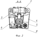
- на фиг.2 изображен поперечный разрез А-А по цилиндрам зажима;- figure 2 shows a transverse section aa along the clamping cylinders;
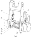
- на фиг.3 изображена конструкция электрических контактов-хомутов с управляемыми приводами.- figure 3 shows the design of the electrical contacts-clamps with controlled drives.
Машина для контактной стыковой сварки рельсов содержащая в себе два клещевых зажимных устройства 1 и 2 (фиг.1), каждый из которых состоит из двух двуплечих рычагов 3 и 4 (фиг.2), насаженных на общую центральную ось 5 (фиг.1) с возможностью относительного перемещения по ней от гидроцилиндров перемещения и осадки 6 (фиг.2), которые работают синхронно от общей гидравлической магистрали. Клещевые зажимы 1 и 2 изолированы друг от друга по всем трем соединяющим их штокам; а каждый из двуплечих рычагов 3 и 4, в верхней части шарнирно связанный со штоком или корпусом гидроцилиндров зажатия 7 (фиг.2), а в нижней части имеет токоподводящие зажимные губки 8 (фиг.2), которые зажимают свариваемые рельсы за шейку и изготовленные согласно профилю шейки свариваемых рельсов. В рычагах правого зажима размещены два сварочные трансформатора 9 (фиг.2), которые соединенные параллельно. Сварочный ток к зажимным губкам правого зажима подводится жесткими перемычками непосредственно от сварочных трансформаторов. К зажимным губкам левого зажима ток подводится через штоки 10 (фиг.1) цилиндров перемещения и осадки, электрические контакты-хомуты 11 (фиг.1) с управляемым приводом 13 (фиг.3) и гибкие токоподводящие перемычки 12 (фиг.1). Электрические контакты-хомуты с управляемым приводом 13, включают в себя верхнюю 14 (фиг.3) и нижнюю 15 (фиг.3) шарнирно соединенные между собой части, которые зажимаются-разжимаются на штоке цилиндров перемещения и осадки с помощью винта 16 (фиг.3) и гайки 17 (фиг.3). Верхняя часть электрического контакта-хомута имеет отверстия, через которые проходят направляющие стержни 18 (фиг.3), между боковой поверхностью электрического контакта-хомута и боковой стенкой зажимного рычага 19 (фиг.3) установлена фиксирующая пружина 20 (фиг.3). С помощью гибкой токоподводящей перемычки 12, электрический контакт-хомут 11 с управляемым приводом 13 связан с токоподводящими зажимными губками 8.A machine for flash butt welding of rails comprising two clamping devices 1 and 2 (Fig. 1), each of which consists of two two-
Работу рельсосварочной машины с электрическими контактами-хомутами с управляемыми приводами можно описать следующим образом. При сварке длинномерных рельсовых секций, которые нужно предварительно подтянуть с необходимым усилием на заданную величину, их концы с помощью цилиндров зажатия 7 зажимаются двуплечими рычагами 3 и 4 в клещевых зажимах 1 и 2. При этом клещевые зажимы 1 и 2 разведены в крайнее правое положение, электрический контакт-хомут 11 с управляемым приводом 13 разжат и зафиксирован в строго определенном месте, а между электрическим контактом-хомутом 11 и штоком 10 цилиндров перемещения и осадки есть фиксированный зазор, который разрешает штоку свободно перемещаться, а электрическому контакту-хомуту остаться неподвижным. При прохождении клещевыми зажимами расстояния необходимого для подтягивания длинномерных рельсовых секций дается команда на управляемый привод 13 электрического контакта-хомута. Электрические контакты-хомуты 11 с необходимым усилием зажимаются на штоках перемещения и осадки 10 и сварочный ток с помощью гибких токоподводящих перемычек 12 подается к зажимным токоподводящим губкам 8. По окончанию процесса сварки длинномерных рельсовых секций дается команда на разжатие электрического контакта-хомута 11, и с помощью фиксирующей пружины 19, при разведении машины в исходное положение, электрический контакт-хомут 11 возвращается на свое строго определенное место. Машина готовая для выполнения следующего цикла сварки.The operation of a rail welding machine with electrical contacts-clamps with controlled drives can be described as follows. When welding long rail sections that need to be pre-tightened with the required force by a predetermined amount, their ends are clamped by
Использование машины для контактной стыковой сварки рельсов с электрическими контактами-хомутами с управляемыми приводами позволяет использовать ограниченную длину токоподводящих перемычек и таким образом, избежать увеличения сопротивления электрического контура сварочной машины, а значит иметь стабильный процесс сварки и, как следствие, предотвратить появление бракованных сварных соединений.The use of a flash butt welding machine for rails with electric contacts-clamps with controlled drives allows you to use a limited length of current-carrying jumpers and thus avoid increasing the resistance of the electric circuit of the welding machine, and therefore have a stable welding process and, as a result, prevent the appearance of defective welded joints.
Claims (1)
Applications Claiming Priority (2)
| Application Number | Priority Date | Filing Date | Title |
|---|---|---|---|
| UAA201108577 | 2011-07-08 | ||
| UAA201108577A UA101539C2 (en) | 2011-07-08 | 2011-07-08 | Machine for contact upset welding rails |
Publications (2)
| Publication Number | Publication Date |
|---|---|
| RU2011143203A RU2011143203A (en) | 2013-04-27 |
| RU2503525C2 true RU2503525C2 (en) | 2014-01-10 |
Family
ID=45930141
Family Applications (1)
| Application Number | Title | Priority Date | Filing Date |
|---|---|---|---|
| RU2011143203/02A RU2503525C2 (en) | 2011-07-08 | 2011-10-25 | Machine for rail contact butt welding |
Country Status (4)
| Country | Link |
|---|---|
| US (1) | US8907242B2 (en) |
| GB (1) | GB2492611A (en) |
| RU (1) | RU2503525C2 (en) |
| UA (1) | UA101539C2 (en) |
Cited By (1)
| Publication number | Priority date | Publication date | Assignee | Title |
|---|---|---|---|---|
| RU2748185C1 (en) * | 2020-07-15 | 2021-05-20 | Общество с ограниченной ответственностью Современные сварочные технологии | Suspended rail butt welding machine |
Families Citing this family (4)
| Publication number | Priority date | Publication date | Assignee | Title |
|---|---|---|---|---|
| CN103388291B (en) * | 2013-07-24 | 2015-04-22 | 常州市瑞泰工程机械有限公司 | Channel steel rail flash welding machine |
| AT515525B1 (en) * | 2014-07-28 | 2015-10-15 | Plasser & Theurer Export Von Bahnbaumaschinen Gmbh | welding unit |
| UA116022C2 (en) * | 2015-12-15 | 2018-01-25 | Інститут Електрозварювання Ім. Є.О. Патона Нан України | CONTACT STICK WELDING MACHINE |
| AT15368U1 (en) * | 2016-04-01 | 2017-07-15 | Plasser & Theurer Export Von Bahnbaumaschinen Gmbh | Welding unit for welding two rails of a track |
Citations (8)
| Publication number | Priority date | Publication date | Assignee | Title |
|---|---|---|---|---|
| JPS56136292A (en) * | 1980-03-27 | 1981-10-24 | Nippon Kokan Kk <Nkk> | Rail clamping device to be used when rails are pressure welded |
| UA9911A (en) * | 1991-03-13 | 1996-09-30 | Ігор Васильович Гуляєв | Machine for contact butt welding |
| US6163003A (en) * | 1998-06-12 | 2000-12-19 | Chemetron-Railway Products, Inc. | Method and apparatus for controlling forging force during flash butt welding of railway rails |
| US6294752B1 (en) * | 1999-12-16 | 2001-09-25 | Sergei I. Kuchuk-Yatsenko | Method of flash-butt welding |
| UA56986C2 (en) * | 1996-08-05 | 2003-06-16 | Інститут електрозварювання ім.Є.О.Патона НАН України | Machine for contact jump welding of rails |
| EP0868250B1 (en) * | 1995-12-05 | 2003-09-17 | Esab AB | Welding device |
| RU71924U1 (en) * | 2007-12-25 | 2008-03-27 | Байдин Игорь Владимирович | RAILWAY CONTACT BUTT MACHINE |
| RU2007146001A (en) * | 2007-12-13 | 2009-06-20 | Владимир Иванович Дедюх (UA) | RADIATOR Fusion Butt Welding Machine |
Family Cites Families (14)
| Publication number | Priority date | Publication date | Assignee | Title |
|---|---|---|---|---|
| US1986740A (en) * | 1933-12-29 | 1935-01-01 | American Steel & Wire Co | Welding machine |
| US3349216A (en) * | 1964-06-04 | 1967-10-24 | Inst Elektroswarki Patona | Machine for resistance butt-welding |
| US4217478A (en) * | 1975-10-08 | 1980-08-12 | Golomvzjuk Ivan K | Device for controlling butt welding machine |
| US4414454A (en) * | 1981-08-13 | 1983-11-08 | H. A. Schlatter Ag | Method of welding continuous rails and apparatus therefor |
| EP0119098A3 (en) * | 1983-03-14 | 1984-10-24 | A.I. Welders Limited | A method and apparatus for aligning two work pieces |
| US4716836A (en) * | 1986-07-14 | 1988-01-05 | H. A. Schlatter Ag | Suspended rail welder |
| EP0597215B1 (en) * | 1992-11-09 | 1996-11-27 | H.A. Schlatter Ag | Flash butt welding maschine |
| JP3339356B2 (en) * | 1997-04-16 | 2002-10-28 | 日本鋼管株式会社 | Flash butt welding equipment |
| US6396020B1 (en) * | 1997-12-16 | 2002-05-28 | Holland Company | Rail welding apparatus incorporating rail restraining device, weld containment device and weld delivery unit |
| US6109503A (en) * | 1998-05-15 | 2000-08-29 | Sabre International, Inc. | Internal pipe clamp |
| US6886470B2 (en) * | 2000-08-18 | 2005-05-03 | Holland Corporation | Rail welderhead shear apparatus |
| AT5203U3 (en) * | 2002-01-28 | 2003-01-27 | Plasser Bahnbaumasch Franz | WELDING UNIT |
| US6756558B2 (en) * | 2002-05-31 | 2004-06-29 | Centaur, Inc. | High current, low impedance resistance welding device |
| AT6941U3 (en) * | 2004-02-23 | 2005-03-25 | Plasser Bahnbaumasch Franz | WELDING UNIT FOR WELDING TWO RAILS OF A TRACK AND METHOD |
-
2011
- 2011-07-08 UA UAA201108577A patent/UA101539C2/en unknown
- 2011-10-25 RU RU2011143203/02A patent/RU2503525C2/en not_active IP Right Cessation
- 2011-12-29 US US13/339,921 patent/US8907242B2/en not_active Expired - Fee Related
-
2012
- 2012-02-15 GB GB1202600.1A patent/GB2492611A/en not_active Withdrawn
Patent Citations (8)
| Publication number | Priority date | Publication date | Assignee | Title |
|---|---|---|---|---|
| JPS56136292A (en) * | 1980-03-27 | 1981-10-24 | Nippon Kokan Kk <Nkk> | Rail clamping device to be used when rails are pressure welded |
| UA9911A (en) * | 1991-03-13 | 1996-09-30 | Ігор Васильович Гуляєв | Machine for contact butt welding |
| EP0868250B1 (en) * | 1995-12-05 | 2003-09-17 | Esab AB | Welding device |
| UA56986C2 (en) * | 1996-08-05 | 2003-06-16 | Інститут електрозварювання ім.Є.О.Патона НАН України | Machine for contact jump welding of rails |
| US6163003A (en) * | 1998-06-12 | 2000-12-19 | Chemetron-Railway Products, Inc. | Method and apparatus for controlling forging force during flash butt welding of railway rails |
| US6294752B1 (en) * | 1999-12-16 | 2001-09-25 | Sergei I. Kuchuk-Yatsenko | Method of flash-butt welding |
| RU2007146001A (en) * | 2007-12-13 | 2009-06-20 | Владимир Иванович Дедюх (UA) | RADIATOR Fusion Butt Welding Machine |
| RU71924U1 (en) * | 2007-12-25 | 2008-03-27 | Байдин Игорь Владимирович | RAILWAY CONTACT BUTT MACHINE |
Cited By (1)
| Publication number | Priority date | Publication date | Assignee | Title |
|---|---|---|---|---|
| RU2748185C1 (en) * | 2020-07-15 | 2021-05-20 | Общество с ограниченной ответственностью Современные сварочные технологии | Suspended rail butt welding machine |
Also Published As
| Publication number | Publication date |
|---|---|
| GB201202600D0 (en) | 2012-03-28 |
| RU2011143203A (en) | 2013-04-27 |
| CN102861978A (en) | 2013-01-09 |
| UA101539C2 (en) | 2013-04-10 |
| US8907242B2 (en) | 2014-12-09 |
| US20130008874A1 (en) | 2013-01-10 |
| GB2492611A (en) | 2013-01-09 |
Similar Documents
| Publication | Publication Date | Title |
|---|---|---|
| RU2503525C2 (en) | Machine for rail contact butt welding | |
| JP5560500B2 (en) | Welding head for rail welding | |
| KR20150087786A (en) | Method for hot line work of power distribution equipment | |
| KR101397186B1 (en) | Weaving type welding apparatus for welding pipe | |
| CN104589019A (en) | Pipe penetrating machine for penetrating core pipe into heat insulation pipe | |
| WO2010137196A1 (en) | Terminal inserting device | |
| CN106253154B (en) | A kind of electric power cable skin cutter device | |
| CN108555192B (en) | A wire mesh welding machine | |
| JP5687981B2 (en) | Filament winding equipment | |
| CN108044087A (en) | A kind of ingot stripper | |
| EP2677046A1 (en) | Furnace and method for electroslag refining | |
| DE2833695C2 (en) | Electroslag remelting plant with coaxial current paths | |
| CN103510739A (en) | Multifunctional combinatorial insulation cross arm | |
| CN210281059U (en) | High-frequency welding equipment for wiring of motor stator winding | |
| CN207710114U (en) | Welding mechanism of a draw wire butt welding machine | |
| WO2010012011A1 (en) | Method and device for forming the welding wire end | |
| CN206286732U (en) | Welder | |
| KR101506112B1 (en) | Adjustment equipment of welding torch height | |
| CN210997011U (en) | Composite stirrup welding machine structure | |
| CN201471070U (en) | Strong hot pressure copper rod welding machine | |
| CN106513970A (en) | Welding device | |
| CN102861978B (en) | Machine for the flash butt welding of track | |
| CN203531492U (en) | Multifunctional combined insulating cross arm | |
| CN111774683B (en) | Full-automatic wire dip welding machine | |
| CN106216573B (en) | Wire horizontal feeding system |
Legal Events
| Date | Code | Title | Description |
|---|---|---|---|
| MM4A | The patent is invalid due to non-payment of fees |
Effective date: 20151026 |