RU2500602C2 - Machine for making hygroscopic products - Google Patents
Machine for making hygroscopic products Download PDFInfo
- Publication number
- RU2500602C2 RU2500602C2 RU2010152433/13A RU2010152433A RU2500602C2 RU 2500602 C2 RU2500602 C2 RU 2500602C2 RU 2010152433/13 A RU2010152433/13 A RU 2010152433/13A RU 2010152433 A RU2010152433 A RU 2010152433A RU 2500602 C2 RU2500602 C2 RU 2500602C2
- Authority
- RU
- Russia
- Prior art keywords
- elements
- group
- pieces
- roller
- fastening
- Prior art date
Links
Images


Classifications
-
- B—PERFORMING OPERATIONS; TRANSPORTING
- B65—CONVEYING; PACKING; STORING; HANDLING THIN OR FILAMENTARY MATERIAL
- B65H—HANDLING THIN OR FILAMENTARY MATERIAL, e.g. SHEETS, WEBS, CABLES
- B65H39/00—Associating, collating, or gathering articles or webs
- B65H39/14—Associating sheets with webs
-
- A—HUMAN NECESSITIES
- A61—MEDICAL OR VETERINARY SCIENCE; HYGIENE
- A61F—FILTERS IMPLANTABLE INTO BLOOD VESSELS; PROSTHESES; DEVICES PROVIDING PATENCY TO, OR PREVENTING COLLAPSING OF, TUBULAR STRUCTURES OF THE BODY, e.g. STENTS; ORTHOPAEDIC, NURSING OR CONTRACEPTIVE DEVICES; FOMENTATION; TREATMENT OR PROTECTION OF EYES OR EARS; BANDAGES, DRESSINGS OR ABSORBENT PADS; FIRST-AID KITS
- A61F13/00—Bandages or dressings; Absorbent pads
- A61F13/15—Absorbent pads, e.g. sanitary towels, swabs or tampons for external or internal application to the body; Supporting or fastening means therefor; Tampon applicators
- A61F13/15577—Apparatus or processes for manufacturing
- A61F13/15756—Applying tabs, strips, tapes, loops; Knotting the ends of pads
-
- A—HUMAN NECESSITIES
- A61—MEDICAL OR VETERINARY SCIENCE; HYGIENE
- A61F—FILTERS IMPLANTABLE INTO BLOOD VESSELS; PROSTHESES; DEVICES PROVIDING PATENCY TO, OR PREVENTING COLLAPSING OF, TUBULAR STRUCTURES OF THE BODY, e.g. STENTS; ORTHOPAEDIC, NURSING OR CONTRACEPTIVE DEVICES; FOMENTATION; TREATMENT OR PROTECTION OF EYES OR EARS; BANDAGES, DRESSINGS OR ABSORBENT PADS; FIRST-AID KITS
- A61F13/00—Bandages or dressings; Absorbent pads
- A61F13/15—Absorbent pads, e.g. sanitary towels, swabs or tampons for external or internal application to the body; Supporting or fastening means therefor; Tampon applicators
- A61F13/15577—Apparatus or processes for manufacturing
- A61F13/15764—Transferring, feeding or handling devices; Drives
-
- B—PERFORMING OPERATIONS; TRANSPORTING
- B65—CONVEYING; PACKING; STORING; HANDLING THIN OR FILAMENTARY MATERIAL
- B65H—HANDLING THIN OR FILAMENTARY MATERIAL, e.g. SHEETS, WEBS, CABLES
- B65H35/00—Delivering articles from cutting or line-perforating machines; Article or web delivery apparatus incorporating cutting or line-perforating devices, e.g. adhesive tape dispensers
- B65H35/04—Delivering articles from cutting or line-perforating machines; Article or web delivery apparatus incorporating cutting or line-perforating devices, e.g. adhesive tape dispensers from or with transverse cutters or perforators
-
- B—PERFORMING OPERATIONS; TRANSPORTING
- B65—CONVEYING; PACKING; STORING; HANDLING THIN OR FILAMENTARY MATERIAL
- B65H—HANDLING THIN OR FILAMENTARY MATERIAL, e.g. SHEETS, WEBS, CABLES
- B65H2301/00—Handling processes for sheets or webs
- B65H2301/30—Orientation, displacement, position of the handled material
- B65H2301/36—Positioning; Changing position
- B65H2301/361—Positioning; Changing position during displacement
- B65H2301/3613—Lateral positioning
-
- B—PERFORMING OPERATIONS; TRANSPORTING
- B65—CONVEYING; PACKING; STORING; HANDLING THIN OR FILAMENTARY MATERIAL
- B65H—HANDLING THIN OR FILAMENTARY MATERIAL, e.g. SHEETS, WEBS, CABLES
- B65H2301/00—Handling processes for sheets or webs
- B65H2301/40—Type of handling process
- B65H2301/44—Moving, forwarding, guiding material
- B65H2301/445—Moving, forwarding, guiding material stream of articles separated from each other
- B65H2301/4455—Diverting a main stream into part streams
- B65H2301/44552—Diverting a main stream into part streams by alternatively directing articles following each other to appropriate part stream
-
- B—PERFORMING OPERATIONS; TRANSPORTING
- B65—CONVEYING; PACKING; STORING; HANDLING THIN OR FILAMENTARY MATERIAL
- B65H—HANDLING THIN OR FILAMENTARY MATERIAL, e.g. SHEETS, WEBS, CABLES
- B65H2406/00—Means using fluid
- B65H2406/30—Suction means
- B65H2406/34—Suction grippers
- B65H2406/345—Rotary suction grippers
- B65H2406/3452—Rotary suction grippers performing reciprocating movement during rotation
- B65H2406/34525—Rotary suction grippers performing reciprocating movement during rotation parallely to the axis of rotation
-
- B—PERFORMING OPERATIONS; TRANSPORTING
- B65—CONVEYING; PACKING; STORING; HANDLING THIN OR FILAMENTARY MATERIAL
- B65H—HANDLING THIN OR FILAMENTARY MATERIAL, e.g. SHEETS, WEBS, CABLES
- B65H2801/00—Application field
- B65H2801/57—Diaper manufacture
Abstract
Description
ОБЛАСТЬ ТЕХНИКИFIELD OF TECHNOLOGY
Настоящее изобретение относится к машине для изготовления гигроскопических изделий.The present invention relates to a machine for manufacturing hygroscopic products.
В частности, изобретение используется при изготовлении одноразовых пеленок для младенцев или гигиенических прокладок для взрослых, страдающих недержанием. Данное описание относится непосредственно к этим изделиям.In particular, the invention is used in the manufacture of disposable diapers for infants or sanitary pads for adults with incontinence. This description applies directly to these products.
УРОВЕНЬ ТЕХНИКИBACKGROUND
Как известно, пеленки или гигиенические прокладки для людей, страдающих недержанием, содержат гигроскопическую прокладку, обычно изготовленную из целлюлозных волокон, помещенных в мягкий наружный элемент, и имеющую с одной стороны проницаемый слой из нетканой ткани, а с другой стороны непроницаемый слой из полиэтилена. Эти два слоя соединены друг с другом по соответствующим краям, имеющим определенную форму и снабженным эластичными удерживающими элементами.As you know, diapers or sanitary pads for people with incontinence contain a hygroscopic pad, usually made of cellulose fibers, placed in a soft outer element, and having on one side a permeable layer of non-woven fabric, and on the other hand an impermeable layer of polyethylene. These two layers are connected to each other at respective edges having a certain shape and provided with elastic holding elements.
В известных машинах пеленки или гигиенические прокладки изготавливаются путем разрезания на куски непрерывной полосы пеленок или гигиенических прокладок, примыкающих друг к другу и соединенных между собой.In known machines, diapers or sanitary napkins are made by cutting into pieces a continuous strip of diapers or sanitary napkins adjacent to each other and interconnected.
Пеленки или гигиенические прокладки содержат, по отношению к своей продольной оси, переднюю часть и заднюю часть, на которой обычно закреплены два крепежных и застегивающих элемента, служащих для правильного и надежного закрепления такого изделия на бедрах пользователя.Diapers or sanitary napkins contain, in relation to their longitudinal axis, a front part and a back part, on which two fastening and fastening elements are usually fixed, which serve to correctly and reliably fix such a product on the user's hips.
Крепежные и застегивающие элементы обычно подаются парами и накладываются на непрерывную полосу пеленок или гигиенических прокладок до ее разрезания на отдельные пеленки или прокладки.Fasteners and fasteners are usually served in pairs and applied to a continuous strip of diapers or sanitary napkins until it is cut into separate diapers or napkins.
В патентной заявке BO 2007А000431 данного заявителя описана машина для изготовления гигроскопических изделий такого типа.Patent application BO 2007A000431 of this applicant describes a machine for manufacturing hygroscopic products of this type.
Эта машина содержит транспортер для подачи непрерывной полосы гигроскопических изделий через позицию подачи крепежных и застегивающих элементов к устройству резки этой полосы на отдельные гигроскопические изделия.This machine contains a conveyor for feeding a continuous strip of absorbent products through the feed position of the fastening and fastening elements to a device for cutting this strip into individual absorbent products.
Эти элементы располагаются парами и накладываются на полосу с помощью блока, в который подается непрерывная лента из высокоэластичного материала.These elements are arranged in pairs and are superimposed onto the strip using a block into which a continuous tape of highly elastic material is fed.
Этот блок содержит режущий элемент, содержащий два ролика, вращающихся в противоположных направлениях и расположенных по существу касательно друг к другу. Ролики служат для получения из непрерывной ленты последовательности кусков, образующих трапециевидные крепежные элементы, посредством последовательных резов наискось в противоположных направлениях вдоль продольной оси ленты, с чередованием направления резки.This block contains a cutting element containing two rollers rotating in opposite directions and located essentially tangent to each other. The rollers are used to obtain from a continuous tape a sequence of pieces forming trapezoidal fasteners, through successive cuts obliquely in opposite directions along the longitudinal axis of the tape, with alternating cutting directions.
После этой операции из ленты образуется непрерывная последовательность кусков, которые имеют трапециевидную форму и поочередно повернуты своими основаниями на 180° относительно друг друга.After this operation, a continuous sequence of pieces is formed from the tape, which have a trapezoidal shape and are alternately rotated by their bases 180 ° relative to each other.
За режущим элементом, по ходу процесса изготовления, расположен разделительный ролик, отводящий куски на некоторое расстояние друг от друга. Для этого разделительный ролик, установленный по существу касательно к ролику указанной пары роликов режущего элемента, имеет призматическую форму, а каждая из его граней, расположенная под углом к смежным граням, снабжена всасывающим гнездом по существу прямоугольной формы для приема и удерживания одного из кусков.Behind the cutting element, during the manufacturing process, there is a separation roller, which takes the pieces to a certain distance from each other. For this, the separation roller, which is installed essentially with respect to the roller of the indicated pair of rollers of the cutting element, has a prismatic shape, and each of its faces, located at an angle to adjacent faces, is provided with a suction socket of a substantially rectangular shape for receiving and holding one of the pieces.
При вращении разделительного ролика каждое всасывающее гнездо может также перемещаться возвратно-поступательно параллельно оси разделяющего ролика и в противоположном направлении относительно смежных гнезд между позицией приема куска и второй позицией, в которой это гнездо расположено касательно к ролику, служащему для образования пар крепежных элементов.When the separation roller is rotated, each suction socket can also move reciprocally parallel to the axis of the separation roller and in the opposite direction with respect to adjacent sockets between the receiving position of the piece and the second position in which this socket is located tangentially to the roller serving to form pairs of fasteners.
Во время перемещения между входом и выходом разделительного ролика крепежные элементы из положения, в котором они расположены в один ряд, перестраиваются в положение, в котором они расположены в два смещенные друг относительно друга ряда так, что большие основания трапециевидных кусков одного ряда находятся напротив больших оснований кусков другого ряда.During the movement between the input and output of the separation roller, the fasteners from the position in which they are located in one row are rebuilt in the position in which they are located in two rows offset from each other so that the large bases of the trapezoidal pieces of one row are opposite the large bases pieces of another row.
Подающий блок содержит также указанный выше ролик для образования пар крепежных элементов, который устанавливает на одной линии, поперечной направлению их подачи, каждый крепежный элемент одного ряда со смежным крепежным элементом второго ряда.The feed unit also contains the aforementioned roller for forming pairs of fasteners, which sets in one line transverse to the direction of their supply, each fastener of the same row with an adjacent fastener of the second row.
С этой целью ролик, образующий пары, содержит два соосных барабана, каждый из которых имеет множество радиальных рычагов, отделенных друг от друга равными угловыми расстояниями для использования соответствующих всасывающих гнезд для захвата крепежных элементов с разделяющего ролика. Во время переноса от позиции захвата с разделяющего ролика на линию подачи непрерывной полосы два радиальных рычага, относящиеся к двум последовательным кускам каждого из двух рядов, перемещаются друг относительно друга, создавая пару элементов, расположенных на одной линии, поперечной направлению подачи.To this end, the pair-forming roller comprises two coaxial drums, each of which has a plurality of radial arms separated from each other by equal angular distances to use the respective suction sockets for gripping fasteners from the separating roller. During the transfer from the capture position from the separating roller to the feed line of the continuous strip, two radial arms belonging to two consecutive pieces of each of the two rows move relative to each other, creating a pair of elements located on the same line transverse to the feed direction.
Затем трапециевидные элементы накладываются парами на непрерывную полосу гигроскопических изделий согласно заданному шагу и прикрепляются к ней более длинными основаниями.Then the trapezoidal elements are superimposed in pairs on a continuous strip of absorbent products according to a given step and attached to it with longer bases.
Однако описанный выше блок подачи крепежных элементов ограничивает рабочую скорость машины, в которой он установлен.However, the fastener supply unit described above limits the operating speed of the machine in which it is installed.
Во-первых, это обусловлено крайне сложной механической конструкцией ролика для образования пар крепежных элементов.Firstly, this is due to the extremely complex mechanical construction of the roller to form pairs of fasteners.
Во-вторых, во время относительного скользящего перемещения гнезд разделительного ролика поперек к направлению их подачи, особенно при высоких рабочих скоростях, края трапециевидных кусков могут задевать друг за друга несмотря на призматическую форму этого ролика, что может приводить к их отделению от соответствующих опор.Secondly, during the relative sliding movement of the nests of the separation roller across to the direction of their feed, especially at high operating speeds, the edges of the trapezoidal pieces can touch one another despite the prismatic shape of this roller, which can lead to their separation from the corresponding supports.
РАСКРЫТИЕ ИЗОБРЕТЕНИЯSUMMARY OF THE INVENTION
Целью настоящего изобретения является создание способа и машины для изготовления гигроскопических изделий, в которых устранены указанные выше недостатки, присущие уровню техники.The aim of the present invention is to provide a method and machine for the manufacture of absorbent products, which eliminated the above disadvantages inherent in the prior art.
Способ и машина для изготовления гигроскопических изделий согласно изобретению описаны в одном или нескольких пунктах формулы изобретения.A method and machine for manufacturing hygroscopic products according to the invention are described in one or more claims.
КРАТКОЕ ОПИСАНИЕ ЧЕРТЕЖЕЙBRIEF DESCRIPTION OF THE DRAWINGS
Далее изобретение описано со ссылками на чертежи, на которых представлен предпочтительный вариант его осуществления, не ограничивающий объема изобретения.The invention is further described with reference to the drawings, in which a preferred embodiment is presented, not limiting the scope of the invention.
фиг.1 схематично изображает в аксонометрии машину для изготовления гигроскопических изделий согласно изобретению,figure 1 schematically depicts a perspective view of a machine for the manufacture of absorbent products according to the invention,
фиг.2 изображает в плане гигроскопическое изделие, изготовленное на машине, показанной на фиг.1;figure 2 depicts in plan a hygroscopic product made on the machine shown in figure 1;
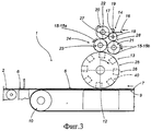
фиг.3 схематично изображает спереди фрагмент фиг.1;figure 3 schematically depicts a front fragment of figure 1;
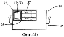
фиг.4a, 4b, 4c, 4d, 4e схематично изображают операции, выполняемые машиной, показанной на фиг.1.figa, 4b, 4c, 4d, 4e schematically depict the operations performed by the machine shown in figure 1.
ПОДРОБНОЕ ОПИСАНИЕ ПРЕДПОЧТИТЕЛЬНЫХ ВАРИАНТОВ ОСУЩЕСТВЛЕНИЯ ИЗОБРЕТЕНИЯDETAILED DESCRIPTION OF THE PREFERRED EMBODIMENTS
На фиг.1 и 2 показана машина 1 для изготовления гигроскопических изделий 2, в частности одноразовых пеленок или гигиенических прокладок по существу прямоугольной формы, имеющих, в направлении продольной оси A, первую или переднюю часть 3 и вторую или заднюю часть 4, разделенные друг от друга центральной частью 5, расположенной между искривленными внутрь участками двух продольных сторон изделия 2.Figures 1 and 2 show a
Изделия 2 содержат внутреннюю гигроскопическую прокладку, как правило из целлюлозных волокон, помещенных в мягкий наружный элемент, имеющую с одной стороны проницаемый слой из нетканой ткани, а с другой стороны - непроницаемый слой из полиэтилена.
Каждое изделие 2 снабжено по линии талии двумя крепежными и застегивающими элементами 6 или язычками, отходящими от боковых сторон тела изделия 2. Более конкретно, элементы 6 отходят от задней части 4 изделия 2 и при его использовании служат для наложения на соответствующие боковые участки передней части 3 с целью закрепления изделия 2 вокруг бедер пользователя.Each
Элементы 6 обычно представляют собой куски в виде полосы предпочтительно из эластичного материала, имеющие поверхность, частично покрытую клейким веществом или снабженную другими средствами быстрого крепления.
Машина 1 содержит линию 8 подачи непрерывной полосы 7 расположенных друг за другом изделий 2 в заданном направлении L.
Линия 8 подачи проходит горизонтально по транспортеру 9, содержащему ленту, охватывающую концевые ролики 10 (показан только один из них), до позиции резки, где режущий элемент 11 разрезает непрерывную полосу 7 на отдельные изделия 2.The
У транспортера 9, до режущего элемента 11, находится позиция 12 подачи крепежных элементов 6 с помощью блока 13, содержащего несколько вращающихся транспортеров, состоящих из роликов, горизонтальные оси которых параллельны направлению T, поперечному направлению L.At the
Как показано на фиг.3, блок 13 содержит на своем верхнем конце устройство 14 для резки непрерывной ленты 16 из высокоэластичного материала, сматываемой с катушки (не показана), на куски 15, предназначенные для образования крепежных элементов 6.As shown in FIG. 3,
Устройство 14 резки содержит два ролика, вращающихся в противоположных направлениях и взаимодействующих друг с другом. Более конкретно, оно содержит верхний режущий ролик 17, вращающийся по часовой стрелке, и нижний ролик 18, вращающийся против часовой стрелки и предназначенный для транспортировки кусков 15.The
Ролик 17 имеет два диаметрально противоположных ножа 19, расположенных, относительно оси ролика, с наклоном в противоположных направлениях.The
Транспортировочный ролик 18 имеет цилиндрическую поверхность с отверстиями, соединенными со всасывающим устройством, для удерживания кусков 15 после их отрезания от ленты 16.The
Выше и ниже транспортировочного ролика 18 относительно направления его вращения расположены два ролика 20 и 21, которые установлены по существу касательно к ролику 18 и вращаются по часовой стрелке. Эти ролики 20, 21 образуют разделительное устройство 22, предназначенное для получения соответствующих последовательностей крепежных элементов 6.Above and below the
Ролики 20 и 21 установлены по существу касательно к ролику 23, вращающемуся против часовой стрелки и образующему устройство 24 для получения пар кусков 15.The
Ролик 25, вращающийся по часовой стрелке, установлен по существу касательно к ролику 23 и транспортеру 9 и образует ускорительное устройство 26.A clockwise rotating
На фиг.4a, 4b, 4c, 4d, 4e показано, что лента 16, проходя между роликом 17, снабженным установленными наклонно ножами 19, и роликом 18, разрезается на куски 15 трапециевидной формы, которые удерживаются на цилиндрической поверхности ролика 18 путем присасывания и расположены так, что куски, ориентированные в одном направлении, чередуются с кусками, ориентированными в противоположном направлении.On figa, 4b, 4c, 4d, 4e it is shown that the
Для большей ясности, куски, обращенные большим основанием вправо, обозначены цифровой позицией 15a, а куски, обращенные большим основанием влево, - цифровой позицией 15b.For clarity, the pieces facing the big base to the right are indicated by the numeral 15a, and the pieces facing the large base to the left are the numeral 15b.
Ролик 20 и ролик 21, установленные касательно к ролику 18 в двух позициях переноса, 27 и 28 соответственно, по существу одинаковы и вращаются по часовой стрелке. На цилиндрических поверхностях этих роликов 20, 21 имеется множество гнезд 29 и 30, разделенных равными угловыми промежутками в соответствии с заданным шагом P.The
Каждое гнездо 29, 30, служащее для приема и удержания одного из трапециевидных кусков 15 путем его присасывания, содержит блок 31, который может скользить между двумя крайними положениями в направлении, параллельном осям роликов, под управлением приводных средств (не показаны).Each
Более конкретно, блоки 31, относящиеся к ролику 20, захватывают куски 15a, обращенные большим основанием вправо, в позиции 27, а блоки 31, относящиеся к ролику 21, захватывают куски 15b, обращенные большим основанием влево, в позиции 28.More specifically, the
Начиная от соответствующих позиций 27 и 28 переноса, блоки 31 при вращении роликов 20 и 21 скользят в противоположных друг другу направлениях, образуя соответствующие последовательности 32 и 33, каждая из которых содержит куски с одинаковой ориентацией и которые разнесены друг от друга параллельно осям роликов на расстояние, меньшее поперечного размера полосы 7.Starting from the
Ролик 23, образующий пары кусков и вращающийся против часовой стрелки, имеет на наружной цилиндрической поверхности вблизи каждого из двух продольных концов кольцо из гнезд 34 и 35, отделенных друг от дуга равными угловыми расстояниями в соответствии с шагом P и расположенных так, что каждое гнездо 34 расположено в осевом направлении по одной линии с соответствующим гнездом 35, образуя пару 36.The
При вращении ролика 23 он захватывает, соответственно положению каждой пары 36 гнезд 34 и 35, сначала кусок 15a с ролика 20 и затем кусок 15b с ролика 21, образуя пару кусков 15, разделенных указанным выше расстоянием, которое меньше поперечного размера ленты 7.When the
После прохождения позиции, где ролик 23 и ролик 21 расположены касательно друг к другу, пара кусков 15 переносится из пары 36 гнезд 34, 35 в соответствующую пару 37 всасывающих гнезд 38, 39 на ускорительном ролике 25.After passing the position where the
Каждая пара 37 гнезд 38, 39 установлена на радиальном стержне 40, который при вращении ролика 25 может совершать колебательные движения на оси, параллельной направлению Т, под управлением кулачкового приводного средства (не показано) известного типа, описанного в указанной выше патентной заявке BO 2007А000431.Each
Следовательно, в позиции захвата пары кусков 15 соответствующие всасывающие гнезда 38, 39 ролика 25 имеют такую же касательную скорость, что и ролик 23, а в момент переноса кусков 15 касательная скорость пары 37 всасывающих гнезд совпадает со скоростью подачи полосы 7, с соответствующим изменением шага пары кусков 15 от значения P на значение P1, которое совпадает с шагом отрезков полосы 7, предназначенных для образования отдельных пеленок или гигиенических прокладок.Therefore, in the capture position of the pair of
В позиции, в которой ролик 25 и транспортер 9 расположены касательно друг к другу, крепежные элементы 6 накладываются на каждый из отрезков полосы 7.In the position in which the
Иными словами, описанная выше машина 1 позволяет изготавливать изделия 2 в соответствии со способом, согласно которому крепежные и застегивающие элементы получают путем безотходной резки непрерывной ленты 16 для получения из нее первой и второй групп крепежных и застегивающих элементов, причем элементы первой группы чередуются с элементами второй группы и ориентированы по сравнению с ними в противоположном направлении. Затем разрезанная лента 16 проходит через позицию 27, где захватываются элементы первой группы, и через позицию 28, где захватываются элементы второй группы. Элементы первой группы подаются роликом 20 от позиции 27 по первой траектории, а элементы второй группы подаются роликом 21 от позиции 28 по другой, второй траектории. При движении по первой траектории элементы первой группы перемещаются вбок в первом направлении. Одновременно с этим, при движении по второй траектории элементы второй группы перемещаются вбок во втором направлении, противоположном первому направлению. Оба эти перемещения происходят параллельно осям роликов 20 и 21.In other words, the
Затем элементы первой группы и элементы второй группы переносят по отдельности с роликов 20 и 21 на ролик 23, образующий общую, третью траекторию подачи крепежных элементов. На ролике 23 рядом с каждым элементом первой группы на ролике 23 синхронизированным образом размещают соответствующий элемент второй группы на расстоянии от элемента первой группы и с ориентацией в направлении, противоположном направлению ориентации элемента первой группы. После размещения элементов на барабане 23 рядом друг с другом в каждой паре элемент первой группы и элемент второй группы отводят друг от друга до достижения между ними заданного расстояния по линии пояса.Then the elements of the first group and the elements of the second group are transferred separately from the
Из приведенного описания очевидно, как разделение кусков 15 между двумя роликами 20 и 21 согласно их ориентации и последующее образование пар кусков на ролике 23 позволяет значительно упростить механическую конструкцию по сравнению с известными техническими решениями и устранить указанный недостаток, касающийся возможного задевания краев трапециевидных кусков друг о друга и возможного в связи с этим отсоединения этих кусков от соответствующих опор во время их переноса.From the above description it is obvious how the separation of the
Claims (5)
подачу разрезанной ленты (16) через первую позицию (27) для захвата элементов (15a) первой группы и затем через вторую позицию (28) для захвата элементов (15b) второй группы;
подачу элементов (15a) первой группы от первой позиции (27) по первой траектории;
подачу элементов (15b) второй группы от второй позиции (28) по второй траектории, отличной от первой;
перемещение элементов (15a) первой группы, при их подаче по первой траектории, в первом боковом направлении;
перемещение элементов (15b) второй группы, при их подаче по второй траектории, во втором боковом направлении, противоположном первому боковому направлению;
сведение друг с другом элементов (15a, 15b) первого и второго рядов путем их раздельного переноса на общую третью траекторию, на которой каждый элемент (15a) первой группы синхронизированным образом размещается рядом с соответствующим элементом (15b) второй группы на расстоянии от него и с ориентацией в противоположном направлении.1. A method of manufacturing hygroscopic products, in which each product (2) is supplied along the belt line with at least one pair of fastening and fastening elements (15a, 15b) or tongues extending from the sides of the body of the product (2), which are obtained by non-waste cutting continuous tape (16) with the formation of the first group and the second group of the indicated elements (15a, 15b), and the elements (15a) of the first group alternate with the elements (15b) of the second group and are oriented in the opposite direction compared to them, and each pair fasteners and fastening impeding elements (15a, 15b) consists of one element (15a) of the first group and one element (15b) of the second group, the method is characterized in that it comprises the following operations:
feeding the cut tape (16) through the first position (27) to capture the elements (15a) of the first group and then through the second position (28) to capture the elements (15b) of the second group;
the supply of elements (15a) of the first group from the first position (27) along the first path;
the supply of elements (15b) of the second group from the second position (28) along a second path different from the first;
moving elements (15a) of the first group, when they are fed along the first path, in the first lateral direction;
the movement of the elements (15b) of the second group, when they are fed along the second path, in the second lateral direction opposite to the first lateral direction;
bringing together the elements of the first and second rows (15a, 15b) by transferring them separately to a common third path, on which each element (15a) of the first group is placed in a synchronized manner next to the corresponding element (15b) of the second group at a distance from it and orientation in the opposite direction.
транспортер (9) для подачи непрерывной полосы (7) гигроскопического материала в заданном направлении (L),
режущий элемент (11) для резки полосы на отдельные гигроскопические изделия (2),
блок подачи и наложения на отрезки полосы, из которых будут получены отдельные гигроскопические изделия (2), по меньшей мере одной пары крепежных и застегивающих элементов (6) для этих изделий, причем указанный блок содержит устройство для резки непрерывной ленты на куски (15), образующие крепежные и застегивающие элементы (6), и для транспортировки последовательности этих кусков (15),
отличающаяся тем, что указанный блок (13) состоит из нескольких транспортеров, вращающихся вокруг осей, параллельных направлению (T), поперечному указанному направлению (L), содержащих
ролик (18) для транспортировки последовательности кусков (15), разделительное устройство (22), состоящее из пары роликов (20, 21), установленных, по существу, касательно к указанному транспортировочному ролику (18) в первой и второй позиции переноса и снабженных всасывающими гнездами (29, 30), которые могут двигаться возвратно-поступательно параллельно указанному направлению (T) для образования последовательностей (32, 33) кусков (15), разнесенных в этом направлении (T) на заданное расстояние,
ролик (23) для образования пар кусков (15), установленный касательно к обоим роликам (20, 21) в третьей и четвертой позициях переноса и снабженный первым и вторым кольцами, образованными гнездами, причем каждое гнездо (34) первого кольца расположено в осевом направлении по одной линии с гнездом (35) второго кольца, так что образуется последовательность пар кусков (15), расположенных по одной линии в направлении (Т).3. Machine for the manufacture of absorbent products containing
a conveyor (9) for feeding a continuous strip (7) of absorbent material in a given direction (L),
a cutting element (11) for cutting strips into individual absorbent products (2),
a feed and overlap unit for strip sections from which individual hygroscopic products (2) will be obtained of at least one pair of fastening and fastening elements (6) for these products, said block comprising a device for cutting a continuous tape into pieces (15), forming fastening and fastening elements (6), and for transporting the sequence of these pieces (15),
characterized in that said block (13) consists of several conveyors rotating around axes parallel to a direction (T) transverse to said direction (L), comprising
a roller (18) for transporting a sequence of pieces (15), a separation device (22) consisting of a pair of rollers (20, 21) installed essentially relative to the specified transport roller (18) in the first and second transfer positions and equipped with suction nests (29, 30) that can move reciprocally parallel to the specified direction (T) to form sequences (32, 33) of pieces (15) spaced in this direction (T) by a given distance,
a roller (23) for forming pairs of pieces (15), mounted tangentially to both rollers (20, 21) in the third and fourth transfer positions and provided with the first and second rings formed by the nests, each socket (34) of the first ring being located in the axial direction in one line with the socket (35) of the second ring, so that a sequence of pairs of pieces (15) is formed, located in one line in the direction (T).
Applications Claiming Priority (3)
| Application Number | Priority Date | Filing Date | Title |
|---|---|---|---|
| ITBO2008A000426 | 2008-07-04 | ||
| ITBO2008A000426A IT1390737B1 (en) | 2008-07-04 | 2008-07-04 | MACHINE FOR THE CONSTRUCTION OF ABSORBENT ITEMS. |
| PCT/IB2009/052910 WO2010001361A1 (en) | 2008-07-04 | 2009-07-03 | Machine for making absorbent items |
Publications (2)
| Publication Number | Publication Date |
|---|---|
| RU2010152433A RU2010152433A (en) | 2012-08-10 |
| RU2500602C2 true RU2500602C2 (en) | 2013-12-10 |
Family
ID=41202677
Family Applications (1)
| Application Number | Title | Priority Date | Filing Date |
|---|---|---|---|
| RU2010152433/13A RU2500602C2 (en) | 2008-07-04 | 2009-07-03 | Machine for making hygroscopic products |
Country Status (13)
| Country | Link |
|---|---|
| US (1) | US8790232B2 (en) |
| EP (1) | EP2294000B1 (en) |
| JP (1) | JP5462253B2 (en) |
| KR (1) | KR101537077B1 (en) |
| CN (1) | CN102076584B (en) |
| BR (1) | BRPI0910506B1 (en) |
| CA (1) | CA2729579A1 (en) |
| HK (1) | HK1157304A1 (en) |
| IT (1) | IT1390737B1 (en) |
| MX (1) | MX2010013902A (en) |
| PL (1) | PL2294000T3 (en) |
| RU (1) | RU2500602C2 (en) |
| WO (1) | WO2010001361A1 (en) |
Families Citing this family (17)
| Publication number | Priority date | Publication date | Assignee | Title |
|---|---|---|---|---|
| JP5806874B2 (en) * | 2011-07-29 | 2015-11-10 | ユニ・チャーム株式会社 | Absorbent article workpiece cutter device |
| ITBO20110512A1 (en) * | 2011-09-08 | 2013-03-09 | Gdm Spa | MACHINE FOR THE CONSTRUCTION OF HYGIENIC ABSORBENT ITEMS |
| DE102012001831B4 (en) * | 2012-02-01 | 2015-03-19 | Hochland Se | Method and device for separating and stacking food slices |
| EP2644174A1 (en) | 2012-03-29 | 2013-10-02 | The Procter and Gamble Company | Method and apparatus for making personal hygiene absorbent articles |
| JP6132835B2 (en) * | 2012-04-19 | 2017-05-24 | 株式会社瑞光 | Disposable wearing article manufacturing method and manufacturing apparatus |
| ITBO20120630A1 (en) * | 2012-11-16 | 2014-05-17 | Gdm Spa | METHOD AND MACHINE FOR THE REALIZATION OF HYGIENIC ABSORBENT ITEMS. |
| ITBO20120655A1 (en) * | 2012-12-03 | 2014-06-04 | Gdm Spa | MACHINE FOR THE CONSTRUCTION OF HYGIENIC ABSORBENT ITEMS. |
| ITBO20130176A1 (en) * | 2013-04-18 | 2014-10-19 | Gdm Spa | ABSORBENT HYGIENIC ITEM AND MACHINE TO REALIZE THIS ITEM. |
| ITBO20130335A1 (en) | 2013-06-28 | 2014-12-29 | Gdm Spa | METHOD AND EQUIPMENT FOR THE PRODUCTION OF HYGIENIC ABSORBENTS. |
| WO2015095309A1 (en) * | 2013-12-20 | 2015-06-25 | The Procter & Gamble Company | Base for a flexible mount converter |
| AU2014388270B2 (en) * | 2014-03-28 | 2019-12-19 | Kimberly-Clark Worldwide, Inc. | Absorbent article with a fastening system with reduced waste and method of manufacturing the same |
| DE112015003881T5 (en) | 2014-08-27 | 2017-05-11 | Gdm S.P.A. | Apparatus for molding and mounting at least one pair of accessories on a continuous band of absorbent material and machine for making absorbent personal care articles comprising the apparatus |
| ITUB20154881A1 (en) * | 2015-10-23 | 2017-04-23 | Gdm Spa | UNIT? OF APPLICATION OF APPENDICES TO A SUPPORTING TAPE. |
| ITUB20160592A1 (en) * | 2016-02-09 | 2017-08-09 | Gdm Spa | Supply unit for side wings of a sanitary absorbent item and method of changing the feeding unit. |
| ITUB20160675A1 (en) * | 2016-02-11 | 2017-08-11 | Gdm Spa | Method and a machine for making sanitary absorbent articles. |
| CN106109094B (en) * | 2016-06-23 | 2022-02-11 | 佛山市恒辉隆机械有限公司 | Multipurpose waist plaster compounding machine |
| CN106361500B (en) * | 2016-08-26 | 2019-05-03 | 松嘉(泉州)机械有限公司 | A kind of big auricle of paper diaper is chopped longitudinal displacement method and its system |
Citations (3)
| Publication number | Priority date | Publication date | Assignee | Title |
|---|---|---|---|---|
| EP1132325A2 (en) * | 2000-03-09 | 2001-09-12 | Curt G. Joa, Inc. | Tape tab applicator |
| RU2294725C2 (en) * | 2001-10-09 | 2007-03-10 | Майкротак Системз Аг | Method of production of hygienic items |
| RU2303970C2 (en) * | 2001-10-02 | 2007-08-10 | 3М Инновейтив Пропертиз Компани | Method for applying of fastener part onto napkin |
Family Cites Families (17)
| Publication number | Priority date | Publication date | Assignee | Title |
|---|---|---|---|---|
| US4578133A (en) * | 1984-11-19 | 1986-03-25 | Kimberly-Clark Corporation | Method and apparatus for applying discrete strips to a web of material |
| US5224405A (en) * | 1990-04-06 | 1993-07-06 | Kimberly-Clark Corporation | Process for rotating and placing a strip of material on a substrate |
| US5580411A (en) * | 1995-02-10 | 1996-12-03 | The Procter & Gamble Company | Zero scrap method for manufacturing side panels for absorbent articles |
| SE507136C2 (en) * | 1996-06-28 | 1998-04-06 | Moelnlycke Ab | Application drum for use in the production of absorbent articles |
| CN2293311Y (en) * | 1996-10-31 | 1998-10-07 | 季丰林 | Machine for making multi-purpose protecting-sides sanitary towel |
| US6736923B1 (en) * | 1999-06-25 | 2004-05-18 | The Procter & Gamble Company | Process for manufacturing disposable absorbent cores, and an apparatus for performing the process |
| US6730189B1 (en) * | 1999-06-25 | 2004-05-04 | The Procter & Gamble Company | Process for manufacturing disposable absorbent articles, and an apparatus for performing the process |
| US6481362B2 (en) * | 2000-05-16 | 2002-11-19 | Kimberly-Clark Worldwide, Inc. | Orbital motion device for seaming garments |
| US6743324B2 (en) * | 2001-09-17 | 2004-06-01 | The Procter & Gamble Company | Method for manufacturing shaped components from web materials |
| CN2561381Y (en) * | 2002-08-30 | 2003-07-23 | 季丰林 | Apparatus for producing changeable sanitary towel with wings for daily use or night |
| US6942086B2 (en) * | 2002-11-22 | 2005-09-13 | The Procter & Gamble Company | Transfer apparatus for transferring a workpiece from a moving anvil to a moving carrier |
| PL1523968T3 (en) * | 2003-10-13 | 2015-04-30 | Fameccanica Data Spa | A closure element for absorbent sanitary products, manufacturing process and product thus obtained |
| EP1719484B1 (en) * | 2004-02-23 | 2014-11-05 | Zuiko Corporation | Worn article and method for producing the same |
| JP3983236B2 (en) * | 2004-08-20 | 2007-09-26 | 花王株式会社 | Method for manufacturing absorbent article |
| US8172977B2 (en) * | 2009-04-06 | 2012-05-08 | Curt G. Joa, Inc. | Methods and apparatus for application of nested zero waste ear to traveling web |
| US8016972B2 (en) * | 2007-05-09 | 2011-09-13 | Curt G. Joa, Inc. | Methods and apparatus for application of nested zero waste ear to traveling web |
| ITBO20070431A1 (en) * | 2007-06-19 | 2008-12-20 | Gdm Spa | MACHINE AND METHOD FOR THE CONSTRUCTION OF ABSORBENT ITEMS. |
-
2008
- 2008-07-04 IT ITBO2008A000426A patent/IT1390737B1/en active
-
2009
- 2009-07-03 PL PL09773021T patent/PL2294000T3/en unknown
- 2009-07-03 KR KR1020117000168A patent/KR101537077B1/en active IP Right Grant
- 2009-07-03 RU RU2010152433/13A patent/RU2500602C2/en not_active IP Right Cessation
- 2009-07-03 BR BRPI0910506A patent/BRPI0910506B1/en not_active IP Right Cessation
- 2009-07-03 CA CA2729579A patent/CA2729579A1/en not_active Abandoned
- 2009-07-03 JP JP2011515718A patent/JP5462253B2/en active Active
- 2009-07-03 EP EP09773021A patent/EP2294000B1/en active Active
- 2009-07-03 MX MX2010013902A patent/MX2010013902A/en unknown
- 2009-07-03 US US13/001,140 patent/US8790232B2/en active Active
- 2009-07-03 WO PCT/IB2009/052910 patent/WO2010001361A1/en active Application Filing
- 2009-07-03 CN CN2009801259078A patent/CN102076584B/en not_active Expired - Fee Related
-
2011
- 2011-11-01 HK HK11111780.8A patent/HK1157304A1/en not_active IP Right Cessation
Patent Citations (3)
| Publication number | Priority date | Publication date | Assignee | Title |
|---|---|---|---|---|
| EP1132325A2 (en) * | 2000-03-09 | 2001-09-12 | Curt G. Joa, Inc. | Tape tab applicator |
| RU2303970C2 (en) * | 2001-10-02 | 2007-08-10 | 3М Инновейтив Пропертиз Компани | Method for applying of fastener part onto napkin |
| RU2294725C2 (en) * | 2001-10-09 | 2007-03-10 | Майкротак Системз Аг | Method of production of hygienic items |
Also Published As
| Publication number | Publication date |
|---|---|
| WO2010001361A1 (en) | 2010-01-07 |
| PL2294000T3 (en) | 2013-06-28 |
| HK1157304A1 (en) | 2012-06-29 |
| MX2010013902A (en) | 2011-01-21 |
| EP2294000B1 (en) | 2013-01-02 |
| JP2011526527A (en) | 2011-10-13 |
| BRPI0910506B1 (en) | 2018-11-06 |
| KR101537077B1 (en) | 2015-07-16 |
| CN102076584B (en) | 2013-10-23 |
| IT1390737B1 (en) | 2011-09-23 |
| US8790232B2 (en) | 2014-07-29 |
| RU2010152433A (en) | 2012-08-10 |
| CN102076584A (en) | 2011-05-25 |
| CA2729579A1 (en) | 2010-01-07 |
| ITBO20080426A1 (en) | 2010-01-05 |
| BRPI0910506A2 (en) | 2016-07-26 |
| KR20110031180A (en) | 2011-03-24 |
| US20120190523A1 (en) | 2012-07-26 |
| EP2294000A1 (en) | 2011-03-16 |
| JP5462253B2 (en) | 2014-04-02 |
Similar Documents
| Publication | Publication Date | Title |
|---|---|---|
| RU2500602C2 (en) | Machine for making hygroscopic products | |
| RU2458664C2 (en) | Device and method for manufacturing absorbent products | |
| JP4573748B2 (en) | Manufacturing method of belt-like sheet | |
| US20130152360A1 (en) | Apparatus and method for applying discrete parts to a moving web | |
| KR101715830B1 (en) | A device and a method for making absorbent pads used in personal sanitary items | |
| US9949879B2 (en) | Method for attaching discrete web segments | |
| US9750645B2 (en) | Method and machine for making absorbent sanitary articles | |
| US20140249010A1 (en) | Machine for making absorbent sanitary articles | |
| EA031482B1 (en) | Method for transporting an individual cut-off sheet related to an absorbent article | |
| JP7311432B2 (en) | Disposable wearing article manufacturing method and manufacturing apparatus | |
| JP5728222B2 (en) | Method for manufacturing absorbent article | |
| US9181040B2 (en) | Method for changing a transporting configuration of a workpiece of an absorbent article | |
| JP7071924B2 (en) | Methods and Machines for Manufacturing Absorbent Hygiene Products | |
| US20170105882A1 (en) | Method and a machine for producing absorbent sanitary articles and corresponding absorbent sanitary article | |
| EP2523881A1 (en) | Method for rolling up articles |
Legal Events
| Date | Code | Title | Description |
|---|---|---|---|
| MM4A | The patent is invalid due to non-payment of fees |
Effective date: 20190704 |