RU2500580C2 - Method of making acoustic panel for nacelle air intake - Google Patents
Method of making acoustic panel for nacelle air intake Download PDFInfo
- Publication number
- RU2500580C2 RU2500580C2 RU2011111341/11A RU2011111341A RU2500580C2 RU 2500580 C2 RU2500580 C2 RU 2500580C2 RU 2011111341/11 A RU2011111341/11 A RU 2011111341/11A RU 2011111341 A RU2011111341 A RU 2011111341A RU 2500580 C2 RU2500580 C2 RU 2500580C2
- Authority
- RU
- Russia
- Prior art keywords
- air intake
- acoustic
- edge
- conductive elements
- film
- Prior art date
Links
Images


Classifications
-
- B—PERFORMING OPERATIONS; TRANSPORTING
- B64—AIRCRAFT; AVIATION; COSMONAUTICS
- B64D—EQUIPMENT FOR FITTING IN OR TO AIRCRAFT; FLIGHT SUITS; PARACHUTES; ARRANGEMENTS OR MOUNTING OF POWER PLANTS OR PROPULSION TRANSMISSIONS IN AIRCRAFT
- B64D33/00—Arrangements in aircraft of power plant parts or auxiliaries not otherwise provided for
- B64D33/02—Arrangements in aircraft of power plant parts or auxiliaries not otherwise provided for of combustion air intakes
-
- F—MECHANICAL ENGINEERING; LIGHTING; HEATING; WEAPONS; BLASTING
- F02—COMBUSTION ENGINES; HOT-GAS OR COMBUSTION-PRODUCT ENGINE PLANTS
- F02C—GAS-TURBINE PLANTS; AIR INTAKES FOR JET-PROPULSION PLANTS; CONTROLLING FUEL SUPPLY IN AIR-BREATHING JET-PROPULSION PLANTS
- F02C7/00—Features, components parts, details or accessories, not provided for in, or of interest apart form groups F02C1/00 - F02C6/00; Air intakes for jet-propulsion plants
- F02C7/04—Air intakes for gas-turbine plants or jet-propulsion plants
- F02C7/045—Air intakes for gas-turbine plants or jet-propulsion plants having provisions for noise suppression
-
- F—MECHANICAL ENGINEERING; LIGHTING; HEATING; WEAPONS; BLASTING
- F02—COMBUSTION ENGINES; HOT-GAS OR COMBUSTION-PRODUCT ENGINE PLANTS
- F02C—GAS-TURBINE PLANTS; AIR INTAKES FOR JET-PROPULSION PLANTS; CONTROLLING FUEL SUPPLY IN AIR-BREATHING JET-PROPULSION PLANTS
- F02C7/00—Features, components parts, details or accessories, not provided for in, or of interest apart form groups F02C1/00 - F02C6/00; Air intakes for jet-propulsion plants
- F02C7/04—Air intakes for gas-turbine plants or jet-propulsion plants
- F02C7/047—Heating to prevent icing
-
- H—ELECTRICITY
- H05—ELECTRIC TECHNIQUES NOT OTHERWISE PROVIDED FOR
- H05B—ELECTRIC HEATING; ELECTRIC LIGHT SOURCES NOT OTHERWISE PROVIDED FOR; CIRCUIT ARRANGEMENTS FOR ELECTRIC LIGHT SOURCES, IN GENERAL
- H05B3/00—Ohmic-resistance heating
- H05B3/20—Heating elements having extended surface area substantially in a two-dimensional plane, e.g. plate-heater
- H05B3/22—Heating elements having extended surface area substantially in a two-dimensional plane, e.g. plate-heater non-flexible
- H05B3/26—Heating elements having extended surface area substantially in a two-dimensional plane, e.g. plate-heater non-flexible heating conductor mounted on insulating base
- H05B3/267—Heating elements having extended surface area substantially in a two-dimensional plane, e.g. plate-heater non-flexible heating conductor mounted on insulating base the insulating base being an organic material, e.g. plastic
-
- H—ELECTRICITY
- H05—ELECTRIC TECHNIQUES NOT OTHERWISE PROVIDED FOR
- H05B—ELECTRIC HEATING; ELECTRIC LIGHT SOURCES NOT OTHERWISE PROVIDED FOR; CIRCUIT ARRANGEMENTS FOR ELECTRIC LIGHT SOURCES, IN GENERAL
- H05B3/00—Ohmic-resistance heating
- H05B3/20—Heating elements having extended surface area substantially in a two-dimensional plane, e.g. plate-heater
- H05B3/22—Heating elements having extended surface area substantially in a two-dimensional plane, e.g. plate-heater non-flexible
- H05B3/28—Heating elements having extended surface area substantially in a two-dimensional plane, e.g. plate-heater non-flexible heating conductor embedded in insulating material
- H05B3/286—Heating elements having extended surface area substantially in a two-dimensional plane, e.g. plate-heater non-flexible heating conductor embedded in insulating material the insulating material being an organic material, e.g. plastic
-
- B—PERFORMING OPERATIONS; TRANSPORTING
- B64—AIRCRAFT; AVIATION; COSMONAUTICS
- B64D—EQUIPMENT FOR FITTING IN OR TO AIRCRAFT; FLIGHT SUITS; PARACHUTES; ARRANGEMENTS OR MOUNTING OF POWER PLANTS OR PROPULSION TRANSMISSIONS IN AIRCRAFT
- B64D33/00—Arrangements in aircraft of power plant parts or auxiliaries not otherwise provided for
- B64D33/02—Arrangements in aircraft of power plant parts or auxiliaries not otherwise provided for of combustion air intakes
- B64D2033/0233—Arrangements in aircraft of power plant parts or auxiliaries not otherwise provided for of combustion air intakes comprising de-icing means
-
- Y—GENERAL TAGGING OF NEW TECHNOLOGICAL DEVELOPMENTS; GENERAL TAGGING OF CROSS-SECTIONAL TECHNOLOGIES SPANNING OVER SEVERAL SECTIONS OF THE IPC; TECHNICAL SUBJECTS COVERED BY FORMER USPC CROSS-REFERENCE ART COLLECTIONS [XRACs] AND DIGESTS
- Y02—TECHNOLOGIES OR APPLICATIONS FOR MITIGATION OR ADAPTATION AGAINST CLIMATE CHANGE
- Y02T—CLIMATE CHANGE MITIGATION TECHNOLOGIES RELATED TO TRANSPORTATION
- Y02T50/00—Aeronautics or air transport
- Y02T50/60—Efficient propulsion technologies, e.g. for aircraft
-
- Y—GENERAL TAGGING OF NEW TECHNOLOGICAL DEVELOPMENTS; GENERAL TAGGING OF CROSS-SECTIONAL TECHNOLOGIES SPANNING OVER SEVERAL SECTIONS OF THE IPC; TECHNICAL SUBJECTS COVERED BY FORMER USPC CROSS-REFERENCE ART COLLECTIONS [XRACs] AND DIGESTS
- Y10—TECHNICAL SUBJECTS COVERED BY FORMER USPC
- Y10T—TECHNICAL SUBJECTS COVERED BY FORMER US CLASSIFICATION
- Y10T29/00—Metal working
- Y10T29/49—Method of mechanical manufacture
- Y10T29/49316—Impeller making
- Y10T29/4932—Turbomachine making
-
- Y—GENERAL TAGGING OF NEW TECHNOLOGICAL DEVELOPMENTS; GENERAL TAGGING OF CROSS-SECTIONAL TECHNOLOGIES SPANNING OVER SEVERAL SECTIONS OF THE IPC; TECHNICAL SUBJECTS COVERED BY FORMER USPC CROSS-REFERENCE ART COLLECTIONS [XRACs] AND DIGESTS
- Y10—TECHNICAL SUBJECTS COVERED BY FORMER USPC
- Y10T—TECHNICAL SUBJECTS COVERED BY FORMER US CLASSIFICATION
- Y10T29/00—Metal working
- Y10T29/49—Method of mechanical manufacture
- Y10T29/49616—Structural member making
- Y10T29/49622—Vehicular structural member making
Abstract
Description
Изобретение относится к способу изготовления акустической панели для кромки воздухозаборника, снабженной противообледенительным узлом.The invention relates to a method for manufacturing an acoustic panel for an edge of an air intake provided with an anti-icing assembly.
Изобретение также относится к гондоле газотурбинного двигателя, содержащей указанную кромку воздухозаборника.The invention also relates to a nacelle of a gas turbine engine containing said edge of an air intake.
Летательный аппарат приводится в движение посредством одной или нескольких силовых установок, каждая из которых содержит газотурбинный двигатель, размещенный в гондоле по существу трубчатой формы. Каждая силовая установка прикреплена к летательному аппарату с помощью стойки, находящейся под крылом или на фюзеляже.The aircraft is propelled by one or more power plants, each of which contains a gas turbine engine located in a substantially tubular nacelle. Each power plant is attached to the aircraft using a rack located under the wing or on the fuselage.
Гондола, как правило, содержит воздухозаборник, размещенный выше по потоку от двигателя, среднюю секцию, охватывающую вентилятор газотурбинного двигателя, и нижнюю по потоку секцию, в которой находятся средства реверсирования тяги и которая охватывает камеру сгорания газотурбинного двигателя. Гондола обычно оканчивается соплом, выпускное отверстие которого находится ниже по потоку от газотурбинного двигателя.The nacelle typically comprises an air intake located upstream of the engine, a middle section covering the gas turbine engine fan, and a downstream section in which thrust reversing means are located and which covers the combustion chamber of the gas turbine engine. The nacelle usually ends with a nozzle, the outlet of which is located downstream of the gas turbine engine.
Воздухозаборник содержит, во-первых, переднюю кромку, обеспечивающую оптимальный забор воздуха, нагнетаемого в направлении газотурбинного двигателя для его подвода к вентилятору и внутренним компрессорам газотурбинного двигателя, и, во-вторых, нижнюю по потоку структуру, к которой прикреплена указанная кромка и которая выполнена с возможностью пропускания воздуха к лопаткам вентилятора. Весь этот узел закреплен выше по потоку от корпуса вентилятора и принадлежит к верхней по потоку секции гондолы.The air intake contains, firstly, a leading edge that provides optimal intake of air pumped in the direction of the gas turbine engine for its supply to the fan and internal compressors of the gas turbine engine, and, secondly, a downstream structure to which the specified edge is attached and which is made with the ability to pass air to the fan blades. This entire assembly is secured upstream of the fan housing and belongs to the upstream section of the nacelle.
При определенных температурных и влажностных условиях во время полета, в различных зонах гондолы, включая внешнюю поверхность кромки воздухозаборника, может образовываться лед. Присутствие льда или наледи изменяет аэродинамические свойства воздухозаборника и нарушает поступление воздуха к вентилятору.Under certain temperature and humidity conditions during the flight, ice may form in various areas of the nacelle, including the outer surface of the edge of the air intake. The presence of ice or ice changes the aerodynamic properties of the air intake and disrupts the flow of air to the fan.
Кроме того, важно отметить, что газотурбинные двигатели являются источниками значительного шумового загрязнения. Поэтому существует актуальная потребность в уменьшении этого загрязнения, тем более что используемые в настоящее время газотурбинные двигатели становятся все более мощными.In addition, it is important to note that gas turbine engines are sources of significant noise pollution. Therefore, there is an urgent need to reduce this pollution, especially since the currently used gas turbine engines are becoming more powerful.
Чтобы улучшить акустические характеристики летательных аппаратов, и в частности, летательных аппаратов с газотурбинными двигателями, их гондолы оснащают акустическими панелями, назначение которых состоит в ослаблении шумов, создаваемых газотурбинным двигателем, а также вибрациями упомянутых структур.To improve the acoustic characteristics of aircraft, and in particular aircraft with gas turbine engines, their nacelles are equipped with acoustic panels, the purpose of which is to attenuate the noise generated by the gas turbine engine, as well as the vibrations of these structures.
Использование акустических панелей для поглощения шумов хорошо известно из уровня техники. Такие панели обычно включают в себя по меньшей мере один слой структуры с ячеистой сердцевиной (ее называют, как правило, "сотовой" структурой). На своей нижележащей поверхности, т.е. поверхности, не соприкасающейся с воздушным потоком внутри гондолы, эти слои покрыты воздухонепроницаемой пленкой, которую называют «сплошной или не перфорированной», а на вышележащей поверхности, находящейся в контакте с воздушным потоком внутри гондолы, они покрыты воздухопроницаемой перфорированной внешней пленкой, которую называют «акустической».The use of acoustic panels to absorb noise is well known in the art. Such panels typically include at least one layer of a honeycomb core structure (generally referred to as a “honeycomb” structure). On its underlying surface, i.e. of a surface not in contact with the air flow inside the nacelle, these layers are covered with an airtight film, which is called “continuous or not perforated”, and on the overlying surface in contact with the air flow inside the nacelle, they are covered with a breathable perforated external film, which is called “acoustic ".
Одно из технических решений, направленных на удаление льда с внешней поверхности кромки воздухозаборника либо воспрепятствованию его образования, состоит в нагреве стенок кромки посредством электрического нагревательного элемента.One of the technical solutions aimed at removing ice from the outer surface of the edge of the air intake or preventing its formation is to heat the edge walls by means of an electric heating element.
Такой нагревательный элемент устанавливают, как правило, на внешней стенке кромки воздухозаборника или с внутренней ее стороны, т.е. со стороны холодного воздушного потока, поступающего в гондолу.Such a heating element is mounted, as a rule, on the outer wall of the edge of the air intake or on its inside, i.e. from the cold air stream entering the gondola.
Чтобы увеличить площадь акустической обработки воздухозаборника, акустической обработке можно подвергнуть и часть кромки. Однако в этом случае необходимо, чтобы такая акустическая обработка была совместима со способом удаления льда посредством нагревательного элемента, что трудно реализуемо.In order to increase the acoustic treatment area of the air intake, part of the edge can also be subjected to acoustic treatment. However, in this case, it is necessary that such an acoustic treatment is compatible with the method of removing ice by means of a heating element, which is difficult to implement.
Таким образом, задача изобретения заключается в разработке такой кромки воздухозаборника, подвергаемой акустической обработке, которая содержит эффективные средства для удаления льда и при этом является простой в изготовлении.Thus, the objective of the invention is to develop such an edge of the air intake, subjected to acoustic processing, which contains effective means for removing ice and is easy to manufacture.
В рамках решения поставленной задачи предложен способ изготовления акустической панели кромки воздухозаборника гондолы, включающий следующие этапы:As part of the solution of the problem, a method for manufacturing an acoustic panel of the edge of the nacelle's air intake is proposed, which includes the following steps:
B. закрепление на указанной внешней пленке проводящего слоя, включающего в себя проводящие элементы;B. attaching a conductive layer including conductive elements to said outer film;
C. закрепление на указанном проводящем слое светочувствительного слоя, включающего в себя по меньшей мере один светочувствительный элемент;C. attaching to the specified conductive layer of the photosensitive layer, including at least one photosensitive element;
D. перфорирование полученного таким образом материала посредством перфорирующего средства с образованием акустических отверстий;D. perforating the material thus obtained by means of a perforating means to form acoustic holes;
E. наложение трафарета на светочувствительный слой материала, полученного по завершении этапа D, для образования сетки из проводящих элементов, не закрывающих полученные на этапе D отверстия;E. applying a stencil to the photosensitive layer of the material obtained at the end of step D to form a grid of conductive elements that do not cover the holes obtained in step D;
G. электроизоляция поверхности сетки, полученной на этапе F;G. electrical insulation of the surface of the mesh obtained in step F;
H. закрепление на противообледенительном узле, полученном на этапе G, структуры с ячеистой сердцевиной;H. attaching to the de-icing unit obtained in step G, a honeycomb core structure;
I. наложение на полученный по завершении этапа H противообледенительный узел второй пленки (16) с образованием тем самым акустической панели.I. application of the second film (16) to the de-icing unit obtained at the end of stage H, thereby forming an acoustic panel.
Предложенный способ позволяет легко и эффективно изготавливать акустическую панель для кромки воздухозаборника. Этапы этого способа позволяют снизить количество ручных операций.The proposed method makes it easy and efficient to produce an acoustic panel for the edge of the air intake. The steps of this method reduce the number of manual operations.
Кроме того, становится возможным точно позиционировать проводящие элементы по отношению к акустическим отверстиям. В результате предотвращается перекрытие этих отверстий, что позволяет улучшить акустические свойства панели. Наконец, исключается вероятность перфорирования нагревательных проводящих элементов, благодаря чему обеспечивается эффективное удаление льда с кромки воздухозаборника.In addition, it becomes possible to accurately position the conductive elements with respect to the acoustic holes. As a result, the overlap of these holes is prevented, which improves the acoustic properties of the panel. Finally, the possibility of perforation of the heating conductive elements is eliminated, thereby ensuring effective removal of ice from the edge of the air intake.
В соответствии с другими вариантами изобретения, предложенный способ характеризуется перечисленными ниже одним или несколькими необязательными признаками, которые можно рассматривать как по отдельности, так и в самых разнообразных комбинациях:In accordance with other variants of the invention, the proposed method is characterized by the following one or more optional features that can be considered both individually and in a wide variety of combinations:
- электроизоляцию обеспечивают путем нанесения оксидного слоя, причем данная процедура позволяет избирательно наносить оксидный слой на проводящие элементы, без перекрытия акустических отверстий;- electrical insulation is provided by applying the oxide layer, and this procedure allows you to selectively apply the oxide layer to the conductive elements, without overlapping acoustic holes;
- на этапе H противообледенительный узел, полученный на этапе G, прикрепляют к структуре с ячеистой сердцевиной путем приклеивания;- in step H, the de-icing unit obtained in step G is attached to the honeycomb core structure by gluing;
- в качестве структуры с ячеистой сердцевиной используют сотовую структуру;- as a structure with a cellular core using a honeycomb structure;
- клей на сетку из проводящих элементов наносят при продувании сжатого воздуха через акустические отверстия, что позволяет не допустить забивания акустических отверстий клеем,- glue on the grid of conductive elements is applied when blowing compressed air through the acoustic holes, which helps to prevent clogging of the acoustic holes with glue,
- проводящие элементы выбирают из группы, включающей медь, алюминий или медно-никелевый сплав, поскольку эти вещества позволяют образовать резистивную цепь, а следовательно, обеспечить эффективное удаление льда,- the conductive elements are selected from the group comprising copper, aluminum or a copper-nickel alloy, since these substances allow the formation of a resistive circuit, and therefore, to ensure effective removal of ice,
- в качестве трафарета используют пленку на основе ксилола,- a xylene-based film is used as a stencil,
- проводящий слой наносят на гибкую подложку, выполненную по существу с возможностью по меньшей мере локально принимать форму внешней пленки, что позволяет накладывать эту подложку на внешнюю пленку при уменьшенном числе вырезов;- a conductive layer is applied to a flexible substrate, made essentially with the ability to at least locally take the form of an outer film, which allows you to impose this substrate on the outer film with a reduced number of cuts;
- подложка включает в себя стеклянные волокна, что позволяет повысить гибкость проводящего слоя на внешней пленке, а также обеспечить электроизоляцию проводящих элементов и внешней пленки;- the substrate includes glass fibers, which allows to increase the flexibility of the conductive layer on the outer film, as well as provide electrical insulation of the conductive elements and the outer film;
- перед этапом E на материал, полученный на этапе D, накладывают группу центрирующих средств для надежного и точного позиционирования трафарета;- before step E, a group of centering means is placed on the material obtained in step D to reliably and accurately position the stencil;
- диаметр акустических отверстий, полученных на этапе D, находится в пределах от 0,2 мм до 0,5 мм, что позволяет получить оптимальную акустическую поверхность;- the diameter of the acoustic holes obtained in stage D is in the range from 0.2 mm to 0.5 mm, which allows to obtain an optimal acoustic surface;
- на внешнюю пленку накладывают металлическую сетку, что позволяет снизить аэродинамические потери, обусловленные наличием акустических отверстий, и увеличить диаметр акустических отверстий до величины 1,5-2 мм.- a metal mesh is applied to the outer film, which allows to reduce aerodynamic losses due to the presence of acoustic holes and increase the diameter of acoustic holes to a value of 1.5-2 mm.
В соответствии со вторым аспектом изобретения, предложена кромка воздухозаборника, содержащая акустическую панель, которая может быть получена описанным выше способом и имеет внешнюю пленку, на которой закреплен перфорированный противообледенительный узел, включающий в себя по меньшей мере одну сетку из проводящих элементов, полученную методом фотолитографии, причем указанный противообледенительный узел закреплен на структуре с ячеистой сердцевиной.In accordance with a second aspect of the invention, there is provided an edge of an air intake comprising an acoustic panel that can be obtained by the method described above and has an outer film on which a perforated de-icing assembly including at least one grid of conductive elements obtained by photolithography is fixed, moreover, the specified anti-icing unit is mounted on a structure with a cellular core.
В соответствии с еще одним аспектом изобретения, предложена гондола для газотурбинного двигателя, содержащая описанную выше кромку воздухозаборника.In accordance with yet another aspect of the invention, there is provided a nacelle for a gas turbine engine comprising the edge of an air intake described above.
Далее изобретение описано более подробно со ссылкой на приложенные чертежи, причем приведенное описание не следует рассматривать как ограничение объема патентных притязаний данного изобретения. На указанных чертежах:The invention is further described in more detail with reference to the attached drawings, and the description should not be construed as limiting the scope of patent claims of this invention. In the indicated drawings:
фиг.1 схематически изображает сечение предложенной гондолы, охватывающей газотурбинный двигатель;figure 1 schematically depicts a section of the proposed nacelle, covering a gas turbine engine;
фиг.2 схематически изображает сечение предложенной кромки воздухозаборника;figure 2 schematically depicts a cross section of the proposed edge of the air intake;
фиг.3-8, 10 и 11 схематически изображают сечения акустической панели, соответствующие разным этапам предлагаемого способа;3-8, 10 and 11 schematically depict sections of an acoustic panel corresponding to different stages of the proposed method;
фиг.9 в аксонометрии изображает вариант изобретения, показанный на фиг.8;Fig.9 is a perspective view depicts a variant of the invention shown in Fig.8;
фиг.12 схематически изображает сечение акустической панели, изготовленной в соответствии с альтернативным вариантом предлагаемого способа.12 schematically depicts a cross-section of an acoustic panel made in accordance with an alternative embodiment of the proposed method.
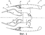
Как следует из фиг.1, предложенная гондола 1 для газотурбинного двигателя содержит кромку 2 воздухозаборника, среднюю структуру 3, охватывающую вентилятор 4 газотурбинного двигателя 5, и нижний по потоку узел 6. Нижний по потоку узел 6 включает в себя внутреннюю неподвижную структуру 7, которая охватывает верхнюю по потоку часть газотурбинного двигателя 5, внешнюю неподвижную структуру 8 и подвижный капот 9, в котором размещены средства реверса тяги.As follows from figure 1, the proposed
Как показано на фиг.2, предложенная кромка 2 воздухозаборника снабжена на некоторых своих участках акустической панелью 12, предназначенной для поглощения шумов, создаваемых при работе газотурбинного двигателя 5. Эта акустическая панель 12 включает в себя сотовую структуру 13, на которой закреплен перфорированный противообледенительный узел 14, и сплошную внутреннюю пленку 16. Противообледенительный узел 14 находится в контакте с потоком 18 холодного воздуха, тогда как внутренняя пленка 16 с этим потоком не контактирует.As shown in figure 2, the proposed
Акустическую панель 12 получают в ходе осуществления предлагаемого способа, содержащего следующие этапы:An acoustic panel 12 is obtained during the implementation of the proposed method, comprising the following steps:
A. создание внешней пленки, воспроизводящей линию обтекания кромки воздухозаборника;A. the creation of an external film that reproduces the line of flow around the edges of the air intake;
B. закрепление на указанной внешней пленке проводящего слоя, включающего в себя проводящие элементы;B. attaching a conductive layer including conductive elements to said outer film;
C. закрепление на указанном проводящем слое светочувствительного слоя, включающего в себя по меньшей мере один светочувствительный элемент;C. attaching to the specified conductive layer of the photosensitive layer, including at least one photosensitive element;
D. перфорирование полученного таким образом материала посредством перфорирующего средства с образованием акустических отверстий;D. perforating the material thus obtained by means of a perforating means to form acoustic holes;
E. наложение трафарета на светочувствительный слой материала, полученного на этапе D, для образования сетки из проводящих элементов, не закрывающих полученные на этапе D отверстия;E. applying a stencil to the photosensitive layer of the material obtained in step D to form a grid of conductive elements that do not cover the holes obtained in step D;
F. выявление указанной сетки методом фотолитографии;F. identification of the specified grid by photolithography;
G. электроизоляция поверхности сетки, полученной на этапе F;G. electrical insulation of the surface of the mesh obtained in step F;
H. закрепление на противообледенительном узле, полученном на этапе G, структуры с ячеистой сердцевиной;H. attaching to the de-icing unit obtained in step G, a honeycomb core structure;
I. наложение на полученный по завершении этапа H противообледенительный узел второй пленки с образованием тем самым акустической панели.I. applying an anti-icing unit to the second film obtained at the end of step H, thereby forming an acoustic panel.
Предложенный способ позволяет проще и с большей производительностью создавать акустическую панель, освобождаемую ото льда с использованием электрических средств, при этом количество ручных операций в нем существенно уменьшено. Это достигается благодаря тому, что перфорирование акустических отверстий в противообледенительном узле осуществляют до создания сетки из проводящих элементов. В результате, предложенный способ позволяет сэкономить время при изготовлении акустических панелей. Кроме того, он исключает возможность перекрытия акустических отверстий сеткой из проводящих элементов, а также возможность перфорирования сетки.The proposed method makes it easier and more efficient to create an acoustic panel that is freed from ice using electrical means, while the number of manual operations in it is significantly reduced. This is achieved due to the fact that the perforation of the acoustic holes in the anti-icing unit is carried out before creating a grid of conductive elements. As a result, the proposed method saves time in the manufacture of acoustic panels. In addition, it eliminates the possibility of overlapping acoustic holes with a mesh of conductive elements, as well as the possibility of perforating the mesh.
В дополнение к сказанному предложенный способ способен обеспечить любую известную геометрию сетки из проводящих элементов (т.е. группы проводящих элементов, расположенных последовательно и параллельно), что обуславливает неуязвимость сетки даже при повреждении ее некоторых проводящих частей. В результате, указанную геометрию можно выбирать с учетом распределения акустических отверстий, вследствие чего сетка оказывается максимально эффективной и это не препятствует оптимизации акустических характеристик панели. В соответствии с типовым вариантом изобретения, предлагаемый способ позволяет обеспечить расстояние между линиями сетки и расстояние до акустических отверстий около 0,3 мм.In addition to the above, the proposed method is capable of providing any known geometry of the mesh of conductive elements (i.e., a group of conductive elements arranged in series and parallel), which makes the mesh invulnerable even if some of its conductive parts are damaged. As a result, the indicated geometry can be selected taking into account the distribution of acoustic holes, as a result of which the grid is most effective and this does not prevent optimization of the acoustic characteristics of the panel. In accordance with a typical embodiment of the invention, the proposed method allows to provide a distance between grid lines and a distance to acoustic holes of about 0.3 mm.
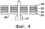
На этапе A предлагаемого способа создают внешнюю пленку 20, воспроизводящую линию обтекания кромки 2 воздухозаборника (см. фиг.3). Такую пленку можно получить с помощью любого соответствующего средства, известного из уровня техники.At stage A of the proposed method, an
Одно из преимуществ предложенного способа состоит в том, что он позволяет создавать такую акустическую панель 12, в которой очертания противообледенительного узла 14 по существу повторяют профиль кромки 2 воздухозаборника.One of the advantages of the proposed method is that it allows you to create such an acoustic panel 12, in which the outline of the anti-icing unit 14 essentially repeat the profile of the
Внешнюю пленку 20 можно изготовить путем формования, например, алюминиевого или титанового листа. В альтернативном случае ее можно получить методом драпировки складок ткани или однонаправленных углеродных и/или стеклянных волокон либо любого другого композитного материала, пригодного для реализации изобретения с использованием любой известной технологии.The
Можно также покрыть внешнюю пленку 20 каким-нибудь защитным элементом, например, наподобие краски или бронзовой сетки.You can also cover the
На этапе B предлагаемого способа, проиллюстрированного фиг.3, к указанной внешней пленке 20 прикрепляют проводящий слой 22, содержащий проводящие элементы.In step B of the proposed method, illustrated in FIG. 3, a
Проводящий слой 22 располагают на той поверхности внешней пленки 20, при нахождении на которой он может соприкасаться со структурой 13 с ячеистой сердцевиной. Другая поверхность этой пленки 20 предназначена для контактирования с потоком 18 холодного воздуха. Проводящий слой 22 может быть связан со стекловолоконной подложкой, получаемой из плоских пластинок, и разрезан таким образом, чтобы его можно было локально накладывать на кромку 2 воздухозаборника, несмотря на неразвертывающуюся форму.The
В предпочтительном случае проводящие элементы выбраны из группы, включающей медь, алюминий и/или медно-никелевый сплав. Такие элементы выделяют тепло при пропускании через них электрического тока. Для этого проводящий слой 22 соединяют с источником тока с помощью любого известного средства. Электрическое подсоединение проводящего слоя 22 можно выполнить за пределами акустической панели 12, проведя этот слой до нужного места. Питающие провода можно припаять непосредственно к проводящему слою 22 или же подсоединить через клеммы.Preferably, the conductive elements are selected from the group consisting of copper, aluminum and / or a copper-nickel alloy. Such elements generate heat when an electric current is passed through them. For this, the
Проводящий слой 22 накладывают на внешнюю пленку 20 непосредственно или же опосредовано, с присоединением к плоской гибкой подложке 24. Эта подложка 24 может содержать стеклянные волокна, в частности, стекловолоконные ткани с количеством складок от 1 до 3.The
В предпочтительном случае подложка 24 выполнена гибкой и может по существу принимать форму внешней пленки 20, по меньшей мере локально или же по всей ее поверхности. Благодаря такой подложке удается уменьшить число вырезов, которые необходимо сделать в материале, образованном проводящим слоем 22 и подложкой 24, для того чтобы эта подложка приняла форму внешней пленки 20. В результате достигается преимущество, состоящее в уменьшении числа этапов изготовления противообледенительного узла. Дело в том, что поскольку кромка 2 воздухозаборника имеет неразвертывающуюся форму, в случае, когда проводящий слой 22 выполнен из плоских пластинок, подложку 24 необходимо вырезать в форме расчески, что позволит выгнуть весь этот узел таким образом, чтобы подложка приняла форму внешней пленки 20.In a preferred case, the
Подложку 24 крепят к проводящему слою 22 с помощью любого известного средства, в частности клеем.The
На этапе C предлагаемого способа на проводящем слое 22 закрепляют светочувствительный слой 26, который содержит по меньшей мере один светочувствительный элемент, в частности, из светочувствительной смолы. Этот слой 26 может уже иметься в наличии в случае, если он выполнен на подложке, состоящей из плоских пластинок.In step C of the proposed method, a
На этапе D предлагаемого способа, проиллюстрированного фиг.4, сформированный указанным образом материал перфорируют перфорирующим средством 27, образуя акустические отверстия 28.In step D of the proposed method, illustrated in FIG. 4, the material formed in this way is perforated with a perforating means 27, forming
В качестве перфорирующего средства 27 можно использовать любое известное средство, пригодное для формирования акустических отверстий 28. Диаметр указанных отверстий 28 составляет, как правило, от 0,1 мм до 0,8 мм, предпочтительнее от 0,2 мм до 0,5 мм. При таких диаметрах акустических отверстий 28 удается обеспечить оптимальную акустическую поверхность панели 12.As the perforating means 27, any known means suitable for forming
В качестве примеров перфорирующего средства 27 можно привести многошпиндельный механический сверлильный станок, лазер или водобой. Перфорирование материала, полученного на этапах A, B и C, может быть произведено с внутренней или внешней сторон указанного материала, т.е. либо через поверхность светочувствительного слоя 26, либо через поверхность внешней пленки 20.As examples of the perforating means 27, a multi-spindle mechanical drilling machine, laser, or water spout can be mentioned. Perforation of the material obtained in steps A, B and C can be performed on the inside or outside of the specified material, i.e. either through the surface of the
На этапе E предлагаемого способа, проиллюстрированного фиг.5, на светочувствительный слой 26 материала, полученного на этапе D, накладывают трафарет 30, с тем чтобы сформировать сетку из проводящих элементов, не закрывающих выполненные на этапе D отверстия 28.In step E of the proposed method, illustrated in FIG. 5, a
Для примера укажем, что в качестве материала для трафарета 30 можно использовать любой известный прозрачный материал, пригодный для этих целей. В предпочтительном случае трафарет 30 представляет собой пленку на основе ксилола, например, марки mylar®.For example, we indicate that any known transparent material suitable for these purposes can be used as the material for the
В соответствии с предпочтительным альтернативным вариантом изобретения, перед этапом E предлагаемого способа на материал, полученный на этапе D, накладывают ряд центрирующих средств (не показаны), обеспечивающих надежное и точное позиционирование трафарета 30. В результате, становится возможным выполнить сетку из проводящих элементов очень точно, что позволяет исключить возможность перекрытия этих элементов с отверстиями 28.In accordance with a preferred alternative embodiment of the invention, before step E of the proposed method, a series of centering means (not shown) are applied to the material obtained in step D to ensure reliable and accurate positioning of the
Чтобы еще точнее позиционировать сетку из проводящих элементов относительно отверстий 28, положение трафарета 30 можно регулировать вручную.To more accurately position the grid of conductive elements relative to the
Операцию установки трафарета 30 можно упростить, если для каждого трафарета, накладываемого на полученный на этапе D материал, перфорировать (например вручную) по меньшей мере одно опорное отверстие (не показано), позволяющее установить по меньшей мере одно центрирующее средство. Эти опорные отверстия или отверстие могут быть совмещены с акустическим отверстием 32.The installation operation of the
После того как центрирующее средство станет уже ненужным, его можно снять. При этом опорное отверстие закрывают любым известным средством, пригодным для этих целей, с тем чтобы защитить акустическую поверхность. Однако можно и не закрывать это отверстие.Once the centering tool is no longer needed, it can be removed. In this case, the support hole is closed by any known means suitable for these purposes in order to protect the acoustic surface. However, you can not close this hole.
На этапе F предлагаемого способа из проводящих элементов выявляют сетку с применением метода фотолитографии.At stage F of the proposed method, a grid is detected from the conductive elements using the photolithography method.
Вначале полученный на этапе Е материал экспонируют, используя любое известное средство 32, пригодное для этих целей. В качестве примера можно назвать источники ультрафиолетового излучения.First, the material obtained in step E is exposed using any known means 32 suitable for this purpose. As an example, sources of ultraviolet radiation can be mentioned.
Светочувствительный слой 26, защищаемый рисунком 33, выполненным на трафарете 30, не затеняется УФ-излучением, что позволяет нанести этот рисунок на указанный слой. Что же касается незащищаемого слоя 26, то он затеняется.The
Экспонирование длится, как правило, несколько минут. Дело в том, что длительность экспонирования светочувствительного слоя 26 должна быть достаточно длительной, чтобы на этом слое пропечатался рисунок 33, но вместе с тем достаточно короткой, чтобы не допустить прохождения УФ-лучей по всей площади поверхности трафарета 30, в каковом случае любой рисунок будет стерт.Exposure usually lasts a few minutes. The fact is that the exposure time of the
После этого незащищенный слой 26 удаляют с помощью любого известного пригодного проявителя. В качестве примера можно назвать каустическую соду.Thereafter, the
В результате, как видно на фиг.6, оставшийся светочувствительный слой 26 будет воспроизводить нужный рисунок сетки.As a result, as can be seen in FIG. 6, the remaining
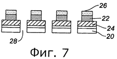
Далее применяют любое известное специалистам и пригодное для этих целей химическое вещество для удаления части 34 проводящего слоя, которая не находится под оставшимся светочувствительным слоем 26. В результате, как показано на фиг.7, остается лишь та часть проводящего слоя 22, которая находится под рисунком, образованным светочувствительным слоем 26.Then, any chemical known to those skilled in the art and suitable for these purposes is used to remove part of the
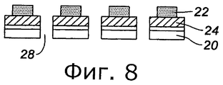
После этого оставшийся светочувствительный слой 26 удаляют с помощью любого известного и пригодного для этих целей химического вещества таким образом, чтобы рисунок сетки из проводящих элементов воспроизводился проводящим слоем 22 (см. фиг.8 и 9).After that, the remaining
На этапе G предлагаемого способа выполняют электроизоляцию поверхности сетки, полученной на этапе F (см. фиг.10). В ходе этой электроизоляции удается обеспечить теплоизоляцию указанной сетки.At step G of the proposed method, electrical insulation of the surface of the mesh obtained in step F is performed (see FIG. 10). During this electrical insulation, it is possible to provide thermal insulation of the specified mesh.
Проводящие элементы, образующие проводящий слой 22, как правило, чувствительны к окислению, поэтому они нуждаются в защите.The conductive elements forming the
В предпочтительном случае электроизоляцию производят путем точного нанесения оксидного слоя, что позволяет добиться его избирательного нанесения на сетку (т.е. на проводящие элементы) без перекрытия акустических отверстий 28. В качестве примера укажем, что нанесение можно осуществлять путем электролиза в случаях, когда сетка выполнена из алюминия. Алюминиевый слой может быть нанесен методом анодирования.In the preferred case, the electrical insulation is carried out by precise deposition of the oxide layer, which allows it to be selectively applied to the grid (ie, to the conductive elements) without overlapping the
Толщина оксидного слоя составляет от 1 мкм до 0,05 мм, в частности 0,01 мм.The thickness of the oxide layer is from 1 μm to 0.05 mm, in particular 0.01 mm
В качестве примера используемого оксидного слоя можно назвать оксид алюминия (если проводящие элементы выполнены из алюминия), который обеспечивает оптимальную изоляцию.As an example of the oxide layer used, aluminum oxide (if the conductive elements are made of aluminum), which provides optimal insulation, can be mentioned.
Защиту можно также обеспечить путем нанесения любого защитного материала типа лака, предусматривая вначале избирательную защиту опорных и акустических отверстий посредством нанесения слоя светочувствительных элементов с применением того же метода фотолитографии, что и описанный выше. Благодаря такой технологии удается защитить все проводящие элементы без перекрытия опорных и акустических отверстий.Protection can also be achieved by applying any protective material such as varnish, first providing selective protection of the support and acoustic holes by applying a layer of photosensitive elements using the same photolithography method as described above. Thanks to this technology, it is possible to protect all conductive elements without overlapping support and acoustic holes.
Как показано на фиг.11, на этапе H предлагаемого способа на противообледенительном узле 14, полученном на этапе G, закрепляют структуру 13 с ячеистой сердцевиной. В предпочтительном случае в качестве этой структуры применяют структуру сотового типа.As shown in FIG. 11, in step H of the proposed method, a
Это крепление можно осуществить любым известным методом, но предпочтительно приклеиванием.This fastening can be carried out by any known method, but preferably by gluing.
В соответствии с первым вариантом осуществления, на кромки сот наносят клеевую пленку, которая позволяет приклеить сотовую структуру 13 к полученному на этапе G противообледенительному узлу 14, а также улучшает электро- и теплоизоляцию проводящих элементов.In accordance with the first embodiment, an adhesive film is applied to the edges of the cells, which allows the
В соответствии с предпочтительным вариантом изобретения, проиллюстрированным на фиг.11, клей 42 наносят на сетку из проводящих элементов путем продувания сжатого воздуха через акустические отверстия 28. Эту процедуру осуществляют только, если диаметр отверстий достаточен для обеспечения надлежащего пропускания нагнетаемого воздуха, поскольку в этом случае предотвращается забивание акустических отверстий 28 клеем 42. В качестве примера используемого клея можно назвать клей на эпоксидной основе типа Redux 322®.In accordance with the preferred embodiment of the invention illustrated in FIG. 11,
На этапе I предлагаемого способа на противообледенительный узел, полученный на этапе H, наносят вторую пленку 16, образуя тем самым акустическую панель 12.In step I of the proposed method, a second film 16 is applied to the de-icing assembly obtained in step H, thereby forming an acoustic panel 12.
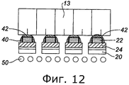
В соответствии с предпочтительным вариантом, проиллюстрированным на фиг.12, на внешнюю пленку 20 накладывают металлическую сетку 50, в частности, путем приклеивания. Эта сетка 50 предназначена для снижения аэродинамических потерь, обусловленных взаимодействием внешнего потока с внутренней поверхностью акустических отверстий 28. Преимущество использования такой сетки состоит в том, что она позволяет выполнять акустические отверстия 28 с диаметром от 1,3 мм до 2,2 мм, предпочтительнее от 1,5 мм до 2 мм, без создания аэродинамических проблем. Другое преимущество металлической сетки 50 состоит в защите кромки 2 воздухозаборника от грозовых разрядов.In accordance with the preferred embodiment illustrated in FIG. 12, a
В части 44 кромки воздухозаборника, не подвергнутой акустической обработке и не содержащей сотовую структуру 13, можно при необходимости закрепить на противообледенительном узле 14 с помощью любого известного средства обычный защитный изолирующий материал (см. фиг.2). В качестве примера такого материала можно назвать композитную пленку, имеющую высокую конструктивную прочность.In part 44 of the edge of the air intake, not subjected to acoustic processing and not containing a
Можно также предусмотреть отжиг полученной на этапе I акустической панели 12 при температуре, составляющей обычно от 170 до 180°C или же около 175°C, что позволит повысить прочность акустической панели 12.You can also provide annealing obtained in stage I of the acoustic panel 12 at a temperature of usually from 170 to 180 ° C or about 175 ° C, which will increase the strength of the acoustic panel 12.
Claims (15)
A. создание внешней пленки (20), воспроизводящей линию обтекания кромки (2) воздухозаборника;
B. закрепление на указанной внешней пленке (20) проводящего слоя (22), включающего в себя проводящие элементы;
C. закрепление на указанном проводящем слое (22) светочувствительного слоя (26), включающего в себя по меньшей мере один светочувствительный элемент;
D. перфорирование полученного таким образом материала посредством перфорирующего средства (27) с образованием акустических отверстий (28);
E. наложение трафарета (30) на светочувствительный слой (26) материала, полученного по завершении этапа D, для образования сетки из проводящих элементов, не закрывающих полученные на этапе D отверстия (28);
F. выявление указанной сетки методом фотолитографии;
G. электроизоляция поверхности сетки, полученной на этапе F;
H. закрепление на противообледенительном узле (14), полученном на этапе G, структуры (13) с ячеистой сердцевиной;
I. наложение на полученный по завершении этапа Н противообледенительный узел (14) второй пленки (16) с образованием тем самым акустической панели (12).1. A method of manufacturing an acoustic panel (12) for the edge (2) of the air intake of the nacelle (1), comprising the following steps:
A. creating an external film (20) that reproduces the line of flow around the edge (2) of the air intake;
B. attaching a conductive layer (22) including conductive elements to said outer film (20);
C. fixing on the specified conductive layer (22) of the photosensitive layer (26), which includes at least one photosensitive element;
D. perforating the material thus obtained by means of a perforating means (27) with the formation of acoustic holes (28);
E. applying a stencil (30) to the photosensitive layer (26) of the material obtained at the end of step D to form a grid of conductive elements that do not cover the holes (28) obtained in step D;
F. identification of the specified grid by photolithography;
G. electrical insulation of the surface of the mesh obtained in step F;
H. fastening on the de-icing unit (14) obtained in step G, a structure (13) with a cellular core;
I. application of the second film (16) onto the anti-icing unit (14) obtained at the end of stage H, thereby forming an acoustic panel (12).
Applications Claiming Priority (3)
| Application Number | Priority Date | Filing Date | Title |
|---|---|---|---|
| FR0804823A FR2935356B1 (en) | 2008-09-03 | 2008-09-03 | METHOD FOR MANUFACTURING AN ACOUSTIC PANEL OF AN AIR INLET LAUNCHER OF A NACELLE |
| FR08/04823 | 2008-09-03 | ||
| PCT/FR2009/001009 WO2010026305A1 (en) | 2008-09-03 | 2009-08-14 | Method for making an acoustic panel for the air intake lip of a nacelle |
Publications (2)
| Publication Number | Publication Date |
|---|---|
| RU2011111341A RU2011111341A (en) | 2012-10-10 |
| RU2500580C2 true RU2500580C2 (en) | 2013-12-10 |
Family
ID=40488393
Family Applications (1)
| Application Number | Title | Priority Date | Filing Date |
|---|---|---|---|
| RU2011111341/11A RU2500580C2 (en) | 2008-09-03 | 2009-08-14 | Method of making acoustic panel for nacelle air intake |
Country Status (9)
| Country | Link |
|---|---|
| US (1) | US8584363B2 (en) |
| EP (1) | EP2321179B1 (en) |
| CN (1) | CN102143889B (en) |
| BR (1) | BRPI0918600A2 (en) |
| CA (1) | CA2733701A1 (en) |
| ES (1) | ES2457531T3 (en) |
| FR (1) | FR2935356B1 (en) |
| RU (1) | RU2500580C2 (en) |
| WO (1) | WO2010026305A1 (en) |
Families Citing this family (18)
| Publication number | Priority date | Publication date | Assignee | Title |
|---|---|---|---|---|
| FR2935357B1 (en) * | 2008-09-03 | 2010-08-27 | Aircelle Sa | METHOD FOR MANUFACTURING A NACELLE ELEMENT |
| FR2980775B1 (en) * | 2011-10-03 | 2014-07-11 | Airbus Operations Sas | AIRCRAFT NACELLE COMPRISING A PANEL FOR ACOUSTIC TREATMENT INTEGRATING HOT AIR CHANNELS AND AT LEAST ONE STABILIZING CHAMBER |
| US8998144B2 (en) * | 2012-02-06 | 2015-04-07 | Textron Innovations Inc. | Thermal insulation barrier for an aircraft de-icing heater |
| FR2992291B1 (en) * | 2012-06-25 | 2016-03-04 | Aircelle Sa | HEATED ELECTRICAL ASSEMBLY FOR DEFROSTING DEVICE |
| US8919494B2 (en) * | 2012-07-31 | 2014-12-30 | Rohr, Inc. | Electric heater for integration into an aircraft acoustic panel |
| JP2014050864A (en) * | 2012-09-07 | 2014-03-20 | Dainippon Printing Co Ltd | Laser processing machine for labels |
| ITTO20121152A1 (en) * | 2012-12-27 | 2014-06-28 | Alenia Aermacchi Spa | MOTOR GONDOLA FOR AN AIRCRAFT, EQUIPPED WITH AN INTEGRATED PROTECTION SYSTEM FOR ANTI-ICE AND ACOUSTIC ABSORPTION. |
| US10501165B2 (en) | 2014-12-18 | 2019-12-10 | Bombardier Inc. | Sound absorbers for airframe components |
| FR3061132B1 (en) * | 2016-12-27 | 2023-11-03 | Airbus Operations Sas | STRUCTURE FOR AIRCRAFT PROPULSIVE ASSEMBLY, ASSOCIATED SYSTEM AND PROPULSION ASSEMBLY |
| FR3079818A1 (en) * | 2018-04-10 | 2019-10-11 | Airbus Operations (S.A.S.) | AIRCRAFT ENGINE NACELLE WITH A FROST PROTECTIVE SYSTEM AND METHOD FOR PROTECTING THE SAME |
| CN109050869A (en) * | 2018-07-17 | 2018-12-21 | 中国航空工业集团公司沈阳飞机设计研究所 | A kind of ram-air bleed structure |
| FR3086786B1 (en) * | 2018-10-01 | 2020-12-18 | Airbus Operations Sas | PROCESS FOR MANUFACTURING AN ACOUSTIC DE-ICING SKIN FOR AN AIRCRAFT ACOUSTIC PANEL, USING A FIBER SPREADING DEVICE |
| FR3092871B1 (en) * | 2019-02-15 | 2022-02-25 | Airbus Operations Sas | METHOD FOR ASSEMBLING AN AIR INTAKE OF AN AIRCRAFT TURBOJET |
| FR3100842A1 (en) * | 2019-09-12 | 2021-03-19 | Airbus Operations | Air inlet, nacelle, propulsion assembly and grooved lip aircraft |
| FR3115829B1 (en) * | 2020-11-05 | 2022-10-14 | Safran Nacelles | Fixing an exhaust cone in a turbomachine nozzle |
| CN114162336B (en) * | 2021-12-14 | 2024-01-05 | 北京机电工程研究所 | Stealth air inlet channel of aircraft radar and preparation method thereof |
| FR3130754A1 (en) * | 2021-12-17 | 2023-06-23 | Safran Nacelles | AIR INTAKE LIP FOR A NACELLE OF AN AIRCRAFT PROPULSION ASSEMBLY |
| CN114162331B (en) * | 2022-02-14 | 2022-04-29 | 中国空气动力研究与发展中心低速空气动力研究所 | Icing detection device and icing detection method |
Citations (3)
| Publication number | Priority date | Publication date | Assignee | Title |
|---|---|---|---|---|
| GB885131A (en) * | 1958-04-24 | 1961-12-20 | Goodrich Co B F | Apparatus for and method of making a heating structure |
| RU2226481C2 (en) * | 2002-07-19 | 2004-04-10 | Открытое акционерное общество "Казанский вертолётный завод" | Electro-thermal de-icing system for helicopter blades |
| EP1826119A2 (en) * | 2006-02-24 | 2007-08-29 | Goodrich Corporation | Composite ice protection heater and method of producing same |
Family Cites Families (11)
| Publication number | Priority date | Publication date | Assignee | Title |
|---|---|---|---|---|
| ATA331285A (en) * | 1985-11-13 | 1988-11-15 | Ims Ionen Mikrofab Syst | METHOD FOR PRODUCING A TRANSMISSION MASK |
| FR2733871B1 (en) * | 1995-05-04 | 1997-06-06 | Norton Pampus Gmbh | HEATING ELEMENT, MANUFACTURING METHOD AND APPLICATION |
| GB9613615D0 (en) * | 1996-06-28 | 1996-08-28 | Short Brothers Plc | Method of manufacturing a noise attenuation panel |
| US6371411B1 (en) * | 1999-11-23 | 2002-04-16 | The Boeing Company | Method and apparatus for aircraft inlet ice protection |
| US7588212B2 (en) * | 2003-07-08 | 2009-09-15 | Rohr Inc. | Method and apparatus for noise abatement and ice protection of an aircraft engine nacelle inlet lip |
| US7824824B2 (en) * | 2005-03-08 | 2010-11-02 | Texas Instruments Incorporated | Composite phase shifting lithography mask including etch stop layer |
| FR2887519B1 (en) * | 2005-06-22 | 2008-10-10 | Airbus France Sas | ANTI-FRICTION AND DEFROSTING SYSTEM OF AN AIRCRAFT ENGINE NACELLE WITH RESISTIVE CARPETS |
| DE102006031330B4 (en) * | 2005-07-14 | 2014-03-20 | Goodrich Corp. | An ice-susceptible portion of an aircraft, in particular an aircraft engine cell inlet lip, comprising an ice protection system, aircraft engine having such an inlet lip, and a method of protecting such inlet lip from icing |
| US7923668B2 (en) * | 2006-02-24 | 2011-04-12 | Rohr, Inc. | Acoustic nacelle inlet lip having composite construction and an integral electric ice protection heater disposed therein |
| FR2908737B1 (en) * | 2006-11-16 | 2009-12-04 | Airbus France | ACOUSTIC COATING FOR AIRCRAFT INCORPORATING A JELLY EFFECT FROST TREATMENT SYSTEM. |
| DE102009000642B4 (en) * | 2009-02-05 | 2012-12-06 | BAM Bundesanstalt für Materialforschung und -prüfung | Process for producing microstructured components by means of photolithography |
-
2008
- 2008-09-03 FR FR0804823A patent/FR2935356B1/en not_active Expired - Fee Related
-
2009
- 2009-08-14 CA CA2733701A patent/CA2733701A1/en not_active Abandoned
- 2009-08-14 WO PCT/FR2009/001009 patent/WO2010026305A1/en active Application Filing
- 2009-08-14 ES ES09737017.5T patent/ES2457531T3/en active Active
- 2009-08-14 CN CN2009801345251A patent/CN102143889B/en not_active Expired - Fee Related
- 2009-08-14 RU RU2011111341/11A patent/RU2500580C2/en not_active IP Right Cessation
- 2009-08-14 US US13/062,104 patent/US8584363B2/en not_active Expired - Fee Related
- 2009-08-14 EP EP09737017.5A patent/EP2321179B1/en active Active
- 2009-08-14 BR BRPI0918600A patent/BRPI0918600A2/en not_active IP Right Cessation
Patent Citations (3)
| Publication number | Priority date | Publication date | Assignee | Title |
|---|---|---|---|---|
| GB885131A (en) * | 1958-04-24 | 1961-12-20 | Goodrich Co B F | Apparatus for and method of making a heating structure |
| RU2226481C2 (en) * | 2002-07-19 | 2004-04-10 | Открытое акционерное общество "Казанский вертолётный завод" | Electro-thermal de-icing system for helicopter blades |
| EP1826119A2 (en) * | 2006-02-24 | 2007-08-29 | Goodrich Corporation | Composite ice protection heater and method of producing same |
Also Published As
| Publication number | Publication date |
|---|---|
| EP2321179B1 (en) | 2014-01-15 |
| US20110155855A1 (en) | 2011-06-30 |
| CA2733701A1 (en) | 2010-03-11 |
| WO2010026305A1 (en) | 2010-03-11 |
| BRPI0918600A2 (en) | 2015-12-15 |
| RU2011111341A (en) | 2012-10-10 |
| CN102143889B (en) | 2013-12-25 |
| FR2935356B1 (en) | 2010-08-27 |
| EP2321179A1 (en) | 2011-05-18 |
| FR2935356A1 (en) | 2010-03-05 |
| ES2457531T3 (en) | 2014-04-28 |
| US8584363B2 (en) | 2013-11-19 |
| CN102143889A (en) | 2011-08-03 |
Similar Documents
| Publication | Publication Date | Title |
|---|---|---|
| RU2500580C2 (en) | Method of making acoustic panel for nacelle air intake | |
| RU2500581C2 (en) | Method of nacelle deicing element fabrication | |
| JP5224607B2 (en) | Aircraft silencer coating with built-in Joule effect frost treatment system | |
| RU2422331C2 (en) | Section of gondola air intake edge with electric ice protection and acoustic absorption zone | |
| RU2509686C2 (en) | Method of arranging anti-icing system at nacelle panel | |
| US7946385B2 (en) | Process for the production of an acoustically resistive structure, the acoustically resistive structure thus obtained, and coating using such a structure | |
| US4743740A (en) | Buried element deicer | |
| EP2938540B1 (en) | Nacelle for aircraft, provided with a built-in system for anti-icing protection and acoustic absorption | |
| CN105523175B (en) | Perforated surface for suction lamination flow control | |
| JP5933919B2 (en) | Turbomachine nacelle, anti-icing system and method thereof | |
| RU2500585C2 (en) | Turbojet nacelle air intake | |
| CA2725696A1 (en) | Turbomachine nacelle and anti-icing system and method therefor | |
| BR102013019573A2 (en) | electric heater for integration into an acoustic panel, method of manufacturing an electric heater, and acoustic panel | |
| EP1925551A1 (en) | Ice protection system with noise abatement | |
| US11242150B2 (en) | Anti-icing system for an aircraft |
Legal Events
| Date | Code | Title | Description |
|---|---|---|---|
| MM4A | The patent is invalid due to non-payment of fees |
Effective date: 20150815 |