RU2500569C2 - Method of outsize underwater structures transfer and complex to this end - Google Patents
Method of outsize underwater structures transfer and complex to this end Download PDFInfo
- Publication number
- RU2500569C2 RU2500569C2 RU2011141142/11A RU2011141142A RU2500569C2 RU 2500569 C2 RU2500569 C2 RU 2500569C2 RU 2011141142/11 A RU2011141142/11 A RU 2011141142/11A RU 2011141142 A RU2011141142 A RU 2011141142A RU 2500569 C2 RU2500569 C2 RU 2500569C2
- Authority
- RU
- Russia
- Prior art keywords
- underwater
- transportation
- floating bodies
- self
- coaming
- Prior art date
Links
Images


Abstract
Description
Изобретение относится к области судостроения и касается вопросов создания средств для осуществления подводных подъемно-транспортных операций с негабаритными подводными объектами, в том числе, подо льдом без всплытия на поверхность.The invention relates to the field of shipbuilding and concerns the creation of means for carrying out underwater lifting and transport operations with oversized underwater objects, including under ice without surfacing.
Выполнение транспортных операций с негабаритными грузами в условиях арктического шельфа РФ, так же как в других регионах, где продолжительность межледового периода составляет малую часть года, представляет собой актуальную задачу в связи с необходимостью круглогодичного производства работ по обустройству и обслуживанию подводных добычных систем, ремонту объектов инфраструктуры и т.д. Предыстория развития подводных промысловых технологий связана, главным образом, с освоением акваторий, где лед, либо отсутствует, либо его присутствие не является существенным фактором при выборе технических решений для морских технических средств. Тем не менее, современные подводные технологии, по крайней мере на первых порах могут быть практически без изменений перенесены в ледовитые акватории. Спектр массогабаритных параметров возможных объектов подводной транспортировки весьма широк, поэтому выбор оптимальных параметров транспортных средств представляет собой сложную задачу. Очевидно, что традиционная архитектура подводных транспортных средств (разрабатываемая примерно с 60-х гг. 20-го века), которая предполагает размещение транспортируемого объекта на бору подводных судов существенно ограничивает возможности оптимизации подводной транспортной системы. Более того, необходимость интеграции приводит к распространению ограничений, связанных с традиционной архитектурой подводных транспортных средств, на «большую» систему, которая включает транспортные средства и технологические средства обеспечения промысловой деятельности на шельфе. Очевидно, что полное покрытие всего спектра массогабаритных параметров возможных объектов подводной транспортировки основными средствами традиционной архитектуры неизбежно приведет к избыточности параметров, как самих средств транспортировки, так и транспортной системы, построенной на их основе. Прежде всего, избыточность выразится в неадекватно большом водоизмещении подводных транспортных средств со всеми вытекающими последствиями в плане эффективности применения, стоимости жизненного цикла и т.д. В то же время, известно, что соотношение массы и габаритов подводных объектов транспортировки таково, что их удельная масса (масса отнесенная к объему занимаемого пространства) в подавляющем большинстве случаев весьма существенно меньше плотности собственно конструкционных материалов из которых они изготовлены. Низкая удельная масса крупногабаритных конструкций обеспечивает возможность их транспортировки на плаву и широко используется во многих технологиях, например, при строительстве, причальных и защитных сооружений, морских гравитационных платформ и т.д. Известны технические решения, направленные на сообщение объектам транспортировки дополнительной плавучести, в случае нехватки собственной и т.д. Актуализация собственной плавучести в области подводных транспортных операций имеет место в технологии судоподъема. Известно большое количество прецедентов и запатентованных технических решений, основанных на восстановлении собственной плавучести, например, пат. №2249533, №22270134, №2005129355 A и т.п. При этом важнейшим преимуществом транспортных технологий основанных на использовании собственной плавучести объекта транспортировки, например, в области судоподъема является возможность осуществлять подъем крупных объектов, используя сравнительно маломощные подъемные и транспортные средства. Основные вопросы реализации таких технологий связаны с обеспечением герметичности внутренних объемов объекта операции, а в более широком смысле с проблемой удержания плавучего вещества или плавучих тел внутри подводного (затонувшего) объекта. Известны различные способы решения этой задачи, среди которых примерно с середины 60-х гг. прошлого века занимает способ заполнения внутреннего пространства подводного объекта множеством плавучих тел, который снимает проблему герметизации как таковую. Впервые на практике способ был применен компанией «Вейсмюллер» в 60-е гг. прошлого века. В настоящее время способ применяется в судоподъемных операциях, для поддержания на плаву утилизируемых АЛЛ и т.д. Однако распространение способа связано с трудностями. В частности, при выгрузке плавучего материала из объектов (пат. РФ №2230001). Также не имеют широкого распространения технические средства доставки множества плавучих тел внутрь объекта, находящегося на глубине и т.д.The performance of transport operations with oversized cargo in the Arctic shelf of the Russian Federation, as well as in other regions where the inter-ice period is a small part of the year, is an urgent task due to the need for year-round work on the arrangement and maintenance of underwater mining systems, repair of infrastructure facilities etc. The prehistory of the development of underwater fishing technologies is mainly related to the development of water areas where ice is either absent or its presence is not a significant factor in the selection of technical solutions for marine technical means. Nevertheless, modern underwater technologies, at least initially, can be practically unchanged transferred to the Arctic waters. The range of weight and size parameters of possible underwater transportation facilities is very wide, so the choice of the optimal vehicle parameters is a difficult task. Obviously, the traditional architecture of underwater vehicles (developed with about 60-ies. 20 th century), which involves the placement of an object transported on forest submarine vessels significantly limits the possibility of optimizing subsea transport system. Moreover, the need for integration leads to the extension of the limitations associated with the traditional architecture of submarine vehicles to the “large” system, which includes vehicles and technological means of supporting offshore fishing activities. Obviously, the full coverage of the entire spectrum of weight and size parameters of possible underwater transportation facilities with the main means of traditional architecture will inevitably lead to redundancy of the parameters of both the means of transportation and the transport system built on their basis. First of all, redundancy will be expressed in an inadequately large displacement of underwater vehicles with all the ensuing consequences in terms of application efficiency, life cycle cost, etc. At the same time, it is known that the ratio of the mass and dimensions of underwater transportation objects is such that their specific gravity (mass referred to the volume of occupied space) in the vast majority of cases is very much lower than the density of the structural materials from which they are made. The low specific gravity of large-sized structures makes it possible to transport them afloat and is widely used in many technologies, for example, in construction, berthing and protective structures, offshore gravity platforms, etc. Known technical solutions aimed at communicating additional buoyancy to transportation facilities in the event of a shortage of their own, etc. The actualization of own buoyancy in the field of underwater transport operations takes place in the technology of ship lifting. A large number of precedents and patented technical solutions based on the restoration of its own buoyancy, for example, US Pat. No. 22429533, No. 22270134, No. 2005129355 A, etc. At the same time, the most important advantage of transport technologies based on the use of the buoyancy of the transportation object, for example, in the field of ship lifting, is the ability to lift large objects using relatively low-power lifting and transport vehicles. The main issues related to the implementation of such technologies are related to ensuring the tightness of the internal volumes of the operation object, and in a broader sense, the problem of retaining floating material or floating bodies inside an underwater (sunken) object. There are various ways to solve this problem, among which approximately since the mid 60 - ies. of the last century, a method for filling the internal space of an underwater object with a lot of floating bodies, which removes the problem of sealing as such, takes up. For the first time in the practice of the method has been used by "Veysmyuller" in the 60 th years. last century. Currently, the method is used in ship lifting operations, to maintain afloat utilized ALL, etc. However, the spread of the method is associated with difficulties. In particular, when unloading floating material from objects (US Pat. RF No. 2230001). Also, technical means of delivering many floating bodies inside an object located at a depth, etc., are not widely used.
В различных областях техники и технологии в настоящее время существуют известные технические решения, совокупность которых создает предпосылки для развития технических средств транспортировки подводных объектов дополняющих, а в случае необходимости заменяющих подводные средства традиционной архитектуры. С учетом, специфики проблем транспортного обеспечения подводных промысловых технологий, в частности, на арктическом шельфе, адаптация и распространение известных технических решений на область подводных транспортных технологий может обеспечить существенные преимущества.In various fields of engineering and technology, currently there are well-known technical solutions, the combination of which creates the prerequisites for the development of technical means of transportation of underwater objects complementing and, if necessary, replacing underwater means of traditional architecture. Given the specifics of the problems of transport support for underwater fishing technologies, in particular, on the Arctic shelf, the adaptation and distribution of well-known technical solutions to the field of underwater transport technologies can provide significant advantages.
В настоящее время можно констатировать следующее:Currently, we can state the following:
1. Подавляющее большинство известных технических решений в области транспортировки подводных объектов предполагает применение надводных технических средств, что вполне объяснимо отсутствием экономически обоснованной потребности в решении задачи подводной транспортировки. Известные проектные проработки, выполненные в этом направлении, до настоящего времени не реализованы нигде в мире. Вопрос о необходимости подводной транспортировки грузов оказался в практической плоскости лишь в связи с необходимостью освоения углеводородных ресурсов арктического шельфа.1. The vast majority of well-known technical solutions in the field of transportation of underwater objects involves the use of surface technical means, which is quite understandable by the absence of an economically justified need for solving the problem of underwater transportation. Well-known design studies carried out in this direction have not yet been implemented anywhere in the world. The question of the need for underwater transportation of goods appeared on the practical plane only in connection with the need to develop hydrocarbon resources of the Arctic shelf.
2. Подавляющее большинство технических решений в области подводной транспортировки грузов направлено не на изменение собственных функциональных свойств груза, а на компенсацию веса объекта как действующего фактора за счет свойств транспортных средств, что приводит росту массогабаритных параметров их грузонесущих и грузозахватных конструкций, а также водоизмещения транспортных средств в целом.2. The vast majority of technical solutions in the field of underwater transportation of goods is not aimed at changing the cargo’s own functional properties, but at compensating the object’s weight as an acting factor due to the properties of vehicles, which leads to an increase in the weight and size parameters of their load-bearing and load-bearing structures, as well as vehicle displacement generally.
3. Альтернативное техническое решение состоит в снижение подводного веса объекта операции. В области судоподъема подобное техническое решение широко известно.3. An alternative technical solution consists in reducing the underwater weight of the object of operation. In the field of ship lifting, such a technical solution is widely known.
4. Главными проблемами, при компенсации подводного веса объекта транспортировки являются:4. The main problems when compensating for the underwater weight of the transportation object are:
- ограниченность прочности плавучих тел, используемых для сообщения необходимой плавучести подводного объекта;- limited strength of the floating bodies used to communicate the necessary buoyancy of the underwater object;
- сложность доставки плавучих тел на глубину расположения объекта и обеспечение необходимого, с точки зрения условий равновесия, распределения плавучих тел в пространстве;- the difficulty of delivering floating bodies to the depth of the object and providing the necessary, in terms of equilibrium conditions, distribution of floating bodies in space;
- обеспечение совместного действия сил плавучести множества плавучих тел;- ensuring the joint action of the buoyancy forces of many floating bodies;
- обеспечение сохранности плавучих тел в целях повторного их использования и предотвращения засорения акватории и т.д.- ensuring the safety of floating bodies in order to reuse them and prevent clogging of the water area, etc.
В отсутствие прямых аналогов наиболее близкие частные технические решения, относящиеся к области транспортировки негабаритных подводных объектов, относятся к области судоподъема.In the absence of direct analogues, the closest private technical solutions related to the transportation of oversized underwater objects relate to the area of ship lifting.
Известно техническое решение «Комплекс для подъема затонувших объектов» (пат. РФ №2081026 опубликовано 10.06.1997) - принято за прототип. Комплекс включает две подводные лодки и функционирует следующим образом. После обнаружения затонувшего объекта, например подводной лодки, комплекс опускается на дно рядом с объектом. С помощью двух подводных лодок, входящих в комплекс, под объект заводят подъемную платформу, расположенную между ними. Точнее платформу, растянутую между подводными лодками комплекса, так как платформа представляет собой гибкую конструкцию из параллельных тросов, на каждый из которых насажены плавучие сферические элементы. После опускания объекта на платформу осуществляют сброс балластных грузов с подводных лодок и тем самым обеспечивают подъем затонувшего объекта на поверхность.Known technical solution "Complex for lifting sunken objects" (US Pat. RF No. 2081026 published 10.06.1997) - taken as a prototype. The complex includes two submarines and operates as follows. After the discovery of a sunken object, such as a submarine, the complex sinks to the bottom next to the object. With the help of two submarines included in the complex, a lifting platform is placed under the object located between them. More precisely, the platform stretched between the submarines of the complex, since the platform is a flexible structure of parallel cables, each of which has floating spherical elements. After lowering the object onto the platform, ballast weights are discharged from the submarines and thereby ensure that the sunken object is lifted to the surface.
Основными недостатками прототипа является следующие:The main disadvantages of the prototype are the following:
1. Комплекс практически невозможно использовать для перемещения объектов в толще воды, так величина постоянной подъемной силы плавучих тел заведомо должна превышать подводный вес объекта. Поэтому будет иметь место постоянное вертикальное движение комплекса с объектом к поверхности акватории.1. The complex is almost impossible to use to move objects in the water column, so the value of the constant lifting force of floating bodies must obviously exceed the underwater weight of the object. Therefore, there will be a constant vertical movement of the complex with the object to the surface of the water area.
2. Для нормального функционирования комплекса необходимо равенство веса подводного объекта, плавучести подъемной платформы и подводного веса сбрасываемых грузов. Чтобы использовать различные сбрасываемые балластные грузы, подводные лодки комплекса должны иметь достаточно большие прочные компенсационные цистерны для обеспечения нулевой собственной плавучести в широком диапазоне весов сбрасываемых грузов (равных по величине весам различных объектов транспортировки). Наличие упомянутых компенсационных цистерн в прототипе не предусмотрено.2. For the normal functioning of the complex, it is necessary to equal the weight of the underwater object, the buoyancy of the lifting platform and the underwater weight of the dumped cargo. In order to use various discharged ballast weights, the complex’s submarines must have sufficiently strong strong compensation tanks to ensure zero intrinsic buoyancy in a wide range of weights of discharged goods (equal in magnitude to the weights of various transportation objects). The presence of the mentioned compensation tanks in the prototype is not provided.
3. Изменение плавучести подъемной платформы возможно лишь за счет изменения количества и плавучих тел на тросах платформы, что возможно лишь путем ее перемонтажа перед каждой операцией. Это существенно снижает эффективность комплекса, так как требует производства достаточно сложного технологического процесса, привлечения плавсредств и т.д.3. Changing the buoyancy of the lifting platform is possible only by changing the number and floating bodies on the platform cables, which is only possible by re-mounting it before each operation. This significantly reduces the effectiveness of the complex, as it requires the production of a fairly complex process, attracting watercraft, etc.
4. Конструкция платформы не предусматривает фиксацию плавучих тел по длине тросов, что делает невозможным создание необходимого по условиям статики распределения суммарной подъемной силы.4. The design of the platform does not provide for the fixation of floating bodies along the length of the cables, which makes it impossible to create the distribution of the total lifting force required by the static conditions.
5. Комплекс даже теоретически невозможно использовать на стадии установки на грунт подводного объекта, доставленного к месту назначения, так как после расцепления платформы с объектом она неуправляемо всплывет вместе с подводными лодками, к которым она прикреплена и т.д.5. The complex is even theoretically impossible to use at the stage of installation on the ground of an underwater object delivered to its destination, because after the platform and the object are disengaged, it will uncontrollably emerge along with the submarines to which it is attached, etc.
Задачей предлагаемого изобретения является обеспечение независимости процесса транспортировки подводных объектов от наличия и состояния ледового покрова акватории, минимизация водоизмещения подводных транспортных средств, универсализация комплекса в отношении массы и габаритов транспортируемых негабаритных подводных объектов, упрощение и удешевление эксплуатации комплекса, упрощение и удешевление модернизации комплекса, улучшение экологических параметров комплекса.The objective of the invention is to ensure the independence of the transportation of underwater objects from the presence and condition of the ice cover of the water area, minimize the displacement of underwater vehicles, universalize the complex in relation to the mass and dimensions of transported oversized underwater objects, simplify and reduce the cost of operation of the complex, simplify and reduce the cost of modernization of the complex, improve environmental complex parameters.
Достижение указанного технического результата обеспечивается за счет следующих отличительных признаков комплекса для транспортировки негабаритных подводных объектов.The achievement of the specified technical result is ensured by the following distinctive features of the complex for transportation of oversized underwater objects.
В способе транспортировки, при котором подводному объекту сообщают положительную плавучесть за счет суммарной подъемной силы множества погружаемых плавучих тел, а транспортировку осуществляют за счет совместного действия не менее двух самоходных подводных средств, в качестве указанных плавучих тел используют не связанные между собой плавучие тела. Для обеспечения совместного действия плавучие тела помещают внутрь сетчатой оболочки. Оболочку предварительно прочно связывают с объектом транспортировки. По завершении транспортировки объекта сетчатую оболочку освобождают от плавучих тел и от связей с подводным объектом.In the transportation method, in which positive underwater buoyancy is reported to the underwater object due to the total lifting force of the plurality of submerged floating bodies, and the transportation is carried out due to the combined action of at least two self-propelled underwater means, unrelated floating bodies are used as said floating bodies. To ensure joint action, floating bodies are placed inside the retina. The shell is previously firmly bound to the object of transportation. Upon completion of transportation of the object, the mesh shell is freed from floating bodies and from connections with the underwater object.
В комплексе для реализации способа, включающем по меньшей мере два самоходных подводных средства, оснащенных уравнительными и дифферентными системами, и множество погружаемых плавучих тел, по изобретению введены надводное судно и сетчатая оболочка.In a complex for implementing the method, comprising at least two self-propelled underwater means equipped with leveling and trim systems, and a lot of submersible floating bodies, according to the invention, a surface vessel and a net shell are introduced.
Сетчатая оболочка имеет верхний и нижний края, соединенные внешними гибкими натяжными связями регулируемой длины. Нижний край сетчатой оболочки оснащен захватными устройствами с крюками для приложения создаваемой множеством плавучих тел подъемной силы. В верхний край сетчатой оболочки вставлен цилиндрический комингс. К наружной поверхности комингса прикреплен верхний край сетчатой оболочки. Внутри комингса расположена дистанционно управляемая подвижная заслонка для регулирования выхода из под сетчатой оболочки плавучих тел. Снаружи к комингсу прикреплен механизм фиксации и регулирования длины упомянутых гибких натяжных связей. На комингсе также закреплен кабель с подводной вилкой.The mesh casing has upper and lower edges connected by external flexible tension ties of adjustable length. The lower edge of the mesh shell is equipped with grippers with hooks for the application of the lifting force generated by the set of floating bodies. A cylindrical coaming is inserted into the upper edge of the retina. The upper edge of the reticular membrane is attached to the outer surface of the coaming. Inside the coaming is a remotely controlled movable flap to control the exit from under the net shell of floating bodies. Outside to the coaming is attached a mechanism for fixing and adjusting the length of said flexible tension ties. A cable with a submarine is also fixed on the coaming.
Самоходные подводные средства оснащены управляемыми подводными электрическими разъемами для подключения к ним через упомянутый кабель с подводной вилкой приводов заслонки и механизма фиксации и регулирования длины гибких натяжных связей. В корпусе самоходных подводных средств на податливых фундаментах установлены управляемые захватные устройства. Кроме того, уравнительные и дифферентные системы самоходных подводных средств оснащены дополнительными цистернами.Self-propelled underwater tools are equipped with controlled underwater electrical connectors for connecting to them through the cable with an underwater plug of the damper drives and the mechanism for fixing and adjusting the length of the flexible tension ties. In the body of self-propelled underwater vehicles on compliant foundations, controlled gripping devices are installed. In addition, leveling and trim systems of self-propelled underwater vehicles are equipped with additional tanks.
Надводное судно имеет осушаемый трюм, в котором размещена вертикальная шахта, нижний срез которой расположен под днищем судна. На нижнем краю шахты размещено стыковочное устройство с конусной ловушкой и фланцем для плотного контакта с торцом комингса сетчатой оболочки. Верхний срез шахты расположен ниже уровня акватории. Над вертикальной шахтой размещен тросовый спускоподъемный механизм с автоматическим захватным устройством в виде разжимной цанги для втягивания комингса сетчатой оболочки в конусную ловушку стыковочного устройства.The surface vessel has a drained hold, in which a vertical shaft is located, the lower section of which is located under the bottom of the vessel. At the bottom edge of the shaft there is a docking device with a cone trap and a flange for tight contact with the mesh coaming end face. The upper section of the mine is located below the level of the water area. Above the vertical shaft there is a cable hoisting mechanism with an automatic gripping device in the form of an expanding collet for drawing the coaming of the mesh shell into the cone trap of the docking device.
При транспортировке сравнительно малогабаритных, но массивных подводных объектов (которые не имеют открытых сверху свободных полостей) в состав комплекса включена плоская рама с рымами для крюков сетчатой оболочки и дистанционно управляемыми захватными устройствами. Захватные устройства размещаются на штоках регулируемой длины, которые закреплены на раме с помощью шарниров. Промежутки между штоками затянуты сетчатыми пластинами, закрепленными одним краем на раме. Плоская рама имеет прочные конструктивные элементы, совместимые с захватными устройствами, которыми оснащены самоходные подводные средства. Раме имеет кабель с подводной вилкой для подключения к разъемам, которыми оснащены самоходные подводные средства.When transporting relatively small-sized, but massive underwater objects (which do not have free cavities open at the top), the complex includes a flat frame with eyebrows for hooks of the mesh shell and remotely controlled gripping devices. Gripping devices are placed on rods of adjustable length, which are fixed on the frame using hinges. The gaps between the rods are tightened with mesh plates fixed with one edge to the frame. The flat frame has strong structural elements that are compatible with grippers, which are equipped with self-propelled underwater means. The frame has a cable with a submarine plug for connecting to the connectors with which self-propelled underwater vehicles are equipped.
На случай, когда глубина доставки транспортируемого объекта превышает высоту, на которую может быть поднят комингс сетчатой оболочки, комплекс дополнительно включает трубопровод, один конец которого выполнен в виде жесткого цилиндра с фланцем для упора на фланец вертикальной шахты, находящейся в трюме надводного суда (входящего в состав комплекса). На втором конце трубопровода установлено управляемое с борта надводного судна стыковочное устройство с конусной ловушкой и опорным фланцем для плотного контакта трубопровода с торцом комингса сетчатой оболочки.In the case when the depth of delivery of the transported object exceeds the height by which coaming of the mesh shell can be raised, the complex additionally includes a pipeline, one end of which is made in the form of a rigid cylinder with a flange to rest on the flange of a vertical shaft located in the hold of a surface vessel (included in the composition of the complex). At the second end of the pipeline, a docking device controlled from the side of the surface vessel with a cone trap and a support flange is installed for tight contact of the pipeline with the end face of the coaming of the mesh shell.
Преимущества предлагаемого комплекса для транспортировки негабаритных подводных объектов в основном состоят в следующем:The advantages of the proposed complex for transportation of oversized underwater objects mainly consist in the following:
- За счет использования самоходных подводных средств комплекс обеспечивает независимость процесса транспортировки подводных объектов от наличия и состояния ледового покрова акватории. Стадия освобождения сетчатой оболочки от несвязанных между собой плавучих тел и связей с транспортируемым грузом занимает незначительное время, что позволяет сократить время пребывания надводного судна над точкой доставки подводного объекта и минимизировать влияние движения ледового покрова на ход реализации технологию транспортировки, с применением предлагаемого способа и комплекса для его реализации;- By using self-propelled underwater vehicles, the complex ensures independence of the transportation of underwater objects from the presence and condition of the ice cover of the water area. The stage of releasing the mesh shell from unconnected floating bodies and connections with the transported cargo takes a short time, which allows to reduce the time of the surface vessel’s stay above the delivery point of the underwater object and minimize the impact of the movement of the ice cover on the progress of the transportation technology, using the proposed method and complex for its implementation;
- За счет компенсации подводного веса транспортируемого объекта с помощью множества несвязанных плавучих тел появляется возможность при каждой операции транспортировки использовать их минимально достаточный объем, то есть минимизировать подводное водоизмещение основных средств комплекса;- Due to the compensation of the underwater weight of the transported object with the help of many unrelated floating bodies, it becomes possible to use their minimum sufficient volume during each transportation operation, that is, to minimize the underwater displacement of the fixed assets of the complex;
- Применение плавучих тел постоянного водоизмещения обеспечивает независимость силы плавучести, компенсирующей вес транспортируемого объекта от глубины, как по маршруту транспортной операции, так в конечной точке маршрута, что позволяет снизить минимизировать параметры уравнительных систем самоходных средств;- The use of floating floating displacement bodies ensures the independence of the buoyancy force, which compensates the weight of the transported object from the depth, both along the route of the transport operation and at the end point of the route, which allows to minimize the parameters of the leveling systems of self-propelled vehicles;
- За счет использования множества несвязанных плавучих тел и сетчатой оболочки регулируемого (с помощью натяжных упругих связей) размера, комплекс обладает свойством адаптивности к массогабаритным параметрам транспортируемых подводных объектов;- Due to the use of many unconnected floating bodies and a mesh shell of an adjustable (using elastic tension ties) size, the complex has the property of adaptability to the weight and size parameters of transported underwater objects;
- За счет применения долговечных и дешевых материалов для изготовления плавучих тел, упрощения условий их хранения, сокращения необходимых инфраструктурных ресурсов, количества и размеров причальных мест и т.д. возможно упрощение и удешевление эксплуатации комплекса;- Through the use of durable and cheap materials for the manufacture of floating bodies, simplification of their storage conditions, reduction of necessary infrastructure resources, the number and size of berths, etc. simplification and cheaper operation of the complex is possible;
- Простота наиболее подвижных в функциональном отношении элементов комплекса, плавучих тел, сетчатых оболочек, захватных устройств, оборудования самоходных подводных средств и т.д. предложенное техническое решение позволяет упростить и удешевить модернизацию комплекса;- The simplicity of the most functionally mobile elements of the complex, floating bodies, mesh shells, grippers, self-propelled underwater equipment, etc. the proposed technical solution allows to simplify and reduce the cost of the modernization of the complex;
- Применение плавучих тел и обычных металлических и полимерных материалов, а также сетчатой оболочки и дополнительного трубопровода обеспечивает улучшенные экологические параметры комплекса, так как при нормальной работе не происходит рассеивание плавучих элементов по акватории, а в случае утраты ими необходимых свойств они могут быть переработаны по стандартным технологиям;- The use of floating bodies and conventional metal and polymer materials, as well as a mesh shell and an additional pipeline, provides improved environmental parameters of the complex, since during normal operation there is no dispersion of floating elements in the water area, and if they lose their necessary properties, they can be processed according to standard technology;
- Реализация способа не требует проведения водолазных работ, что повышает безопасность технологии на основе предложенного способа и комплекса для его реализации;- The implementation of the method does not require diving, which increases the safety of the technology based on the proposed method and the complex for its implementation;
- Минимизировать энергетические и материальные затраты на транспортировку негабаритных подводных объектов за счет многократного повторного использования всех элементов комплекса, включая плавучие элементы и т.д.- Minimize energy and material costs for transportation of oversized underwater objects due to repeated reuse of all elements of the complex, including floating elements, etc.
Сущность изобретения поясняется на Фиг.1-6, где представлены элементы комплекса, а также на Фиг.7 и 8 где показаны основные стадии реализации способа транспортировки негабаритных подводных объектов.The invention is illustrated in Fig.1-6, which presents the elements of the complex, as well as Fig.7 and 8 where the main stages of the implementation of the method of transportation of oversized underwater objects.
Комплекс (Фиг.1) транспортировки негабаритных подводных объектов - 1, включающий по меньшей мере два самоходных подводных средства - 2, имеющие уравнительные и дифферентные системы (на рисунке не показаны), и множество погружаемых плавучих тел - 3. Комплекс также включает надводное судно - 4 (см. также Фиг.3) и сетчатую оболочку - 5. Верхний и нижний края сетчатой оболочки - 5, соединены внешними гибкими натяжными связями регулируемой длины - 6. Нижний край сетчатой оболочки оснащен захватными устройствами - 7 с крюками - 8 для приложения создаваемой множеством плавучих тел - 3 подъемной силы к подводному объекту транспортировки - 1. В верхний край сетчатой оболочки - 5 вставлен цилиндрический комингс - 9, к наружной поверхности которого прикреплен верхний край оболочки - 5. Внутри цилиндрического комингса - 9 расположена дистанционно управляемая подвижная заслонка - 10 для регулирования выхода из под сетчатой оболочки - 5 плавучих тел - 3. Снаружи к комингсу - 9 прикреплен механизм фиксации и регулирования длины - 11 упомянутых гибких натяжных связей - 6.The complex (Figure 1) for transporting oversized underwater objects - 1, including at least two self-propelled underwater vehicles - 2, with leveling and trim systems (not shown in the figure), and a lot of submerged floating bodies - 3. The complex also includes a surface vessel - 4 (see also Figure 3) and the mesh shell - 5. The upper and lower edges of the mesh shell - 5, are connected by external flexible tension ties of adjustable length - 6. The lower edge of the mesh shell is equipped with grippers - 7 with hooks - 8 for application created many by augmentation of floating bodies - 3 lifting forces to the underwater object of transportation - 1. A cylindrical coaming - 9 is inserted into the upper edge of the mesh shell - 5, the upper edge of the shell - 5 is attached to the outer surface of the shell. Inside the cylindrical coaming - 9 there is a remotely controlled movable shutter - 10 to control the exit from under the retina - 5 floating bodies - 3. Outside to the coaming - 9 is attached a mechanism for fixing and adjusting the length - 11 of the mentioned flexible tension ties - 6.
На комингсе - 9 также закреплен кабель - 12 (Фиг.2) с подводной вилкой - 13, а самоходные подводные средства - 2 оснащены управляемыми подводными электрическими разъемами - 14 для подключения к ним через кабель - 12 и вилку - 13 привода (не показан) заслонки - 10 и привода (не показан) механизма фиксации и регулирования длины - 11 гибких натяжных связей - 6. В корпусе самоходных подводных средств - 2 на податливых фундаментах (на рисунке не показаны) установлены управляемые захватные устройства - 15.On coaming - 9 also fixed cable - 12 (Figure 2) with an underwater plug - 13, and self-propelled underwater means - 2 are equipped with controlled underwater electrical connectors - 14 for connecting to them through a cable - 12 and plug - 13 of the drive (not shown) shutters - 10 and actuators (not shown) of the mechanism for fixing and adjusting the length - 11 flexible tension links - 6. In the case of self-propelled underwater means - 2 on flexible foundations (not shown) mounted controlled grippers - 15.
Уравнительные и дифферентные системы самоходных подводных средств оснащены дополнительными цистернами (не показаны).The leveling and trim systems of self-propelled underwater vehicles are equipped with additional tanks (not shown).
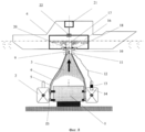
Надводное судно - 4 (Фиг.3) имеет осушаемый трюм - 16, в котором размещена вертикальная шахта - 17, нижний срез которой расположен под днищем судна - 4 и на котором размещено стыковочное устройство - 18 с конусной ловушкой - 19 и фланцем - 20 для плотного контакта с торцом комингса - 9 (см. также Фиг.1) сетчатой оболочки - 5 (см. также Фиг.1). Верхний срез шахты - 17 расположен ниже уровня акватории. Над шахтой - 17 размещен тросовый спускоподъемный механизм - 21 с автоматическим захватным устройством - 22, выполненным преимущественно в виде разжимной цанги для втягивания комингса - 9 (см. также Фиг.1) сетчатой оболочки - 5 (см. также Фиг.1) в конусную ловушку - 19 стыковочного устройства - 18.The surface vessel - 4 (Figure 3) has a drained hold - 16, in which a vertical shaft - 17 is located, the lower section of which is located under the bottom of the vessel - 4 and on which the docking device - 18 with a cone trap - 19 and a flange - 20 for close contact with the end face of coaming - 9 (see also Figure 1) of the mesh shell - 5 (see also Figure 1). The upper section of the mine - 17 is located below the level of the water area. Above the mine - 17 there is a cable hoisting mechanism - 21 with an automatic gripping device - 22, made mainly in the form of an expanding collet for drawing coaming - 9 (see also Figure 1) of the mesh shell - 5 (see also Figure 1) into a conical trap - 19 docking device - 18.
Комплекс (Фиг.4 и 5), преимущественно для транспортировки массивных подводных объектов содержит плоскую раму - 23 с рымами (не показаны) для крюков - 8 сетчатой оболочки - 5 и дистанционно управляемыми захватными устройствами - 24 на штоках регулируемой длины - 25, которые закреплены на раме - 23 с помощью шарниров - 26. Промежутки между штоками - 25 затянуты сетчатыми пластинами - 27, закрепленными одним краем на раме-23. Плоская рама - 23 имеет прочные конструктивные элементы (не показаны), совместимые с захватными устройствами - 15 самоходных подводных средств - 2, и кабель - 28 с подводной вилкой - 29 для подключения к управляемым разъемам - 14 самоходных подводных средств - 2.The complex (Figs. 4 and 5), mainly for transporting massive underwater objects, contains a flat frame - 23 with eyelets (not shown) for hooks - 8 mesh shell - 5 and remotely controlled gripping devices - 24 on rods of adjustable length - 25, which are fixed on the frame - 23 with the help of hinges - 26. The gaps between the rods - 25 are tightened by mesh plates - 27, fixed with one edge on the frame-23. The flat frame - 23 has strong structural elements (not shown) that are compatible with grippers - 15 self-propelled underwater vehicles - 2, and cable - 28 with an underwater plug - 29 for connecting to controlled connectors - 14 self-propelled underwater vehicles - 2.
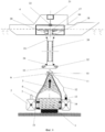
Комплекс (Фиг.6) для работы в акваториях, где глубина не позволяет непосредственно подтянуть комингс - 9 к стыковочному устройству - 18, дополнительно включает трубопровод - 30, один конец которого выполнен в виде жесткого цилиндра с фланцем - 31 для упора на фланец - 20 вертикальной шахты - 17 надводного судна - 4. На втором конце трубопровода - 30 установлено управляемое с борта надводного судна стыковочное устройство - 32 с конусной ловушкой - 33 и опорным фланцем - 34 для плотного контакта трубопровода - 30 с торцом комингса - 9 сетчатой оболочки - 5.The complex (Fig. 6) for operation in water areas where the depth does not allow directly pulling coaming - 9 to the docking device - 18, additionally includes a pipeline - 30, one end of which is made in the form of a rigid cylinder with a flange - 31 for emphasis on the flange - 20 vertical shaft - 17 surface vessel - 4. At the second end of the pipeline - 30, a docking device controlled by the side of the surface vessel - 32 with a cone trap - 33 and a support flange - 34 is installed for tight contact of the pipeline - 30 with the end face of the coaming - 9 mesh shell - 5 .
Реализация способа транспортировки негабаритного подводного объекта с помощью комплекса происходит следующим образом (Фиг.1-8).The implementation of the method of transporting an oversized underwater object using the complex is as follows (Fig.1-8).
Объект транспортировки 1 на береговой площадке подготавливают к транспортировке. Также производят подготовку сетчатой оболочки 5. Для этого, основываясь на предварительном расчете необходимого количества плавучих элементов. Затем с помощью механизма 11, который для этого через кабель 12 временно подключают к береговому источнику электроэнергии, регулируют и фиксируют длину внешних связей 6, таким образом, устанавливая предварительные размеры сетчатой оболочки 5.The
С помощью подъемного крана сетчатую оболочку 5 надевают на объект 1 и скрепляют ее с объектом с помощью крюков 8 захватных устройств 7 (см. Фиг.1).Using a crane, the
Объект 1 вместе с установленной на нем сетчатой оболочкой 5 устанавливают на площадку, расположенную на глубине, превышающей вертикальный размер сетчатой оболочки 5 (Фи.7). Погрузочная площадка может быть оборудована, например, в плавучем доке.
К месту установки транспортируемого объекта подводят самоходные подводные средства, погружают их рядом с объектом и с помощью управляемых захватных устройств 15 производят стыковку самоходных подводных средств 2 с объектом транспортировки 1. С помощью подводной вилки 13 подключают кабель 12 привода (не показан) заслонки 10 и механизма фиксации и натяжения 11 к управляемому разъему 14. При этом заслонка 10 комингса 9 сетчатой оболочки 5 закрыта.Self-propelled underwater means are brought to the installation site of the transported object, immersed next to the object and, using controlled
Далее с помощью гибких рукавов, по которым прокачивают воду из акватории, производят заполнение сетчатой оболочки плавучими телами 3. При этом выходные отверстия рукавов предварительно располагают в требуемом порядке и направляют в заранее определенные области пространства под сетчатой оболочкой 5. Ввод плавучих тел в рукава производят с использованием подходящих инжекционных устройств (в зависимости от глубины по маршруту транспортировки и на месте доставки объекта в качестве плавучих тел могут быть использованы шары из полистирола, твердого пенопласта, полимерные или металлические сферы).Then, with the help of flexible hoses, along which water is pumped from the water area, the mesh shell is filled with floating
По завершении заполнения сетчатой оболочки 5 необходимым количеством плавучих тел с помощью механизма 11 производят окончательную затяжку и фиксацию внешних натяжных связей 6 сетчатой оболочки 5.Upon completion of the filling of the
Далее, используя дополнительные цистерны уравнительных и дифферентных систем, которыми оснащены самоходные подводные средства 2, производят вывеску системы «объект - самоходные подводные средства» оставаясь в подводном положении. В процессе вывески, при необходимости, под оболочку 5 может быть введено дополнительное количество плавучих тел. После этого система «объект - самоходные подводные средства» переходит в надводное положение.Further, using additional tanks of leveling and trim systems, which are equipped with self-propelled underwater means 2, a sign is made of the system "object - self-propelled underwater means" while remaining in the underwater position. In the process of signage, if necessary, an additional number of floating bodies can be introduced under the
Затем систему «объект - самоходные подводные средства» выводят в исходную точку маршрута транспортировки по ледовому каналу, проделанному надводным судном 4. Далее система погружается на необходимую глубину и следует в сопровождении судна 4 к месту назначения транспортируемого объекта. При достаточной глубине на месте формирования система может начать движение по маршруту в подводном положении без помощи надводного судна.Then the system "object - self-propelled underwater means" is displayed at the starting point of the transportation route along the ice channel made by the
Достигнув места назначения с помощью самоходных подводных средств 2, система «объект - самоходные подводные средства» ложится на грунт или на площадку, приготовленную для установки подводного объекта, используя при этом те же приемы, что и при постановке подводных лодок на якорь в подводном положении.Having reached the destination with the help of self-propelled underwater means 2, the “object-self-propelled underwater means” system lays on the ground or on a site prepared for the installation of an underwater object, using the same techniques as when anchoring submarines in an underwater position.
Далее начинается процесс освобождения сетчатой оболочки от плавучих тел и механической связи с объектом транспортировки (Фиг.8).Next, the process of releasing the mesh shell from floating bodies and mechanical connection with the transport object begins (Fig. 8).
Надводное судно 4, принимает положение над объектом транспортировки 1. После этого с помощью спускоподъемного механизма 21 через шахту 17 осушаемого трюма 16 в комингс 9 сетчатой оболочки 5 опускают разжимное захватное устройство 22. По команде с подводных средств 2 передаваемой по кабелю 12 механизмы фиксации 11 освобождают гибкие внешние связи 6 сетчатой оболочки 5. После этого с помощью спускоподъемного механизма 21 подтягивают комингс 9 к стыковочному устройству 18 вплоть до стыковки комингса 9 с фланцем 20 шахты 17. По команде с борта самоходного подводного средства 2, передаваемой по кабелю 12 через разъем 13 открывают заслонку 10.The
Плавучие элементы 3 свободно всплывают на поверхность воды в трюм 16 надводного судна. При этом для облегчения и ускорения выхода плавучих элементов, заслонка 10 под действием своего привода (не показан) совершает малые колебания относительно среднего положения.Floating
После переход всех плавучих тел 3 в трюм 16 надводного судна 4 по кабелю 12 с подводного средства 2 подается команда на срабатывание захватных устройств 7 сетчатой оболочки 5 (см. также Фиг.1). Оболочка освобождается от механического контакта с объектом 1. Одновременно с помощью управляемого подводного разъема 14 отсоединяют вилку 13 кабеля 12 (см. также Фиг.2).After the transition of all the floating
После этого срабатывают захватные устройства 15 самоходных подводных средств 2. Происходит разъединение самоходных средств 2 и объекта транспортировки 1.After that, the
Затем сетчатую оболочку с помощью спускоподъемного механизма 21 и захватного устройства 22 приподнимают и принимают на борт судна 4.Then the mesh shell using the
Далее самоходные подводные средства 2 в сопровождении надводного судна 4 возвращаются в пункт базирования для подготовки к следующей транспортной операции.Next, the self-propelled underwater means 2, accompanied by a
В том случае, когда глубина моря в месте установки транспортируемого объекта не позволяет стыковать комингс 9 к фланцу 20 стыковочного устройства 18 надводного судна 4 процесс освобождения сетчатой оболочки от плавучих тел и механической связи с объектом транспортировки осуществляется следующим образом (Фиг.9).In the case when the depth of the sea at the installation site of the transported object does not allow the
С помощью спускоподъемного устройства 21 и захватного устройства 22 через шаху 17 к комингсу 9 сетчатой оболочки 5 опускают трубопровод 30.Using the
С помощью конусной ловушки 33 осуществляют стыковку торца комингса 9 с фланцем 34 и по команде с надводного судна 4 фиксируют их взаимное положение с помощью стыковочного устройства 32 (трубопровод 30 необходимой длины формируют предварительно на стадии подготовки транспортной операции, например, путем сборки его из коротких секций). Длина трубопровода должна несколько превышать расстояние между фланцем 20 и торцом комингса 9 сетчатой оболочки 5. Другие действия осуществляются также и в том же порядке как это описано выше.Using a
Если транспортируемый объект имеет подводный вес, для компенсации которого не хватает объема сетчатой оболочки в случае ее присоединения непосредственно к корпусу объекта, используют промежуточную раму 23 (Фиг.4 и 5).If the transported object has underwater weight, to compensate for which there is not enough volume of the mesh shell if it is attached directly to the body of the object, use an intermediate frame 23 (Figs. 4 and 5).
Подготовка комплекса к транспортной операции происходит следующим образом.Preparation of the complex for the transport operation is as follows.
На береговой площадке транспортируемый подводный объект 1 устанавливают внутри рамы 23.On the coastal platform, the transportable
С помощью захватный устройств 24 на штоках регулируемой длины 25 объект 1 скрепляют с рамой 23.Using
Затем сетчатую оболочку 5 с помощью крюков 8 захватных устройств 7 используя рымы (на рисунке не показаны) скрепляют с рамой 23. Затем собранную конфигурацию «объект - рама - сетчатая оболочка» устанавливают на погрузочной площадке. После этого с помощью захватных устройств 15 самоходные подводные средства 2 скрепляют с рамой 23 формируя, таким образом, систему «объект - рама - сетчатая оболочка - самоходные подводные средства».Then the
С помощью вилки 29 подключают кабель 28 к управляемому разъему 14 самоходного подводного средства 2. Производят заполнение сетчатой оболочки 5 необходимым количеством плавучих тел 3 и вывешивание в подводном положении сформированной системы «объект - рама - сетчатая оболочка - самоходные подводные средства». Дальнейшие действия производят также, как это описано выше.Using a
После завершения перехода к месту доставки объекта и покладки системы «объект - рама - сетчатая оболочка - самоходные подводные средства» на грунт сетчатую оболочку 5 освобождают от плавучих тел 3 также как это описано выше с применением или без применения трубопровода 30 (см. также Фиг.8 и 9).After completion of the transition to the place of delivery of the object and laying of the system "object - frame - mesh shell - self-propelled underwater means" on the ground, the
После этого срабатывают захватные устройства 15 и управляемый разъем 14 самоходных подводных средств 2. Самоходные подводные средства отделяются от рамы 23.After that, the
Раму вместе с сетчатой оболочкой принимают на борт надводного судна 4.The frame, together with the mesh shell, is taken aboard the
Далее самоходные подводные средства в сопровождении надводного судна возвращаются в пункт базирования для подготовки к следующей транспортной операции.Next, self-propelled underwater vehicles accompanied by a surface vessel are returned to the base point in preparation for the next transport operation.
Предлагаемый способ транспортировки негабаритного подводного объекта и комплекс для его реализации обеспечивают независимость процесса транспортировки подводных объектов от наличия и состояния ледового покрова акватории, минимизацию водоизмещения самоходных подводных транспортных средств, универсализацию комплекса транспортировки негабаритных подводных объектов по отношению к массе и габаритам транспортируемого подводного объекта, упрощение и удешевление эксплуатации комплекса, упрощение и удешевление модернизации комплекса, улучшение экологических параметров комплекса.The proposed method of transporting an oversized underwater object and a complex for its implementation ensure the independence of the transportation of underwater objects from the presence and condition of the ice cover of the water area, minimizing the displacement of self-propelled underwater vehicles, universalizing the transportation complex of oversized underwater objects with respect to the mass and dimensions of the transported underwater object, simplifying and cheaper operation of the complex, simplification and cheapening of modernization of the complex , improving the environmental parameters of the complex.
Claims (7)
Priority Applications (1)
| Application Number | Priority Date | Filing Date | Title |
|---|---|---|---|
| RU2011141142/11A RU2500569C2 (en) | 2011-10-11 | 2011-10-11 | Method of outsize underwater structures transfer and complex to this end |
Applications Claiming Priority (1)
| Application Number | Priority Date | Filing Date | Title |
|---|---|---|---|
| RU2011141142/11A RU2500569C2 (en) | 2011-10-11 | 2011-10-11 | Method of outsize underwater structures transfer and complex to this end |
Publications (2)
| Publication Number | Publication Date |
|---|---|
| RU2011141142A RU2011141142A (en) | 2013-04-20 |
| RU2500569C2 true RU2500569C2 (en) | 2013-12-10 |
Family
ID=49151847
Family Applications (1)
| Application Number | Title | Priority Date | Filing Date |
|---|---|---|---|
| RU2011141142/11A RU2500569C2 (en) | 2011-10-11 | 2011-10-11 | Method of outsize underwater structures transfer and complex to this end |
Country Status (1)
| Country | Link |
|---|---|
| RU (1) | RU2500569C2 (en) |
Citations (4)
| Publication number | Priority date | Publication date | Assignee | Title |
|---|---|---|---|---|
| FR489093A (en) * | 1915-06-05 | 1918-12-13 | Tedoldi Ettore Minari | New system for refloating sunken ships |
| US3286672A (en) * | 1964-06-01 | 1966-11-22 | Lehmann Guenther Wolfgang | Deep sea salvage equipment |
| RU2081026C1 (en) * | 1994-03-01 | 1997-06-10 | Александр Семенович Криворотов | Complex for raising sunken objects |
| RU2349490C2 (en) * | 2007-05-02 | 2009-03-20 | Федеральное государственное образовательное учреждение высшего профессионального образования Астраханский государственный технический университет (ФГОУ ВПО АГТУ) | Device for lifting sunken object |
-
2011
- 2011-10-11 RU RU2011141142/11A patent/RU2500569C2/en active
Patent Citations (4)
| Publication number | Priority date | Publication date | Assignee | Title |
|---|---|---|---|---|
| FR489093A (en) * | 1915-06-05 | 1918-12-13 | Tedoldi Ettore Minari | New system for refloating sunken ships |
| US3286672A (en) * | 1964-06-01 | 1966-11-22 | Lehmann Guenther Wolfgang | Deep sea salvage equipment |
| RU2081026C1 (en) * | 1994-03-01 | 1997-06-10 | Александр Семенович Криворотов | Complex for raising sunken objects |
| RU2349490C2 (en) * | 2007-05-02 | 2009-03-20 | Федеральное государственное образовательное учреждение высшего профессионального образования Астраханский государственный технический университет (ФГОУ ВПО АГТУ) | Device for lifting sunken object |
Also Published As
| Publication number | Publication date |
|---|---|
| RU2011141142A (en) | 2013-04-20 |
Similar Documents
| Publication | Publication Date | Title |
|---|---|---|
| CA2770346C (en) | Method and apparatus for subsea installations | |
| RU2719516C1 (en) | Bottom-based platform and method of creating drilling terminal for drilling in shallow-water shelf | |
| RU2719645C1 (en) | Mounting base resting on seabed and method for installation thereof | |
| US6113314A (en) | Disconnectable tension leg platform for offshore oil production facility | |
| EP3209548B1 (en) | Method for transporting a buoyant structure with a vessel, and the vessel associated with the method | |
| AU2009283041B2 (en) | Subsea structure installation or removal | |
| WO2018074977A1 (en) | System and method for reconfiguring a mobile docking apparatus for transporting, removal, installation, housing and transferring assets | |
| US8858149B2 (en) | Remote docking port | |
| EP2326552B1 (en) | Method of locating a subsea structure for deployment | |
| KR20210010997A (en) | Wind turbine and method for installing wind turbine | |
| CN106677258A (en) | Installing process of offshore water taking head caisson of power plant | |
| GB2378472A (en) | Method of constructing a floating offshore structure | |
| MX2010005554A (en) | Self-standing riser and buoyancy device deployment and positioning system. | |
| WO2010109243A2 (en) | Apparatus and method for handling a submersible item | |
| KR20150115977A (en) | Transport construction apparatus of lower structure of marine wind power and method thereof | |
| US3621662A (en) | Underwater storage structure and method of installation | |
| RU2500569C2 (en) | Method of outsize underwater structures transfer and complex to this end | |
| JP6890178B2 (en) | Port plants and methods for mooring floats in port plants | |
| TWI702327B (en) | Harbour plant and method for mooring a floating body in a harbour plant | |
| GB2538362A (en) | Frame for marine energy harvester | |
| CA2248578A1 (en) | Disconnectable tension leg platform for offshore oil production facility | |
| Sablok et al. | Disconnectable arctic spar | |
| AU2013101562A4 (en) | Buoy | |
| RU2245271C1 (en) | Technical fleet ship, underwater system for single-leg mooring and servicing of ships and method of erection of such system | |
| RU158156U1 (en) | MARINE TECHNOLOGICAL ICE-RESISTANT PLATFORM |
Legal Events
| Date | Code | Title | Description |
|---|---|---|---|
| PC41 | Official registration of the transfer of exclusive right |
Effective date: 20180712 |